DigitroniK Digital Indicating Controller SDC40A
DigitroniK Digital Indicating Controller SDC40A
DigitroniK Digital Indicating Controller SDC40A

You also want an ePaper? Increase the reach of your titles
YUMPU automatically turns print PDFs into web optimized ePapers that Google loves.
No. CP–SS–1580E<br />
<strong>DigitroniK</strong><br />
<strong>Digital</strong> <strong>Indicating</strong> <strong>Controller</strong><br />
<strong>SDC40A</strong><br />
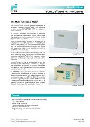
The <strong>DigitroniK</strong> <strong>SDC40A</strong> is a compact (96mm x 96mm) digital<br />
controller. The <strong>SDC40A</strong> features a wide variety of input<br />
options: thermocouples, resistance temperature detectors, DC<br />
voltage and DC current inputs are supported.<br />
Control outputs consist of time proportional PID (relay output,<br />
voltage output), current output PID, position proportional<br />
PID, and heat/cool PID. The <strong>SDC40A</strong> simplifies control with<br />
PID auto tuning and systems. The <strong>SDC40A</strong> can optionally<br />
be provided with a maximum of 12 remote switch inputs<br />
and a maximum of 8 event outputs for automatic operation<br />
in combination with a PLC.<br />
■ Features<br />
• Four or five digit display.<br />
• Accuracy of ±0.1% FS.<br />
• 100ms input sampling cycle.<br />
• Input type and range are selectable by operator keys.<br />
• Up to eight individual set points.<br />
• Eight groups of PID control constants. These can also be<br />
automatically set by autotuning.<br />
• Group of gain constants enables variable gain control.<br />
• Set point change rate can be set using the SP ramp function.<br />
• Two event outputs are standard.<br />
• The remote SP model features one group of ratio constants<br />
for ratio control.<br />
• Computer backup of process data is available in the remote<br />
SP model.<br />
• Internal cascade algorithm provides internal linking of the<br />
primary and secondary controllers in one device.<br />
• Two user-defined pushbuttons are available.<br />
• A 10-segment bargraph displays 0-100% control output at<br />
a glance. It can also be used as a “Green belt” OK indicator,<br />
event output monitor, remote switch input or motor<br />
opening monitor.<br />
• To enable use in a wide range of application options include:<br />
★ Events (3, 8 points) ★ <strong>Digital</strong> inputs (4, 12 points)<br />
★ Auxiliary output (1 or 2 points)<br />
★ Serial communications (RS-485, RS-232C)<br />
• Basic models:<br />
· Standard model · Remote SP model<br />
· Internal cascade model<br />
• CE approval obtained<br />
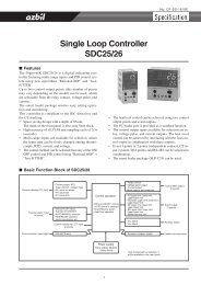
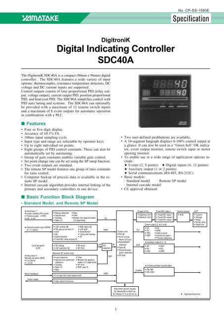
■ Basic Function Block Diagram<br />
• Standard Model, and Remote SP Model<br />
Analog Input 1<br />
Process variable (PV) inputs<br />
• Thermocouple • RTD<br />
• mA • mV<br />
★ Remote switch input (RSW)<br />
(4, 12 inputs)<br />
Local set point<br />
(LSP)<br />
Analog input 2<br />
Remote set point (RSP)<br />
• 4 to 20mA<br />
• 1 to 5V<br />
Motor feedback<br />
• Range selection • Bias<br />
• Square root • Filter<br />
• Scaling • Broken line approximation<br />
• Ratio (1) (12 segments)<br />
• LSP number (8) • RSP ration (8)<br />
• PID group number (7) • LSP shift<br />
• A/M<br />
• RUN/READY<br />
• R/L<br />
• Computer backup<br />
• Direct/reverse • AT<br />
• Fixed MV value output (3)<br />
• SP setting<br />
• LSP selection (8)<br />
(Remode SP model only)<br />
• SP ramp<br />
• SP limit<br />
• Input selection • Filter<br />
• Square root extraction • Broken line approximation<br />
(12 segments)<br />
operation<br />
• Scaling<br />
• SP limit<br />
• Ratio (1)<br />
• RSP ratio (7)<br />
• Bias<br />
• Full open/full close adjustment<br />
LSP<br />
PV<br />
RSW<br />
R/L<br />
selection<br />
MFB<br />
RSP<br />
SP<br />
Control unit<br />
• PID (8)<br />
• Auto tuning+<br />
Neuro & Fuzzy<br />
• RUN/READY<br />
selection<br />
• Gain (9)<br />
• Direct/reverse<br />
action selection<br />
• SP limit<br />
Output limits<br />
• High/low limit<br />
• Variation limit<br />
EV<br />
AUX<br />
COMM<br />
Fixed MV output<br />
• Fixed MV value 1<br />
• Fixed MV value 2<br />
• Fixed MV value 3<br />
Event output (2, ★ 3 to 8)<br />
• SP • MV<br />
• PV • MFB<br />
• DEV • Status event<br />
• RSP • Instrument alarm<br />
• Process diagnosis<br />
★ Auxiliary outputs (1, 2)<br />
• SP<br />
• PV<br />
• DEV<br />
• RSP<br />
• MV<br />
• MFB<br />
★ Communication input/output<br />
• RS-485<br />
• RS-232C<br />
Control output<br />
• A/M<br />
OUT<br />
• Current<br />
• Voltage<br />
• Relay<br />
• Motor drive<br />
• Heat/cool<br />
Smart loader<br />
• Data transmit/receive<br />
Instrument power supply<br />
AC Model 90 to 264V ac<br />
DC Model 21.6 to 26.4V dc<br />
★ : Optional functions<br />
1
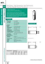
• Internal Cascade Model<br />
Analog input 2<br />
Process variable<br />
input (2) (PV2)<br />
• 4 to 20mA<br />
• 1 to 5V<br />
★ Remote switch (RSW)<br />
inputs, (4 or 12)<br />
Motor feedback<br />
Slave setting<br />
(S-LSP)<br />
Analog input 1<br />
Process variable<br />
input 1 (PV1)<br />
• Thermocouple • RTD<br />
• DC current • DC voltage<br />
• Range selection • Broken line<br />
• Square root approximation<br />
• Scaling<br />
(12 segments)<br />
• Ratio (1) • PV1PV2<br />
• Bias<br />
exchange<br />
• Filter<br />
• LSP number • Fixed MV<br />
• PID group number value output<br />
• A/M<br />
• LSP shift<br />
• R/L<br />
• RUN/READY<br />
• Direct/reverse • AT<br />
• LSP setting • SP limit<br />
• LSP selection (2)<br />
• Full open/full close adjustment<br />
• Input system • Filter<br />
selection • Broken line<br />
• Square root approximation<br />
• Scaling<br />
(12 segments)<br />
• Ratio (1) • PV1PV2<br />
• Bias<br />
exchange<br />
S-LSP<br />
MFB<br />
R/L<br />
selection<br />
RSP<br />
PV2<br />
PV1<br />
SP2<br />
• RSP scaling<br />
• RSP ratio (7)<br />
• SP limit<br />
• Variation limit<br />
Slave control unit<br />
• PID<br />
• Auto tuning<br />
• RUN/READY<br />
MV1<br />
Main control unit<br />
• PID<br />
• Gain (9)<br />
• Auto tuning +<br />
Neural & Fuzzy<br />
• Direct/reverse<br />
selection<br />
• RUN/READY<br />
Output limit<br />
• High/low<br />
limit<br />
EV<br />
AUX<br />
COMM<br />
Fixed mV output<br />
• Fixed mV value 1<br />
• Fixed mV value 2<br />
• Fixed mV value 3<br />
Event output (2, *3 to 8)<br />
• SP1, 2 • MV1, 2<br />
• PV1, 2 • MFB<br />
• DEV1, 2 • Each status event<br />
• RSP • Instrument alarm<br />
• Process diagnosis<br />
★ Auxiliary output (1, 2)<br />
• SP1, 2 • MV1, 2<br />
• PV1, 2 • DEV1, 2<br />
• S-LSP • RSP<br />
• MFB<br />
★ Communications<br />
• RS-485<br />
• RS-232C<br />
Control<br />
output<br />
• A/M<br />
OUT<br />
• Current<br />
• Voltage<br />
• Relay<br />
• Motor drive<br />
• Heat/cool<br />
MV2<br />
Main setpoint<br />
(M-LSP)<br />
Smart loader<br />
• LSP setting • LSP ramp<br />
• LSP selection (6)<br />
• Data transmit/receive<br />
SP1<br />
Instrument power supply<br />
AC Model 90 to 264V ac<br />
DC Model 21.6 to 26.4V dc<br />
★ : Optional functions<br />
■ Specifications<br />
Analog Type of inputs A variety of thermocouples, RTDs, mV and mA.<br />
input 1 Input display ±0.1% FS±1U (under standard conditions)<br />
(PV1 input) accuracy This may be affected by indication value conversion.<br />
Input sampling cycle<br />
100ms<br />
Input digital filter Variable 0.0 to 120.0s (there is no filter at 0.0)<br />
Input bias<br />
–1000 to +1000U (U: °C, KPa, % and other standard industrial units)<br />
Input ratio 0.001 to 9.999<br />
Input broken line 12 point broken line approximation can be assigned to analog inputs 1 or 2.<br />
approximation<br />
Square root opera- 0.0 to 10.0% FS (no square root calculation is performed at 0.0)<br />
tion dropout<br />
Input bias current Thermocouple, DC voltage input: ±1.3µA max. (peak, standard conditions)<br />
–3µA max. in the linear V range above 1V<br />
Input impedance<br />
DC current input: 50Ω ± 10% (under operating conditions)<br />
Measuring current RTD input: 1.04 mA ± 0.02 mA, terminal A (under operating conditions)<br />
Influence of Thermocouple: Variation in the displayed value due to input conversion when the wiring resistance at both<br />
wiring resistance ends is 250Ω:<br />
• M01, L02; 35µV max. • L01; 60µV max. • Others; 750µV max.<br />
RTD: ±0.01% FS/Ω max. within wiring resistance range of 0 to 10Ω.<br />
±0.02% FS/Ω in the range whose minimum resolution is 0.01°C.<br />
The allowable wiring resistance is 85Ω max. (except for 0.01°C resolution)<br />
(A zener barrier is available for on site adjustment.)<br />
Allowable parallel Allowable parallel resistance for thermocouple break detection is 1MΩ min.<br />
resistance<br />
Maximum allowable Thermocouple, mV input: –5 to +15V<br />
input<br />
mA input: 28 mA<br />
Burnout<br />
Thermocouple input: Upscale + Alarm indication (AL01) (including the DC mV range)<br />
DC voltage input: Downscale + Alarm indication (AL02)<br />
DC current input: Downscale + Alarm indication (AL02)<br />
However, near 0% FS in the 0 to 20 mA range, neither burnout nor alarm<br />
indication is performed.<br />
RTD input: When “C” wire is broken: Upscale + Alarm indication (AL01 + AL09)<br />
When resistance element and “A” wire, or resistance element and “B” wire, or “A”<br />
wire and “B” wire are broken: Upscale + Alarm indication (AL01 + AL07)<br />
When “B” wire, or resistance element and “C” wire, “A” wire and “C” wire, or “B”<br />
wire and “C” wire, or resistance element, “B” wire and “C” wire, or “A” wire, “B” wire<br />
and “C” wire are broken: Upscale + Alarm indication (AL01 + AL08)<br />
Over range detec- Higher than 110% FS: Upscale<br />
tion threshold Lower than –10% FS: Downscale (however, downscaling is not performed by F50 and P50<br />
models. The lower indication limit of the B19 model is 20°C/60°F.)<br />
Cold junction com- ±0.5°C (standard conditions)<br />
pensation accuracy<br />
Cold junction com- Compensation inside the instrument or compensation outside the instrument (0°C only) is selectable.<br />
pensation method<br />
2
Analog Type of input 4 to 20mA or 1 to 5V dc<br />
input 2 Input indication ±0.1% FS±1U (standard conditions), when converted to displayed value (may differ, depending on range)<br />
(RSP input accuracy<br />
of remote Input sampling cycle 0.1s<br />
SP model or<br />
PV2 input<br />
Input digital filter Variable 0.0 to 120.0s (there is no filter at 0.0)<br />
of internal Input bias –19999 to +30000U<br />
cascade Input ratio<br />
0.001 to 30,000 (gain cannot be used in case of selection of the multi ratio of 8 groups. Trade off.)<br />
model)<br />
Input broken line 12 broken lines of approximation<br />
approximation (which can be assigned to either of analog inputs 1 or 2.)<br />
Square root oper- 0.0 to 10.0% FS (no square root calculation is performed at 0.0.)<br />
ation threshold<br />
Scaling<br />
Input bias current<br />
Input impedance<br />
–19999 to +26000U (reverse scaling is also possible. The decimal point position can be changed. Resolution<br />
is 1/26000.)<br />
1 to 5V input: +10µA max. (under operating conditions)<br />
1 to 5V input: 1MΩ min. (under operating conditions)<br />
4 to 20mA input: 50Ω ±10% (under operating conditions)<br />
Allowable maximum 1 to 5V input: 0 to 6V<br />
input<br />
4 to 20mA input: 28mA<br />
Burnout<br />
Over range detec-<br />
tion threshold<br />
PV1 ↔ PV2 switch<br />
Downscale + Alarm indication (AL04)<br />
More than 110% FS: Regarded as upscale.<br />
Indications PV and SP indication 5-digit 7-segment LED<br />
and setting Function indication 2-digit 7-segment LED<br />
LED bar<br />
Status indication<br />
Operating keypad<br />
Less than –10% FS: Regarded as downscale.<br />
Internally switchable in the internal cascade model.<br />
Ten LED segments out of twelve indicate control output:<br />
• When motor opening indication (2G) is selected, ten segments are used.<br />
• When the OK indicator function is selected, all twelve segments are used as a ”green belt”.<br />
• This LED bar can also be used to monitor events 4 to 8 and RSW 1 to 12.<br />
18 LEDs (some models do not include all indicators)<br />
13 rubber keys (there may be dead keys depending on model).<br />
Number of set points 1 to 8 points (selection and changeover use available) with the internal cascade model, up to 6<br />
points are allowed on the master side, up to 2 points are allowed on the slave side.<br />
Memory storage<br />
Indication ranges<br />
Setting range<br />
Indication masking<br />
SP limits<br />
Non-volatile semiconductor memory (EEPROM)<br />
–10 to +110% FS of range or scaling value (–10% FS is not applicable for F50, P50 and B18<br />
models.)<br />
–19999 to +26000U (when an SP limit is applied, the relevant value is used.)<br />
The least significant digit can be masked for 4-digit indication.<br />
Low limit: –19999U to high limit value<br />
High limit: Low limit value to 26000U<br />
SP ramp (separately UP ramp: 0 to 26000U (no ramp at 0) Down ramp: 0 to 26000U (no ramp at 0)<br />
set for LSP and RSP) The measurement interval can be selected from among the following:<br />
• U/hr • 0.1U/hr • U/min • 0.1U/min<br />
Control Model number 0D 2G 5G 6D 3D, AK, 5K, 9K, BK<br />
output Type of output SPDT relay contact M/M driving relay Current output Voltage output (load *See Table 1.<br />
output contact output (4 to 20mA dc) current is adjustable)<br />
Control action Time proportional PID Position proportional Current proportional Time proportional 2-stage (heat/cool)<br />
PID PID PID PID<br />
No. of PID groups 8 groups 8 groups 8 groups 8 groups 4groups on each of<br />
heat and cool sides<br />
PID autotuning Autotuning allowed. Autotuning allowed. Autotuning allowed. Autotuning allowed. Autotuning not allowed.<br />
Output rating<br />
Contact rating:<br />
Contact ratings:<br />
Max, allowable load Max. allowable load Table 1<br />
5A<br />
2.5A (30V dc L/R=0.7ms) resistance:<br />
internal resistance:<br />
Heat side Cool side<br />
(30V dc/ 120V ac,<br />
4A (120V ac COS φ = 0.4) 680Ω (under operating 680Ω (under operating<br />
3D 0D 0D<br />
resistive load)<br />
2A (240V ac COS φ = 0.4) conditions)<br />
conditions)<br />
4A<br />
Allowable contact voltage: Output accuracy:<br />
Load current setting AK 0D 5G<br />
(240V dc, resistive load) 250V ac, resistive load ±0.1% FS max.<br />
accuracy:<br />
5K 5G 5G<br />
±0.2% FS max. (under<br />
Allowable contact voltage: 125V dc, resistive load (under operating<br />
operating conditions)<br />
9K 0D 6D<br />
250V ac, resistive load 125V dc L/R=0.7ms conditions)<br />
Load current setting BK 5G 6D<br />
125V dc, resistive load 250V ac COS φ = 0.4 Output resolution:<br />
resolution: 1/200min<br />
Maximum switching power: Maximum switching power: 1/2000 min<br />
Inrush current:<br />
In the heat/cool model, the<br />
150W, 960VA (resistive 75W (L/R=0.7ms) Inrush current:<br />
25mA max. 50ms max. output type differs between<br />
load)<br />
480VA (COS φ = 0.4) 25mA max., 50ms max. (with 250Ω load)<br />
the heat side and cool side<br />
Mechanical life:<br />
Mechanical life:<br />
(with 250Ω load)<br />
Maximum output current:<br />
as shown in the above table.<br />
10,000,000 repetitions 10,000,000 repetitions Maximum output current: 21.6mA dc<br />
Each output rating is the<br />
Electrical life:<br />
Electrical life:<br />
21.6mA dc<br />
Minimum output current:<br />
same as for 0D, 2G, 5G, or<br />
100,000 repetitions (at 100,000 repetitions Minimum output current: 2.4mA dc<br />
6D.<br />
contact rating, COS φ =1, (at contact rating,<br />
2.4mA dc<br />
Off time leak current:<br />
frequency 30 times/min) COS φ = 0.4, frequency Opening terminal voltage: 100 µA max. (with load is<br />
• The heat side and cool side<br />
Minimum switching<br />
30 times/min)<br />
25V max.<br />
shorted under operating<br />
ca be switched.<br />
voltage: 5V<br />
Minimum switching Output update cycle:<br />
conditions)<br />
Output update cycle: • Direct or reverse action can<br />
Minimum switching current: voltage: 5V<br />
100ms<br />
100ms<br />
be selected by remote<br />
100mA<br />
Minimum switching<br />
Minimum on-off time: switching, as in the other<br />
Minimum on/off time: current: 100mA<br />
100ms on, on-off control models.<br />
100ms on, on/off control<br />
100ms on, time<br />
100ms on, time<br />
proportional control<br />
proportional control<br />
(cycle time: 10s min.)<br />
0.1% of cycle time (cycle<br />
time: less than 10s)<br />
Proportional band 0.0 to 1000.0% FS 0.1 to 1000.0% FS 0.1 to 1000.0% FS 0.0 to 1000.0% FS 0.1 to 1000.0% FS<br />
(P) (On-off operation (On-off operation is (On-off operation is (On-off operation (On-off operation is<br />
when P=0) not allowed) not possible) when P=0) not allowed)<br />
3
Control Model number 0D 2G 5G 6D 3D, AK, 5K, 9K, BK<br />
output Cycle time 5 to 120s 1 to 60s Same as for each<br />
(setting possible — — (setting possible type of output<br />
every second)<br />
every second)<br />
Integral time (I) 0 to 3600s 0 to 3600s 0 to 3600s 0 to 3600s 0 to 3600s<br />
(PD action when I=0) (PD action when I=0) (PD action when I=0) (PD action when I=0) (PD action when I=0)<br />
Derivative time (D) 0 to 1200s 0 to 1200s 0 to 1200s 0 to 1200s 0 to 1200s<br />
(PI action when D=0) (PI action when D=0) (PI action when D=0) (PI action when D=0) (PI action when D=0)<br />
Differential gap 0 to 1000U<br />
—<br />
0 to 1000U 0 to 1000U Same as in each<br />
(in on-off operation) (in on-off operation) (in on-off operation) output type.<br />
Dead band — 0.5 to 25.0% OUT — — –100.0 to +5.0% OUT<br />
Output limiter Low limit value:<br />
–10% to high limit value<br />
(–10 to 0% become 0%)<br />
High limit value:<br />
Low limit value:<br />
–10% to high limit value<br />
High limit value:<br />
Low limit value to 110%<br />
Low limit value:<br />
–10% to high limit value<br />
High limit value:<br />
Low limit value to 110%<br />
Low limit value:<br />
–10% to high limit value<br />
(–10 to 0% become 0%)<br />
High limit value:<br />
Low limit value:<br />
–10% to high limit value<br />
High limit value:<br />
Low limit value to 110%<br />
Low limit value to 110%<br />
(100 to 110% become<br />
100%)<br />
Low limit value to 110%<br />
(100 to 110% become<br />
100%)<br />
Manipulated variable 1 to 100% 1 to 100% 1 to 100% 1 to 100% 1 to 100%<br />
change rate limiter (every 100 ms) (every 100 ms) (every 100 ms) (every 100 ms) (every 100 ms)<br />
MFB (Motor Feed<br />
—<br />
100 to 2500Ω<br />
back) input range<br />
— — —<br />
MFB (Motor Feed<br />
Whether action is to be<br />
back) break control — continued is selected by — — —<br />
MFB position assumption.<br />
Variable gain If the load characteristic of the control system is non-linear, stable control characteristics are obtained by<br />
changing the gain according to the deviation. Control conforms to the following equation:<br />
1<br />
Set proportional band (p) X<br />
= Real proportional band.<br />
Gain value<br />
Set value range: 0.01 to 300.00<br />
Gain 1: when –20% FS Gain 6: when 2% FS<br />
Gain 2: when –10% FS Gain 7: when 5% FS<br />
Gain 3: when –5% FS Gain 8: when 10% FS<br />
Gain 4: when –2% FS Gain 9: when 20% FS<br />
Gain 5: when 0% FS<br />
The gain ramp is automatically calculated using set gains, when the deviation is less than –20% or more than<br />
20%, calculation uses the extended characteristic.<br />
Remote No. of input points 4 or 12 (option)<br />
switch Connectable outputs Dry contact (relay contact) and open collector (current sink to ground)<br />
Input (RSW)<br />
Opening terminal +0.6V<br />
12V –1.6V between common terminal (No. 25) and each input terminal (under operating conditions)<br />
voltage<br />
Shorting terminal The current from each terminal is 5.0 to 6.6mA (under operating conditions)<br />
current<br />
Allowable contact resistance<br />
(dry contact)<br />
Residual voltage at<br />
open collector on time<br />
On: Less than 700Ω (under operating conditions)<br />
Off: More than 10kΩ (under operating conditions)<br />
3V max. (under operating conditions)<br />
Leak current at open 100µA max. (under operating conditions)<br />
collector off time<br />
Parallel connection Interconnection of <strong>SDC40A</strong> units is possible. Connection with compatible units other than <strong>SDC40A</strong> is also<br />
with other instrument allowed.<br />
Input sampling cycle 0.1s<br />
Minimum hold time 0.2s<br />
of on detection<br />
Function allocation NOP, RUN/READY, AUTO/MANUAL, REMOTE/LOCAL, AT start/stop, direct/reverse action, LSP number and<br />
PID number selection 0/+1, 0/+2, and 0/+4 (PID No. 0 cannot be selected)<br />
Fixed MV value output 1, 2 and 3<br />
LSP shift 0/+1, 0/+2, 0/+4, 0/+8, 0/+16, 0/+32, 0/+64, 0/+128, 0/+256, 0/+512<br />
Analog input 2 ratio number selection 0/+1, 0/+2, 0/+4<br />
Computer backup system 1 and 2<br />
LSP number<br />
selection<br />
(binary input)<br />
LSP shift<br />
(binary input)<br />
LSP<br />
shift width<br />
How to use LSP number / LSP shift<br />
RSW<br />
<strong>SDC40A</strong><br />
Set by configuration<br />
C55<br />
(–10000 to +10000U)<br />
50<br />
Set value by<br />
LSP number<br />
selection<br />
LSP 0 to 7<br />
Set value<br />
by LSP shift<br />
50 + 3 x 2<br />
56<br />
Set value<br />
LSP<br />
shift width<br />
Computer backup system usage<br />
OFF<br />
Normal operations<br />
Sensor<br />
PV<br />
Control<br />
output (mV)<br />
<strong>SDC40A</strong><br />
Sensor<br />
PID<br />
PV<br />
Remote<br />
switch<br />
The control output is used directly.<br />
On computer error<br />
ON<br />
Error<br />
Sensor<br />
PV<br />
Control<br />
output (mV)<br />
<strong>SDC40A</strong><br />
Sensor<br />
The output is changed over by remote switch input to control by <strong>SDC40A</strong><br />
One of the following two configurations must then be selected by the remote switch:<br />
1 PV at changeover is used as SP.<br />
2 LSP preset is used as SP.<br />
PID<br />
PV<br />
4
Event No. of output 2 points: standard (SPST relay contact).<br />
points<br />
1 point (SPDT relay contact) and 5 points (open collector output) can optionally be added.<br />
Event setting Direct PV Reverse PV Direct deviation Reverse deviation Direct absolute<br />
deviation value<br />
EV<br />
ON<br />
OFF<br />
PV<br />
Differential<br />
gap<br />
EV<br />
ON<br />
OFF<br />
PV<br />
Differential<br />
gap<br />
Reverse absolute Direct MV Reverse MV Direct RSP Reverse RSP<br />
deviation value<br />
SP+EV<br />
ON<br />
OFF<br />
PV<br />
Differential<br />
gap<br />
SP+EV<br />
ON<br />
OFF<br />
PV<br />
Differential<br />
gap<br />
EV<br />
Differential<br />
gap<br />
SP<br />
EV<br />
ON<br />
OFF<br />
PV<br />
Differential<br />
gap<br />
<br />
<br />
<br />
<br />
<br />
<br />
<br />
<br />
<br />
<br />
<br />
<br />
<br />
<br />
<br />
<br />
Differential<br />
gap<br />
<br />
<br />
Differential<br />
gap<br />
<br />
Differential<br />
gap<br />
Differential<br />
gap<br />
<br />
Differential<br />
gap<br />
Direct SP Reverse SP Direct motor Reverse motor All alarm sum<br />
feedback<br />
feedback<br />
<br />
<br />
<br />
<br />
EV<br />
<br />
ON<br />
EV<br />
ON<br />
<br />
Differential<br />
gap<br />
ON<br />
<br />
<br />
Differential<br />
gap<br />
<br />
<br />
Differential<br />
gap<br />
OFF<br />
MFB<br />
Differential<br />
gap<br />
OFF<br />
MFB<br />
Differential<br />
gap<br />
PV range alarm<br />
Instrument alarm<br />
OFF<br />
PV range alarm Instrument alarm Manual status READY status Local status<br />
ON<br />
ON<br />
ON<br />
ON<br />
ON<br />
OFF<br />
OFF<br />
OFF<br />
OFF<br />
OFF<br />
During PV over range<br />
—10% FS max.<br />
+110% FS min<br />
During instrument AL indication<br />
Manual status<br />
READY status<br />
Local status<br />
Auto tuning status<br />
ON<br />
OFF<br />
During AT<br />
Process diagnosis*<br />
ON<br />
OFF<br />
ON delay time<br />
* Process diagnosis event:<br />
This is turned ON if the event on delay time is exceeded, but the<br />
temperature does not rise beyond the differential gap (does not<br />
lower in the case of direct action) when the manipulated variable<br />
is larger than the event set output value.<br />
Setting range PV (direct, reverse): –19999 to +26000U RSP (direct, reverse): –19999 to +26000U<br />
Deviation (direct, reverse): –19999 to +26000U MFB (direct, reverse): –10.0 to +110.0%<br />
Absolute deviation value: 0 to 26000U Process diagnostics: –10.0 to +110.0%<br />
MV (direct, reverse): –10.0 to +110.0%<br />
Differential gap MV event, other than MFB: 0 to 200U,<br />
(hysteresis) setting MV event, MFB: 0.0 to 20.0%<br />
range<br />
However, when alarm event or status alarm is set, no differential gap can be set.<br />
On delay time<br />
Output action<br />
Output rating<br />
0 to 20000s(min) The on delay time can be set for event output EV1 to EV3.<br />
On-off<br />
Item<br />
Event<br />
EV 1 , EV 2 (standard) EV 3 (option) EV 4 to EV 8 (option)<br />
Type of output SPST (1a) relay contact SPDT (1a1b) relay contact Open collector output<br />
Contact rating 1A (30V dc/250V ac with 2A (30V dc/250V ac with<br />
resistive load)<br />
resistive load)<br />
—<br />
Allowable contact voltage 250V ac with resistive load 250V ac with resistive load<br />
30V dc with resistive load 30V dc with resistive load<br />
—<br />
Mechanical life 20,000,000 cycles 50,000,000 cycles —<br />
Electrical life 100,000 cycles (at contact 100,000 cycles (at contact<br />
rating, and frequency of 20 rating, and frequency of —<br />
times/min.), COSφ =1 20 times/min.), COSφ =1<br />
Minimum on-off voltage 10V 10V —<br />
Minimum on-off current 10mA (Use a bleeder 10mA (Use a bleeder<br />
resistor if necessary.) resistor if necessary.)<br />
—<br />
Load drive power voltage<br />
— —<br />
10 to 29V dc<br />
range<br />
Maximum output current<br />
— —<br />
70mA/point max. (under<br />
operating conditions)<br />
Off time leak current<br />
0.1mA/point max. (under<br />
— —<br />
operating conditions,<br />
within load drive power<br />
voltage range)<br />
Off time residual voltage<br />
1.6V max. (under operating<br />
conditions, within<br />
— — load drive power voltage<br />
range, and at maximum<br />
output current)<br />
5
Auxiliary No. of output points 1 or 2 (1 point in 2G, 3D, AK, 5K, 9K, and BK models)<br />
output Type of output Selectable from PV, SP, DEV, RSP, MV and MFB.<br />
Output rating<br />
Output accuracy<br />
Output resolution<br />
Inrush current<br />
Maximum output<br />
current<br />
Minimum output<br />
current<br />
Opening terminal<br />
voltage<br />
4 to 20mA dc. Max. allowable load resistance: 680Ω<br />
±0.1%FS (under standard conditions)<br />
1/10000 (numeric value of independent resolution; for example, the input resolution of PV or MFB is not included)<br />
25mA max. 50ms max. (with 250Ω load)<br />
21.6mA<br />
2.4mA<br />
Output update cycle 0.1s<br />
25V max.<br />
Communica- Communication Communication protocols RS-485 (Note 1) RS-232C<br />
tion system Network Multidrop<br />
The device is provided only with the<br />
slave station function, 1 to 16 units max.<br />
(DIM), 1 to 31 units max. (CMA, SCM).<br />
The device is provided only with the<br />
slave station function<br />
Data flow Half duplex Half duplex<br />
Synchronization Start/stop synchronization Start/stop synchronization<br />
Interface system Transmission system Balanced (differential) Unbalanced<br />
Data line Bit serial Bit serial<br />
Signal lines 5 transmit/receive lines (3-wire connec- 3 transmit/receive lines<br />
tion is also possible)<br />
Transmission speed 4800, 9600 bps 4800, 9600 bps<br />
Communication distance 500m max. (total) 15m max.<br />
Protocol RS-485 RS-232C<br />
Message characters Character configuration 11 bits/character 11 bits/character<br />
Format 1 start bit, even parity, and 1 stop bit, 1 start bit, even parity, and 1 stop bit,<br />
or 1 start bit, no parity, and 2 stop bits or 1 start bit, no parity, and 2 stop bits<br />
Data length 8 bits 8 bits<br />
Isolation<br />
Completely isolated between the input and output.<br />
Note 1. For RS-485, communications, the device can be connected not only to computers equipped with RS-485, but also to Yamatake<br />
Corporation's MX200, MA500 (DK link II DIM) or CMC10 controllers.<br />
General Memory backup Non-volatile semiconductor memory (EEPROM)<br />
specifica- Rated power voltage AC model: 90 to 264V ac 50/60Hz, DC model: 21.6 to 26.4V dc<br />
tions Power consumption AC model: 30VA max., DC model: 12W max.<br />
Power switching 15A max. 10ms (under operating conditions)<br />
inrush current Caution: When applying power to a number of <strong>SDC40A</strong>s simultaneously, ensure sufficient power is supplied, or<br />
start up the <strong>SDC40A</strong>s in series. Otherwise, the controllers may not start up normally due to voltage drop<br />
from the inrush current. It is necessary to reach the stable voltage within 2s of power being supplied.<br />
Insulation<br />
More than 20MΩ between power terminal 1 or 2 and ground terminal 3 (using 500V dc megger).<br />
resistance<br />
Dielectric strength 1500V ac (AC model) or 500V ac (DC model), 50/60Hz for 1 min between power terminal and ground terminal<br />
1500V ac, 50/60Hz for 1 min between relay output and ground terminal<br />
500V ac, 50/60Hz for 1 min between any other part and ground terminal<br />
500V ac, 50/60Hz for 1 min between isolated terminals<br />
Standard conditions Ambient temperature 23 ±2°C<br />
Ambient humidity<br />
60 ±5% RH<br />
Rated power voltage AC Model 105V ac ±1%<br />
Power frequency<br />
Vibration resistance 0m/s 2<br />
Shock resistance 0m/s 2<br />
DC Model 24V dc ±5%<br />
AC model: 50 ±1Hz or 60 ±1Hz<br />
Mounting angle Reference plane (vertical) ±3°<br />
Operating Ambient temperature range 0 to 50°C<br />
conditions Ambient humidity range 10 to 90% RH (non-condensing)<br />
Rated power voltage AC Model 90 to 264V ac<br />
Power frequency<br />
DC Model<br />
50 ±2Hz or 60 ±2Hz<br />
Vibration resistance 0 to 1.96m/s 2<br />
Shock resistance 0 to 9.81m/s 2<br />
21.6 to 26.4V dc<br />
Mounting angle Reference plane (vertical) ±10°<br />
Transport/storage Ambient temperature range –20 to +70°C<br />
conditions Ambient humidity range 10 to 95% RH (non-condensing)<br />
Materials of mask<br />
and case<br />
Vibration resistance<br />
Shock resistance<br />
Package drop test<br />
Mask: Multilon<br />
Case: Polycarbonate<br />
0 to 4.90m/s 2 (10 to 60Hz, for 2hr each in X, Y and Z directions)<br />
0 to 490m/s 2 (3 times in vertical direction)<br />
Drop height: 90cm (1 angle, 3 edges, 6 planes, freefall)<br />
6
General Colors of mask Mask: Dark gray<br />
specifica- and case Case: Light gray<br />
tions<br />
Mounting<br />
Panel flush type, using the dedicated mounting bracket<br />
Weight Approx. 750g (Extension terminal base: Approx. 150g)<br />
Standard Name Model No. Q'ty Name Model No.<br />
accessories<br />
Unit indicating label N-3132 1 Options Hard dust-proof cover set 81446083-001<br />
Mounting bracket 81405411-001 2 Soft dust-proof cover set 81446087-001<br />
Instruction manual CP-UM-1580E 1 Terminal cover 81446084-001<br />
PC loader<br />
SLP-C40AJ20<br />
Table of Selectable Inputs and Ranges<br />
Symbol °C Range °F Range<br />
K (CA) 0.0 to 1200.0 0 to 2400<br />
K (CA) 0.0 to 800.0 0 to 1600<br />
K (CA) 0.0 to 400.0 0 to 750<br />
K (CA) –200.0 to +1200.0 –300 to +2400<br />
K (CA) –200.0 to +300.0 –300 to +700<br />
K (CA) –200.0 to +200.0 –300 to +400<br />
E (CRC) 0.0 to 800.0 0 to 1800<br />
J (IC) 0.0 to 800.0 0 to 1600<br />
T (CC) –200.0 to +300.0 –300 to +700<br />
B (PR30-6) 0.0 to 1800.0 0 to 3300<br />
R (PR13) 0.0 to 1600.0 0 to 3100<br />
S (PR10) 0.0 to 1600.0 0 to 3100<br />
W (WRe5-26) 0.0 to 2300.0 0 to 4200<br />
W (WRe5-26) 0.0 to 1400.0 0 to 2552<br />
PR40-20 0.0 to 1900.0 0 to 3400<br />
Ni-Ni · Mo 0.0 to 1300.0 32 to 2372<br />
N 0.0 to 1300.0 32 to 2372<br />
PL II 0.0 to 1300.0 32 to 2372<br />
DIN U –200.0 to +400.0 –300 to +750<br />
DIN L –200.0 to +800.0 –300 to +1600<br />
Gold iron-chromel 0.0 to 300.0K —<br />
The ±0.1% FS input indication accuracy is not applicable to the following<br />
input conditions:<br />
Lower than –100°C on K thermocouple and T thermocouple: ±1°C ±1U<br />
Lower than 260°C on B thermocouple: ±4.0% FS ±1U<br />
260°C to 800°C of B thermocouple: ±0.4% FS ±1U<br />
800°C to 1800°C of B thermocouple: ±0.2% FS ±1U<br />
Lower than 100°C on R thermocouple and S thermocouple: ±0.2% FS ±1U<br />
100 to 1600°C on R thermocouple and S thermocouple: ±0.15%<br />
FS ±1U<br />
Lower than 300°C on PR40-20 thermocouple: ±2.5% FS ±1U<br />
300 to 800°C on PR40-20 thermocouple: ±1.5% FS ±1U<br />
800 to 1900°C on PR40-20 thermocouple: ±0.5% FS ±1U<br />
Gold iron-chromel: ±1.5K ±1U<br />
The range of two decimal digits of RTD input: ±0.15%FS ±1U<br />
0 to 10mV range: ±0.15%FS ±1U<br />
Lower than –100°C on DIN U: ±2°C ±1U<br />
Between –100°C and 0°C on DIN U: ±1°C ±1U<br />
Lower than –100°C on DIN L: ±1.5°C ±1U<br />
Symbol °C Range °F Range<br />
–200.0 to +500.0 –300.0 to +900.0<br />
–200.0 to +200.0 –300.0 to +400.0<br />
–100.0 to +150.0 –150.0 to +300.0<br />
JIS '89 Pt100 –50.0 to +200.0 –50.0 to +400.0<br />
(IEC/DIN) –60.00 to +40.00 –76.00 to +104.00<br />
–40.00 to +60.00 –40.00 to +140.00<br />
0.0 to 500.0 0.0 to 900.0<br />
0.0 to 300.0 0.0 to 500.0<br />
0.00 to 100.00 0.00 to 200.00<br />
–200.0 to +500.0 –300.0 to +900.0<br />
–200.0 to +200.0 –300.0 to +400.0<br />
–100.0 to +150.0 –150.0 to +300.0<br />
–50.0 to +200.0 –50.0 to +400.0<br />
JIS '89 JPt100 –60.00 to +40.00 –76.00 to +104.00<br />
–40.00 to +60.00 –40.00 to +140.00<br />
0.0 to 500.0 0.0 to 900.0<br />
0.0 to 300.0 0.0 to 500.0<br />
0.00 to 100.00 0.00 to 200.00<br />
4 to 20mA<br />
0 to 20mA<br />
0 to 10mV<br />
–10 to +10mV Scaling setting range –19999 to +26000<br />
0 to 100mV (Decimal point position is variable.)<br />
0 to 1V (Reverse scaling possible)<br />
–1 to +1V<br />
1 to 5V<br />
0 to 5V<br />
0 to 10V<br />
7
Model Selection Guide Table<br />
Example<br />
C40A5G0AS04100<br />
Basic Control Function Power Option Options Additional<br />
Model No. output supply 1 2 processing<br />
C40A<br />
0D<br />
6D<br />
2G<br />
5G<br />
3D<br />
AK<br />
5K<br />
6K<br />
9K<br />
BK<br />
Notes:<br />
The two auxiliary output points of<br />
option 1 cannot be specified for the<br />
following control outputs:<br />
2G, 3D, AK, 5K, 6K, 9K, BK<br />
Any of 1 to 3 of option 2 can be<br />
selected only when four points of<br />
remote switching are provided in<br />
option 1 (01, 03, 04, 06, 07, 09).<br />
Selection guide table<br />
: Combination possible<br />
: Combination not possible.<br />
Option 2<br />
Option 1<br />
Note:<br />
00<br />
01<br />
02<br />
03<br />
04<br />
05<br />
06<br />
07<br />
08<br />
09<br />
<strong>Digital</strong> indicating controller<br />
Description<br />
Relay output (on-off or time proportional)<br />
Voltage output (with current value adjusting function, on-off or time<br />
proportional)<br />
Position proportional output<br />
Current output (4 to 20mA)<br />
0 Standard model<br />
Heat/cool control, relay output + relay output<br />
Heat/cool control, relay output + current output<br />
Heat/cool control, current output + current output<br />
Heat/cool control, voltage output + voltage output<br />
Heat/cool control, relay output + voltgage output<br />
Heat/cool control, current output + voltage output<br />
1 Remote SP function model<br />
2 Internal cascade function model<br />
0 1 2 3<br />
AS<br />
DS<br />
If any of 1 to 3 of option 2 are selected<br />
the extension terminal base<br />
is provided.<br />
00<br />
AC power supply (90 to 264V ac: Free power supply)<br />
DC power supply (21.6 to 26.4V dc)<br />
01 With 4 points of remote switching<br />
Option 1 is not provided (2 SPST relay contact event outputs are<br />
provided)<br />
02 With one SPDT relay contact event output added<br />
03<br />
With 4 points of remote switching + 1 SPDT relay contact event<br />
output added<br />
04 With 4 points of remote switching + 1 point of auxiliary output<br />
05 with 1 SPDT of event output + 1 point of auxiliary output<br />
06<br />
With 4 points of remote switching + 1 SPDT relay contact even +<br />
output + 1 point of auxiliary output<br />
07 With 4 points of remote switching + 2 points of auxiliary output<br />
08 With 1 SPDT of event output + 2 points of auxiliary output<br />
09<br />
0<br />
1<br />
2<br />
3<br />
With 4 points of remote switching + 1 SPDTof event output (SPDT<br />
relay contact) + 2 points of auxiliary output)<br />
Option 2 is not provided (if option 1 is not designated, 0 will be<br />
selected.)<br />
With 8 points of added remote switching + 5 event output points<br />
(with open collector output)<br />
With 8 points of added remote switching + event output (open<br />
collector output) + RS-485 communication<br />
With 8 points of added remote switching + event output (open<br />
collector output) + RS-232C communication<br />
00 Additional processing not provided.<br />
T0<br />
K0<br />
D0<br />
B0<br />
L0<br />
Y0<br />
Tropicalization treatment applied<br />
Antisulfidation corrosion treatment applied<br />
Data attached<br />
Tropicalization treatment applied + data attached<br />
Antisulfidation corrosion treatment applied plus attached<br />
Comply with the traceability<br />
8
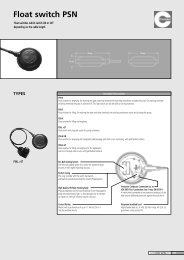
■ Dimensions<br />
C40A<br />
Hard dust-proof cover set (option)<br />
81446083-001<br />
96<br />
(18)<br />
15 159.5<br />
137<br />
12<br />
Mounting bracket<br />
81405411-001<br />
Terminal cover set (option)<br />
81446084-001<br />
Standard terminal base<br />
(Unit: mm)<br />
RDY<br />
REM<br />
MAN<br />
COM<br />
CH1<br />
CH2<br />
CH3<br />
SP<br />
DEV<br />
OUT<br />
1<br />
2<br />
3<br />
4<br />
11<br />
12<br />
13<br />
14<br />
21<br />
22<br />
23<br />
24<br />
26<br />
27<br />
28<br />
29<br />
OUT<br />
EV1 EV2 EV3 OT1<br />
UF1<br />
SP/EV<br />
A/M<br />
R/L<br />
OT2<br />
UF2<br />
PARA<br />
AT<br />
DISP<br />
UF<br />
96<br />
(106 x 104)<br />
5<br />
6<br />
7<br />
15<br />
16<br />
17<br />
25<br />
30<br />
31<br />
32<br />
91.5<br />
LOADER<br />
AT<br />
ENT<br />
8<br />
9<br />
18<br />
19<br />
33<br />
34<br />
10<br />
20<br />
Soft dust-proof cover set (option)<br />
81446087-001<br />
Standard<br />
terminal base<br />
Extension<br />
terminal base<br />
• Extension terminal base<br />
Terminal<br />
screw M3.5<br />
1<br />
26<br />
2<br />
41<br />
49<br />
57<br />
27<br />
3<br />
42<br />
50<br />
58<br />
28<br />
4<br />
43<br />
51<br />
59<br />
29<br />
5<br />
6<br />
44<br />
45<br />
52<br />
53<br />
60<br />
61<br />
30<br />
31<br />
110.5<br />
7<br />
46<br />
54<br />
62<br />
32<br />
8<br />
47<br />
55<br />
63<br />
33<br />
9<br />
48<br />
56<br />
64<br />
34<br />
10<br />
37<br />
98<br />
15<br />
12<br />
(0.5)<br />
(3.2)<br />
1.5<br />
45<br />
90<br />
17<br />
5-3.6 hole<br />
R1.8 + – 0.1<br />
0.2<br />
2.7<br />
16<br />
8<br />
4<br />
6<br />
106<br />
96.6<br />
(96.8)<br />
106<br />
4.7<br />
96.6<br />
1.1<br />
29.5<br />
14<br />
95<br />
98<br />
51.6<br />
69.6<br />
79<br />
5.5<br />
90<br />
13.7<br />
(86)<br />
4.7<br />
106<br />
Soft dust-proof cover set: Part No. 81446087-001<br />
(silicon rubber, transparent)<br />
Terminal cover set: Part No. 81446084-001<br />
This can be fitted to both the standard terminal base and to<br />
the extension terminal base. (construction: incombustible<br />
polyvinyl chloride sheet (gray))<br />
Hard dust-proof cover set: Part No. 81446083-001<br />
(polycarbonate, transparent)<br />
Packing<br />
9
Panel cutout<br />
For standard application or<br />
with soft dust-proof cover<br />
When the hard dust-proof cover<br />
is used<br />
Lateral series mounting<br />
(Unit: mm)<br />
92 +0.8<br />
0<br />
92 +0.8<br />
0<br />
46 (N – 1) x 96<br />
46<br />
150 or more<br />
92 +0.8<br />
0<br />
92 +0.8<br />
0<br />
92 +0.8<br />
0<br />
150 or more<br />
N x 96 – 4<br />
(N: No. of mounted units)<br />
99 or more<br />
107 or more<br />
Standard terminal layout<br />
• AC Model<br />
Instrument power<br />
supply 90 to 264V ac<br />
Event output<br />
GND<br />
EV1<br />
EV2<br />
EV3<br />
1<br />
2<br />
3<br />
4<br />
5<br />
6<br />
7<br />
8<br />
9<br />
10<br />
1a<br />
NO<br />
1a<br />
NO<br />
NO<br />
NC<br />
OPEN<br />
CLOSE<br />
Y<br />
T<br />
G<br />
NO<br />
NC<br />
NO<br />
NC<br />
+<br />
–<br />
+<br />
–<br />
+<br />
–<br />
11<br />
12<br />
13<br />
14<br />
15<br />
16<br />
17<br />
18<br />
19<br />
20<br />
MV1<br />
MV2<br />
*<br />
21<br />
22<br />
23<br />
24<br />
25<br />
COM<br />
RSW1<br />
RSW2<br />
RSW3<br />
RSW4<br />
26<br />
27<br />
28<br />
29<br />
30<br />
31<br />
32<br />
33<br />
34<br />
+<br />
4 to 20mA<br />
–<br />
1 to 5V<br />
+<br />
+<br />
current input<br />
–<br />
RTD input<br />
–<br />
+<br />
Voltage input<br />
–<br />
+<br />
Analog input 2<br />
(remote SP, and internal<br />
cascade models only)<br />
Thermocouple<br />
input<br />
Analog input 1<br />
* Auxiliary output<br />
4 to 20mA<br />
Recorder or other<br />
similar device<br />
* For 2G, 3D, AK, 5K, 9K and BK models,<br />
the auxiliary output terminals are 17 and 18 .<br />
for 0D, 6D and 5G models, the auxiliary output 1 terminals are<br />
14 and 15 , and the auxiliary output 2 terminals are 17 and 18 .<br />
• DC Model<br />
Instrument power supply<br />
21.6 to 26.4 V dc<br />
+<br />
–<br />
GND<br />
Event output<br />
EV1<br />
EV2<br />
EV3<br />
1<br />
2<br />
3<br />
4<br />
5<br />
6<br />
7<br />
8<br />
9<br />
10<br />
1a<br />
NO<br />
1a<br />
NO<br />
NO<br />
NC<br />
OPEN<br />
CLOSE<br />
Y<br />
T<br />
G<br />
NO<br />
NC<br />
NO<br />
NC<br />
+<br />
–<br />
+<br />
–<br />
+<br />
–<br />
11<br />
12<br />
13<br />
14<br />
15<br />
16<br />
17<br />
18<br />
19<br />
20<br />
MV1<br />
MV2<br />
*<br />
21<br />
22<br />
23<br />
24<br />
25<br />
COM<br />
RSW1<br />
RSW2<br />
RSW3<br />
RSW4<br />
26<br />
27<br />
28<br />
29<br />
30<br />
31<br />
32<br />
33<br />
34<br />
+<br />
4 to 20mA<br />
–<br />
1 to 5V<br />
+<br />
+<br />
current input<br />
–<br />
RTD input<br />
–<br />
+<br />
Voltage input<br />
–<br />
+<br />
Analog input 2<br />
(remote SP, and internal<br />
cascade models only)<br />
Thermocouple<br />
input<br />
Analog input 1<br />
* Auxiliary output<br />
4 to 20mA<br />
Recorder or other<br />
similar device<br />
* For 2G, 3D, AK, 5K, 9K and BK models,<br />
the auxiliary output terminals are 17 and 18 .<br />
for 0D, 6D and 5G models, the auxiliary output 1 terminals are<br />
14 and 15 , and the auxiliary output 2 terminals are 17 and 18 .<br />
10
Extension terminal layout<br />
• With RS-485<br />
• With RS-232C<br />
RSW5<br />
RSW6<br />
RSW7<br />
RSW8<br />
RSW9<br />
41<br />
42<br />
43<br />
44<br />
45<br />
EV4 SDA RD<br />
Load 49<br />
57 59<br />
EV5 SDB SD<br />
Load 50 58 60<br />
EV6 RDA SG<br />
Load 51 59 61<br />
EV7<br />
EV8<br />
Load 52<br />
Load<br />
RDB<br />
60<br />
SG<br />
53 61<br />
External<br />
communication<br />
RSW10 46<br />
54<br />
RSW11 47<br />
55<br />
RSW12 48<br />
56<br />
To terminal 25<br />
+ –<br />
External<br />
power<br />
supply<br />
Bias circuit<br />
62<br />
63<br />
64<br />
11
RESTRICTIONS ON USE<br />
This product has been designed, developed and manufactured for general-purpose application in machinery and equipment.<br />
Accordingly, when used in the applications outlined below, special care should be taken to implement a fail-safe and/or redundant<br />
design concept as well as a periodic maintenance program.<br />
• Safety devices for plant worker protection • Start/stop control devices for transportation and material handling machines<br />
• Aeronautical/aerospace machines • Control devices for nuclear reactors<br />
Never use this product in applications where human safety may be put at risk.<br />
Specifications are subject to change without notice.<br />
Advanced Automation Company<br />
International Business Headquarters<br />
Totate International Building<br />
2-12-19 Shibuya Shibuya-ku<br />
Tokyo 150-8316 Japan<br />
URL:http://www.yamatake.com<br />
This has been printed on recycled paper.<br />
(01)<br />
12<br />
Printed in Japan. (H)<br />
1st Edition: Issued in May, 1994<br />
6th Edition: Issued in July, 2003