WayCool 1/3 Hp Evaporative Cooler Manual - Schaefer Ventilation ...
WayCool 1/3 Hp Evaporative Cooler Manual - Schaefer Ventilation ...
WayCool 1/3 Hp Evaporative Cooler Manual - Schaefer Ventilation ...

Create successful ePaper yourself
Turn your PDF publications into a flip-book with our unique Google optimized e-Paper software.
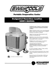
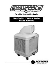
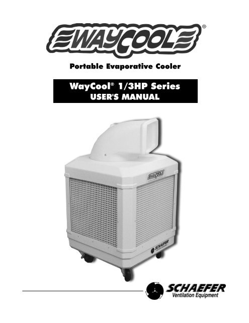
Portable <strong>Evaporative</strong> <strong>Cooler</strong><br />
<strong>WayCool</strong> ® 1/3HP Series<br />
USER'S MANUAL
Table of Contents<br />
INTRODUCTION ............................................................................................................................3<br />
Why use evaporative coolers in your workplace ............................................................................3<br />
How evaporative cooling works ......................................................................................................3<br />
ABOUT THIS MANUAL ..................................................................................................................4<br />
SAFETY INFORMATION ................................................................................................................4<br />
SAFETY RECOMMENDATIONS....................................................................................................5<br />
WC-1/3HP SPECIFICATIONS ........................................................................................................5<br />
WC-1/3HP DESCRIPTION ............................................................................................................6<br />
WATER SUPPLY SYSTEM ........................................................................................................7-8<br />
COOLING PAD ASSEMBLY ..........................................................................................................9<br />
BLOWER AND DUCTWORK ......................................................................................................10<br />
CONTROL ....................................................................................................................................11<br />
OPERATION AND MAINTENANCE ............................................................................................11<br />
Unit placement and other considerations ....................................................................................11<br />
Unpacking and initial setup ..........................................................................................................12<br />
Regular cleaning ..........................................................................................................................13<br />
Normal startup ..............................................................................................................................13<br />
Normal shutdown..........................................................................................................................13<br />
TROUBLESHOOTING..................................................................................................................14<br />
Cooling pads not wetting ..............................................................................................................14<br />
Foaming........................................................................................................................................14<br />
Line clogs or obstructions ............................................................................................................14<br />
Odor Control ................................................................................................................................14<br />
Scale Buildup................................................................................................................................14<br />
Splattering in front ........................................................................................................................14<br />
Leaking from the bottom ..............................................................................................................14<br />
OPTIONS AND ACCESSORIES ..................................................................................................15<br />
Pneumatic wheels ........................................................................................................................15<br />
Water conditioner and cleaner......................................................................................................15<br />
Oscillating spout ..........................................................................................................................16<br />
Automatic shutoff ..........................................................................................................................17<br />
Product Support............................................................................................................................18<br />
Warranty ......................................................................................................................................18<br />
2
Introduction<br />
WHY USE EVAPORATIVE COOLERS IN YOUR WORKPLACE<br />
• The <strong>WayCool</strong> ® evaporative cooler requires little space, has a low initial cost, is inexpensive and simple to<br />
operate and requires minimal scheduled maintenance.<br />
• Due to the design and construction of the cooling pads, cooling efficiency is normally maintained near<br />
optimum throughout the life of the pads (approximately two seasons).<br />
• In many cases, evaporative coolers are a better solution than mechanical refrigeration systems because<br />
they are more economical to operate and maintain, and do not use environmentally sensitive and costly<br />
refrigerants.<br />
HOW EVAPORATIVE COOLING WORKS<br />
Pipe dripping<br />
water onto pads<br />
Wetted cellulose<br />
pads<br />
Warm dry air<br />
greater than<br />
90 deg. F.<br />
Fan<br />
Figure WC-1/3HP.02 - <strong>Evaporative</strong> Cooling Principle<br />
Cool moist air<br />
less than<br />
80 deg. F.<br />
<strong>Evaporative</strong> cooling is the same process your body uses to cool itself. When you perspire, and air moves across<br />
your skin, a portion of the perspiration (water) evaporates. Evaporation requires heat to change liquid water to<br />
water vapor and this heat is taken from your skin, producing the cooling effect.<br />
In an evaporative cooler, the cellulose cooling pads take the place of your skin, water instead of perspiration<br />
wets them and a fan moves the air. The air blows across the cooling pads and evaporates moisture. Heat is<br />
drawn from the pads and the air, dropping the air temperature and producing the cooling effect. The cooled air<br />
is then forced through a building or space and displaces the warm air out of building openings, cooling the<br />
surroundings. In addition, air velocity increases the cooling effect as it moves over the skin of people in the<br />
airflow path.<br />
<strong>WayCool</strong> ® evaporative coolers are portable and use the latest technology to provide large volumes of cool air,<br />
efficiently and inexpensively, for cooling small to medium size areas. Simply add more units to accommodate<br />
larger areas. With proper sizing and application, a <strong>WayCool</strong> ® portable evaporative cooler can lower the effective<br />
air temperature by up to 20 degrees F. Even in high humidity, the efficiency of the <strong>WayCool</strong> ® evaporative cooler<br />
provides effective cooling.<br />
3
About This <strong>Manual</strong><br />
The intent of this manual is to help you in two ways: to provide you with step-by-step instructions for quick and<br />
easy assembly of your product, and to serve as a reference for simple maintenance and questions you may<br />
have regarding your product.<br />
Read ALL instructions carefully before starting your <strong>WayCool</strong> ® . Pay particular attention to all SAFETY<br />
information.<br />
Optional equipment contains necessary instructions for assembly and/or operation.<br />
The <strong>WayCool</strong> ® <strong>Evaporative</strong> <strong>Cooler</strong> is labeled with a serial number. The serial number is located<br />
inside the unit on the aluminum frame, behind the switch. Removal of the serial number label will<br />
void all warranties.<br />
All information, illustrations and specifications in this manual are based on the latest product information<br />
available at the time of printing. Product specifications subject to change. We reserve the right to make changes<br />
at any time without notice.<br />
Safety Information<br />
Warning and Danger Decals have been placed on the equipment to warn of potentially dangerous situations.<br />
Care should be taken to keep this information intact and easy to read at all times. Replace missing or damaged<br />
safety decals immediately. The diagram below shows the proper location of the safety decals as shipped from<br />
the factory.<br />
Start Unit -Turn water pump on 5-10<br />
minutes before running blower to wet<br />
evaporative cooling pads.<br />
Shut Down -Turn pump off and run only<br />
blower until evaporative cooling pads are dry.<br />
This prolongs the life of the pads.<br />
WARRANTY- VOID IF YOU RUN THE<br />
PUMP WITHOUT WATER.<br />
CAUTION - ALWAYS TURN OFF AT<br />
SWITCH AND DISCONNECT POWER<br />
BEFORE REMOVING EVAPORATIVE<br />
COOLING PADS FOR CLEANING OR<br />
INTERNAL MAINTENANCE.<br />
CLEANING- Clean pads a minimum of once<br />
every two weeks. Remove pads from unit<br />
and clean with garden hose only. DO NOT<br />
use chemicals or high pressure hose.<br />
WARNING!<br />
Interference with the oscillating spout while the unit is operating,<br />
or manually directing the oscillating spout, will cause damage to<br />
the gear motor. Keep oscillating path clear of obstructions.<br />
This warning decal is<br />
found on the top of<br />
oscillating units only.<br />
Using the equipment for purposes other than specified in this manual may cause personal injury and/or damage<br />
to the equipment.<br />
Safety Alert Symbol<br />
This is a safety alert symbol. When you see this symbol on your equipment, be alert to the potential<br />
for personal injury. This equipment is designed to be installed and operated as safely as possible;<br />
however, hazards do exist.<br />
Signal Words are used in conjunction with the safety alert symbol to identify the severity of the warning.<br />
CAUTION indicates an imminently hazardous situation, which, if not avoided, COULD cause damage to your<br />
equipment or equipment failure.<br />
WARNING indicates a potentially hazardous situation, which, if not avoided, COULD result in death or serious<br />
injury.<br />
4
Safety Recommendations<br />
READ AND SAVE THESE INSTRUCTIONS!<br />
• This is an electric device with moving components. There is the possibility of fire, electric shock or injury to<br />
persons. Ensure all the safety recommendations are adhered to in order to minimize this risk.<br />
• Disconnect all power and unplug the unit before you inspect, clean or perform maintenance on the<br />
components of the unit.<br />
• Never reach into the unit when it is running; you could become entrapped by the V-belt or injured by the<br />
rotating fan blades.<br />
• The metal frame edges are sharp; don't run your hand along them. Be careful and wear gloves when you<br />
reach under the frame to inspect the PVC pipes and mesh socks.<br />
• A GFCI (Ground Fault Circuit Interrupter) is recommended for use with this product.<br />
• If pads and grates are removed for servicing, they must be replaced prior to operating the unit.<br />
PLEASE NOTE<br />
• Minimum inlet pressure is 10 PSI; maximum inlet pressure is 100 PSI.<br />
• Never leave unit unattended while in operation.<br />
• Height and Width - 25" x 25" wide x 42" high<br />
(with casters and directional spout).<br />
Actual WC-1/3HP <strong>WayCool</strong> ®<br />
varies slightly from unit<br />
• Shipping Weight - 130 pounds. shown here.<br />
• Blower - double-inlet centrifugal.<br />
• Motor - 1/3 HP, 115V, 2 speed, 60 Hz<br />
(also available in 230V and 50 Hz).<br />
• Pump - submersible, vane type, 210 GPH<br />
(gallons per hour).<br />
• Pump Filter - washable polyethylene filter.<br />
• Pump Discharge Filter - 480 micron stainless<br />
steel.<br />
WC-1/3HP Specifications<br />
• Reservoir Capacity - 14 gallons.<br />
Figure WC-1/3HP-04.<strong>WayCool</strong> ® <strong>Evaporative</strong> <strong>Cooler</strong> Overview<br />
• Optional Water Supply - standard 3/4" hose connection (garden hose size).<br />
• Housing - high impact ABS plastic wit UV protection.<br />
• Evaporation Media - chemically treated cellulose paper.<br />
5
WC-1/3HP Description<br />
The <strong>WayCool</strong> ® evaporative cooler is a completely self-contained, portable unit capable of delivering 25.5 MPH<br />
velocity of air with a temperature drop of up to 20 degrees F. The unit is composed of:<br />
• Level-controlled water supply system<br />
• Cooling pad assembly<br />
• Motor-driven blower and ductwork<br />
• Controls<br />
• Frame and housing<br />
The reservoir is made of high impact ABS plastic and holds approximately 14 gallons at normal operating level<br />
(about 4" deep).<br />
A float-operated valve automatically maintains proper water level when the unit is connected to a water supply.<br />
The reservoir rests on, and is fixed to, an aluminum cradle. The reservoir, in turn, is secured to the aluminum<br />
frame. Four casters (two locking, two non-locking) are attached to the underside of the aluminum cradle.<br />
A pump draws water from the reservoir and discharges it through the vinyl hose to the PVC pipes located above<br />
the cooling pads. The PVC pipes distribute water onto the top of the cooling pads; saturating them. Excess<br />
water drips back into the reservoir through the holes in the cooling pad support channels.<br />
The cellulose cooling pads sit in support channels and are held in place by plastic retaining grates. The grates<br />
also help prevent damage to the cooling pads. Two pad sections fit in each side of the unit (total eight sections)<br />
to totally enclose the unit.<br />
The blower is hung from the top of the frame and powered by a direct-drive 1/3HP electric motor. The blower<br />
draws room air through the cooling pads where it picks up moisture and cools by evaporation. The blower then<br />
discharges the cooled air through the spout.<br />
It is important the cooled space has sufficient air openings so the warmer air can flow out and be<br />
replaced by the cooled air. A closed-in space or high humidity will reduce the cooling effect. See UNIT<br />
PLACEMENT AND OTHER CONSIDERATIONS in the "Operation and Maintenance" section.<br />
A screen covers the discharge duct to prevent foreign objects from entering the blower. A threaded rod screws<br />
through a threaded brace above the screen to hold the spout in position. A plastic knob secures the spout to the<br />
rod. The spout is made of a tough, durable plastic and can be manually rotated 360 degrees to provide cool air<br />
in any direction without moving the unit.<br />
Water weighs about eight pounds per gallon, so when the unit is full it weighs over 240 pounds. During<br />
setup and before startup, place the unit in the desired location and then fill the reservoir. Do not attempt<br />
to lift the unit once it is filled and be careful to avoid spills when moving it, even over smooth ground.<br />
Do not try to push it over rough or soft ground as you can overstress the wheels and frame and cause<br />
structural and component damage, which is not covered by warranty.<br />
6
Water Supply System<br />
Actual WC-1/3HP <strong>WayCool</strong><br />
Actual WC-1HP<br />
®<br />
varies slightly<br />
<strong>WayCool</strong> ® from unit<br />
shown here.<br />
varies slightly<br />
from unit shown here.<br />
Figure WC-1/3HP.05 - Water Supply System<br />
The reservoir can be supplied continuously with an ordinary garden hose by attaching the supplied hose adapter<br />
(see Figure WC-1/3HP.07) to the fill connection, or it can be filled manually.<br />
With a continuous water supply connected, the float valve in the reservoir (like the one in your toilet tank) rises<br />
and falls with the water level. A linkage attaches the float to the shutoff valve in the fill connection. As the water<br />
level rises to normal operating level (about 3" deep), the float valve shuts off the water supply. When the water<br />
level drops, the float valve reopens to maintain a normal operating level.<br />
After unplugging the unit, the reservoir can also be manually filled with a hose or bucket, if a hose connection is<br />
impractical. Simply remove any of the plastic retaining grates and one of the cooling pad sections and place the<br />
hose, or pour the water, directly into the reservoir. When you fill the reservoir manually it can be filled to a higher<br />
level, but make sure someone monitors the filling operation to avoid overfilling and flooding.<br />
Water damage due to overfilling is not covered by the warranty.<br />
When you run the unit and fill it manually, check the water level frequently so it does not run dry.<br />
Operating the pump without water will damage it or reduce its service life. This is not covered by the<br />
warranty. The cooling effect also stops if the pads dry.<br />
Pads and grates must be replaced before operating unit.<br />
7
Water Supply System cont'd<br />
A drain in the reservoir allows you to drain the unit for cleaning and maintenance. A drain cap on the underside<br />
of the aluminum tray covers the drain during operation. Make sure the cap is in place before you fill the<br />
reservoir. The drain cap should be finger-tightened only.<br />
The pump is attached to a bracket, which in turn is fixed to the blower housing. The bracket holds the pump in<br />
its proper position on top of the foam filter and slightly above the bottom, allowing sufficient space for water to<br />
enter the pump suction.<br />
The pump can be easily removed and replaced with the services of a qualified electrician.<br />
Pump impeller<br />
Plastic screen<br />
Figure WC-1/3HP.06 - Pump<br />
A small plastic screen covers the pump inlet to prevent foreign matter from entering and damaging the pump<br />
impeller. The screen snaps in place and can be easily removed for inspection or cleaning.<br />
The pump sits on a foam filter; somewhat like a sponge. The filter traps dirt that could enter the water<br />
distribution system and build up on the cooling pads, reducing their effectiveness. Dirt could also accumulate in<br />
the PVC pipes and plug up the spray holes.<br />
The pump discharges through a fine screen washable filter which decreases the contamination of the cooling<br />
pads and water system. The discharge filter casing is a clear plastic so dirt buildup on the internal screen is<br />
easily visible. As dirt builds up, water flow to the cooling pads is reduced and performance decreases. The clear<br />
filter housing is threaded and screws into the filter body for easy removal to access the screen.<br />
A dirty water supply will quickly reduce the unit's performance and the unit will require more frequent<br />
cleaning to maintain cooling effectiveness. Always try to use a filtered, treated water supply.<br />
A clear vinyl hose connects the pump to the filter. From the filter, a "T" connector supplies two lines that run<br />
along the bottom and up opposite frame corners to supply the PVC pipe with water. Each vinyl hose connects to<br />
two PVC pipes which run horizontally along the top of the frame above the cooling pads.<br />
The PVC pipes have a series of holes that run the full length of the pipe. Each PVC pipe is covered with a<br />
plastic mesh sock which helps break up the water as it leaves the spray holes. This gives a more even water<br />
distribution across the cooling pad and reduces splashing. The holes direct the water inward at a 90° angle to<br />
continuously saturate the cooling pads from the top down. Excess water drains back to the reservoir through<br />
drainage holes in the bottom support channels which support the cooling pads.<br />
Water cleanliness has a major effect on the cooler's performance. Use a clean water supply and<br />
consider a water softener if your water is hard. Dissolved solids in hard water deposit on the cooling<br />
pad surfaces and reduce the airflow through the unit and therefore the amount of evaporation.<br />
8
Cooling Pad Assembly<br />
The cooling pads are critical for proper, efficient cooler operation. They are made of laminated cellulose (paper)<br />
fibers and arranged to give a large surface area for evaporation and to provide a rigid structure. The shape of<br />
the cells allows high velocity airflow through the pad at a minimum pressure drop. At the same time, the air<br />
passages between the cells force the incoming air to impinge on the wet cell surfaces and maximize<br />
evaporation.<br />
The <strong>WayCool</strong>® evaporative cooler also acts as an air filter and removes dust and other particles from<br />
the air. This dirt collects on the cooling pads and lowers cooler efficiency. The pads should be cleaned<br />
at least weekly and more frequently in dusty conditions. See Regular Cleaning under "Operation &<br />
Maintenance."<br />
The pump supplies a continuous flow of water over the pads causing a "sheet flow" which constantly replaces<br />
the water lost to evaporation and keeps the pads saturated.<br />
One cubic foot of the cooling pad material holds about a gallon of water during operation. One cubic meter<br />
holds about 100 liters of water.<br />
The cooling pads are relatively strong but are subject to crushing, especially when wet. Always run the<br />
unit with the plastic retaining grates in place and handle them carefully when you clean them. Crushed<br />
cells reduce the total airflow through the unit and therefore lowers it's cooling capacity.<br />
The cooling pad sections (two sections per side, eight sections total) are held by metal channels at the top and<br />
bottom of the unit. The channels hold the cooling pads in position and form four sidewalls to completely enclose<br />
the unit.<br />
The top channels house the PVC pipe, which run horizontally along the channel directly above the cooling pads.<br />
The bottom channels have a series of holes drilled through them to allow excess water flowing down the cooling<br />
pads to return to the reservoir.<br />
The plastic retaining grates fit in front of the cooling pads and sit in the same channels as the pads; holding<br />
them in place and protecting them from accidental damage. The plastic grates and cooling pads are easily<br />
removed by placing a flat blade under the bottom and lifting upwards, then outwards. Once one pad is removed,<br />
the others can be lifted up and out by hand without using a blade.<br />
Do not remove or handle the cooling pads when they are wet, as they damage easily. Run the blower<br />
without the pump until pads are dry. With normal care, the pads should last at least two seasons. Abuse<br />
or mishandling will reduce their effectiveness and shorten their life.<br />
9
Blower and Ductwork<br />
Actual WC-1/3HP <strong>WayCool</strong> ®<br />
varies slightly from unit<br />
shown here.<br />
Figure WC-1/3HP.07 - Fan Blower<br />
The <strong>WayCool</strong> ® WC-1/3HP uses a direct-drive, 1/3 HP electric motor to drive a centrifugal blower. The blower<br />
draws room air through the cooling pads and discharges the cooler air through the spout, displacing the warmer<br />
air with cooler air and decreasing the temperature.<br />
The blower is secured to the top of the frame and hangs upside down to direct the air out the top of the unit.<br />
Brackets on each side of the blower casing secure the blower to the frame and hold it in position.<br />
The electric motor is secured to the blower casing by metal braces and connects directly to the blower shaft. A<br />
startup capacitor is attached to the top of the blower casing and is wired to the motor.<br />
A capacitor retains electrical energy even after the unit is shut down and unplugged. DO NOT TOUCH<br />
the bare connections or you could be injured.<br />
The power cord runs down the frame leg that has the control switch on the outside. It exits the frame leg at the<br />
bottom and has a male plug that must be plugged into a normal 120 volt outlet. The cord is approximately seven<br />
feet long.<br />
The WC-1/3HP unit requires 120 volts and 5 amps of power. This is normally available on most circuits.<br />
However, if you are running a number of other items on the same circuit, you may trip the breaker. If so,<br />
plug the <strong>WayCool</strong> ® into another circuit. If you require an extension cord, make sure it is at least #14 wire<br />
and no longer than 50 feet. If you need a longer cord, use one with # 12 wire. Using smaller wire or a<br />
longer cord will degrade the <strong>WayCool</strong> ® 's performance, shorten the life of the electric motor and could<br />
cause a fire. None of this is covered by warranty.<br />
A GFCI (Ground Fault Circuit Interrupter) is recommended for use near water.<br />
10
Control<br />
The <strong>WayCool</strong> ® WC-1/3HP control switch is mounted on the outside of one frame leg.<br />
It has the following positions:<br />
OFF - Power is off to the blower motor and the pump motor.<br />
LOW VENT - The blower runs at low speed and the pump is OFF.<br />
HIGH VENT - The blower runs at high speed and the pump is OFF.<br />
Use this setting to quickly dry the cooling pads for removal and cleaning.<br />
LOW COOL - The blower runs at low speed and the pump is on.<br />
Use this setting for low cooling loads.<br />
HIGH COOL - The blower runs at high speed and the pump is on.<br />
Use this setting for maximum cooling.<br />
PUMP ONLY - Pump is on and the blower is off. Use this<br />
setting during startup to first saturate the cooling pads,<br />
then switch to LOW COOL or HIGH COOL to begin cooling.<br />
Figure WC-1/3HP.08 - <strong>WayCool</strong> ® Control Switch<br />
Operation and Maintenance<br />
UNIT PLACEMENT AND OTHER CONSIDERATIONS<br />
The <strong>WayCool</strong> ® unit(s) should be placed at one end of<br />
the building and an appropriate exhaust fan should be<br />
at the opposite end to pull the cool air from the<br />
<strong>WayCool</strong> ® unit and discharge the warm air out of the<br />
building.<br />
Try to get all the air flowing in the same direction. Do<br />
not direct other fans against the <strong>WayCool</strong> ® unit. It will<br />
counter the <strong>WayCool</strong> ® 's airflow and stop the cooling<br />
effect.<br />
Obstructing the airflow from the <strong>WayCool</strong> ® unit severely<br />
reduces the cooling effect.<br />
Avoid using ceiling fans as they disrupt the airflow from<br />
the <strong>WayCool</strong> ® unit.<br />
Use as many exhaust fans as possible to create a<br />
natural draft through the building. This will enhance the<br />
performance of the <strong>WayCool</strong> ® (s).<br />
Figure WC-1/3HP.09 - Typical <strong>WayCool</strong> ® Unit Arrangement<br />
11
Operation and Maintenance cont'd<br />
UNPACKING AND INITIAL SETUP<br />
The <strong>WayCool</strong> ® WC-1/3HP <strong>Evaporative</strong> <strong>Cooler</strong> is shipped upright in a corrugated container. The unit is fully<br />
assembled and ready for service except for thoroughly cleaning manufacturing dust from the cooling pads<br />
before running it for the first time.<br />
CAUTION Be careful when you move the unit while it is in the shipping container and when<br />
moving it around with the container removed. Avoid jarring or dropping the unit.<br />
1. With the unit in the upright position as marked on the container, use a sharp knife or scissors to cut the<br />
banding material on the shipping container.<br />
Do not discard the shipping container until you have thoroughly inspected the unit.<br />
2. Remove the shipping container. Inspect the entire unit for shipping damage.<br />
3. Ensure the switch is OFF and the unit is unplugged.<br />
4. Remove the plastic retaining grates from all four sides of the unit. Use your fingers<br />
to lift each upward, then outward from the bottom.<br />
5. Remove the cooling pads from all four sides of the unit. Place a putty knife or large<br />
flat-blade screwdriver under the pad to lift it up, then outward. With one pad out,<br />
the rest can be easily removed by placing one hand on the pad's inside, your other<br />
hand on the outside and lifting the pad up and out from the bottom<br />
(see Figure WC-1/3HP.10 - Pads).<br />
6. Remove cardboard from blower.<br />
Figure WC-1/3HP.10 - Pads<br />
7. Look for cracks in the bottom near the frame legs. This is also an indication of rough handling.<br />
8. Ensure the frame legs are straight and in alignment, and that the blower is sitting level and in proper<br />
position.<br />
If you notice any damage to your unit, immediately contact the dealer where it was purchased.<br />
9 Thoroughly clean all eight cooling pad sections using a garden hose.<br />
Do not use cleaning fluids or other chemicals to clean the pads as they can cause foaming during<br />
operation. Use only clean water. Refer to page 15 for approved cleaners.<br />
10. Remove the drain cap from the underside of the reservoir and rinse with a hose to flush any manufacturing<br />
dust etc. from the unit. Replace the drain cap.<br />
11. Replace the pads and the protective retaining grates.<br />
12. Proceed to NORMAL STARTUP.<br />
12
Operation and Maintenance cont'd<br />
REGULAR CLEANING<br />
The frequency with which the <strong>WayCool</strong> ® should be cleaned will depend on the environment in which it is used. The more dirty<br />
the environment the more often it will need cleaning. In most cases the <strong>WayCool</strong> ® will need to be cleaned weekly.<br />
CAUTION The pads should be dry before you handle them, as they are stronger when dry than when they are<br />
wet and less susceptible to damage. If they are wet, run the unit in the HIGH VENT position until they are dry.<br />
After cleaning, let the pads air dry before you replace them.<br />
1. Turn the switch to OFF and unplug the unit.<br />
2. Remove the plastic retaining grates and check the pads for cleanliness. If they are dirty, remove and clean by spraying with<br />
a garden hose (water only). If they are not dirty you will still need to remove the cooling pads to clean the inside of the unit.<br />
Dirty cooling pads reduce the unit's effectiveness.<br />
3. Use a garden hose to rinse out the bottom and the inside of the unit. The dirt that accumulates is removed from the air<br />
during operation, as the <strong>WayCool</strong> ® unit also acts as an air filter.<br />
4. Remove the drain cap from the underside of the unit and let it unit drain completely. Rinse out any remaining dirt.<br />
5. Replace the drain cap (finger tighten only).<br />
6. Remove the pump discharge filter by unscrewing the top, removing the screen and rinsing it with a hose or under a tap.<br />
Replace the filter screen and screw the top back on.<br />
7. Remove the pump filter from underneath the pump. Wash thoroughly with a hose. Compress filter and place back under the<br />
pump.<br />
8. Replace the cooling pads once they are dry and re-install the plastic retaining grates.<br />
With proper use and regular cleaning, the cooling pads will last about two seasons. If you handle them wet and are<br />
abusive, however, they will be easily damaged. Refer to page 15 for recommended conditioning and cleaning<br />
chemicals.<br />
NORMAL STARTUP<br />
1. Place the unit where it will be run. Do not attempt to lift or move the unit once it is filled. Damage to the unit or a large spill<br />
may occur.<br />
When you decide where to place the unit, make sure there are no obstructions that could disrupt or block the airflow.<br />
Make sure the unit is level at all times. Keep the unit at least three feet away from walls or other obstructions that will<br />
interfere with airflow into the unit.<br />
2. Check the drain cap to be sure it is in place and secure.<br />
3. Connect the garden hose to the brass hose adapter. Be sure there is a washer in the female end of the hose connection.<br />
4. Open the water supply valve and be sure water enters the reservoir through the float valve by removing one cooling pad on<br />
the side with the water connection. Allow the unit to fill and be sure the float valve shuts off the water completely.<br />
5. If you are filling the unit manually, remove one or more cooling pads and fill the reservoir with a bucket or hose.<br />
6. Monitor the filling operation to avoid overflowing and damage.<br />
7. Plug the unit into an outlet.<br />
8. Adjust the spout to discharge cool air in the desired direction and tighten the knob on the end of the threaded rod.<br />
9. Turn the switch to the PUMP ONLY position and let it run for 5 - 10 minutes to saturate the cooling pads. Check that the<br />
pads are saturated completely and there are no dry spots.<br />
CAUTION Do not run the pump without water in the reservoir or you will damage the pump. Running the<br />
pump dry will void the warranty on the pump.<br />
10. Turn the switch to the HIGH COOL or the LOW COOL position to begin normal cooling operation.<br />
NORMAL SHUTDOWN<br />
1. Turn the switch to the HIGH VENT position and let the unit run until the cooling pads are dry. This will maximize the life of<br />
the pads.<br />
2. Turn the switch to the OFF position. Unplug the unit if you are going to clean the pads or inspect the components.<br />
3. Shut off the water supply.<br />
4. Drain the reservoir if you are going to clean or store the unit.<br />
5. If the unit will be stored for the season, ensure the cooling pads are completely dry, and then remove them. Wrap them in<br />
plastic bags or store them in a clean place where they will not be damaged or get dirty. The unit should be cleaned<br />
thoroughly before storing.<br />
13
Troubleshooting<br />
COOLING PADS NOT WETTING<br />
1. Ensure there is water in the reservoir.<br />
2. Ensure the motor switch is in the START position and the pump switch is in the ON position.<br />
3. Ensure the pump is running.<br />
4. Pump is running but no water:<br />
a. Ensure hose is connected.<br />
b. Inspect and clean the pump discharge filter.<br />
c. Inspect and clean the pump intake filter.<br />
d. Ensure the impeller on the inside of the pump turns freely (see Figure WC-1/3HP.06 - Pump).<br />
5. Pump is not running:<br />
a. A certified electrician must check the wiring from pump to pump selector switch.<br />
b. If the wiring is correct, replace the pump.<br />
FOAMING<br />
Foaming is generally caused by a dirty water supply or contaminated water in the reservoir.<br />
1. If foaming occurs, stop the unit, drain it and flush the bottom and inside thoroughly with clean water.<br />
2. Clean the pads and do not use any kind of chemical cleaner. Refer to the REGULAR CLEANING section for the proper<br />
procedure for cleaning the pads.<br />
3. Re-assemble, refill the reservoir and restart.<br />
LINE CLOGS OR OBSTRUCTIONS (little or no water flow)<br />
Depending on the cleanliness of the water and the amount of dirt, dust, etc. in the air, you may have to clean the PVC pipes<br />
from time to time. Your own experience will dictate the frequency.<br />
1. Turn off and unplug the unit.<br />
2. Remove the plastic knob from the threaded rod in the spout.<br />
3. Remove the spout and set it aside.<br />
4. Remove the two screws that hold the top cover on the unit.<br />
5. Remove the top cover and set it aside.<br />
6. Locate the four PVC pipes in the top metal channel. Each PVC pipe is secured to the Y connector by a single screw.<br />
Remove this screw from all four PVC pipes.<br />
7. Grip the opposite end of each PVC pipe with pliers and gently twist it out of its Y connector.<br />
8. Remove the plastic mesh socks from the PVC pipes and clean them in warm, soapy water.<br />
9. Direct a jet of water at the series of outlet holes in the PVC pipes to blow them clear.<br />
10. Direct the water nozzle into the end of each pipe and blow them clear. Inspect them for cleanliness and repeat if necessary.<br />
11. Re-install the socks over the PVC pipes, taking care not to bunch them.<br />
12. Replace the PVC pipes, taking care to ensure the water outlet holes are facing inward at 90°. There is a mark on the PVC<br />
pipe that indicates the position of the holes.<br />
Be sure you push the PVC pipes fully into the Y connectors so the retaining screws go through the connector and the<br />
pipe to hold them in.<br />
ODOR CONTROL<br />
Ensure water source is of good quality and regular maintennace is being conducted. <strong>WayCool</strong> ® Water Conditioner is available<br />
from the manufacturer. See page 15.<br />
LIME OR SCALE BUILDUP<br />
Ensure water source is of good quality and regular maintennace is being conducted. <strong>WayCool</strong> ® Water Conditioner is available<br />
from the manufacturer. See page 15.<br />
SPLATTERING IN FRONT<br />
See LINE CLOGS OR OBSTRUCTIONS.<br />
LEAKING FROM THE BOTTOM<br />
Check for cracks In the reservoir. If a crack is found, repair it by using a <strong>WayCool</strong> ® Repair Kit or replace the entire bottom.<br />
See ORDERING REPLACEMENT PARTS on page 18.<br />
14
Options and Accessories<br />
Your <strong>WayCool</strong> ® <strong>Evaporative</strong> cooler can be purchased with certain option and/or accessories, and some of these<br />
can be retrofitted to your <strong>WayCool</strong> ® after the initial purchase. Instructions are included with all equipment<br />
purchased separately from your <strong>WayCool</strong> ® .<br />
Options available at time of purchase only:<br />
• Oscillating Spout<br />
Options and accessories available at time of purchase or after purchase:<br />
• Pneumatic Wheels<br />
• Automatic Shutoff<br />
• Water Conditioner and Cleaner<br />
PNEUMATIC WHEELS<br />
Pneumatic wheels are available at the time of purchase or as a retrofit kit on a<br />
previously purchased <strong>WayCool</strong> ® .<br />
The pneumatic wheel option includes two locking and two non-locking wheels.<br />
Pneumatic wheels are designed to allow for easier rolling on rough or uneven surfaces.<br />
WATER CONDITIONER<br />
<strong>WayCool</strong> ® Water Condition<br />
is recommended to control<br />
odors found to be present<br />
in some water sources.<br />
• Place the tab under the<br />
float valve water outlet for<br />
fast, effective odor control.<br />
• Place the tab next to the<br />
pump for longer lasting<br />
odor control.<br />
CLEANER<br />
<strong>WayCool</strong> ® Cleaner is recommended to<br />
remove scale buildup from the water<br />
supply system.<br />
• Follow the instructions on page 13 to<br />
clean the unit. Refill with water and add<br />
one pint of <strong>Cooler</strong> Cleaner Treatment<br />
to the reservoir. Operate the <strong>WayCool</strong> ®<br />
in PUMP ONLY mode for approximately<br />
20 minutes.<br />
• Drain, clean and refill the <strong>WayCool</strong> ®<br />
with fresh water. Repeat steps if<br />
necessary. Repeat treatment when<br />
scale buildup becomes evident.<br />
15
Options and Accessories cont'd<br />
OSCILLATING SPOUT<br />
The oscillating spout is operated<br />
by a four RPM gear motor that<br />
delivers 50 in/lbs. in torque. As<br />
the gear motor rotates, the spout<br />
oscillates in a 110-degree arc,<br />
which cools an area of about<br />
9500 square feet.<br />
Oscillator Switch<br />
On/Off Switch<br />
Oscillator Assembly<br />
The design of the oscillator requires the blower duct to sit loosely on top of the unit. Do not tighten it down.<br />
Do not place hands or any other object in the spout while unit is operational!<br />
Do not attempt to stop spout from oscillating!<br />
IF UNIT DOES NOT OSCILLATE<br />
1. Ensure the unit is plugged into a standard 120-volt outlet.<br />
2. Ensure the oscillator switch is in the ON position.<br />
3. Ensure the gear motor is running. To do this, shut off the unit by turning the main switch to the OFF position<br />
and leave the rocker switch for the gear motor in the ON position. You should then be able to hear the gear<br />
motor.<br />
4. If the motor is running:<br />
• The spout may be fastened too tight against the top of the <strong>WayCool</strong> ® . The nut above the brace should<br />
be loosened to allow 1/16" clearance between the bottom of the spout and the top of the <strong>WayCool</strong> ® .<br />
• If the spout is not too tight, the linkage may be damaged. Look for visible damage to the linkage rod or<br />
the lever. If any of the linkage parts are damaged, they will need to be replaced.<br />
5. If the motor is not running, the motor may have failed or there could be a wiring problem. Contact a licensed<br />
electrician. If the motor is determined to have failed, it must be replaced.<br />
IF SPOUT APPEARS TO JUMP WHILE OSCILLATING<br />
1. The spout may be fastened too tight against the top of the <strong>WayCool</strong> ® . The nut above the brace should be<br />
loosened to allow 1/16" clearance between the bottom of the spout and the top of the <strong>WayCool</strong> ® .<br />
2. If the spout is not too tight, the linkage may be damaged. Look for visible damage to the linkage rod or the<br />
lever. If any of the linkage parts are damaged, they will need to be replaced.<br />
IF UNIT MAKES EXCESSIVE NOISE<br />
1. The spout may be fastened too tight against the top of the <strong>WayCool</strong> ® . The nut above the brace should be<br />
loosened to allow 1/16" clearance between the bottom of the spout and the top of the <strong>WayCool</strong> ® .<br />
2. If the spout is not too tight, the linkage may be damaged. Look for visible damage to the linkage rod or the<br />
lever. If any of the linkage parts are damaged, they will need to be replaced.<br />
3. A motor bearing may have failed. If the noise is determined to be coming from the motor, the bearing may<br />
have failed and the motor may need to be replaced.<br />
IF SPOUT LIFTS UP OUT OF RECESS IN TOP OF UNIT<br />
1. The spout may be too loose. There should be approximately 1/16" clearance between the blower duct and<br />
the top of the <strong>WayCool</strong> ® .<br />
2. The linkage may be damaged. Look for visible damage to the linkage rod or the lever. If any of the linkage<br />
parts are damaged, they will need to be replaced.<br />
WARNING If the top of the unit is removed for troubleshooting or for any other reason, the<br />
wires from the gear motor to the oscillator switch must first be disconnected. This is done by<br />
removing the two female disconnects that are attached to the back of the oscillator switch.<br />
16
Options and Accessories cont'd<br />
AUTOMATIC SHUTOFF<br />
The Automatic Shutoff Option is available at the time of<br />
purchase or as a retrofit kit on a previously purchased<br />
<strong>WayCool</strong> ® .<br />
The automatic shutoff turns off the pump when the water level<br />
reaches a low point and protects the pump from damage. The<br />
warranty on the pump is void if it is run dry.<br />
WIRING INSTRUCTIONS<br />
1. Turn off unit and unplug from power source.<br />
2. Remove spout.<br />
3. Remove the two #2 square headed screws from the top<br />
of the unit and remove the top.<br />
4. Unplug the pump and motor at the top of the electrical corner.<br />
5. Remove the two #2 square headed screws from the electrical corner and remove the corner.<br />
6. Remove the paper from the double-faced tape on the back of the relay. Stick the relay to the aluminum frame on the inside<br />
of the electrical corner approximately 5" from the top of the frame; ensuring the terminals are pointing downward (see<br />
diagram).<br />
7. Remove the grate and pads from the side of the unit to the left of the electrical corner.<br />
8. Utilizing the electric screwdriver and the 5/16" hex head bit, attach the supplied pump brace to the blower with the two<br />
self-tapping screws from the hardware bag. This should be done in the same manner as the pump is attached, but place it<br />
on the left side of the blower and ensure the bottom of the brace is 2" from the bottom of the reservoir.<br />
9. The float switch is already attached to the supplied pump brace with an 8" cable tie. Ensure there is 3" of cord from the right<br />
side of the pump brace to the float and that the float does not hit the frame (see diagram). Do not remove cable tie from<br />
pump brace.<br />
10. Run the cord for the float switch up through the bottom of the aluminum frame on the electrical corner.<br />
11. Remove the cord connector. It is located at the bottom of the electrical corner.<br />
12. Drill a 31/64" hole in the electrical corner approximately 7/8" below the switch, and insert the indicator light into the hole<br />
(see diagram).<br />
13. Place the female disconnect on the indicator light labeled L1 on Post 5 of the relay.<br />
14. Remove the blue spade connector and wire from the L position on the switch with a Phillips head screwdriver, and insert the<br />
spade connector from the jumper labeled A into the L position on the switch.<br />
15. Cut the black wire from the power cord just below the blue connector and then strip 1/2" of plastic from the black wire.<br />
16. Twist the bare end of this wire together with the L2 wire from the indicator light, the A jumper from the switch, and the<br />
jumper labeled B that comes from Post A on the relay. Connect all four of these wires together with a red wire nut from the<br />
hardware bag.<br />
17. Unscrew the yellow wire nut that is on the three white wires, and separate the white wire that goes to the pump pigtail and<br />
attach the female disconnect from the hardware bag to this wire. Place this disconnect on Post 2 on the relay.<br />
18. Twist the white wire from the power cord, the white wire from the motor cord, the wire labeled F2 on the float switch, and<br />
the jumper labeled C from Post 7 on the relay all together and connect all four of them with a red wire nut from the<br />
hardware bag.<br />
19. Connect the female disconnect that is attached to the wire labeled F1 on the float switch to Post B on the relay.<br />
20. Re-install the cord connector into the electrical corner.<br />
21. Place the electrical corner back into the bottom, but do not re-attach with the screws.<br />
22. Plug the pump and motor in and test the operation of the float switch.<br />
23. Place the two #2 square headed screws into the electrical corner.<br />
24. Place the top back on the unit and re-insert the two #2 square headed screws.<br />
25. Place the spout back on the unit and secure it with the top knob.<br />
If the pump does not turn off:<br />
• Ensure wiring is done properly.<br />
• Ensure the float switch is at an acceptable depth.<br />
If the pump turns off too soon:<br />
• Ensure the float switch is at an acceptable depth.<br />
• Ensure water is at least three to five inches deep.<br />
17
Product Support<br />
Using this equipment for any other purpose than it was intended or in a way not within the operating<br />
recommendations specified in this manual will void the warranty and may cause personal injury.<br />
This manual is designed to provide comprehensive planning, installation, safety, operation, maintenance,<br />
troubleshooting and parts information. The Table of Contents provides a convenient overview of the information<br />
in this manual.<br />
Thank You<br />
The employees of <strong>Schaefer</strong> <strong>Ventilation</strong> Equipment would like to thank you for your recent purchase. If a problem<br />
should arise, your <strong>Schaefer</strong> dealer can supply the necessary information to help you.<br />
Dealer Contact and Product Information<br />
Dealer’s Name __________________________________________________________________________________<br />
Dealer’s Address<br />
________________________________________________________________________________<br />
______________________________________________________________________________________________<br />
Dealer’s Phone __________________________________________________________________________________<br />
Date of Purchase ________________________________________________________________________________<br />
Serial Number<br />
__________________________________________________________________________________<br />
Ordering Replacement Parts<br />
To order replacement parts contact the dealer from whom you purchased your <strong>WayCool</strong> ® . If you do not have<br />
that information, please call <strong>Schaefer</strong> <strong>Ventilation</strong> Equipment at 800-779-3267 to locate a dealer near you.<br />
Warranty<br />
<strong>Schaefer</strong> <strong>Ventilation</strong> Equipment, LLC. warrants to the original purchaser that our products which prove to be defective in material or<br />
workmanship within one year (unless otherwise specified) from date of purchase will be repaired or replaced at the option of <strong>Schaefer</strong><br />
<strong>Ventilation</strong> Equipment, LLC. F.O.B. Sauk Rapids, Minnesota.<br />
The warranty does not cover:<br />
What is Not Covered By The Warranty<br />
(1) Installations not made in accordance with installation instructions;<br />
(2) Where the operation of the product varies substantially from our operating instructions;<br />
(3) Malfunctions resulting from misuse, negligence, alteration, accident or lack of performance of required maintenance;<br />
(4) Loss of time, inconvenience, loss of use of the product, or other consequential damages.<br />
The above constitutes our sole warranty.<br />
THERE IS NO WARRANTY OF MERCHANTABILITY AND THERE ARE NO WARRANTIES WHICH EXTEND<br />
BEYOND THE DESCRIPTION OF THE FACE HEREOF.<br />
www.schaeferfan.com<br />
©2008 <strong>Schaefer</strong> <strong>Ventilation</strong> Equipment