

assembly_tutorial
assembly_tutorial
assembly_tutorial

Create successful ePaper yourself
Turn your PDF publications into a flip-book with our unique Google optimized e-Paper software.
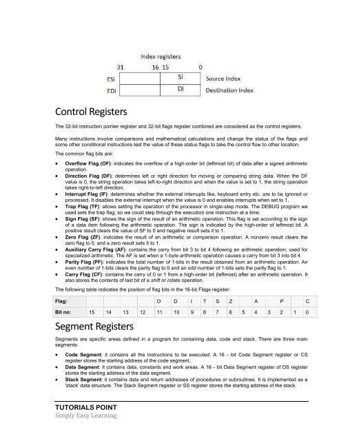
Control Registers<br />
The 32-bit instruction pointer register and 32-bit flags register combined are considered as the control registers.<br />
Many instructions involve comparisons and mathematical calculations and change the status of the flags and<br />
some other conditional instructions test the value of these status flags to take the control flow to other location.<br />
The common flag bits are:<br />
<br />
<br />
<br />
<br />
<br />
<br />
<br />
<br />
<br />
Overflow Flag (OF): indicates the overflow of a high-order bit (leftmost bit) of data after a signed arithmetic<br />
operation.<br />
Direction Flag (DF): determines left or right direction for moving or comparing string data. When the DF<br />
value is 0, the string operation takes left-to-right direction and when the value is set to 1, the string operation<br />
takes right-to-left direction.<br />
Interrupt Flag (IF): determines whether the external interrupts like, keyboard entry etc. are to be ignored or<br />
processed. It disables the external interrupt when the value is 0 and enables interrupts when set to 1.<br />
Trap Flag (TF): allows setting the operation of the processor in single-step mode. The DEBUG program we<br />
used sets the trap flag, so we could step through the execution one instruction at a time.<br />
Sign Flag (SF): shows the sign of the result of an arithmetic operation. This flag is set according to the sign<br />
of a data item following the arithmetic operation. The sign is indicated by the high-order of leftmost bit. A<br />
positive result clears the value of SF to 0 and negative result sets it to 1.<br />
Zero Flag (ZF): indicates the result of an arithmetic or comparison operation. A nonzero result clears the<br />
zero flag to 0, and a zero result sets it to 1.<br />
Auxiliary Carry Flag (AF): contains the carry from bit 3 to bit 4 following an arithmetic operation; used for<br />
specialized arithmetic. The AF is set when a 1-byte arithmetic operation causes a carry from bit 3 into bit 4.<br />
Parity Flag (PF): indicates the total number of 1-bits in the result obtained from an arithmetic operation. An<br />
even number of 1-bits clears the parity flag to 0 and an odd number of 1-bits sets the parity flag to 1.<br />
Carry Flag (CF): contains the carry of 0 or 1 from a high-order bit (leftmost) after an arithmetic operation. It<br />
also stores the contents of last bit of a shift or rotate operation.<br />
The following table indicates the position of flag bits in the 16-bit Flags register:<br />
Flag: O D I T S Z A P C<br />
Bit no: 15 14 13 12 11 10 9 8 7 6 5 4 3 2 1 0<br />
Segment Registers<br />
Segments are specific areas defined in a program for containing data, code and stack. There are three main<br />
segments:<br />
<br />
<br />
<br />
Code Segment: it contains all the instructions to be executed. A 16 - bit Code Segment register or CS<br />
register stores the starting address of the code segment.<br />
Data Segment: it contains data, constants and work areas. A 16 - bit Data Segment register of DS register<br />
stores the starting address of the data segment.<br />
Stack Segment: it contains data and return addresses of procedures or subroutines. It is implemented as a<br />
'stack' data structure. The Stack Segment register or SS register stores the starting address of the stack.<br />
TUTORIALS POINT<br />
Simply Easy Learning