Download Operating Instructions / Spare Parts List - HE-VA
Download Operating Instructions / Spare Parts List - HE-VA
Download Operating Instructions / Spare Parts List - HE-VA
Create successful ePaper yourself
Turn your PDF publications into a flip-book with our unique Google optimized e-Paper software.
Sub-Tiller 06-09-2011<br />
2
Sub-Tiller 06-09-2011<br />
Indhold<br />
EC DECLARATION OF CONFORMITY ................................................................................................... 4<br />
Delivery check .................................................................................................................................................. 5<br />
Machine Description ........................................................................................................................................ 5<br />
Range of Application ..................................................................................................................................... 5<br />
Technical specifications ................................................................................................................................. 5<br />
Safety instructions for Sub-Tiller ................................................................................................................... 6<br />
Safety and <strong>Instructions</strong> on Hydraulics ........................................................................................................... 7<br />
Labels on the machine ..................................................................................................................................... 8<br />
Start-up of the machine ................................................................................................................................... 9<br />
General information ....................................................................................................................................... 9<br />
Attachment and uncoupling (rigid machines) ................................................................................................ 9<br />
Attachment and uncoupling (hydr. machines) ............................................................................................... 9<br />
Settings and adjustment ................................................................................................................................ 10<br />
Stone protection ........................................................................................................................................... 10<br />
Replacement of wearing point ..................................................................................................................... 12<br />
Scraper ......................................................................................................................................................... 12<br />
Maintenance ................................................................................................................................................... 13<br />
Lubrication ................................................................................................................................................... 13<br />
<strong>Spare</strong> part list ................................................................................................................................................. 14<br />
Frame 2,5 – 4,0 m (rigid) ............................................................................................................................ 14<br />
Frame 4.0 – 5.0 m (hydraulic) ..................................................................................................................... 16<br />
Rollers .......................................................................................................................................................... 19<br />
Scraper ......................................................................................................................................................... 21<br />
Tine withQuick-Push shear boltt ................................................................................................................. 23<br />
Tine with hydraulic automatic release system ............................................................................................. 24<br />
Hydraulic marker ......................................................................................................................................... 26<br />
Light mounting............................................................................................................................................. 28<br />
Multi-Seeder mounting (rigid) ..................................................................................................................... 30<br />
Multi-Seeder mounting (hydraulic) ............................................................................................................. 32<br />
Fertilizer equipment (rigid) .......................................................................................................................... 34<br />
<strong>Spare</strong> part list – Hydraulics .......................................................................................................................... 36<br />
Support for accumulator .............................................................................................................................. 36<br />
Hydraulics for depth control of roller (rigid) ............................................................................................... 37<br />
Hydraulics for depth control of roller (hydraulic) ....................................................................................... 38<br />
Hydraulics for folding cylinder .................................................................................................................... 39<br />
Hydraulics for marker .................................................................................................................................. 40<br />
Hydraulics for automatic release system (rigid) .......................................................................................... 42<br />
Hydraulics for automatic release system (hydraulic)................................................................................... 44<br />
Notes ................................................................................................................................................................ 46<br />
3
Sub-Tiller 06-09-2011<br />
EC DECLARATION OF CONFORMITY<br />
in accordance with the EU Machinery Directive 2006/42/EC<br />
applicable as from December 29 th 2009:<br />
<strong>HE</strong>-<strong>VA</strong> ApS<br />
N. A. Christensensvej 34,<br />
DK-7900 Nykøbing Mors<br />
hereby confirms that the following machine has been manufactured in accordance with the Council<br />
Directive 2006/42/EC.<br />
The declaration comprises the following machine:<br />
Sub-Tiller 2.5m – 3.0m – 3.5m – 4.0m (rigid)<br />
Sub-Tiller 4.0m – 5.0m (hydraulic)<br />
Nykøbing 01.06.2010<br />
Villy Christiansen<br />
The undersigned is furthermore authorised to compile technical documentation for the above machine.<br />
4
Sub-Tiller 06-09-2011<br />
Delivery check<br />
Upon delivery to the dealer/supplier as well as to the customer, check the Sub-Tiller for possible damages.<br />
Range of Application<br />
Machine Description<br />
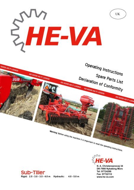
The Sub-Tiller is a sub-soiler for soil loosening from 0 cm to 60 cm depth. The work is preformed either<br />
before seeding (min. tillage) or after harvest where a loosening of the tramlines in the field is desirable in<br />
order to discourage structure damages. Infinitely variable tine spacing, depending on the actual working<br />
task. The Sub-Tiller is ideal for all soil types and a V-profile roller is recommendable for moist and sticky<br />
soil types while a square tube roller is recommendable for lighter soil types. The Sub-Tiller can be mounted<br />
with <strong>HE</strong>-<strong>VA</strong> Multi-Seeder which opens up the possibility of till-seeding of rape or crops for green manure.<br />
The Sub-Tiller is mounted in the tractor’s three-point suspension, and the hydraulic depth control via the<br />
packer roller is controlled by the hydraulic system of the tractor. In order to achieve optimum control you<br />
have to be aware of the tractor wheels, und under certain circumstances a mounting of twin wheels is<br />
recommendable.<br />
Technical specifications<br />
Rigid models<br />
Hydraulic models<br />
Model 2.5 m 3.0 m 3.5 m 4.0 m 4.0 m 5.0 m<br />
Working width 2.5 m 3.0 m 3.5 m 4.0 m 4.0 m 5.0 m<br />
Height folded 2.6 m 3.0 m<br />
Power requirement HP 60-200 60-200 140-280 200-280 200-280 200-360<br />
Requirement for number of double acting<br />
1 1 1 1 2 2<br />
oil outlets<br />
No. of tines 2-3pcs. 2-3-5pcs. 5-7 pcs. 7 pcs. 7 pcs. 7-9 pcs.<br />
Weight:<br />
Square tube roller and Quick-Push shear 985 kg 1230 kg 1480 kg 1560 kg 1910 kg 2240 kg<br />
bolt<br />
Square tube roller and hydraulic automatic 1090kg 1410 kg 1720 kg 1640 kg 1990 kg 2390 kg<br />
release system<br />
V-profile roller and Quick-Push shear bolt 1500kg 1850 kg 2200 kg 2380 kg 2730 kg 3260 kg<br />
V-profile roller and hydraulic automatic 1605kg 2025 kg 2440 kg 2620 kg 2970 kg 3690 kg<br />
release system<br />
Synchronous roller and Quick-Push shear 1205kg 1475 kg 1850 kg 1905 kg 2255 kg 2680 kg<br />
bolt<br />
Synchronous roller and hydr. automatic 1310kg 1650 kg 2090 kg 2145 kg 2495 kg 3110 kg<br />
release system<br />
Sub-Tiller complies with DS/ISO 11001-1, three-point suspension.<br />
5
Sub-Tiller 06-09-2011<br />
Safety instructions for Sub-Tiller<br />
Do not start-up the machine if there are persons in exposed positions* within a hazardous area**.<br />
When persons are in exposed positions (e.g. in connection with adjustment, maintenance, attachment and<br />
uncoupling), the following conditions must be observed:<br />
1. The machine must be lowered to firm ground.<br />
2. The hydraulics must be relieved.<br />
3. The tractor must be stopped and the key removed from the ignition switch.<br />
4. The driver must ensure that no persons are staying in exposed positions during the operation.<br />
* Person in exposed position: Any person who is staying wholly or partly within a hazardous area.<br />
** Hazardous area: On and under the machine within a distance of 4 m from the machine.<br />
Most accidents that happen in connection with the operation, transport and maintenance of machines are<br />
caused by non-compliance with the most elementary safety conditions.<br />
Therefore it is vital that anybody working at the machine carefully complies with the safety instructions as<br />
well as other instructions applying to the machine.<br />
The machine may only be operated, maintained and repaired by persons, who are familiar with this work<br />
and who are further familiar with the possible elements of danger with this particular machine.<br />
ATTENTION !!<br />
Rotary parts and loose clothes are a dangerous combination.<br />
IMPORTANT !!<br />
In connection with the risk of parts falling down, it may endanger the lives<br />
of persons staying on the base frame of the machine, when it is operated<br />
attached to a tractor.<br />
6
Sub-Tiller 06-09-2011<br />
Safety and <strong>Instructions</strong> on Hydraulics<br />
1. The maximum working pressure is 225 bar.<br />
2. It is advisable to label the attachment parts at hydraulic connections between the tractor and the tool<br />
in order to eliminate incorrect operation!<br />
3. When checking for hydraulic leaks, use suitable safety wear (eye protectors, gloves, etc.)<br />
High-pressure hydraulic oil may penetrate the skin and cause dangerous injuries.<br />
In case of injury, consult a doctor immediately. RISK OF INFECTION!<br />
4. Before operating the hydraulics, lower the machine to firm ground.<br />
Relieve the hydraulics, stop the motor and remove the ignition key.<br />
5. Check the hydraulic hoses on a regular basis, however, every six months as a minimum due to any<br />
cracks, wear and tear, etc. Replace any defective hoses immediately.<br />
The life of hydraulic hoses is maximum 5 years.<br />
New hydraulic hoses must meet the manufacturer's requirements.<br />
INSTRUCTIONS ON TRANSPORT ON T<strong>HE</strong> PUBLIC ROADS:<br />
Check before transport on public roads that the attachment of the machine at the tractor is in accordance<br />
with the local rules and regulations in force (permitted total weight, permitted axle load, transport width,<br />
lights, warning signs, etc.).<br />
FRONT AXLE LOAD:<br />
After the attachment of the machine and at maximum load, the driving properties of the tractor must be<br />
ensured. Check that the front axle is sufficiently loaded. As a minimum, the front axle load must be 20% of<br />
the tractor weight. Permitted axle load and permitted total weight for the tractor must always be observed.<br />
NB! The driving, controlling and braking properties are affected by the attached machine<br />
combination.<br />
7
Sub-Tiller 06-09-2011<br />
Labels on the machine<br />
You will find several labels on your machine containing safety and practical instructions as regards the<br />
correct application of the machine. Please study the instructions and point out to the user the importance of<br />
the labels as well as the safety instructions in the <strong>Operating</strong> <strong>Instructions</strong>. Always keep the labels clean and<br />
readable – if not they must be replaced.<br />
A<br />
B<br />
C<br />
D<br />
Explanation of the machine labels<br />
A<br />
B<br />
C<br />
D<br />
Plate with number and year of manufacture.<br />
Study the <strong>Operating</strong> <strong>Instructions</strong> thoroughly before any operation of the machine and observe<br />
all safety instructions.<br />
Tighten up all bolts regularly. If this is not performed, our guarantee obligations will no longer<br />
apply.<br />
Correct hydraulic pressure on the release system.<br />
8
Sub-Tiller 06-09-2011<br />
Start-up of the machine<br />
General information<br />
The machine requires 1 double acting outlet (rigid).<br />
The machine requires 2 double acting outlets (hydraulic).<br />
The hoses for depth adjustment are provided with red cable straps.<br />
Attachment and uncoupling (rigid machines)<br />
1. Under normal circumstances attach the tractor in the lowest lifting points of the machine both as<br />
regards the lifting arms and the top link.<br />
2. When the machine is to be parked and uncoupled from the tractor, it is important, that the roller is<br />
placed in the lowest position, so that the machine is placed stably.<br />
3. When uncoupling, relieve the tractor’s oil outlet, and the machine’s quick couplings can be<br />
uncoupled without pressure. The hydraulic cylinder which controls the roller is equipped with a<br />
pilot-controlled check valve which hermetically cuts off the oil for the hydraulic cylinder, meaning<br />
that it is locked in the chosen position regardless of the tightness of the quick couplings.<br />
Attachment and uncoupling (hydr. machines)<br />
1. Be aware that the machine is to be attached und uncoupled to the tractor in transport position.<br />
2. The roller has to be placed in the lowest position otherwise problems might occur during the folding.<br />
From transport to working position:<br />
3. The machine is to be raised to max. transport height.<br />
4. The depth adjusting cylinder is placed at the top.<br />
5. Now unfold the wing sections.<br />
6. Adjust the working depth.<br />
From working to transport position:<br />
7. Raise the machine to max. transport height.<br />
8. The depth adjusting cylinder (the roller) is placed at the top.<br />
9. Now the wing sections are folded together into transport position. Be sure that the locking claws<br />
lock the wing sections.<br />
9
Sub-Tiller 06-09-2011<br />
Settings and adjustment<br />
Stone protection<br />
Quick-Push shear bolt.<br />
When the shear bolt is broken and the tine has been released, place the shear bolt one notch forward before<br />
the machine can operate again.<br />
1 Pull out the R-clip (Pos. 1).<br />
2 Pull the tine back to normal working position (Pos. 2).<br />
3 Push the shear bolt (Pos. 3) one notch forward to a<br />
new position in the tine. Do not push the bolt totally<br />
through (it can be necessary to remove soil etc. from<br />
the hole in the tine).<br />
Important: All activities under the machine are<br />
deprecated when the shear bolt is being moved or<br />
changed.<br />
4 Push back the R-clip (Pos. 1), so that it locks the<br />
shear bolt in its place, and the machine is ready for<br />
operation.<br />
When the shear bolt is broken for the eighth time, it is used up. Be aware that the shear bolt must never be<br />
shorter than 65 mm.<br />
When a new shear bolt is mounted it is important that it is placed rightly. The end of 40 mm (Pos. 3) is to<br />
turn away from the tine.<br />
10
Sub-Tiller 06-09-2011<br />
Hydraulic automatic release system.<br />
1<br />
1 Before each season it has to be controlled, that the gas pressure<br />
in the accumulator (Pos.1) is 90 bars. This requires special<br />
tools and can only be preformed by an authorized dealer.<br />
2<br />
3 4<br />
2 Before the start-up of the machine the hydraulic pressure in the<br />
closed hydraulic stone protection system has to be controlled<br />
on the machine’s pressure gauge (Pos. 2). The pressure has to<br />
be minimum 100 bar and must not exceed 160 bar.<br />
3 IMPORTANT – the hydraulic pressure is to be controlled<br />
continuously and must never be under 100 bar.<br />
4 If there is a need to adjust the working pressure, follow the<br />
below instructions:<br />
a<br />
b<br />
c<br />
Mount the quick coupling of the hydraulic hose (Pos. 3) in<br />
the tractor’s oil outlet.<br />
Turn on the ball valve (Pos. 4), and the working pressure<br />
can now be adjusted up or down with the tractor’s oil<br />
outlet.<br />
When the desired pressure is achieved, turn off the ball<br />
valve again (Pos. 4), and the tractor’s hydraulic system is<br />
relieved before the quick coupling (Pos. 3) is dismounted<br />
and placed in the parking device of the machine.<br />
5 During the operation of the machine the tine is swinging<br />
automatically to the rear if it meets an obstacle. In normal<br />
circumstances the tine will automatically return to the working<br />
position again after having passed the obstacle. At extreme<br />
obstacles and/or soil conditions it might be necessary to stop<br />
and eventually lift the machine from the soil. It is<br />
important that no persons are near to the machine as the tine is<br />
returning to the working position with high speed and might<br />
throw with soil and stones.<br />
11
Sub-Tiller 06-09-2011<br />
Replacement of wearing point<br />
1<br />
2<br />
1. Before working with the machine’s wearing points, the<br />
machine is to be fastened. This can be performed by trestles<br />
under the main frame or by a support of the roller.<br />
2. Dismount M16x65 mm bolt (Pos. 1) by means of 2 pcs. 24<br />
mm spanners. The wearing point might fall off, when the<br />
bolt is removed – take care of foot and leg injuries.<br />
3. Dismount the wearing point by pushing it forward. This<br />
might be difficult due to entrance of soil, and it might be a<br />
good idea to use a hammer.<br />
4. Mount the new wearing point, item no. 645000044 (Pos. 2),<br />
by pushing the wearing point to the rear and then in its<br />
place.<br />
5. Check the M16 x 65 mm bolt for eventual damages and<br />
replace it as required, item no. 690103190 + 690113008.<br />
6. Mount the M16 x 65 mm bolt (Pos. 1), lubricate and tighten<br />
it with 25 Nm.<br />
Scraper<br />
The Sub-Tiller has special designed scrapers<br />
among the packer rings on the V-profile roller.<br />
To avoid unnecessary wear and to obtain the best<br />
scraper effect it is important to check the centering<br />
of the scrapers every day<br />
12
Sub-Tiller 06-09-2011<br />
Maintenance<br />
<br />
<br />
<br />
After 10 hours of operation, retighten the machine. Check hydraulic hoses, fittings and cylinders for<br />
leaks and retighten.<br />
Further check on a regular basis that all bolts are tightened.<br />
Before the winter storage, wash and lubricate the machine. If you use high-pressure cleaner, do not<br />
spray directly on the ball bearings. After the washing, you may spray the machine with oil.<br />
Lubrication<br />
For lubrication, maintenance and repair, lower the Sub-Tiller, put the brakes of the tractor on and stop the<br />
motor.<br />
The 2.5 – 4.0 m Sub-Tiller (rigid) have five lubricating points and the 4.0 – 5.0 m Sub-Tiller (hydraulic)<br />
have 20 lubricating points - all Sub-Tillers must be lubricated after every 30 working hours as well as after<br />
the cleaning in order to press out any water and dirt. The lubricating points on the rigid machines are located<br />
where the bar is mounted on the frame as well as at ball bearings and cylinders. The lubrication points on the<br />
hydraulic machines are furthermore located where the wing sections are hinged on the middle section and at<br />
the locking mechanism of the wing sections on the middle section.<br />
X<br />
Lubricating point<br />
Moreover, the machines with hydraulic automatic release system have 2 lubricating points per tine which are<br />
to be lubricated after 10 hours of operation.<br />
Attention!<br />
However, the double-sealed ball bearings in the roller<br />
should only by lubricated every 20 working hours and by<br />
1-2 strokes so that the sealing rings are not pressed out.<br />
Important!<br />
Oil, type Hydro Texaco HD32 has<br />
been filled in the hydraulic system.<br />
13
Sub-Tiller 06-09-2011<br />
<strong>Spare</strong> part list<br />
Frame 2,5 – 4,0 m (rigid)<br />
Pos. Item no. Designation 2,5 m 3,0 m 3,5 m 4,0 m<br />
1 645000149 Frame 2.5 m 1<br />
1 645000002 Frame 3.0 m 1<br />
1 645000090 Frame 3.5 m 1<br />
1 645000138 Frame 4.0 m 1<br />
2 69537105C Pin for lift arm Ø37/Ø50 L=105 2 2 2 2<br />
3 69532105C Pin for top link Ø32/Ø45 L=105 1 1 1 1<br />
14
Sub-Tiller 06-09-2011<br />
Pos. Item no. Designation 2,5 m 3,0 m 3,5 m 4,0 m<br />
4 645000153 Roller bar 2.5 m 1<br />
4 645000027 Roller bar 3.0 m 1<br />
4 645000156 Roller bar 3.5 m 1<br />
4 645000157 Roller bar 4.0 m 1<br />
5 69430145G Pin Ø30 L=145 2 2 2 2<br />
6 0235330 Steel setscrew M12x25 8.8 4 4 4 4<br />
7 690134008 Ring pin Ø11,5 2 2 2 2<br />
8 630532600 Lock bush for pin head 4 4 4 4<br />
9 0432500 Lubricating nipple M8 3 3 3 3<br />
10 645000036 Cylinder for depth adjustment 1 1 1 1<br />
11 69430200G Pin Ø30 L=200 1 1 1 1<br />
12 69430125G Pin Ø30 L=125 1 1 1 1<br />
13 645000162 Scale for depth control 1 1 1 1<br />
14 0272260 Facet plate Ø10 4 4 4 4<br />
15 0235070 Steel setscrew M10x40 8.8 2 2 2 2<br />
16 0264060 Self-locking nut M10 2 2 2 2<br />
17 645000165 Pointer for depth control 1 1 1 1<br />
18 0382160 U-bolt M16 100x100x100 1 1 1 1<br />
19 0272290 Facet plate Ø16 2 2 2 2<br />
20 0264090 Self-locking nut M16 2 2 2 2<br />
21 645000404 Transport bracket 1 1 1 1<br />
22 0236160 Steel bolt M20x75 8.8 2 2 2 2<br />
15
Sub-Tiller 06-09-2011<br />
Frame 4.0 – 5.0 m (hydraulic)<br />
16
Sub-Tiller 06-09-2011<br />
Pos. Item no. Designation Number<br />
1 645000197 Middle frame 1<br />
645000415 Middle frame (from machine number:26691) 1<br />
2 645000201 4 m wing, left 1<br />
645000200 4 m wing, right 1<br />
645000250 5 m wing, left 1<br />
645000249 5 m wing, right 1<br />
3 645000242 4 m roller bar, left 1<br />
645000241 4 m roller bar, right 1<br />
645000258 5 m roller bar, left 1<br />
645000257 5 m roller bar, right 1<br />
4 630532600 Lock bush for pin head 16<br />
5 0235330 Steel setscrew M12x25 8.8 16<br />
6 69440367G Pin Ø40x367 4<br />
7 690200255 Cylinder 90/40x500 2<br />
8 0272528 Shim Ø62x42x1 10<br />
9 0272530 Shim Ø62x42x2 10<br />
10 0235840 Steel bolt M16x60 8.8 8<br />
11 645000397 Shim<br />
12 645000382 Shim<br />
13 0264090 Self-locking nut M16 8<br />
14 0432500 Lubricating nipple M8 8<br />
15 69440110G Pin Ø40x110 2<br />
16 0382160 U-bolt M16 100x100x100 1<br />
17 645000165 Pointer for depth control 1<br />
18 645000162 Scale for depth control 1<br />
19 0272290 Facet plate Ø16 5<br />
20 0235070 Steel setscrew M10x70 8.8 2<br />
21 0272260 Facet plate Ø10 4<br />
22 0264060 Self-locking nut M10 2<br />
23 645000404 Transport bracket 1<br />
24 0236160 Steel bolt M20x75 8.8 2<br />
25 69430145G Pin Ø30x145 2<br />
26 690200117 Cylinder 80/40x255 2<br />
27 0432100 Lubricating nipple M8 2<br />
28 0261452 Counter nut M30x2 2<br />
29 690140772 Rod end M30x2 (male thread) 2<br />
30 69430090G Pin Ø30x90 2<br />
31 69440165G Pin Ø40x165 2<br />
32 69537125C Pin for lift arm Ø37/Ø50x328 2<br />
33 69532095C Pin for top link Ø32/Ø44x95 1<br />
34 690134008 Ring pin Ø11,5 3<br />
35 645000273 Support stand 4<br />
36 69516094A Pin Ø16x94 4<br />
37 0377400 R-clip Ø4 4<br />
38 645000169 Locking claw, left 1<br />
39 645000170 Locking claw, right 1<br />
17
Sub-Tiller 06-09-2011<br />
Pos. Item no. Designation Number<br />
40 690200170 Cylinder 40/25x80 1<br />
41 0235880 Steel bolt M16x80 8.8 1<br />
42 0235830 Steel bolt M16x55 8.8 1<br />
43 0371690 Roll pin Ø8x40 2<br />
44 0272340 Facet plate Ø27 4<br />
45 690200664 Distance clip blue 6.2mm 2<br />
690200665 Distance clip red 9.4mm 2<br />
690200666 Distance clip yellow 18.8mm 2<br />
690200667 Distance clip black 31.6mm 4<br />
690200668 Distance clip silver 50.8mm 4<br />
46 690134036 Bush for lift arm Ø37.5 4<br />
47 690134038 Bush for lift arm Ø50.5 4<br />
48 690134034 Bush for top link Ø32.5 3<br />
49 690134037 Bush for top link Ø45.5 3<br />
18
Sub-Tiller 06-09-2011<br />
Rollers<br />
Pos. Item no. Designation Number<br />
1 0395270 Wheel bolt M14x1,5x35mm. 10-45<br />
2 0395600 Complete wheel 200/60-14,5 2-9<br />
3 645000436 Hub 2-9<br />
4 0395290 Wheel nut M14x1,5 10-45<br />
5 0272550 Shim Ø78,5x2mm<br />
6 0272560 Shim Ø78,5x5mm<br />
7 645000410 Shim Ø82,5x8mm<br />
8 645000412 Shim Ø82,5x16 for M8 pivot screw<br />
9 645000439 Shim Ø82,5x15 for M12 steel setscrew<br />
10 645000411 Shim Ø82,5x20 for M10 steel setscrew<br />
19
Sub-Tiller 06-09-2011<br />
Pos. Item no. Designation Number<br />
11 645000442 Shim Ø82,5x15mm<br />
12 645000441 Shim Ø82,5x20mm<br />
13 645000432 Shim Ø82,5x23mm<br />
14 645000433 Shim Ø82,5x28mm<br />
15 645000434 Shim Ø82,5x31mm<br />
16 645000435 Shim Ø82,5x35mm<br />
17 645000430 Shim Ø82,5x92mm<br />
18 645000440 Shim Ø82,5x105mm<br />
19 0227521 Stopscrew M8x20mm<br />
20 0235330 Steel setscrew M12x25mm<br />
21 0235040 Steel setscrew M10x25mm<br />
22 1069111 T-profile ring with spoke<br />
23 1048100 Double T-profile ring, narrow + wide<br />
24 1048110 Double T-profile ring, wide + wide<br />
25 645000438 T-profile ring with 124mm hub<br />
26 645000431 T-profile ring with 92mm hub<br />
27 645000406 T-profile ring with 40mm hub<br />
28 678612435 2.5m rigid & 5.0m hydraulic, axle 2435mm 1-2<br />
678612935 3.0m rigid, axle 2935mm 1<br />
678613435 3.5m rigid, axle 3435mm 1<br />
678613935 4.0m rigid, axle 3935mm 1<br />
678611935 4.0m hydraulic, axle 1935mm 1<br />
29 691370150 Seeger circlip ring Ø150 DIN 471<br />
30 630764006 Console for support bearing<br />
31 630764008 Bearing housing<br />
32 690140115 Ball bearing, Ø60 UC 312<br />
33 690110105 U-bolt M16x100x200<br />
34 0272290 Facet plate M16<br />
35 0264090 Self-locking nut M16<br />
36 1048210 2.5m rigid & 5.0m hydraulic, square tube roller Ø550 1-2<br />
1048240 3.0m rigid, square tube roller Ø550 1<br />
1048280 3.5m rigid, square tube roller Ø550 1<br />
1048330 4.0m rigid, square tube roller Ø550 1<br />
1048310 2.0m hydraulic, square tube roller Ø550 2<br />
37 690140808 Bearing complete Ø60 UCF 312 2-4<br />
38 0236140 Steel bolt M20x65mm. 8-16<br />
39 0272310 Facet plate M20 8-16<br />
40 0264110 Self-locking nut M20 8-16<br />
41 630936300 2.5m rigid & 5.0m, V-profile roller Ø600 1-2<br />
630916300 3.0m rigid, V-profile roller Ø600 1<br />
630916350 3.5m rigid, V-profile roller Ø600 1<br />
630926300 4.0m rigid, V-profile roller Ø600 1<br />
630926301 4.0m hydraulic, V-profile roller Ø600 1<br />
20
Sub-Tiller 06-09-2011<br />
Scraper<br />
Rigid<br />
Hydr.<br />
Pos. Item no. Designation 2,5m 3,0m 3,5m 4,0m 4,0m 5,0m<br />
1 645000287 Scraper bar 1<br />
1 630918555 Scraper bar 1<br />
1 630918150 Scraper bar 1<br />
1 630928555 Scraper bar (right) 1 1<br />
1 630938555 Scraper bar (right) 1<br />
1 630928565 Scraper bar (left) 1 1<br />
1 630938565 Scraper bar (left) 1<br />
21
Sub-Tiller 06-09-2011<br />
Pos. Item no. Designation 2,5m 3,0m 3,5m 4,0m 4,0m 5,0m<br />
2 690110106 U-bolt M16x200x100x200 4 4 4 8 8 8<br />
3 0272290 Facet plate Ø16 8 8 8 16 16 16<br />
4 0264090 Self-locking nut M16 8 8 8 16 16 16<br />
5 690110025 U-bolt M10x50x70x50 19 23 27 31 31 39<br />
6 630938506 Scraper double 9 11 13 15 15 19<br />
7 630938505 Scraper single 1 1 1 1 1 1<br />
8 630938507 Clamping plate 19 23 27 31 31 39<br />
9 0272260 Facet plate Ø10 38 46 54 62 62 78<br />
10 0264060 Self-locking nut M10 38 46 54 62 62 78<br />
11 645000469 Scraper bar f/synchronous roller 1<br />
645000467 Scraper bar f/synchronous roller 1<br />
645000471 Scraper bar f/synchronous roller 1<br />
645000473 Scraper bar f/synchronous roller 1<br />
645000475 Scraper bar f/synchronous roller 1<br />
12 630938523 Scraper tine – long model 17<br />
13 630938524 Scraper tine – short model 1<br />
14 630938522 Clamp 50x70 f/scraper 18<br />
15 0235450 Steel bot M12x90mm. 18<br />
16 0272270 Facet plate Ø12 18<br />
17 0264070 Self-locking nut M12 18<br />
22
Sub-Tiller 06-09-2011<br />
Tine withQuick-Push shear boltt<br />
Pos. Item no. Designation Number per leg<br />
1 645000062 Tine for Quick-Push 1<br />
2 645000044 Wearing point 1<br />
3 0235850 Steel bolt M16x65 8.8 1<br />
4 0272290 Facet plate Ø16 2<br />
5 0264090 Self-locking nut M16 9<br />
6 645000328 Clamping plate for tine bracket 1<br />
7 645000055 Tine bracket (left) 1<br />
7 645000051 Tine bracket (right + centre) 1<br />
8 690117060 Facet plate Ø16 (hardened) 16<br />
9 0238850 Steel bolt M16x90 10,9 8<br />
10 645000059 Shear bolt Ø34 1<br />
11 69435070F Pin Ø35 L=71 1<br />
12 690134004 Ring pin Ø10 1<br />
13 0377600 R-clip 6 mm electroplated 1<br />
14 0227523 Pivot screw M12x20 DIN916 2<br />
23
Sub-Tiller 06-09-2011<br />
Tine with hydraulic automatic release system<br />
24
Sub-Tiller 06-09-2011<br />
Pos. Item no. Designation No. per leg<br />
1 645000124 Tine bracket for hydr. automatic release system (left) 1<br />
1 645000072 Tine bracket for hydr. automatic release system (r + c) 1<br />
2 645000086 Tine for hydraulic automatic release system 1<br />
3 645000044 Wearing point 1<br />
4 0235850 Bolt M16x65 8.8 1<br />
5 0272290 Facet plate Ø16 2<br />
6 0264090 Self-locking nut M16 9<br />
7 0238850 Bolt M16x90 10,9 8<br />
8 690117060 Facet plate Ø16 (hardened) 16<br />
9 645000328 Clamping plate for tine bracket 1<br />
10 0227523 Pivot screw M12x20 DIN916 2<br />
11 690200305 Cylinder 110/50x165 with yoke (until masnr. 27671) 1<br />
11 0467400 Cylinder 110/50x165 with yoke (from masnr. 27710)<br />
11a 690200313 Gasket set for cylinder 1<br />
12 0432500 Lubricating nipple M8 2<br />
13 690103868 Steel bolt M30x95 10.9 (until masnr. 27671) 1<br />
13 645000500 Pin (from masnr. 27710)<br />
14 0272350 Facet plate Ø30 (until masnr. 27671) 2<br />
15 645000113 Bush for hydraulic tine (until masnr. 27671) 1<br />
16 0264155 Self-locking nut M30 (until masnr. 27671) 1<br />
16 0264190 Self-locking nut M36 (from masnr. 27710)<br />
17 69440165G Pin Ø40 L=165 1<br />
18 69440195G Pin Ø40 L=195 1<br />
19 630532600 Lock bush for pin head 2<br />
20 0235330 Steel setscrew M12x25 8,8 2<br />
21 690140715 Slide bush Ø40/40x40 2<br />
25
Sub-Tiller 06-09-2011<br />
Hydraulic marker<br />
Pos. Item no. Designation Number<br />
1 645000320 Marker bearing, left 1<br />
645000321 Marker bearing, right 1<br />
2 0235840 Steel bolt M16x60 8.8 8<br />
3 0272290 Facet plate Ø16 34<br />
4 0264090 Self-locking nut M16 34<br />
5 0235330 Steel setscrew M12x25 8.8 2<br />
6 630532600 Lock bush for pin head 2<br />
7 69430275G Pin Ø30x275 2<br />
26
Sub-Tiller 06-09-2011<br />
Pos. Item no. Designation Number<br />
8 1140043 Turning link, left 1<br />
1140044 Turning link, right 1<br />
9 0432500 Lubricating nipple M8 4<br />
10 0236090 Steel setscrew M20x40 8.8 2<br />
11 0261410 Steel nut M20 2<br />
12 0236210 Steel bolt M20x120 8.8 2<br />
13 0272310 Facet plate Ø20 4<br />
14 1140091 Distance bush 2<br />
15 0264110 Self-locking nut M20 2<br />
16 0235450 Steel bolt M12x90 8.8 2<br />
17 1140358 Bush 4<br />
18 1140094 Bush 2<br />
19 0264070 Self-locking nut M12 6<br />
20 690200153 Cylinder 50/30x300 2<br />
21 0236010 Steel bolt M16x220 8.8 8<br />
22 645000308 Clamping plate 2<br />
23 645000309 Cylinder bearing, left 1<br />
645000316 Cylinder bearing, right 1<br />
24 0373350 Split pin Ø5x50 2<br />
25 0271650 Washer Ø24 2<br />
26 645000322 Marker outer tube, left 1<br />
645000323 Marker outer tube, right 1<br />
27 690304500 Shackle 10 mm 2<br />
28 0433490 Stay tightener M16 2<br />
29 0431800 Extension spring 2<br />
30 0235380 Steel bolt M12x50 8.8 2<br />
31 0272270 Facet plate Ø12 8<br />
32 0261100 Steel nut M12 2<br />
33 0235790 Steel setscrew M16x40 8.8 2<br />
34 645000315 Marker inner tube, left 1<br />
645000314 Marker inner tube, right 1<br />
35 1140127 Bracket plate, left 1<br />
1140128 Bracket plate, right 1<br />
36 0248670 Bolt (carrier bolt) M12x45 4<br />
37 0379220 Seeger circlip ring I 62 2<br />
38 0483401 Sealing lamella Z 206 2<br />
39 0472960 Ball bearing 6305 Z 4<br />
40 1066840 Distance bush 2<br />
41 0489380 Plastic plug 2<br />
42 1066810 Hub 2<br />
43 0428051 Disc Ø510 2<br />
44 0248421 Bolt (carrier bolt) M10x30 12<br />
45 0264060 Self-locking nut M10 12<br />
27
Sub-Tiller 06-09-2011<br />
Light mounting<br />
28
Sub-Tiller 06-09-2011<br />
Pos. Item no. Designation Number<br />
1 1043480 Bracket for light, left 1<br />
1043510 Bracket for light, right 1<br />
2 0527040 Marking lights 2<br />
3 0656240 Reflex, yellow 2<br />
4 0243000 Machine screw M6x20 4<br />
5 0272240 Facet plate Ø6 16<br />
6 0264040 Self-locking nut M6 16<br />
7 0656260 Reflex, red 2<br />
8 0656250 Reflex, white 2<br />
9 0527000 Rear light, left 1<br />
0527010 Rear light, right 1<br />
10 30930110 Bracket 2<br />
11 30910110 Bracket 2<br />
12 0234330 Steel setscrew M6x20 6<br />
13 0230825 Screw Tapetite M8x25 4<br />
29
Sub-Tiller 06-09-2011<br />
Multi-Seeder mounting (rigid)<br />
Pos. Item no. Designation Number<br />
1 645000332 Bracket for hydr. fan 1<br />
2 0264090 Self-locking nut M16 16<br />
3 0272290 Facet plate Ø16 18<br />
4 645000065 Seed hopper plate for 200 l 1<br />
5 645000331 Seed hopper plate for 410 l 1<br />
6 0382800 U-bolt M16x100x150x100 2<br />
7 0272260 Facet plate Ø10 8<br />
8 0264060 Self-locking nut M10 4<br />
9 0539102 2.5 – 3.0 m flexible driving cable 3.50 m 1<br />
0539117 3.5 – 4.0 m. flexible driving cable 3.75 m 1<br />
10 690110106 U-bolt M16x200x100x200 5<br />
11 645000099 Suspension for driving wheel 1<br />
12 0236210 Steel bolt M20x120 8.8 1<br />
13 0272310 Facet plate Ø20 2<br />
14 0264110 Self-locking nut M20 1<br />
30
Sub-Tiller 06-09-2011<br />
Pos. Item no. Designation Number<br />
15 69516094A Pin for support stand Ø16 L=94 mm 1<br />
16 0377400 R-clip Ø4 1<br />
17 0235910 Steel bolt M16x110 8.8 2<br />
18 645000111 Pivoting arm for driving wheel 1<br />
19 645000109 Flange for suspension for driving wheel 1<br />
20 645000335 Tube bracket 1<br />
21 645000275 C-profile for mounting of seed tube outlet 2.5 m 1<br />
645000276 C-profile for mounting of seed tube outlet 3 m 1<br />
645000277 C-profile for mounting of seed tube outlet for 3.5 m 1<br />
645000278 C-profile for mounting of seed tube outlet for 4 m 1<br />
22 645000260 Bracket for mounting of C-profile 3<br />
23 645000291 Seed hose bracket 1<br />
24 0382120 U-bolt M12 40x40x40 3<br />
25 0272270 Facet plate Ø12 6<br />
26 0264070 Self-locking nut M12 6<br />
27 0539055 Seed hose Ø26 inside 2-9<br />
28 690109306 Clamp 26-38 mm 12 mm wide 2-9<br />
29 645000285 Seed tube outlet for Sub-Tiller, bended 2-9<br />
30 0449705 Tube-support Ø25, single 2-9<br />
31 690210224 Welding plate for tube-support Ø25, single 2-9<br />
32 0449706 Top plate for tube-support Ø25, single 2-9<br />
33 0234390 Steel bolt M6x50 8.8 6-14<br />
34 0234400 Steel bolt M6x60 8.8 4<br />
35 645000286 Bracket for seed tube outlet 2<br />
36 0272240 Facet plate Ø6 12<br />
37 0264040 Self-locking nut M6 4<br />
38 1139500 Cable bracket, mounted on the roller frame 1<br />
39 0235460 Steel bolt M12x100 8.8 1<br />
40 645000337 Cable bracket 1<br />
41 645000380 Cable bracket, mounted on the main frame 1<br />
42 645000372 Cable bracket 1<br />
43 645000420 Extension for hose bracket 1<br />
44 0235830 Steel bolt M16x55 8.8 2<br />
Attention:<br />
The number of hoses and hose lengths can vary - dependent on the machine type, therefore check<br />
measurements and number before ordering the spare parts.<br />
Multi-Seeder<br />
If the Sub-Tiller is mounted with <strong>HE</strong>-<strong>VA</strong> Multi-Seeder, we refer you to the separate Multi-Seeder Manual<br />
with spare part list.<br />
31
Sub-Tiller 06-09-2011<br />
Multi-Seeder mounting (hydraulic)<br />
32
Sub-Tiller 06-09-2011<br />
Pos. Item no. Designation Number<br />
1 645000360 Light bar 1<br />
2 645000245 Bar 1<br />
645000364 Bracket for light bar without seed equipment 1<br />
3 645000261 Seed hopper plate 410 l 1<br />
4 0235950 Steel bolt M16x150 8.8 2<br />
5 0272290 Facet plate Ø16 40<br />
6 0264090 Self-locking nut M16 32<br />
7 0382160 U-bolt M16 100x100x100 1<br />
8 0235860 Steel bolt M16x70 8.8 6<br />
9 0539117 Flexible driving cable 3.75 m 1<br />
10 645000419 C-profile for mounting of seed tube outlet 4 m 2<br />
645000275 C-profile for mounting of seed tube outlet 5 m 2<br />
11 645000260 Bracket for mounting of C-profile 4<br />
12 690110106 U-bolt M16x200x100x200 5<br />
13 645000291 Seed hose bracket 1<br />
14 0382120 U-bolt M12 40x40x40 4<br />
15 0539055 Seed hose Ø26 inside 7-9<br />
16 690109306 Clamp 26-38 mm 12 mm wide 7-9<br />
17 645000285 Seed tube outlet for Sub-Tiller, bended 7-9<br />
18 0449705 Tube-support Ø25, single 14-18<br />
19 690210224 Welding plate for tupe support Ø25, single 7-9<br />
20 0449706 Top plate for tube-support Ø25, single 7-9<br />
21 0234390 Steel bolt M6x50 8.8 14-18<br />
22 0234400 Steel bolt M6x60 8.8 4<br />
23 645000286 Bracket for seed tube outlet 2<br />
24 0272240 Facet plate Ø6 4<br />
25 0264040 Self-locking nut M6 4<br />
26 645000337 Cable bracket 1<br />
27 645000380 Cable bracket, mounted on the main frame 1<br />
28 645000372 Cable bracket 1<br />
29 1139500 Cable bracket, mounted on the roller frame 1<br />
30 0235460 Steel bolt M12x100 8.8 1<br />
31 645000335 Tube bracket 1<br />
32 645000099 Suspension for driving wheel 1<br />
33 0236210 Steel bolt M20x120 8.8 1<br />
34 0272310 Facet plate Ø20 2<br />
35 0264110 Self-locking nut M20 1<br />
36 69516094A Hub for support stand Ø16 L=94 mm 1<br />
37 0377400 R-clip Ø4 1<br />
38 0235910 Steel bolt M16x110 8.8 2<br />
39 645000111 Pivoting arm for driving wheel 1<br />
40 645000109 Flange for suspension for driving wheel 1<br />
33
Sub-Tiller 06-09-2011<br />
Fertilizer equipment (rigid)<br />
34
Sub-Tiller 06-09-2011<br />
Pos. Item no. Designation Per tine Fertilizer<br />
Universal<br />
spreader<br />
1 0235460 Steel bolt M12x100 8.8 1<br />
2 1139500 Cable bracket 1<br />
3 0235370 Steel bolt M12x45 8.8 2<br />
4 0272270 Facet plate Ø12 8<br />
5 645000403 Cable bracket 1<br />
6 0264070 Self-locking nut M12 4<br />
7 0234400 Steel bolt M6x60 8.8 2<br />
8 0272240 Facet plate Ø6 4<br />
9 0449706 Top plate for tube-support Ø25, single 2<br />
10 645000344 Bracket for fertilizer tube 1<br />
11 0449705 Tube-support Ø25, single 2<br />
12 0264040 Self-locking nut M6 4<br />
13 0234350 Steel bolt M6x30 8.8 2<br />
14 0271530 Washer Ø6 4<br />
15 0487487 Rubber hose ø25x350 1<br />
16 645000283 Seed tube outlet, bended 1<br />
17 0434460 Clamp 26-38 mm 9 mm wide 1<br />
18 0539055 Seed hose Ø26 inside 1<br />
19 645000345 Bracket for fertilizer tank 410 l 1<br />
20 0235060 Steel setscrew M10x35 2<br />
21 0272260 Facet plate Ø10 4<br />
22 0264060 Self-locking nut M10 2<br />
23 0382850 U-bolt M16 260x180x260 2<br />
24 0272290 Facet plate Ø16 8 4<br />
25 0264090 Self-locking nut M16 8 4<br />
26 645000377 Stand for Universal spreader 1<br />
27 0235440 Steel bolt M12x80 8.8 2<br />
28 690110106 U-bolt M16 200x100x200 2<br />
29 0235140 Steel setscrew M10x75 1<br />
30 645000429 Cable bracket 1<br />
35
Sub-Tiller 06-09-2011<br />
<strong>Spare</strong> part list – Hydraulics<br />
Support for accumulator<br />
Pos. Item no. Designation Rigid Hydraulic<br />
1 645000370 Support for accumulator 1<br />
1 645000422 Support for accumulator (from machine no. 26691) 1<br />
2 645000125 Support for accumulator (rigid models) 1<br />
3 690206516 Clamp 175-187 mm. 2 2<br />
4 690206513 Accumulator 4,5L 90 bar 2 2<br />
5 0235370 Steel bolt M12x45 8.8 3<br />
6 0272270 Facet plate Ø12 6<br />
7 0264070 Self-locking nut M12 3<br />
8 0382800 U-bolt M16x100x150x100 2<br />
9 0272290 Facet plate Ø16 4<br />
10 0264090 Self-locking nut M12 4<br />
36
Sub-Tiller 06-09-2011<br />
Hydraulics for depth control of roller (rigid)<br />
Pos. Item no. Designation 2,5m 3,0m 3,5m 4,0m<br />
1 0444020 Quick coupling, male E402 ½” 2 2 2 2<br />
2 0449070 Bounded seal ½” 2 2 2 2<br />
3 0446752 Fitting, straight Ø10-½” BSP 2 2 2 2<br />
4 690201046 Hydraulic hose 1660 mm ¼” 2<br />
690201016 Hydraulic hose 1830 mm ¼” 2<br />
0454577 Hydraulic hose 1950 mm ¼” 2<br />
0454645 Hydraulic hose 2300 mm ¼” 2<br />
5 0446678 Fitting 90angle Ø10x⅜” 2 2 2 2<br />
6 0446751 Hexagon nipple Ø10x⅜” 2 2 2 2<br />
7 0449060 Bounded seal ⅜” 4 4 4 4<br />
8 662000804 Hydraulic tube Ø12 L=106 2 2 2 2<br />
9 690203111 Union nut Ø12 4 4 4 4<br />
10 690203110 Olive ring Ø12 4 4 4 4<br />
11 0446679 Fitting 90angle Ø12 2 2 2 2<br />
12 0446754 Hexagon nipple Ø12x⅜” 2 2 2 2<br />
13 645000036 Cylinder 80/40 – 280 mm. 1 1 1 1<br />
13A 690200142 Gasket set 80/40 1 1 1 1<br />
14 0442510 Check valve (pilot-controlled, double) ⅜” 1 1 1 1<br />
37
Sub-Tiller 06-09-2011<br />
Hydraulics for depth control of roller (hydraulic)<br />
Right<br />
Left<br />
Pos. Item no. Designation Number<br />
1 0444020 Quick coupling, male E402 ½” 2<br />
2 0446752 Fitting, straight Ø10-½” BSP 2<br />
3 0454645 4 m hydr. hose 2300 mm. ¼” st/st 4<br />
3 0454645 5 m hydr. hose 2300 mm. ¼” st/st 4<br />
4 690203015 Fitting T Ø10 2<br />
5 0454583 4 m hydr. hose 2050 mm. ¼” st/st 2<br />
5 0454583 5 m hydr. hose 2050 mm. ¼” st/st 2<br />
6 690203006 Fitting, 90angle Ø10-⅜” BSP 4<br />
7 690200085 Cylinder 80/40 – 255 mm. 2<br />
38
Sub-Tiller 06-09-2011<br />
Hydraulics for folding cylinder<br />
Right<br />
Left<br />
Pos. Item no. Designation Number<br />
1 0444020 Quick coupling, male E402 ½” 2<br />
2 0446752 Fitting, straight Ø10-½” BSP 4<br />
3 0454938 Hydraulic hose 3700 mm. ¼” st/st 1<br />
4 0454577 Hydraulic hose 1950 mm. ¼” st/st 1<br />
5 0454498 Hydraulic hose 1590 mm. ¼” st/st 1<br />
6 0454210 Hydraulic hose 710 mm. ¼” st/st 3<br />
8 0454215 Hydraulic hose 820 mm. ¼” st/st 2<br />
10 690200170 Cylinder 50/25 – 80 mm. 1<br />
11 690203006 Fitting, 90angle Ø10-⅜” BSP 7<br />
12 690203016 Fitting 90angle Ø10 1<br />
13 690203014 Fitting T10L 1<br />
14 0442450 Sequential valve ½” inside tube 30-12 1<br />
15 690203015 Fitting T10 2<br />
16 690207101 Mechanical stop valve FC10 – normally closed 1<br />
17 690200256 Cylinder 90/40 - 500mm 2<br />
39
Sub-Tiller 06-09-2011<br />
Hydraulics for marker<br />
Left<br />
13<br />
Right<br />
40
Sub-Tiller 06-09-2011<br />
Pos. Item no. Designation Number<br />
1 0444020 Quick coupling, male E402 ½” 2<br />
2 0449070 Bounded seal ½” 2<br />
3 0444490 Fitting, straight Ø10-½” BSP 2<br />
4 0454560 Hydraulic hose 1850 mm ¼” st/90º 2<br />
5 0446130 Fitting, 90angle ¼”, 1x conic 5<br />
6 1058230 Fitting 3<br />
7 0454690 Hydraulic hose 2550 mm ¼” st/st 2<br />
8 0449050 Bounded seal ¼” 4<br />
9 690200153 Cylinder 50/30 – 300 mm. 2<br />
10 0444500 Hexagon nipple ¼”, 1x conic 2<br />
11 0454610 Hydraulic hose 2150 mm ¼” st/90º 2<br />
12 0446510 Fitting T¼” 1<br />
13 0442810 Valve 1<br />
41
Sub-Tiller 06-09-2011<br />
Hydraulics for automatic release system (rigid)<br />
Right<br />
27<br />
Left<br />
27<br />
Pos. Item no. Designation Number<br />
1 690206513 Accumulator 4 l 90 bar 2<br />
2 690204501 Fitting straight ½”x1 ¼” 2<br />
3 690204512 Fitting straight Ø15x½” 2<br />
4 690204500 Fitting 90angle Ø15 mm premounted union nut 2<br />
5 690204502 Fitting T15L 2<br />
6 690204503 Olive ring Ø15 2<br />
7 690204504 Union nut Ø15 2<br />
8 662000803 Hydraulic tube Ø15 L=38 1<br />
9 690204505 Fitting T15 1<br />
10 690204506 Reversed fitting Ø15 / ½” 1<br />
11 690203314 Fitting T ⅜”-Ø12-Ø12 1<br />
12 690206824 Pressure gauge 400 bar 1<br />
13 690206825 Pressure gauge fitting Ø12 / ¼” 1<br />
42
Sub-Tiller 06-09-2011<br />
Pos. Item no. Designation Number<br />
14 690202990 Ball valve ⅜” PN500 DN 10 1<br />
15 690203002 Fitting, straight Ø10-⅜" BSP 1<br />
16 690201032 Hydraulic hose 1130 mm ¼” st/st 1<br />
17 690203003 Fitting, straight Ø10-½” BSP 1<br />
18 0444020 Quick coupling ½” E402, male 1<br />
19 690201448 Hydraulic hose 1150 mm ½” st/45º 2<br />
20 690201430 Hydraulic hose 590 mm ½” st/45º 0-9<br />
21 690201414 Hydraulic hose 400 mm ½” st/st 0-1<br />
22 690204507 Fitting T15 0-7<br />
23 690206002 Filter plug ½” (until masnr. 27671) 2-7<br />
23 0446350 Fitting (from masnr. 27710) 2-7<br />
23a 0487590 PvC hose (from masnr. 27710) 2-7<br />
23b 0230290 Taptite (from masnr. 27710) 2-7<br />
23c 0449310 Rubber suspension (from masnr. 27710) 2-7<br />
24 690204512 Fitting straight Ø15x½” 2-7<br />
25 690200305 Cylinder 110/50x165 w/yoke (until masnr. 27671) 2-7<br />
25 0467400 Cylinder 110/50x165 w/yoke (from masnr. 27710) 2-7<br />
26 0449110 Bounded seal 1 ¼” 2<br />
27 0454183 Hydraulic hose 600 mm ½” st/st 2<br />
Attention:<br />
The number of hoses and hose lengths can vary – dependent on the machine type, therefore check<br />
measurements and number before ordering the spare parts.<br />
43
Sub-Tiller 06-09-2011<br />
Hydraulics for automatic release system (hydraulic)<br />
Left<br />
Right<br />
44
Sub-Tiller 06-09-2011<br />
4m. 5m. 5m.<br />
Pos. Item no. Designation<br />
7 tines 7 tines 9 tines<br />
1 0444020 Quick coupling ½” E402, male 1 1 1<br />
2 0449070 Bounded seal ½” (until masnr. 27671) 8 8 10<br />
2 0449050 Bounded seal ¼” (from masnr. 27710) 8 8 10<br />
3 0446752 Hexagon nipple, Ø10-½” BSP 1 1 1<br />
4 0454630 Hydraulic hose 2300 mm ½” st/st 1 1 1<br />
5 0446678 Fitting 90angle Ø10 2 2 2<br />
6 0446751 Hexagon nipple, Ø10-⅜” BSP 1 1 1<br />
7 0449060 Bounded seal ⅜” 1 1 1<br />
8 0442350 Ball valve ⅜” 1 1 1<br />
9 690203314 Fitting T ⅜”-Ø12-Ø12 1 1 1<br />
10 690206825 Pressure gauge fitting Ø12-¼” 1 1 1<br />
11 0442052 Pressure gauge 0-400 bar 1 1 1<br />
12 690204506 Reversed fitting Ø15-½” 1 1 1<br />
13 0446240 Fitting Ø15 1 1 1<br />
14 0446680 Fitting Ø15 5 5 5<br />
15 690201445 Hydraulic hose 1150 mm ½” st/st 1 1 1<br />
16 690204505 Fitting T15 1 1 1<br />
17 690204512 Fitting straight Ø15x½” w/o-ring 7 7 9<br />
18 690204501 Fitting straight ½”x¼” 2 2 2<br />
19 0449110 Bounded seal 1 ¼” 2 2 2<br />
20 690206513 Accumulator 4 l 90 bar 2 2 2<br />
21 690204502 Fitting T15 L 3 3 3<br />
22 0447530 Reversed fitting Ø15 w/o-ring 1 1 1<br />
23 690201449 Hydraulic hose 850 mm ½” st/st 2<br />
24 690204507 Fitting T15 4 4 6<br />
25 690201430 Hydraulic hose 590 mm ½” st/45º 5 5 7<br />
26 690200305 Cylinder 100/50x165 w/yoke (until masnr. 27671) 7 7 9<br />
26 0467400 Cylinder 100/50x165 w/yoke (from masnr. 27710) 7 7 9<br />
27 690206002 Filter plug ½” (until masnr. 27671) 7 7 9<br />
27 0446350 Fitting (from masnr. 27710) 7 7 9<br />
27a 0487590 PvC hose (from masnr. 27710) 7 7 9<br />
27b 0230290 Taptite (from masnr. 27710) 7 7 9<br />
27c 0449310 Rubber suspension (from masnr. 27710) 7 7 9<br />
28 690201458 Hydraulic hose 690 mm ½” st/st 1<br />
29 690201448 Hydraulic hose 1150 mm ½” st/45º 2<br />
30 690203151 Fitting ½” 1 1 1<br />
31 0454183 Hydraulic hose 600 mm ½” st/st 1<br />
45
Sub-Tiller 06-09-2011<br />
Notes<br />
46
Sub-Tiller 06-09-2011<br />
47
Sub-Tiller 06-09-2011<br />
The design is subject to modification without notice.<br />
.<br />
48


