VBOX II Lite 5Hz GPS Data Logger User Guide - Racelogic
VBOX II Lite 5Hz GPS Data Logger User Guide - Racelogic
VBOX II Lite 5Hz GPS Data Logger User Guide - Racelogic

You also want an ePaper? Increase the reach of your titles
YUMPU automatically turns print PDFs into web optimized ePapers that Google loves.
<strong>VBOX</strong> <strong>II</strong> <strong>Lite</strong> <strong>User</strong> <strong>Guide</strong><br />
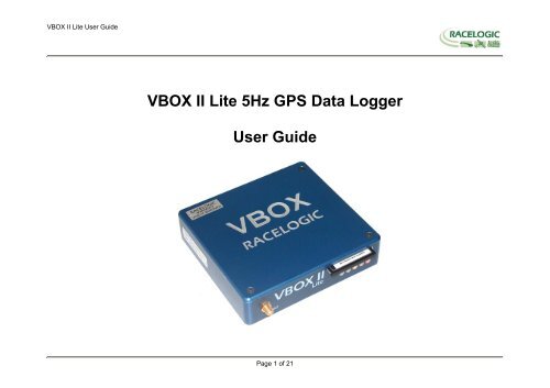
<strong>VBOX</strong> <strong>II</strong> <strong>Lite</strong> <strong>5Hz</strong> <strong>GPS</strong> <strong>Data</strong> <strong>Logger</strong><br />
<strong>User</strong> <strong>Guide</strong><br />
Page 1 of 21
<strong>VBOX</strong> <strong>II</strong> <strong>Lite</strong> <strong>User</strong> <strong>Guide</strong><br />
<strong>VBOX</strong> <strong>II</strong> LITE OVERVIEW .................................................................................................................................................................. 4<br />
INTRODUCTION................................................................................................................................................................................. 5<br />
FEATURES......................................................................................................................................................................................... 5<br />
STANDARD INVENTORY .................................................................................................................................................................. 6<br />
OPTIONAL ACCESSORIES............................................................................................................................................................... 6<br />
OPERATION....................................................................................................................................................................................... 7<br />
GETTING STARTED ........................................................................................................................................................................ 12<br />
<strong>VBOX</strong> <strong>II</strong> LITE ‘.VBO’ FILE FORMAT................................................................................................................................................ 14<br />
<strong>VBOX</strong>.EXE SOFTWARE .................................................................................................................................................................. 15<br />
FIRMWARE UPGRADES ................................................................................................................................................................. 16<br />
SPECIFICATION............................................................................................................................................................................... 17<br />
CONNECTION DATA ....................................................................................................................................................................... 18<br />
CAN BUS DATA FORMAT............................................................................................................................................................... 20<br />
CONTACT INFORMATION .............................................................................................................................................................. 21<br />
Page 2 of 21
<strong>VBOX</strong> <strong>II</strong> <strong>Lite</strong> <strong>User</strong> <strong>Guide</strong><br />
EC Declaration of Conformity<br />
We declare that this product has been tested to and meet the requirements of:<br />
EC Directive 2004/104/EC<br />
“Adapting to Technical Progress Council directive 72/245/EEC relating to the radio interference (Electromagnetic Compatibility) of vehicles and<br />
amending directive 70/156/EEC on the approximation of the laws of the member states relating to the type-approval of motor vehicles and their<br />
trailers.”<br />
And has also been assessed, via Technical Construction File, by an independent DTI Competent Body and found to be in conformance with the<br />
essential requirements of:<br />
EC Directive 89/336/EEC (and amending directives)<br />
“Council Directive of 03 May 1989 on the approximation of the laws of the member states relating to electromagnetic compatibility.”<br />
DTI Competent Body responsible for issuing certificate of compliance:<br />
3C Test Ltd,<br />
Silverstone Technology Park,<br />
Silverstone,<br />
Northants<br />
NN12 8GX<br />
Page 3 of 21
<strong>VBOX</strong> <strong>II</strong> <strong>Lite</strong> <strong>User</strong> <strong>Guide</strong><br />
<strong>VBOX</strong> <strong>II</strong> <strong>Lite</strong> Overview<br />
Page 4 of 21
<strong>VBOX</strong> <strong>II</strong> <strong>Lite</strong> <strong>User</strong> <strong>Guide</strong><br />
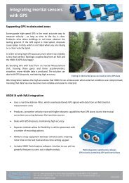
Introduction<br />
The <strong>VBOX</strong> <strong>II</strong> <strong>Lite</strong> represents the 2 nd generation of <strong>GPS</strong> data logging system from <strong>Racelogic</strong>. Using a powerful <strong>GPS</strong> engine, the <strong>VBOX</strong> <strong>II</strong> <strong>Lite</strong> can log <strong>GPS</strong><br />
and other data at <strong>5Hz</strong>. The logged data is stored directly onto a compact flash card for easy transfer to a PC.<br />
The <strong>VBOX</strong> <strong>II</strong> <strong>Lite</strong> is compatible with all of the existing peripherals including the Multifunction display, ADC03, TC8, FIM03 and Yaw rate sensor.<br />
Features<br />
• Non-contact <strong>5Hz</strong> speed and distance measurement using <strong>GPS</strong><br />
• 1 x CAN Bus interface<br />
• RS-232 serial interface<br />
• Compact Flash Interface<br />
• Trigger / Event marker input<br />
• Input Voltage 6V to 18V operating range<br />
• Logging rate selectable from <strong>5Hz</strong>, 2Hz, 1Hz, 0.<strong>5Hz</strong>, or 20Hz / 10Hz<br />
interpolated<br />
Page 5 of 21
<strong>VBOX</strong> <strong>II</strong> <strong>Lite</strong> <strong>User</strong> <strong>Guide</strong><br />
Standard Inventory<br />
Description Qty <strong>Racelogic</strong> Part #<br />
<strong>VBOX</strong> <strong>II</strong> <strong>Lite</strong> 1 VB2L<br />
Cigar Lighter adaptor 1 RLVBCAB10<br />
<strong>GPS</strong> Magnetic Aerial 1 RLVBACS015<br />
32Mb Compact Flash Card 1 RLVBACS005<br />
PCMCIA Compact Flash Adaptor 1 RLVBACS028<br />
CD ROM containing <strong>VBOX</strong> software 1 RLVBACS030<br />
Serial PC Cable 1 RLVBCAB01<br />
<strong>User</strong> Manual 1 RLVBACS031<br />
Padded Carrying Case 1 RLVBACS016<br />
Optional Accessories<br />
Description <strong>Racelogic</strong> Part #<br />
4.5Ah battery pack<br />
RLVBACS012<br />
Mains Charger<br />
RLVBACS020<br />
Brake Pedal Trigger<br />
RLVBACS004<br />
Hand-held brake trigger<br />
RLVBACS009<br />
Logging Start/Stop Switch<br />
RLVBACS010<br />
Multifunction Display<br />
RLVBDSP03<br />
8 Channel (16bit) Analogue Interface RLVBADC03<br />
8 Channel (10bit) Analogue Interface RLVBADC02<br />
4 Channel Frequency Input Module RLVBFIM03<br />
8 Channel Vehicle CAN Interface RLVBCAN01<br />
8 Channel Thermocouple Interface RLVBTC8<br />
Can to Analogue Output Module<br />
RLVBDAC01<br />
Single Yaw Rate Sensor + 2 axis G Sensor<br />
RLVBYAW02<br />
Inertial Measurement Unit. 3 Yaw Rate Sensors & 3 accelerometers RLVBIMU01<br />
Page 6 of 21
<strong>VBOX</strong> <strong>II</strong> <strong>Lite</strong> <strong>User</strong> <strong>Guide</strong><br />
Operation<br />
Power<br />
The <strong>VBOX</strong> <strong>Lite</strong> can be powered from a wide range of voltage sources including the supplied Vehicle Cigar adapter, or other source provided by the user. The<br />
maximum operating voltage input must not exceed 18V DC. Failure to observe this could result in damage to the <strong>VBOX</strong>.<br />
As an optional extra a battery pack is available from <strong>Racelogic</strong> RLVBACS012.<br />
The battery pack is a 6v 3.8amp hour Nickel Metal Hydride unit, with a built in charging and monitoring circuit.<br />
The battery is plugged into the two pin power socket on the front of the <strong>VBOX</strong> to provide power for up to 6<br />
hours (4 hours with the display attached).<br />
The battery pack can be charged via two methods, either by plugging the <strong>VBOX</strong> cigar lighter adapter into the<br />
pack, or by using the mains charger. The battery pack can be either discharged fully and then re-charged, or<br />
partially discharged and then re-charged, there is no memory effect on NiMh batteries.<br />
To protect the battery cells from damage, the battery will only charge when the temperature range is between 0<br />
& 46°C. If whilst charging the internal temperature of the battery reaches 46°C, the charge will be turned off<br />
until the internal temperature reduces to 43°C and the charge status led (25% 50% , 75% or 100% ) will flash.<br />
The charge will then automatically restart.<br />
Whilst charging, the 25%, 50%, 75% and 100% will illuminate in succession to give an indication of the total charge time. When the battery is fully charged,<br />
the 100% led will remain illuminated, and the charging led will turn off. Occasionally the battery will turn the charging back on to keep the battery at full<br />
capacity. To check the state of the battery charge; press and hold in the white button on the side of the box. There are four LED's which will light up indicating<br />
how much charge is left in the battery. 100% LED indicating 100% charge, 75% led indicating up to 99% charge, 50% led indicating up to 74% and 25% led<br />
indicating up to 49% charge. When the battery is at a level not suitable for powering the <strong>VBOX</strong>, the 25% led will flash.<br />
The battery can be connected to a charger, and also the <strong>VBOX</strong> at the same time. This allows the battery to be charged whilst the external source is powering<br />
the <strong>VBOX</strong>. In such a situation, you can power the <strong>VBOX</strong> from the cigar lighter, with the battery acting as a back up if the ignition is turned off which<br />
sometimes stops the power to the cigar lighter.<br />
When the battery is close to fully discharged, the <strong>VBOX</strong> will give an audible warning by a slow series of beeps from the internal buzzer. You should have<br />
around 5 minutes of time left when these beeps begin.<br />
Page 7 of 21
<strong>VBOX</strong> <strong>II</strong> <strong>Lite</strong> <strong>User</strong> <strong>Guide</strong><br />
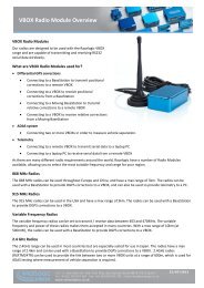
LED Indicators<br />
The green LED (ST) is used to indicate the number of satellites currently in lock. If the yellow<br />
LED (SC) is flashing whilst the green (ST) LED is off, then the <strong>VBOX</strong> has no satellite lock.<br />
If this is the case then check that you have the <strong>GPS</strong> antenna connector correctly fitted to the<br />
<strong>VBOX</strong>. Also check that the antenna has a clear view of the sky.<br />
The <strong>VBOX</strong> will normally lock onto satellites within 30 seconds of power up. However on its first<br />
use it can take up to 20 minutes to acquire satellite lock.<br />
The yellow LED (SC) flashes to indicate start of count. When satellite lock occurs the number of<br />
green LED flashes between yellow flashes indicates the number of satellites in lock.<br />
When a Compact Flash memory device is inserted into <strong>VBOX</strong> <strong>II</strong> <strong>Lite</strong> the blue LED (CF) will flash<br />
to indicate that the <strong>VBOX</strong> is writing to the device.<br />
The amber LED is used to indicate either CAN activity (CN) or if the unit is a D<strong>GPS</strong> version (DG), then this LED will come on when D<strong>GPS</strong> lock has been<br />
successful.<br />
The following diagram shows an example of SAT LED pulse sequence.<br />
Sequence showing 1 Satellite<br />
Sequence showing 4 Satellites<br />
1 1 1 1<br />
Delay 1 2 3 4 Delay 1 2 3 4<br />
Sequence showing 0 Satellites<br />
Delay (Approximately 1 second ) Delay (Approximately 1 second )<br />
Page 8 of 21
<strong>VBOX</strong> <strong>II</strong> <strong>Lite</strong> <strong>User</strong> <strong>Guide</strong><br />
Memory Cards<br />
The <strong>VBOX</strong> <strong>II</strong> <strong>Lite</strong> can accept Type-I compact flash memory cards. The memory cards must be formatted using FAT or FAT16 but not FAT32. This option is<br />
normally selectable when formatting the memory card in a card reader connected to a PC.<br />
When logging data to compact flash the blue CF LED will flash or be constantly illuminated. It is important not to remove the flash card while the blue LED is<br />
illuminated. If the card is removed while the <strong>VBOX</strong> is writing data to it, there is a risk that the data file may be corrupted resulting in loss of data. If ‘Log only<br />
when moving’ is the logging mode selected then wait a short time after the vehicle has stopped for the Blue CF LED to go out. If ‘Log only when moving’ is<br />
not selected i.e. the <strong>VBOX</strong> is continuously logging then press the Start/stop logging switch if connected or enter <strong>VBOX</strong> setup in the <strong>VBOX</strong> software to stop the<br />
<strong>VBOX</strong> logging data to the compact flash card.<br />
NOTE If you cannot do either of the above then just remove the card. If however the file is reported as corrupt by the <strong>VBOX</strong> software then load the file into<br />
Notepad and go to the end of the file. It is usual in this case that the last entry is corrupt, so delete it and re-save the file.<br />
<strong>GPS</strong> Antenna<br />
The <strong>GPS</strong> Antenna supplied with the <strong>VBOX</strong> <strong>II</strong> <strong>Lite</strong> is a 5v active antenna. For the best possible signal<br />
quality, it is important to maintain a clean connection between the antenna and the <strong>VBOX</strong>. Before<br />
fixing the antenna to the <strong>VBOX</strong>, ensure that there are no dust particles in either connector.<br />
Replacement antennas are available by contacting your <strong>VBOX</strong> distributor.<br />
The antenna is a magnetic mounting type for quick and simple mounting to the vehicle roof. For<br />
optimum <strong>GPS</strong> signal reception, make sure that the antenna is fitted to the highest point of the vehicle<br />
away from any obstructions that may block satellite reception. The <strong>GPS</strong> antenna works best with a<br />
metal ground plane underneath (eg. Vehicle roof).<br />
Please also note that when using any <strong>GPS</strong> equipment, a clear sky view is important. Objects in the<br />
surrounding area such and tall buildings or trees can block the <strong>GPS</strong> signal causing a reduction or loss<br />
in the number of satellites being tracked.<br />
Page 9 of 21
<strong>VBOX</strong> <strong>II</strong> <strong>Lite</strong> <strong>User</strong> <strong>Guide</strong><br />
Digital Inputs<br />
The DIGITAL INPUT (Socket 4) contains the two digital inputs for the <strong>VBOX</strong> <strong>II</strong> <strong>Lite</strong>. Digital input 1 is also referred to as the trigger / event marker input.<br />
A hand-held trigger is available to allow the user to record marker events in the <strong>VBOX</strong> <strong>II</strong> <strong>Lite</strong> data file.<br />
A remote logging on/off switch is also available.<br />
If you wish to use both digital inputs at the same time, you will require a 3way digital splitter (RLVBACS027).<br />
Page 10 of 21
<strong>VBOX</strong> <strong>II</strong> <strong>Lite</strong> <strong>User</strong> <strong>Guide</strong><br />
CAN / RS232 Ports<br />
The <strong>VBOX</strong> <strong>II</strong> <strong>Lite</strong> is equipped with a CAN Bus interface and a RS232 serial port. The RS232 port is used for all communication between the <strong>VBOX</strong> and laptop<br />
PC. The RS232 port is in Socket 5 on the <strong>VBOX</strong> <strong>II</strong> <strong>Lite</strong>. The RS232 port is able to transmit live data from the <strong>VBOX</strong> to the PC for viewing and performing realtime<br />
tests.<br />
The CAN Bus port is in Socket 2 of the <strong>VBOX</strong> <strong>II</strong> <strong>Lite</strong>. The function of this port is configurable by the user for use by either <strong>Racelogic</strong> modules (Internal mode)<br />
or the users own CAN Bus equipment (External mode). See the section ‘Setup’ in the <strong>VBOX</strong> software manual.<br />
The CAN Bus port also contains a secondary RS232 port for direct connections to the <strong>GPS</strong> engine for Local D<strong>GPS</strong> correction connection.<br />
Page 11 of 21
<strong>VBOX</strong> <strong>II</strong> <strong>Lite</strong> <strong>User</strong> <strong>Guide</strong><br />
Getting Started<br />
Required equipment (All supplied as standard unless specified)<br />
<br />
<br />
<br />
<br />
<br />
<br />
<br />
<strong>VBOX</strong> <strong>II</strong> <strong>Lite</strong><br />
Fully charged battery pack or Cigar lighter 12v adapter lead<br />
<strong>GPS</strong> Antenna<br />
Blank Compact Flash Card<br />
RS232 Cable<br />
<strong>VBOX</strong> Software CD<br />
Laptop PC(not supplied)<br />
1.Install Software 2.Place <strong>VBOX</strong> in vehicle 3.Fit antenna connector to <strong>VBOX</strong><br />
4. Mount <strong>GPS</strong> antenna on vehicle roof 5.Connect serial cable (CAB01) to laptop 6. Connect other end of serial cable to <strong>VBOX</strong><br />
Page 12 of 21
<strong>VBOX</strong> <strong>II</strong> <strong>Lite</strong> <strong>User</strong> <strong>Guide</strong><br />
7. Connect the power cable/ battery pack to the<br />
<strong>VBOX</strong><br />
8. If using 12v power cable, connect to vehicle<br />
9. With the power applied, the red PWR led should illuminate. The <strong>VBOX</strong> <strong>II</strong> <strong>Lite</strong> will start<br />
searching for satellites. The ST led will indicate the number of satellites currently in lock.<br />
For best results ensure the <strong>VBOX</strong> has acquired a lock on 5 or more satellites, essential for<br />
quality signal reception. When using the <strong>VBOX</strong> for the first time or when using the <strong>VBOX</strong><br />
after a long period of time, allow the <strong>VBOX</strong> to sit for between 5 and 10 minutes to recollect<br />
data needed to track satellites.<br />
As the vehicle begins moving, the blue CF led should begin to flash as data is recorded to<br />
compact flash, if inserted. When the vehicle comes to a stop, the blue CF led should<br />
extinguish. The card can now be removed and the data transferred onto the PC for<br />
analysis. If no compact flash card is fitted then data will be recorded to the internal RAM.<br />
NOTE before using the Internal RAM, the RAM should be cleared. See section ‘Setup’ of<br />
the <strong>VBOX</strong> Software manual.<br />
Page 13 of 21
<strong>VBOX</strong> <strong>II</strong> <strong>Lite</strong> <strong>User</strong> <strong>Guide</strong><br />
<strong>VBOX</strong> <strong>II</strong> <strong>Lite</strong> ‘.VBO’ File Format<br />
The <strong>VBOX</strong> <strong>II</strong> <strong>Lite</strong> data files are saved in standard space de-limited text<br />
format. This allows the data to easily be imported into third party applications<br />
such as word processors or spreadsheets. The files each contain a header<br />
section before the main data that describes the channel content and<br />
information about the <strong>VBOX</strong><strong>II</strong> such as serial number and firmware version.<br />
The [Column names] parameter specifies the data in each column of the data<br />
section.<br />
An example of a <strong>VBOX</strong> VBO file is shown on the right.<br />
File created on 15/04/2004 @ 08:21<br />
[header]<br />
satellites<br />
time<br />
latitude<br />
longitude<br />
velocity knots<br />
heading<br />
height<br />
Vertical velocity m/s<br />
[channel units]<br />
[comments]<br />
(c)2003 <strong>Racelogic</strong><br />
VBox<strong>II</strong> Version4.2d<br />
Serial Number: 004866<br />
Log Rate (Hz) : 20.00<br />
Software Version :-8.1.4 (build45)<br />
[column names]<br />
sats time lat long velocity heading height vert-vel<br />
[data]<br />
004 072148.26 +3119.408424 +00062.635139 015.13 356.06 +00155.27 -00000.22<br />
004 072148.27 +3119.408592 +00062.635104 015.17 356.02 +00147.93 -00000.37<br />
004 072148.28 +3119.408629 +00062.635108 015.09 355.92 +00147.92 -00000.40<br />
004 072148.29 +3119.408669 +00062.635115 014.98 355.64 +00147.92 -00000.35<br />
004 072148.30 +3119.408711 +00062.635119 015.00 355.87 +00147.91 -00000.47<br />
004 072148.31 +3119.408753 +00062.635122 015.03 356.11 +00147.90 -00000.61<br />
004 072148.32 +3119.408797 +00062.635125 015.16 356.48 +00147.88 -00000.84<br />
004 072148.33 +3119.408837 +00062.635130 015.06 356.32 +00147.88 -00000.67<br />
004 072148.34 +3119.408874 +00062.635138 014.84 355.81 +00147.91 -00000.14<br />
004 072148.35 +3119.408919 +00062.635144 015.03 355.84 +00147.90 -00000.28<br />
004 072148.36 +3119.408968 +00062.635147 015.42 356.17 +00147.87 -00000.66<br />
004 072148.37 +3119.409013 +00062.635148 015.56 356.72 +00147.87 -00000.69<br />
Page 14 of 21
<strong>VBOX</strong> <strong>II</strong> <strong>Lite</strong> <strong>User</strong> <strong>Guide</strong><br />
<strong>VBOX</strong>.EXE Software<br />
The <strong>VBOX</strong>.EXE software is used for configuration of the <strong>VBOX</strong> <strong>II</strong><br />
<strong>Lite</strong> and also for analysis of the VBO data files.<br />
For further information on the <strong>VBOX</strong>.EXE software refer to the<br />
<strong>VBOX</strong> Software manual supplied with <strong>VBOX</strong> <strong>II</strong> <strong>Lite</strong>.<br />
Page 15 of 21
<strong>VBOX</strong> <strong>II</strong> <strong>Lite</strong> <strong>User</strong> <strong>Guide</strong><br />
Firmware Upgrades<br />
Firmware refers to the operating software inside the <strong>VBOX</strong> <strong>II</strong> <strong>Lite</strong>. The firmware is responsible for all of the functions within the <strong>VBOX</strong> and from time to time,<br />
firmware updates will be released by <strong>Racelogic</strong> to improve or enhance the way that the <strong>VBOX</strong> works. The latest firmware will always be available on the<br />
<strong>Racelogic</strong> web site in the downloads directory:-<br />
http://www.racelogic.co.uk/2003/vbox/downloads.htm<br />
It is recommended to check the web site periodically for updates. The <strong>VBOX</strong> <strong>II</strong> <strong>Lite</strong> upgrade files have a “.ruf” file extension. To upgrade the <strong>VBOX</strong> <strong>II</strong> <strong>Lite</strong><br />
firmware, download the latest firmware file from the <strong>Racelogic</strong> web site and copy this file onto your PC. If you have done a full <strong>VBOX</strong> CD installation then you<br />
will have the upgrade programme automatically installed in the Utilities folder of <strong>VBOX</strong> folder. If not then this can also downloaded from the website.<br />
Connect you pc to the <strong>VBOX</strong> via the <strong>VBOX</strong> serial lead and apply power to the <strong>VBOX</strong>.<br />
Either ‘double click’ on the .ruf upgrade file, which auto runs the upgrader software, or run the upgrader software and load in the .ruf firmware upgrade file.<br />
Then follow the onscreen instructions and the <strong>VBOX</strong> firmware will be upgraded. At the end of the process power down the <strong>VBOX</strong> when prompted, before<br />
further use<br />
During the upgrade process an upgrade log file will have been created. This log file can be emailed to the support address below should any problems arise.<br />
If you have any questions regarding upgrade of <strong>VBOX</strong>, please do not hesitate to contact support@racelogic.co.uk<br />
Page 16 of 21
<strong>VBOX</strong> <strong>II</strong> <strong>Lite</strong> <strong>User</strong> <strong>Guide</strong><br />
Specification<br />
<strong>GPS</strong><br />
Velocity Distance<br />
Accuracy 0.2 Km/h (averaged over 4<br />
Accuracy<br />
0.05% (
<strong>VBOX</strong> <strong>II</strong> <strong>Lite</strong> <strong>User</strong> <strong>Guide</strong><br />
Connection <strong>Data</strong><br />
2 pin LEMO socket 3 pin LEMO socket 5 pin LEMO socket<br />
Connector 1 POWER Type Lemo 2 pin<br />
PIN In/Out Description Range<br />
1 I Power + 6V to 18V<br />
2 I Ground 0V<br />
Chassis Ground<br />
Page 18 of 21
<strong>VBOX</strong> <strong>II</strong> <strong>Lite</strong> <strong>User</strong> <strong>Guide</strong><br />
Connector 2 CAN BUS Type Lemo 5 pin<br />
PIN In/Out Description Range<br />
1 O RS232 Tx (PORT B Local D<strong>GPS</strong>) ±12v<br />
2 I RS232 Rx (PORT B Local D<strong>GPS</strong>) ±12v<br />
3 I/O CAN Bus<br />
4 I/O CAN Bus<br />
5 O +V Power<br />
Chassis Ground<br />
Connector 3 RS232 Type Lemo 5 pin<br />
PIN In/Out Description Range<br />
1 O RS232 Tx Serial <strong>Data</strong> Transmit ±12v<br />
2 I RS232 Rx Serial <strong>Data</strong> Receive ±12v<br />
3 - -<br />
4 - -<br />
5 O +V Power<br />
Chassis Ground<br />
Connector 4 DIGITAL INPUT Type Lemo 3 pin<br />
PIN In/Out Description Range<br />
1 O Ground<br />
2 I Digital Input 2. Start/Stop Logging 0V to 5V<br />
3 I Digital Input 1. Brake Trigger 0V to 5V<br />
Chassis Ground<br />
Antenna connector<br />
Connector ANT Type SMA<br />
PIN In/Out Description Range<br />
Center - RF Signal / Power for active antenna<br />
Chassis - Ground<br />
Page 19 of 21
<strong>VBOX</strong> <strong>II</strong> <strong>Lite</strong> <strong>User</strong> <strong>Guide</strong><br />
CAN Bus data format<br />
Format<br />
Motorola<br />
ID** Update <strong>Data</strong> Bytes<br />
rate 1 2 3 4 5 6 7 8<br />
0x301 50ms (1) Sats in (2) Time since midnight UTC (3) Position – Latitude DDMM.MMMMM<br />
view<br />
0x302 50ms (4) Position – Longitude DDMMM.MMMMM (5) Velocity. (Knots) (6) Heading. (Degrees)<br />
0x303 50ms (7) Altitude. WGS 84. (Metres) (8) Vertical velocity. (M/S) Unused (9) Status (10) Status<br />
0x304 50ms Unused (11) Longitudinal Accel. (G) (12) Lateral Accel. (G)<br />
0x305 50ms (13) Distance. (Meters)<br />
**Default Identifiers. The identifier values can be changed using the configuration software.<br />
(1) If Satellites in view < 3 then only Identifier 0x301 transmitted and bytes 2 to 8 are set to 0x00.<br />
(2) Time since midnight. This is a count of 10mS intervals since midnight UTC. (5383690 = 53836.90 seconds since midnight or 14 hours, 57<br />
minutes and 16.90 seconds)<br />
(3) Position, Latitude * 100,000 (515924579 = 51 Degrees, 59.24579 Minutes North). Latitude highest bit indicates north/south hemisphere.<br />
0=north, 1=south, Bit 7 in Status is also set.<br />
(4) Position, Longitude * 100,000 (5882246 = 0 Degrees, 58.82246 Minutes West). Longitude highest bit indicates east/west of Greenwich<br />
meridian. 0=west,1=east. Bit 6 in Status is also set.<br />
(5) Velocity, 0.01 knots per bit.<br />
(6) Heading, 0.01° per bit.<br />
(7) Altitude, 0.01 meters per bit, signed.<br />
(8) Vertical Velocity, 0.01 m/s per bit, signed.<br />
(9) Status. 8 bit unsigned char. Bit 0=<strong>VBOX</strong> <strong>Lite</strong>, Bit 1=Open or Closed CAN Bus (1=open), 2=<strong>VBOX</strong>3<br />
(10) Status is an 8 bit unsigned char. Bit 0 is always set, Bit 3=brake test started, Bit 4 = Brake trigger active, Bit 5 = D<strong>GPS</strong> active<br />
(11) Longitudinal Acceleration, 0.01G per bit, signed.<br />
(11) Lateral Acceleration, 0.01G per bit, signed.<br />
(13) Distance, 0.000078125 meters per bit, unsigned.<br />
The <strong>VBOX</strong> CAN database is available in Vector <strong>Data</strong>base (DBC File) format on request from <strong>Racelogic</strong><br />
Page 20 of 21
<strong>VBOX</strong> <strong>II</strong> <strong>Lite</strong> <strong>User</strong> <strong>Guide</strong><br />
Contact Information<br />
<strong>Racelogic</strong> Ltd<br />
Unit 10 Swan Business Centre<br />
Osier Way<br />
Buckingham<br />
MK18 1TB<br />
UK<br />
Tel: +44 (0) 1280 823803<br />
Fax: +44 (0) 1280 823595<br />
Email: support@racelogic.co.uk<br />
Web: www.racelogic.co.uk<br />
Revision Date Description Author<br />
1 21/10/2005 First Draft JDH<br />
2 18/09/2006 Addition of text describing Digital inputs KB<br />
3 05/06/2007 Inclusion of Declaration of Conformity Statement CAS<br />
4 07/11/2007 Correction to CAN format table KB<br />
5 03/12/2007 Addition of Format: Motorola to CAN Bus <strong>Data</strong> Format table NT<br />
6 30/04/2008 Updated <strong>Racelogic</strong> contact information JH<br />
Page 21 of 21