Chapter 15 Power Supplies - Webstaff.kmutt.ac.th
Chapter 15 Power Supplies - Webstaff.kmutt.ac.th
Chapter 15 Power Supplies - Webstaff.kmutt.ac.th

Create successful ePaper yourself
Turn your PDF publications into a flip-book with our unique Google optimized e-Paper software.
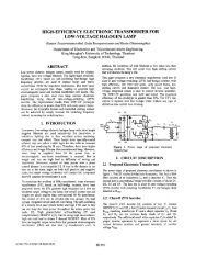
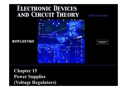
<strong>Chapter</strong> <strong>15</strong><br />
<strong>Power</strong> <strong>Supplies</strong><br />
(Voltage Regulators)
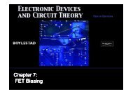
<strong>Power</strong> Supply Diagram<br />
Electronic Devices and Circuit Theory, 10/e<br />
Robert L. Boylestad and Louis Nashelsky<br />
2<br />
Copyright ©2009 by Pearson Education, Inc.<br />
Upper Saddle River, New Jersey 07458 • All rights reserved.
Filter Circuits<br />
• The output from <strong>th</strong>e rectifier section is a<br />
pulsating DC.<br />
• The filter circuit reduces <strong>th</strong>e peak-to-peak<br />
pulses to a small ripple voltage.<br />
Electronic Devices and Circuit Theory, 10/e<br />
Robert L. Boylestad and Louis Nashelsky<br />
3<br />
Copyright ©2009 by Pearson Education, Inc.<br />
Upper Saddle River, New Jersey 07458 • All rights reserved.
Ripple F<strong>ac</strong>tor<br />
After <strong>th</strong>e filter circuit a small<br />
amount of AC is still<br />
remaining. The amount of<br />
ripple voltage can be rated in<br />
terms of ripple f<strong>ac</strong>tor (r).<br />
%r<br />
=<br />
ripple voltage (rms)<br />
dc voltage<br />
=<br />
V<br />
r(rms<br />
V<br />
dc<br />
)<br />
× 100<br />
Electronic Devices and Circuit Theory, 10/e<br />
Robert L. Boylestad and Louis Nashelsky<br />
4<br />
Copyright ©2009 by Pearson Education, Inc.<br />
Upper Saddle River, New Jersey 07458 • All rights reserved.
Rectifier Ripple F<strong>ac</strong>tor<br />
Half-Wave<br />
Full-Wave<br />
DC output:<br />
DC output:<br />
V dc = 0.318V m<br />
V dc = 0.636V m<br />
AC ripple output:<br />
AC ripple output:<br />
V =<br />
0.385V<br />
r(rms) 0.385V m<br />
V =<br />
0.308V<br />
r(rms) 0.308V m<br />
Ripple f<strong>ac</strong>tor:<br />
Ripple f<strong>ac</strong>tor:<br />
%r<br />
=<br />
=<br />
V<br />
r(rms)<br />
V<br />
dc<br />
0.385V<br />
0.318V<br />
× 100<br />
m<br />
m<br />
× 100<br />
=<br />
121%<br />
%r<br />
=<br />
=<br />
V<br />
r(rms)<br />
V<br />
dc<br />
0.308<br />
0.636<br />
Vm<br />
Vm<br />
× 100<br />
× 100<br />
=<br />
48%<br />
Electronic Devices and Circuit Theory, 10/e<br />
Robert L. Boylestad and Louis Nashelsky<br />
5<br />
Copyright ©2009 by Pearson Education, Inc.<br />
Upper Saddle River, New Jersey 07458 • All rights reserved.
Types of Filter Circuits<br />
Cap<strong>ac</strong>itor Filter<br />
RC Filter<br />
Electronic Devices and Circuit Theory, 10/e<br />
Robert L. Boylestad and Louis Nashelsky<br />
6<br />
Copyright ©2009 by Pearson Education, Inc.<br />
Upper Saddle River, New Jersey 07458 • All rights reserved.
Cap<strong>ac</strong>itor Filter<br />
Ripple voltage<br />
V<br />
4<br />
I<br />
3fC<br />
2.4I<br />
dc dc<br />
r(rms) = = =<br />
C<br />
2.4V<br />
R<br />
The larger <strong>th</strong>e cap<strong>ac</strong>itor <strong>th</strong>e<br />
smaller <strong>th</strong>e ripple voltage.<br />
L<br />
dc<br />
C<br />
DC output<br />
V<br />
dc<br />
=<br />
V<br />
m<br />
−<br />
I<br />
dc<br />
4fC<br />
=<br />
V<br />
m<br />
−<br />
4.17I<br />
C<br />
dc<br />
Ripple f<strong>ac</strong>tor<br />
%r<br />
=<br />
V<br />
r(rms)<br />
V<br />
dc<br />
× 100<br />
=<br />
2.4I<br />
CV<br />
dc<br />
dc<br />
× 100<br />
=<br />
2.4<br />
RLC<br />
× 100<br />
Electronic Devices and Circuit Theory, 10/e<br />
Robert L. Boylestad and Louis Nashelsky<br />
7<br />
Copyright ©2009 by Pearson Education, Inc.<br />
Upper Saddle River, New Jersey 07458 • All rights reserved.
Diode Ratings wi<strong>th</strong> Cap<strong>ac</strong>itor Filter<br />
The size of <strong>th</strong>e cap<strong>ac</strong>itor increases <strong>th</strong>e current drawn <strong>th</strong>rough <strong>th</strong>e diodes—<br />
<strong>th</strong>e larger <strong>th</strong>e cap<strong>ac</strong>itance, <strong>th</strong>e greater <strong>th</strong>e amount of current.<br />
Peak Current vs. Cap<strong>ac</strong>itance:<br />
CV<br />
I =<br />
t<br />
where<br />
C = cap<strong>ac</strong>itance<br />
V = change in cap<strong>ac</strong>itor voltage during charge/discharge<br />
t = <strong>th</strong>e charge/discharge time<br />
Electronic Devices and Circuit Theory, 10/e<br />
Robert L. Boylestad and Louis Nashelsky<br />
8<br />
Copyright ©2009 by Pearson Education, Inc.<br />
Upper Saddle River, New Jersey 07458 • All rights reserved.
RC Filter Circuit<br />
Adding an RC section fur<strong>th</strong>er<br />
reduces <strong>th</strong>e ripple voltage and<br />
decrease <strong>th</strong>e surge current<br />
<strong>th</strong>rough <strong>th</strong>e diodes.<br />
V′<br />
r(rms)<br />
≈<br />
X<br />
C<br />
R<br />
V<br />
r(rms)<br />
%V<br />
V′ r(rms) = ripple voltage after <strong>th</strong>e RC filter<br />
V r(rms) = ripple voltage before <strong>th</strong>e RC filter<br />
R = resistor in <strong>th</strong>e added RC filter<br />
X C = re<strong>ac</strong>tance of <strong>th</strong>e cap<strong>ac</strong>itor in <strong>th</strong>e added RC filter<br />
V<br />
− V<br />
NL FL<br />
R =<br />
×<br />
VFL<br />
V NL = no-load voltage<br />
V FL = full-load voltage<br />
100%<br />
Electronic Devices and Circuit Theory, 10/e<br />
Robert L. Boylestad and Louis Nashelsky<br />
9<br />
Copyright ©2009 by Pearson Education, Inc.<br />
Upper Saddle River, New Jersey 07458 • All rights reserved.
Voltage Regulation Circuits<br />
There are two common types of circuitry for voltage<br />
regulation:<br />
• Discrete Transistors<br />
• IC’s<br />
Electronic Devices and Circuit Theory, 10/e<br />
Robert L. Boylestad and Louis Nashelsky<br />
10<br />
Copyright ©2009 by Pearson Education, Inc.<br />
Upper Saddle River, New Jersey 07458 • All rights reserved.
Discrete-Transistor Regulators<br />
Series voltage regulator<br />
Current-limiting circuit<br />
Shunt voltage regulator<br />
Electronic Devices and Circuit Theory, 10/e<br />
Robert L. Boylestad and Louis Nashelsky<br />
11<br />
Copyright ©2009 by Pearson Education, Inc.<br />
Upper Saddle River, New Jersey 07458 • All rights reserved.
Series Voltage Regulator Circuit<br />
The series element controls <strong>th</strong>e amount of <strong>th</strong>e input voltage <strong>th</strong>at gets to<br />
<strong>th</strong>e output.<br />
If <strong>th</strong>e output voltage increases (or decreases), <strong>th</strong>e comparator circuit<br />
provides a control signal to cause <strong>th</strong>e series control element to decrease<br />
(or increase) <strong>th</strong>e amount of <strong>th</strong>e output voltage.<br />
Electronic Devices and Circuit Theory, 10/e<br />
Robert L. Boylestad and Louis Nashelsky<br />
12<br />
Copyright ©2009 by Pearson Education, Inc.<br />
Upper Saddle River, New Jersey 07458 • All rights reserved.
Series Voltage Regulator Circuit<br />
• R 1 and R 2 <strong>ac</strong>t as <strong>th</strong>e sampling circuit<br />
• Zener provides <strong>th</strong>e reference voltage<br />
• Q 2 controls <strong>th</strong>e base current to Q 1<br />
• Q 1 maintains <strong>th</strong>e constant output<br />
voltage<br />
When <strong>th</strong>e output increases:<br />
When <strong>th</strong>e output decreases:<br />
1. The voltage at V 2 and V BE of Q 2<br />
increases<br />
2. The conduction of Q 2 increases<br />
3. The conduction of Q 1 decreases<br />
4. The output voltage decreases<br />
1. The voltage at V 2 and V BE of Q 2<br />
decreases<br />
2. The conduction of Q 2 decreases<br />
3. The conduction of Q 1 increases<br />
4. The output voltage increases<br />
Electronic Devices and Circuit Theory, 10/e<br />
Robert L. Boylestad and Louis Nashelsky<br />
13<br />
Copyright ©2009 by Pearson Education, Inc.<br />
Upper Saddle River, New Jersey 07458 • All rights reserved.
Series Voltage Regulator Circuit<br />
The op-amp compares <strong>th</strong>e<br />
Zener diode voltage wi<strong>th</strong><br />
<strong>th</strong>e output voltage (at R 1<br />
and R 2 ) and controls <strong>th</strong>e<br />
conduction of Q 1 .<br />
Electronic Devices and Circuit Theory, 10/e<br />
Robert L. Boylestad and Louis Nashelsky<br />
14<br />
Copyright ©2009 by Pearson Education, Inc.<br />
Upper Saddle River, New Jersey 07458 • All rights reserved.
Current-Limiting Circuit<br />
When I L increases:<br />
• The voltage <strong>ac</strong>ross R SC increases<br />
• The increasing voltage <strong>ac</strong>ross R SC drives Q 2 on<br />
• Conduction of Q 2 reduces current for Q 1 and <strong>th</strong>e load<br />
Electronic Devices and Circuit Theory, 10/e<br />
Robert L. Boylestad and Louis Nashelsky<br />
<strong>15</strong><br />
Copyright ©2009 by Pearson Education, Inc.<br />
Upper Saddle River, New Jersey 07458 • All rights reserved.
Shunt Voltage Regulator Circuit<br />
The shunt voltage regulator<br />
shunts current away from<br />
<strong>th</strong>e load.<br />
The load voltage is sampled and fed b<strong>ac</strong>k to a comparator circuit.<br />
If <strong>th</strong>e load voltage is too high, control circuitry shunts more<br />
current away from <strong>th</strong>e load.<br />
Electronic Devices and Circuit Theory, 10/e<br />
Robert L. Boylestad and Louis Nashelsky<br />
16<br />
Copyright ©2009 by Pearson Education, Inc.<br />
Upper Saddle River, New Jersey 07458 • All rights reserved.
Shunt Voltage Regulator Circuit<br />
When <strong>th</strong>e output voltage increases:<br />
• The Zener current increases<br />
• The conduction of Q 2 increases<br />
• The voltage drop at R s increases<br />
• The output voltage decreases<br />
When <strong>th</strong>e output voltage decreases:<br />
• The Zener current decreases<br />
• The conduction of Q 2 decreases<br />
• The voltage drop at R s decreases<br />
• The output voltage increases<br />
Electronic Devices and Circuit Theory, 10/e<br />
Robert L. Boylestad and Louis Nashelsky<br />
17<br />
Copyright ©2009 by Pearson Education, Inc.<br />
Upper Saddle River, New Jersey 07458 • All rights reserved.
Shunt Voltage Regulator Circuit<br />
Electronic Devices and Circuit Theory, 10/e<br />
Robert L. Boylestad and Louis Nashelsky<br />
18<br />
Copyright ©2009 by Pearson Education, Inc.<br />
Upper Saddle River, New Jersey 07458 • All rights reserved.
IC Voltage Regulators<br />
Regulator ICs contain:<br />
• Comparator circuit<br />
• Reference voltage<br />
• Control circuitry<br />
• Overload protection<br />
Types of <strong>th</strong>ree-terminal IC voltage regulators<br />
• Fixed positive voltage regulator<br />
• Fixed negative voltage regulator<br />
• Adjustable voltage regulator<br />
Electronic Devices and Circuit Theory, 10/e<br />
Robert L. Boylestad and Louis Nashelsky<br />
19<br />
Copyright ©2009 by Pearson Education, Inc.<br />
Upper Saddle River, New Jersey 07458 • All rights reserved.
Three-Terminal Terminal Voltage Regulators<br />
The specifications for <strong>th</strong>is IC indicate:<br />
• The range of input voltages <strong>th</strong>at can be regulated for a specific range of<br />
output voltage and load current<br />
• Load regulation—variation in output voltage wi<strong>th</strong> variations in load<br />
current<br />
• Line regulation—variation in output voltage wi<strong>th</strong> variations in input<br />
voltage<br />
Electronic Devices and Circuit Theory, 10/e<br />
Robert L. Boylestad and Louis Nashelsky<br />
20<br />
Copyright ©2009 by Pearson Education, Inc.<br />
Upper Saddle River, New Jersey 07458 • All rights reserved.
Fixed Positive Voltage Regulator<br />
These ICs provide a fixed positive output voltage.<br />
Electronic Devices and Circuit Theory, 10/e<br />
Robert L. Boylestad and Louis Nashelsky<br />
21<br />
Copyright ©2009 by Pearson Education, Inc.<br />
Upper Saddle River, New Jersey 07458 • All rights reserved.
Fixed Negative Voltage Regulator<br />
These ICs output a fixed negative output voltage.<br />
Electronic Devices and Circuit Theory, 10/e<br />
Robert L. Boylestad and Louis Nashelsky<br />
22<br />
Copyright ©2009 by Pearson Education, Inc.<br />
Upper Saddle River, New Jersey 07458 • All rights reserved.
Adjustable Voltage Regulator<br />
These regulators have<br />
adjustable output<br />
voltages.<br />
The output voltage is<br />
commonly selected<br />
using a potentiometer.<br />
Electronic Devices and Circuit Theory, 10/e<br />
Robert L. Boylestad and Louis Nashelsky<br />
23<br />
Copyright ©2009 by Pearson Education, Inc.<br />
Upper Saddle River, New Jersey 07458 • All rights reserved.
Pr<strong>ac</strong>tical <strong>Power</strong> <strong>Supplies</strong><br />
DC supply (linear power supplies)<br />
Chopper supply (switching power supplies)<br />
TV horizontal high voltage supply<br />
Battery chargers<br />
Electronic Devices and Circuit Theory, 10/e<br />
Robert L. Boylestad and Louis Nashelsky<br />
24<br />
Copyright ©2009 by Pearson Education, Inc.<br />
Upper Saddle River, New Jersey 07458 • All rights reserved.