DOE 2000. - Waste Isolation Pilot Plant - U.S. Department of Energy
DOE 2000. - Waste Isolation Pilot Plant - U.S. Department of Energy
DOE 2000. - Waste Isolation Pilot Plant - U.S. Department of Energy

You also want an ePaper? Increase the reach of your titles
YUMPU automatically turns print PDFs into web optimized ePapers that Google loves.
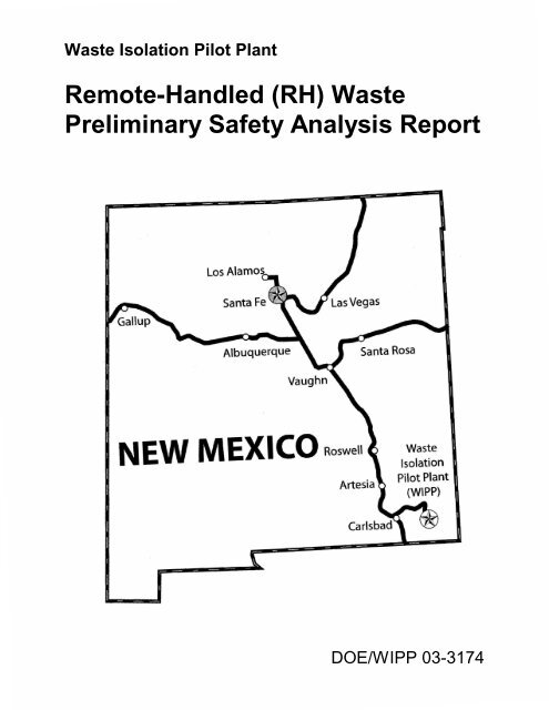
<strong>Waste</strong> <strong>Isolation</strong> <strong>Pilot</strong> <strong>Plant</strong><br />
Remote-Handled (RH) <strong>Waste</strong><br />
Preliminary Safety Analysis Report<br />
Los Alamos<br />
Albuquerque<br />
Santa Rosa<br />
NEW MEXICO Roswell<br />
<strong>Waste</strong><br />
<strong>Isolation</strong><br />
<strong>Pilot</strong> <strong>Plant</strong><br />
(WIPP)<br />
<strong>DOE</strong>/WIPP 03-3174
WIPP RH PSAR<br />
<strong>DOE</strong>/WIPP-03-3174<br />
CONTENTS<br />
CHAPTER<br />
TITLE<br />
1 EXECUTIVE SUMMARY<br />
2 SITE CHARACTERISTICS<br />
3 PRINCIPAL DESIGN AND SAFETY CRITERIA<br />
4 FACILITY DESIGN AND OPERATION<br />
5 HAZARD AND ACCIDENT ANALYSIS<br />
6 DERIVATION OF TECHNICAL SAFETY REQUIREMENTS<br />
7 RADIOLOGICAL AND HAZARDOUS MATERIAL PROTECTION<br />
8 INSTITUTIONAL PROGRAMS<br />
9 QUALITY ASSURANCE<br />
10 DECONTAMINATION AND DECOMMISSIONING<br />
APPENDIX A<br />
APPENDIX B<br />
APPENDIX C<br />
APPENDIX D<br />
APPENDIX E<br />
WASTE CONTAINER INVENTORY CALCULATIONS<br />
PLUTONIUM-239 EQUIVALENT ACTIVITY<br />
HAZOP SESSION SUMMARY TABLE<br />
DETERMINATION OF FREQUENCIES OF SELECTED ACCIDENTS<br />
SOURCE TERM/DOSE CALCULATIONS<br />
ATTACHMENT 1 <strong>DOE</strong>/WIPP-03-3178 WASTE ISOLATION PILOT PLANT<br />
REMOTE HANDLED (RH) PRELIMINARY TECHNICAL<br />
SAFETY REQUIREMENTS<br />
January 28, 2003
WIPP RH PSAR<br />
<strong>DOE</strong>/WIPP-03-3174<br />
This page intentionally blank<br />
ii January 28, 2003
WIPP RH PSAR<br />
<strong>DOE</strong>/WIPP-03-3174<br />
ACRONYMS<br />
AC<br />
AIHA<br />
AIS<br />
ALARA<br />
ANS<br />
ANSI<br />
ARF<br />
ARMS<br />
ASME<br />
BLM<br />
BR<br />
Bq<br />
C&C<br />
CA<br />
CAO<br />
CAM<br />
CCA<br />
CCDF<br />
CCTV<br />
CD<br />
CEDE<br />
CFR<br />
CH<br />
Ci<br />
CI<br />
CMR<br />
CMS<br />
D&D<br />
DAC<br />
DBA<br />
DBE<br />
DBT<br />
DCF<br />
<strong>DOE</strong><br />
<strong>DOE</strong>-EM<br />
DOI<br />
DOP<br />
DOT<br />
DR<br />
ECO<br />
EEG<br />
EEGL<br />
EFB<br />
EOC<br />
EPA<br />
ERDA<br />
ERPG<br />
Administrative Control<br />
American Industrial Hygiene Association<br />
Air Intake Shaft<br />
As Low As Reasonably Achievable<br />
American Nuclear Society<br />
American National Standard Institute<br />
Airborne Release Fraction<br />
Area Radiation Monitors<br />
American Society <strong>of</strong> Mechanical Engineers<br />
Bureau <strong>of</strong> Land Management<br />
Breathing Rate<br />
Becquerel<br />
Consultation and Cooperation<br />
Controlled Area<br />
Carlsbad Area Office (<strong>DOE</strong>)<br />
Continuous Air Monitor<br />
Consultation and Cooperation Agreement<br />
Complimentary Cumulative Distribution Function<br />
Closed Circuit Television<br />
Containers Damaged<br />
Committed Effective Dose Equivalent<br />
Code <strong>of</strong> Federal Regulations<br />
Contact Handled<br />
Curie<br />
Container Inventory<br />
Central Monitoring Room<br />
Central Monitoring System<br />
Decontamination and Decommissioning<br />
Derived Air Concentration<br />
Design Basis Accident<br />
Design Basis Earthquake<br />
Design Basis Tornado<br />
Dose Conversion Factor<br />
<strong>Department</strong> <strong>of</strong> <strong>Energy</strong><br />
<strong>Department</strong> <strong>of</strong> <strong>Energy</strong>, Office <strong>of</strong> Environmental Restoration<br />
<strong>Department</strong> <strong>of</strong> Interior<br />
Dioctylphthalate<br />
<strong>Department</strong> <strong>of</strong> Transportation<br />
Damage Ratio<br />
Engineering Change Order<br />
Environmental Evaluation Group<br />
Emergency Exposure Guidance Level<br />
Exhaust Filter Building<br />
Emergency Operations Center<br />
Environmental Protection Agency<br />
<strong>Energy</strong> Research and Development Administration<br />
Emergency Response Planning Guideline<br />
i January 28, 2003
WIPP RH PSAR<br />
<strong>DOE</strong>/WIPP-03-3174<br />
ACRONYMS<br />
ESH<br />
ERT<br />
FAS<br />
FEP<br />
FGE<br />
FEIS<br />
FLIRT<br />
FMEA<br />
FSEIS<br />
FY<br />
GM<br />
GPDD<br />
HAZOP<br />
HEP<br />
HEPA<br />
HVAC<br />
ICRP<br />
ICV<br />
IDLH<br />
LCO<br />
LCS<br />
LPF<br />
LPU<br />
LWA<br />
MAR<br />
MDC<br />
MEI<br />
MgO<br />
MOC<br />
MOI<br />
MRF<br />
MSDS<br />
MSHA<br />
NFPA<br />
NIST<br />
NMBMMR<br />
NMDG&F<br />
NRB<br />
NRC<br />
NVP<br />
OHP<br />
ORNL<br />
ORR<br />
OSHA<br />
PABX<br />
PA<br />
PEL<br />
Environment, Safety, and Health<br />
Emergency Response Team<br />
Fixed Air Sampler<br />
Features, Events, and Processes<br />
Fissile Gram Equivalent<br />
Final Environmental Impact Statement<br />
First Line Initial Response Team<br />
Failure Mode and Effects Analysis<br />
Final Supplement Environmental Impact Statement<br />
Fiscal Year<br />
General Manager<br />
General <strong>Plant</strong> System Design Description<br />
Hazard and Operability Study<br />
Human Error Probability<br />
High Efficiency Particulate Filter<br />
Heat, Ventilation, and Air Conditioning<br />
International Commission on Radiological Protection<br />
Inner Containment Vessel<br />
Immediately Dangerous to Life and Health<br />
Limiting Condition for Operation<br />
Limiting Control Setting<br />
Leakpath Factor<br />
Local Processing Unit<br />
Land Withdrawal Act<br />
Material at Risk<br />
Minimum Detectable Concentrations<br />
Maximally Exposed Individual<br />
Magnesium Oxide<br />
Management and Operating Contractor<br />
Maximally Exposed Off-site Individual<br />
Material Release Fraction<br />
Material Safety Data Sheet<br />
Mine Safety and Health Administration<br />
National Fire Protection Agency<br />
National Institute <strong>of</strong> Science and Technology<br />
New Mexico Bureau <strong>of</strong> Mines and Mineral Resources<br />
New Mexico <strong>Department</strong> <strong>of</strong> Game and Fish<br />
Nuclear Review Board<br />
Nuclear Regulatory Commission<br />
Natural Ventilation Pressure<br />
Operational Health Physics<br />
Oak Ridge National Laboratory<br />
Operational Readiness Review<br />
Occupational Safety and Health Administration<br />
Private Automatic Branch Exchange<br />
Public Address or Performance Assessment<br />
Permissible Exposure limit<br />
ii January 28, 2003
WIPP RH PSAR<br />
<strong>DOE</strong>/WIPP-03-3174<br />
ACRONYMS<br />
PE-Ci<br />
ppmv<br />
PSM<br />
Pu<br />
QA<br />
QAPD<br />
QC<br />
RADCON<br />
RBP<br />
RCRA<br />
rem<br />
REMS<br />
RF<br />
RFAR<br />
RH<br />
RBA<br />
RMA<br />
RMS<br />
ROD<br />
RWP<br />
SAR<br />
SCR<br />
SDD<br />
SEIS<br />
SH<br />
SOP<br />
SL<br />
SNL<br />
SPDV<br />
SPEGL<br />
SR<br />
SRS<br />
SSC<br />
STD<br />
Sv<br />
SWB<br />
TDOP<br />
TDS<br />
TEDE<br />
TEEL<br />
TLD<br />
TLV-C<br />
TLV-STEL<br />
TLV-TWA<br />
TRUPACT<br />
TRU<br />
TSC<br />
Plutonium Equivalent Curie<br />
Parts per Million Volume<br />
Process Safety Management<br />
Plutonium<br />
Quality Assurance<br />
Quality Assurance Program Description<br />
Quality Control<br />
Radiological Control<br />
Radiological Baseline Program<br />
Resource Conservation and Recovery Act<br />
roentgen equivalent man<br />
Radiation Effluent Monitoring System<br />
Respirable Fraction<br />
Radio Fire Alarm Reporter<br />
Remote Handled<br />
Radiological Buffer Area<br />
Radioactive Material Area<br />
Radiation Monitoring System<br />
Record <strong>of</strong> Decision<br />
Radiation Work Permit<br />
Safety Analysis Report<br />
Silicon Controlled Rectifier<br />
System Design Descriptions<br />
Supplement Environmental Impact Statement<br />
Salt Handling Shaft<br />
Standard Operating Procedure<br />
Safety Limit<br />
Sandia National Laboratory<br />
Site and Preliminary Design Validation<br />
Short-term Public Exposure Guidance Level<br />
Surveillance Requirement<br />
Savannah River Site<br />
System, Structure, and Component<br />
Standard<br />
Sievert<br />
Standard <strong>Waste</strong> Box<br />
Ten Drum Overpack<br />
Total Dissolved Solids<br />
Total Effective Dose Equivalent<br />
Temporary Emergency Exposure Limit<br />
Thermoluminescent Detector<br />
Threshold Limit Value-Ceiling<br />
Threshold Limit Value-Short Term Exposure Limit<br />
Threshold Limit Value-Time Weighted Average<br />
Transuranic Package Transporter<br />
Transuranic<br />
Technical Support Contractor<br />
iii January 28, 2003
WIPP RH PSAR<br />
<strong>DOE</strong>/WIPP-03-3174<br />
ACRONYMS<br />
TSR<br />
U/G<br />
UBC<br />
UPS<br />
USGS<br />
USQ<br />
VOC<br />
WAC<br />
WACC<br />
WHB<br />
WIPP<br />
WWIS<br />
Technical Safety Requirements<br />
Underground<br />
Uniform Building Code<br />
Uninterruptible Power Supply<br />
United States Geological Survey<br />
Unreviewed Safety Questions<br />
Volatile Organic Compound<br />
<strong>Waste</strong> Acceptance Criteria<br />
Working Agreement for Consultation and Cooperation<br />
<strong>Waste</strong> Handling Building<br />
<strong>Waste</strong> <strong>Isolation</strong> <strong>Pilot</strong> <strong>Plant</strong><br />
WIPP <strong>Waste</strong> Information System<br />
iv January 28, 2003
WIPP RH PSAR<br />
<strong>DOE</strong>/WIPP-03-3174<br />
GLOSSARY OF TERMS<br />
ABNORMAL CONDITION. Any deviation from normal conditions that adversely affects or<br />
potentially adversely affects the safety performance <strong>of</strong> the facility.<br />
ACCEPTABLE KNOWLEDGE. An EPA term which includes process knowledge and results from<br />
previous testing, sampling, and analysis associated with the waste. Acceptable knowledge<br />
includes information regarding the raw materials used in a process or operation, process<br />
description, products, and associated wastes. Acceptable knowledge documentation includes the<br />
site history and mission, site-specific processes or operations, administrative building controls,<br />
and all previous and current activities that generate a specific waste.<br />
ACCIDENT. An unplanned sequence <strong>of</strong> events that results in undesirable consequences.<br />
ACCIDENT ANALYSIS. For the purposes <strong>of</strong> implementing the USQ order, the term accident analysis<br />
refers to those bounding analyses selected for inclusion in the SAR. The accident analysis is the<br />
systematic development <strong>of</strong> numerical estimates <strong>of</strong> the expected consequence and frequency <strong>of</strong><br />
potential accidents.<br />
ACTINIDE. An element in the actinide series beginning with element 89 and continuing through<br />
element 103. All the transuranic nuclides considered in this document are actinides.<br />
ACTIVE INSTITUTIONAL CONTROL. (1) Controlling access to a disposal site by any means other<br />
than passive institutional controls, (2) performing maintenance operations or remedial actions at<br />
a site, (3) controlling or cleaning up releases from a site, or (4) monitoring parameters related to<br />
disposal system performance (40 CFR § 191.12).<br />
ACTIVITY. A measure <strong>of</strong> the rate at which a material emits nuclear radiation, usually given in terms <strong>of</strong><br />
the number <strong>of</strong> nuclear disintegrations occurring in a given length <strong>of</strong> time. The unit <strong>of</strong> activity<br />
used in this document is the curie (Ci).<br />
ADMINISTRATIVE CONTROLS. Provisions relating to organization and management, procedures,<br />
record keeping, assessment, and reporting necessary to ensure the safe operation <strong>of</strong> the facility.<br />
AIR DISPERSION FACTOR. The ratio <strong>of</strong> the average concentration <strong>of</strong> a hazardous constituent released<br />
into the atmosphere to its maximum concentration at or beyond the unit boundary.<br />
AIR IMMERSION. The pathway <strong>of</strong> direct external dose from a passing cloud <strong>of</strong> dispersed radioactive<br />
material.<br />
AIR LOCK. An intermediate chamber between zones <strong>of</strong> different static pressure.<br />
ALARA. As Low As Reasonably Achievable; radiation protection program for minimizing personnel<br />
exposures.<br />
ALPHA PARTICLE. A positively charged particle emitted in the radioactive decay <strong>of</strong> certain<br />
radionuclides. Made up <strong>of</strong> two protons and two neutrons bound together, it is identical to the<br />
nucleus <strong>of</strong> a helium atom. It is the least penetrating <strong>of</strong> the three common types <strong>of</strong> radiation;<br />
alpha, beta, and gamma radiation, but has the highest ionization factor.<br />
AMERICIUM-241. A transuranic element resulting from the beta decay <strong>of</strong> plutonium-241.<br />
i January 28, 2003
WIPP RH PSAR<br />
<strong>DOE</strong>/WIPP-03-3174<br />
GLOSSARY OF TERMS<br />
ATMOSPHERIC DISPERSION. Movement <strong>of</strong> a contaminant due to the cumulative effect <strong>of</strong> the<br />
random motions <strong>of</strong> air.<br />
AUTHORIZATION BASIS. Those aspects <strong>of</strong> the facility design basis and operational requirements<br />
relied upon by <strong>DOE</strong> to authorize operation. The authorization basis is described in the SAR and<br />
other safety analyses.<br />
BARRIER. "[A]ny material or structure that prevents or substantially delays movement <strong>of</strong> water and/or<br />
radionuclides toward the accessible environment. For example, a barrier may be a geologic<br />
structure, a canister, a waste form with physical and chemical characteristics that significantly<br />
decrease the mobility <strong>of</strong> radionuclides, or a material placed over and around waste, provided that<br />
the material or structure substantially delays movement <strong>of</strong> water or radionuclides" (40 CFR §<br />
191.12). Barriers also prevent or delay the movement <strong>of</strong> hazardous constituents.<br />
BETA PARTICLE. A negatively charged particle emitted in the radioactive decay <strong>of</strong> certain<br />
radionuclides; a free electron.<br />
BECQUEREL. A unit in the International System <strong>of</strong> Units (SI), <strong>of</strong> measurement <strong>of</strong> radioactivity equal<br />
to one transformation per second.<br />
BRINE. Saline water containing calcium (Ca), sodium (Na), potassium (K), chlorides (Cl), and minor<br />
amounts <strong>of</strong> other elements.<br />
BOUNDING. Producing greater consequences than other scenarios; or would bound the remainder <strong>of</strong><br />
scenarios.<br />
CANISTER. As used in this document, a container, usually cylindrical, for remotely handled TRU<br />
waste. The waste will remain in this canister during and after burial. A canister affords physical<br />
containment but not shielding; shielding is provided during shipment by a cask.<br />
CARCINOGEN. An agent capable <strong>of</strong> producing or inducing cancer.<br />
CARCINOGENICITY. The ability <strong>of</strong> a substance to cause the development <strong>of</strong> cancerous growths in<br />
living tissue. Such substances are usually grouped in two classifications: (1) those that are<br />
known to induce cancer in man or animals either by operational exposure in industry or by<br />
ingestion in feedstuffs and (2) those that have been found to cause cancer in animals under<br />
experimental conditions.<br />
CASK. A massive shipping container providing shielding for highly radioactive materials and holding<br />
one or more canisters.<br />
CENTRAL MONITORING ROOM (CMR). A room at the WIPP facility equipped to monitor alarm<br />
functions and provide reliable communications.<br />
CENTRAL MONITORING SYSTEM (CMS). A computer system that monitors the WIPP facility<br />
instrumentation; operated from the Central Monitoring Room.<br />
ii January 28, 2003
WIPP RH PSAR<br />
<strong>DOE</strong>/WIPP-03-3174<br />
GLOSSARY OF TERMS<br />
COMMITTED EFFECTIVE DOSE EQUIVALENT (CEDE). The sum <strong>of</strong> the committed dose<br />
equivalents to various organs or tissues in the body from radioactive material taken into the body,<br />
each multiplied by the tissue-specific weighting factor. Expressed in terms <strong>of</strong> rem (or sievert).<br />
CONCENTRATION. The amount <strong>of</strong> a substance contained in a unit quantity (mass or volume) <strong>of</strong> a<br />
sample.<br />
CONSERVATIVE. As a term used with predictions or estimates, "conservative" means one in which the<br />
uncertain inputs are used in a way that overestimates an adverse impact.<br />
CONSEQUENCE. The direct, undesirable result <strong>of</strong> an accident sequence.<br />
CONSULTATION AND COOPERATION AGREEMENT. An agreement that affirms the intent <strong>of</strong> the<br />
Secretary <strong>of</strong> <strong>Energy</strong> to consult and cooperate with the State <strong>of</strong> New Mexico with respect to State<br />
public health and safety concerns. The term "Agreement" means the July 1, 1981, Agreement for<br />
Consultation and Cooperation, as amended by the November 30, 1984, "First Modification," the<br />
August 4, 1987, "Second Modification," and the March 22, 1988, modification to the Working<br />
Agreement.<br />
CONTACT-HANDLED WASTE. Transuranic waste with a surface dose rate not greater than<br />
200 millirem per hour.<br />
CONTAINER INVENTORY. The amount <strong>of</strong> radioactive or hazardous material within a container or<br />
source.<br />
CREEP. A very slow, usually continuous, time-dependent movement <strong>of</strong> soil or rock; refers to the<br />
geologic phenomenon experienced as the gradual flow <strong>of</strong> salt under compressive loading.<br />
CREEP CLOSURE. Closure <strong>of</strong> underground openings, especially openings in salt, by plastic flow <strong>of</strong> the<br />
surrounding rock under lithostatic pressure.<br />
CRITICALITY. A state in which a self-sustaining nuclear chain reaction is achieved.<br />
DECOMMISSIONING. Actions taken upon abandonment <strong>of</strong> the repository to reduce potential<br />
environmental, health, and safety impacts, including repository sealing as well as activities to<br />
stabilize, reduce, or remove radioactive materials or demolish surface structures.<br />
DECOMMISSIONING PHASE. The term "decommissioning phase" means the period <strong>of</strong> time<br />
beginning with the end <strong>of</strong> the disposal phase and ending when all shafts at the <strong>Waste</strong> <strong>Isolation</strong><br />
<strong>Pilot</strong> <strong>Plant</strong> repository have been backfilled and sealed.<br />
iii January 28, 2003
WIPP RH PSAR<br />
<strong>DOE</strong>/WIPP-03-3174<br />
GLOSSARY OF TERMS<br />
DEFENSE IN DEPTH. Defense in depth is a safety design concept or strategy that shall be applied at<br />
the beginning and maintained throughout the facility design process. This safety design strategy<br />
is based on the premise that no one layer <strong>of</strong> protection is completely relied upon to ensure safe<br />
operation.<br />
DEFENSE WASTE. Nuclear waste deriving from the manufacture <strong>of</strong> nuclear weapons and the operation<br />
<strong>of</strong> naval reactors. Associated activities, such as the research carried on in the weapons<br />
laboratories, also produce defense waste.<br />
DESIGN BASIS. The set <strong>of</strong> requirements that bound the design <strong>of</strong> the structure, systems, or<br />
components <strong>of</strong> the facility.<br />
DESIGN BASIS EARTHQUAKE (DBE). An earthquake that is the most severe design basis accident <strong>of</strong><br />
this type and that produces the vibratory ground motion for which safety class items are designed<br />
to remain functional. The DBE is the most severe credible earthquake that could occur at the<br />
WIPP site as described in Chapter 2. DBE SSCs shall be designed to withstand a free-field<br />
horizontal and vertical ground acceleration <strong>of</strong> 0.1g, based on a 1,000-year recurrence period, and<br />
retain their safety functions.<br />
DESIGN BASIS TORNADO (DBT). A tornado that is the most severe design basis accident <strong>of</strong> that type<br />
applicable to the area under consideration. The DBT is the most severe credible tornado that<br />
could occur at the WIPP site as described in Chapter 2. DBT SSCs shall be designed to<br />
withstand the highest winds generated by this tornado (183 mi/h [293 km/h]), based on a<br />
1,000,000-year recurrence period, and retain their safety function.<br />
DESIGN LIFE. The design life <strong>of</strong> components or systems generally refers to the estimated period <strong>of</strong><br />
time that the component or system is expected to perform within specifications before the effects<br />
<strong>of</strong> aging result in performance deterioration or a requirement to replace the component or system.<br />
DISPOSAL. See Land Disposal.<br />
DISPOSAL FACILITY. A facility or part <strong>of</strong> a facility into which hazardous waste is intentionally placed<br />
and in which hazardous waste will remain after closure.<br />
DISPOSAL PHASE. The term "disposal phase" means the period <strong>of</strong> time during which transuranic<br />
waste is disposed <strong>of</strong> at the <strong>Waste</strong> <strong>Isolation</strong> <strong>Pilot</strong> <strong>Plant</strong>, beginning with the initial emplacement <strong>of</strong><br />
transuranic waste underground for disposal and ending when the last container <strong>of</strong> transuranic<br />
waste is emplaced underground for disposal.<br />
DISPOSAL ROOM. An excavated cavity in the <strong>Waste</strong> <strong>Isolation</strong> <strong>Pilot</strong> <strong>Plant</strong> underground in which<br />
transuranic waste will be emplaced during disposal operations.<br />
DISPOSAL SYSTEM. For purposes <strong>of</strong> defining the PA conceptual model, the disposal system is<br />
defined as the combination <strong>of</strong> engineered and natural barriers and other assurances that isolate<br />
waste after disposal, or the more general features, events, and processes that are capable <strong>of</strong><br />
affecting performance <strong>of</strong> the disposal unit.<br />
DOSE. A general term used for brevity in place <strong>of</strong> dose equivalent, effective dose equivalent, committed<br />
effective dose equivalent, etc.<br />
iv January 28, 2003
WIPP RH PSAR<br />
<strong>DOE</strong>/WIPP-03-3174<br />
GLOSSARY OF TERMS<br />
DOSAGE. The concentration-time pr<strong>of</strong>ile for exposure to toxicological hazards.<br />
DOSE CONVERSION FACTOR. A numerical factor used in converting radionuclide uptake (curies)<br />
in the body to the resultant radiation dose (rem).<br />
DOSE EQUIVALENT. The product <strong>of</strong> absorbed dose in rad in tissue, a quality factor, and all other<br />
modifying factors at the location <strong>of</strong> interest. Expressed in rem.<br />
DOSE RATE. The radiation dose delivered per unit time (rem per hour).<br />
DRIFT. A horizontal passageway in a mine.<br />
EFFECTIVE DOSE EQUIVALENT (EDE). The sum <strong>of</strong> the products <strong>of</strong> the dose equivalent received<br />
by specified tissues <strong>of</strong> the body and tissue-specific weighting factor. Expressed in rem.<br />
EFFLUENT. <strong>Waste</strong>water or airborne emissions discharged into the environment.<br />
EMPLACEMENT. At the <strong>Waste</strong> <strong>Isolation</strong> <strong>Pilot</strong> <strong>Plant</strong>, the placing <strong>of</strong> radioactive wastes in the<br />
repository.<br />
ENGINEERED BARRIERS. Backfill, seals, and any other man-made barrier components <strong>of</strong> the<br />
disposal system.<br />
EVENT. A phenomenon that occurs instantaneously or within a short time interval relative to the time<br />
frame <strong>of</strong> interest.<br />
EVENT TREE. A logic model that graphically portrays the combinations <strong>of</strong> events and circumstances<br />
in an accident scenario.<br />
EXCLUSIVE USE AREA. This 277-acre area is surrounded by a five-strand barbed wire fence and<br />
is restricted for the use <strong>of</strong> <strong>DOE</strong>, its contractors and subcontractors in support <strong>of</strong> the WIPP<br />
project. This area is posted against trespass and is excluded from use by the general public.<br />
However, public access to the LWA (16 section) area up to the Exclusive Use Area is allowed for<br />
grazing purposes (see Figure 5.2-1 and the WIPP Land Management Plan).<br />
FACILITY. Any equipment, structure, system, or component, or activity that fulfills a specific purpose.<br />
For the purpose <strong>of</strong> implementing <strong>DOE</strong> Standard 3009-94, the definition most <strong>of</strong>ten refers to<br />
buildings, and other structures, their functional systems and equipment, and other fixed systems<br />
and equipment installed therein to delineate a facility (<strong>DOE</strong> Standard 3009-94).<br />
FAULT TREE. A tree-like cause-and-effect diagram <strong>of</strong> hypothetical events. Analysis <strong>of</strong> fault trees is<br />
used to investigate failures in a system or concept.<br />
FILTER BANK. An arrangement <strong>of</strong> air filters in series and/or parallel.<br />
FISSILE. Describes a nuclide that undergoes fission on absorption <strong>of</strong> neutrons <strong>of</strong> any energy, in<br />
particular, slow neutrons provided the effective thermal neutron production cross section exceeds<br />
the effective thermal neutron absorption cross section.<br />
v January 28, 2003
WIPP RH PSAR<br />
<strong>DOE</strong>/WIPP-03-3174<br />
GLOSSARY OF TERMS<br />
FREQUENCY. The number <strong>of</strong> occurrences per unit time at which observed events occur or are predicted<br />
to occur.<br />
GAMMA RADIATION. Short-wavelength electromagnetic radiation emitted in the radioactive decay<br />
<strong>of</strong> certain radionuclides; high-energy photons.<br />
GAS GENERATION MODEL. A computational model that can simulate and/or predict the rate and<br />
quantity <strong>of</strong> gases generated by waste transformation processes in a disposal room <strong>of</strong> the<br />
decommissioned repository.<br />
GAS GENERATION RATE. The combined gas production rate from all species <strong>of</strong> gases produced as a<br />
result <strong>of</strong> transuranic waste transformations such as corrosion, microbial degradation, and/or<br />
radiolysis at any given time. The rate <strong>of</strong> gas production throughout the history <strong>of</strong> the repository<br />
is expected to vary depending on repository conditions with respect to humidity, total or partial<br />
brine inundation, competitive reactions that absorb specific gases, and the ability <strong>of</strong> the<br />
repository to retain the gases generated. The term is also applied to individual gases.<br />
GENERATOR AND/OR STORAGE SITES. Refers to the <strong>Department</strong> <strong>of</strong> <strong>Energy</strong> sites nationwide<br />
where transuranic wastes are generated and/or stored as a result <strong>of</strong> activities associated with<br />
nuclear weapons production.<br />
GROUNDWATER. Water below the land surface in a zone <strong>of</strong> saturation.<br />
GROUNDSHINE. The pathway <strong>of</strong> direct external dose received from radioactive material that has<br />
been deposited on the ground after being dispersed from the accident site.<br />
GROUT. A mortar or cement slurry (<strong>of</strong> high water content) used to plug potential fluid-flow paths in<br />
geologic or engineered structures.<br />
HAZOP. Hazard and Operability Study. A systematic method in which process hazards and potential<br />
operating problems are identified using a series <strong>of</strong> guide words to investigate process deviations.<br />
HAZARD. A source <strong>of</strong> danger (i.e., material, process, energy source) with the potential to cause<br />
illness, injury, or death, loss <strong>of</strong> use, or loss <strong>of</strong> property.<br />
HAZARD ANALYSIS. The determination <strong>of</strong> material, system, process, and plant characteristics that<br />
can produce undesirable consequences, followed by the assessment <strong>of</strong> hazardous situations<br />
associated with a process or activity. Largely qualitative techniques are used to pinpoint<br />
weaknesses in design or operation <strong>of</strong> the facility that could lead to accidents. The SAR Hazards<br />
Analysis examines the complete spectrum <strong>of</strong> potential accidents that could expose members <strong>of</strong><br />
the public, onsite workers, facility workers, and the environment to hazardous materials.<br />
HAZARDOUS CONSTITUENT. Those chemicals identified in Appendix VIII <strong>of</strong> 40 CFR Part 261.<br />
HAZARDOUS MATERIAL. Any solid, liquid, or gaseous material that is toxic, explosive, flammable,<br />
corrosive, or otherwise physically or biologically threatening to health. Candidate hazards<br />
include radioactive materials and hazardous chemicals.<br />
HAZARDOUS WASTE. A hazardous waste as defined in 40 CFR § 261.3.<br />
vi January 28, 2003
WIPP RH PSAR<br />
<strong>DOE</strong>/WIPP-03-3174<br />
GLOSSARY OF TERMS<br />
HEADSPACE GASES. The free gas volume at the top <strong>of</strong> a closed container (between the container lid<br />
and the waste inside the container) or containment, such as a drum or bin, containing TRU-mixed<br />
or simulated waste. The gas may be generated from biological, chemical, or radiolytic processes;<br />
this would include contributions from volatile organic compounds (VOCs) present in the waste.<br />
HEPA FILTER. A high-efficiency particulate air filter usually capable <strong>of</strong> 99.7 percent efficiency as<br />
measured by a standard photometric test using 0.3-micron droplets (aerodynamic equivalent<br />
diameter) <strong>of</strong> dioctylphthalate (DOP).<br />
HORIZON. In geology, an interface indicative <strong>of</strong> a particular position in a stratigraphic sequence. For<br />
instance, the waste-emplacement horizon in the Salado Formation at the <strong>Waste</strong> <strong>Isolation</strong> <strong>Pilot</strong><br />
<strong>Plant</strong> is the level about 650 meters (2,150 feet) deep where openings are mined for waste<br />
disposal.<br />
HUMAN ERROR. Any action (or lack there<strong>of</strong>) that exceeds some limit <strong>of</strong> acceptability where the<br />
limits <strong>of</strong> human performance are defined by the system. Includes actions by designers, operators,<br />
or managers that may contribute to or result in accidents.<br />
HUMAN FACTORS. A discipline concerned with designing machines, operations, and work<br />
environments to match human capabilities, limitations, and needs.<br />
IDLH. Immediately Dangerous to Life and Health represents a maximum airborne concentration from<br />
which one could escape within 30 minutes without any escape-impairing symptoms or any<br />
irreversible health effects.<br />
IMMEDIATE WORKER. A worker directly involved in the operation <strong>of</strong> the facility or process<br />
(handling waste containers) when an accidental release occurs.<br />
IN SITU. In the natural or original position. The phrase is used in this document to distinguish in-place<br />
experiments, rock properties, and so on, from those measured in the laboratory.<br />
INTERNAL ACCIDENT. Accidents initiated by process systems or human actions under the control<br />
<strong>of</strong> a given facility.<br />
INITIATING EVENT. The first event in an event sequence that can result in an accident unless<br />
engineered protection systems or human actions intervene to prevent or mitigate the accident.<br />
INJECTION WELL. A well into which fluids are injected.<br />
INSTITUTIONAL CONTROLS. Human actions to control a waste management facility such as the<br />
WIPP. Institutional controls are described as "active" and "passive." Active institutional<br />
controls are defined in 40 CFR § 191.12 as: (1) controlling access to a disposal site by any<br />
means other than passive institutional controls, (2) performing maintenance operations or<br />
remedial actions at a site, (3) controlling or cleaning up releases from a site, or (4) monitoring<br />
parameters related to disposal system performance. Passive institutional controls are defined in<br />
40 CFR §191.12 as: (1) permanent markers placed at a disposal site, (2) public records and<br />
archives, (3) government ownership and regulations regarding land or resource use, and (4) other<br />
methods <strong>of</strong> preserving knowledge about the location, design, and contents <strong>of</strong> a disposal system.<br />
vii January 28, 2003
WIPP RH PSAR<br />
<strong>DOE</strong>/WIPP-03-3174<br />
GLOSSARY OF TERMS<br />
INTENSITY, EARTHQUAKE. A measure <strong>of</strong> the effects <strong>of</strong> an earthquake on humans and structures at a<br />
particular place. Not to be confused with magnitude.<br />
INTERNATIONAL SYSTEM OF UNITS. The version <strong>of</strong> the metric system which has been established<br />
by the International Bureau <strong>of</strong> Weights and Measures and is administered in the United States by<br />
the National Institute <strong>of</strong> Standards and Technology. The abbreviation for this system is "SI".<br />
ISOTOPE. An atom <strong>of</strong> a chemical element with a specific atomic number and atomic weight. Isotopes<br />
have the same number <strong>of</strong> protons, but different number <strong>of</strong> neutrons.<br />
LAND DISPOSAL. Emplacement in or on the land, except in a corrective action management unit, and<br />
includes, but is not limited to, placement in a landfill, surface impoundment, waste pile, injection<br />
well, land treatment facility, salt dome formation, salt bed formation, underground mine or cave,<br />
or placement in a concrete vault, or bunker intended for disposal purposes.<br />
LAND WITHDRAWAL ACT. Public Law 102-579, as amended by Public Law 104-201 (H.R. 3230,<br />
104th Congress--1996), which withdraws the land at the <strong>Waste</strong> <strong>Isolation</strong> <strong>Pilot</strong> <strong>Plant</strong> site from<br />
"entry, appropriation, and disposal"; transfers jurisdiction <strong>of</strong> the land from the Secretary <strong>of</strong> the<br />
Interior to the Secretary <strong>of</strong> <strong>Energy</strong>; reserves the land for activities associated with the<br />
development and operation <strong>of</strong> the <strong>Waste</strong> <strong>Isolation</strong> <strong>Pilot</strong> <strong>Plant</strong>; and includes many other<br />
requirements and provisions pertaining to the protection <strong>of</strong> public health and the environment.<br />
LIKELIHOOD. A measure <strong>of</strong> the expected probability or frequency <strong>of</strong> an events occurrence.<br />
LIMITING CONDITION FOR OPERATION. The lowest functional capability or performance levels<br />
<strong>of</strong> safety-related structures, systems, or components.<br />
LONG TERM. Refers to the 10,000 years after shaft sealing for which performance assessment<br />
calculations and models assess the behavior <strong>of</strong> the repository with respect to compliance with 40<br />
CFR Part 191 and 40 CFR § 268.6.<br />
LOWER EXPLOSIVE LIMIT. The lower limit <strong>of</strong> flammability <strong>of</strong> a gas or vapor at ordinary ambient<br />
temperatures expressed in percent <strong>of</strong> the gas or vapor in air by volume. This limit is assumed<br />
constant for temperatures up to 120 o C (250 o F).<br />
MAGNITUDE, EARTHQUAKE. A measure <strong>of</strong> the total energy released by an earthquake. Not to be<br />
confused with intensity.<br />
MARKER BEDS (MB). MBs are well-defined layers <strong>of</strong> rock that mark distinct divisions in major<br />
geological strata or geological time frames.<br />
viii January 28, 2003
WIPP RH PSAR<br />
<strong>DOE</strong>/WIPP-03-3174<br />
GLOSSARY OF TERMS<br />
MAXIMALLY EXPOSED INDIVIDUAL (MEI). A hypothetical member <strong>of</strong> the public who is exposed<br />
to a release <strong>of</strong> radionuclides in such a way that the individual will receive the maximum dose<br />
from such a release. Review <strong>of</strong> the WIPP Land Management Plan (LMP) indicates that public<br />
access to the WIPP 16-section area up to the exclusive use area shown is allowed for grazing<br />
purposes, and up to the <strong>DOE</strong> <strong>of</strong>f limits area" for recreational purposes. Although analyses are<br />
traditionally conducted for a maximally exposed <strong>of</strong>f-site individual (MOI) at the facility site<br />
boundary, in accordance with <strong>DOE</strong> Order 6430.1A, Section 1300-3.2, the location <strong>of</strong> the MEI is<br />
located at the "closest point <strong>of</strong> public access," or the WIPP "exclusive use area." The location <strong>of</strong><br />
the MEI is also consistent with guidance for the implementation <strong>of</strong> 40 CFR 191, Subpart A.<br />
Exposure to the MEI is greatest at the Exclusive Use Area (closest distance a member <strong>of</strong> the<br />
public may get to the release point due to LMP access restrictions) due to the dispersion model<br />
chosen for accident analysis. As discussed in detail in SAR Section 5.2, the release is a nonplume<br />
release (vent release as defined in NRG 1.145), not subject to plume l<strong>of</strong>ting or fumigation<br />
conditions. The dose to an individual is therefore greatest at the closest allowable access distance<br />
to the point <strong>of</strong> release.<br />
MEAN. The average value. For a given set <strong>of</strong> n values, the mean is the sum <strong>of</strong> their values divided by n.<br />
MEDIAN. The median <strong>of</strong> a set <strong>of</strong> data is the value such that half <strong>of</strong> the observations are less than that<br />
value and half are greater than that value.<br />
MERCALLI INTENSITY. A scale <strong>of</strong> measurement <strong>of</strong> earthquake intensity.<br />
MITIGATE. To take practicable means to avoid or minimize release <strong>of</strong> hazardous or radioactive<br />
material or consequences to a hypothetical individual or population,<br />
MITIGATION. Equipment and/or procedures designed to interfere with accident propagation and/or<br />
reduce accident consequences<br />
MIXED WASTE. Mixed waste contains both radioactive and hazardous components, as defined by the<br />
Atomic <strong>Energy</strong> Act and the Resource Conservation and Recovery Act, respectively.<br />
NASH DRAW. A shallow valley, approximately 5 mi (8.1 km) wide, open to the southwest located to<br />
the west <strong>of</strong> the WIPP site.<br />
ix January 28, 2003
WIPP RH PSAR<br />
<strong>DOE</strong>/WIPP-03-3174<br />
GLOSSARY OF TERMS<br />
NONINVOLVED WORKER. An onsite worker not involved in the operation <strong>of</strong> the facility when a<br />
release occurs. For accident analysis consequence assessment, the maximally exposed<br />
noninvolved worker is assumed to be located at a distance <strong>of</strong> 100 meters from each release point<br />
due to restrictions on dispersion modeling used in this safety analysis at close-in distances (
WIPP RH PSAR<br />
<strong>DOE</strong>/WIPP-03-3174<br />
GLOSSARY OF TERMS<br />
POLYHALITE. An evaporite mineral: K 2 MgCa 2 (SO 4 ) 4 Ç 2H 2 O. It is a hard, nearly insoluble mineral<br />
with no economic value.<br />
POST-CLOSURE PERIOD. A designated period <strong>of</strong> time beginning with the end <strong>of</strong> the<br />
Decommissioning Phase and extending through the end <strong>of</strong> the regulatory time frame <strong>of</strong> 10,000<br />
years.<br />
POTASH. A potassium compound, especially as used in agriculture or industry.<br />
PREVENTIVE FEATURE. Any structure, systems, or component that serves to prevent the release<br />
<strong>of</strong> hazardous material in an accident scenario.<br />
PROPERTY PROTECTION AREA. The interior core <strong>of</strong> the facility, comprised <strong>of</strong> about 34 acres and<br />
is bordered by a chain link security fence (see Figure 5.2-1).<br />
PUBLIC. Defined in <strong>DOE</strong>-STD-3009-94 as individuals outside <strong>of</strong> the <strong>DOE</strong> Site Boundary. However,<br />
review <strong>of</strong> the WIPP Land Management Plan indicates that public access to the WIPP 16-section<br />
area up to the exclusive use area is allowed for grazing purposes, and up to the <strong>DOE</strong> <strong>of</strong>f limits<br />
area" for recreational purposes. Although accident analyses consequences are traditionally<br />
conducted for a maximally exposed <strong>of</strong>f-site individual (MOI) at the facility site boundary, in<br />
accordance with <strong>DOE</strong> Order 6430.1A, Section 1300-3.2, the location <strong>of</strong> the public (MEI) for<br />
accident consequence assessment in this safety analysis is at the "closest point <strong>of</strong> public access,"<br />
or the WIPP "exclusive use area." The location <strong>of</strong> the MEI is also consistent with guidance for<br />
the implementation <strong>of</strong> 40 CFR 191, Subpart A.<br />
PUBLIC LAW 96-164. The U.S. <strong>Department</strong> <strong>of</strong> <strong>Energy</strong> National Security and Military Applications <strong>of</strong><br />
Nuclear <strong>Energy</strong> Act <strong>of</strong> 1980. Public Law 96-164 directed the <strong>Department</strong> <strong>of</strong> <strong>Energy</strong> to proceed<br />
with the design and development <strong>of</strong> the <strong>Waste</strong> <strong>Isolation</strong> <strong>Pilot</strong> <strong>Plant</strong>.<br />
PUBLIC LAW 102-579. See Land Withdrawal Act.<br />
QUALITY ASSURANCE. The planned and systematic actions necessary to provide adequate<br />
confidence that a structure, system, or component will perform satisfactorily in service.<br />
QUALITY ASSURANCE PROGRAM PLANS (QAPP). Documents that describe the overall program<br />
plans and activities to meet the project’s quality assurance goals.<br />
QUALITY ASSURANCE PROJECT PLANS (QAPjP). Documents that ensure site-specific waste<br />
characterization activities meet the data quality objectives.<br />
QUALITY CONTROL. Those quality assurance activities that provide a means to control and measure<br />
the characteristics <strong>of</strong> a structure, system, or component to established requirements.<br />
RADIOLYSIS. Chemical decomposition by the action <strong>of</strong> radiation.<br />
xi January 28, 2003
WIPP RH PSAR<br />
<strong>DOE</strong>/WIPP-03-3174<br />
GLOSSARY OF TERMS<br />
REAL-TIME RADIOGRAPHY. A nondestructive, nonintrusive examination technique that enables a<br />
qualitative (and in some cases semiquantitative) evaluation <strong>of</strong> the contents <strong>of</strong> a waste container.<br />
Real-Time Radiography utilizes x-rays to inspect the contents <strong>of</strong> the waste container and allows<br />
the operator to view events in progress (real time). Real-Time Radiography is used to examine<br />
and verify the physical form <strong>of</strong> the waste for certain waste forms, identify individual waste<br />
components, and verify the absence <strong>of</strong> certain noncompliant items, as applicable.<br />
REASONABLE. (1) Not conflicting with reason, (2) not extreme or excessive, (3) having the faculty <strong>of</strong><br />
reason, or (4) possessing sound judgment.<br />
RELEASE POINT. There are two release points for the TRU and mixed wastes accidents described in<br />
the SAR, the Exhaust Filter Building exhaust to the atmosphere and the WHB HEPA filtration<br />
exhaust to the atmosphere.<br />
REM. A common unit <strong>of</strong> dose equivalent, effective dose equivalent, etc.<br />
REMOTE-HANDLED WASTE. Transuranic waste with a surface dose rate <strong>of</strong> 200 millirem per hour or<br />
greater. RH-TRU waste received at the WIPP may not exceed a surface dose rate <strong>of</strong> 1,000 rem<br />
per hour (Public Law 102-579, Section 7(a)(1)(A)).<br />
REPOSITORY. The portion <strong>of</strong> the <strong>Waste</strong> <strong>Isolation</strong> <strong>Pilot</strong> <strong>Plant</strong> underground system within the Salado<br />
Formation, including the access drifts, waste panels, and experimental areas, but excluding the<br />
shafts.<br />
REPOSITORY/SHAFT SYSTEM. The <strong>Waste</strong> <strong>Isolation</strong> <strong>Pilot</strong> <strong>Plant</strong> underground workings, including the<br />
shafts, all engineered and natural barriers, and the altered zones within the Salado Formation and<br />
overlying units resulting from construction <strong>of</strong> the underground workings.<br />
RESERVES. Mineral resources that can be extracted pr<strong>of</strong>itably by existing techniques and under present<br />
economic conditions.<br />
RISK. In accident analysis, the probability <strong>of</strong> weighted consequences <strong>of</strong> an accident defined as the<br />
accident frequency per year multiplied by the consequences.<br />
RESOURCE CONSERVATION AND RECOVERY ACT PERMIT APPLICATION. An application,<br />
which is submitted by the owner/operator <strong>of</strong> a hazardous waste management unit to the state (if<br />
authorized by the Environmental Protection Agency) or to the Environmental Protection Agency,<br />
for a Resource Conservation and Recovery Act permit to operate the unit.<br />
RESOURCES. Mineralization that is concentrated enough, in large enough quantity, and in physical and<br />
chemical forms such that extraction is currently or potentially feasible and pr<strong>of</strong>itable.<br />
RETRIEVABLE. Describes storage <strong>of</strong> radioactive waste in a manner designed for recovery without loss<br />
<strong>of</strong> control or release <strong>of</strong> radioactivity.<br />
ROOM. An excavated cavity within a panel in the underground. Within the <strong>Waste</strong> <strong>Isolation</strong> <strong>Pilot</strong> <strong>Plant</strong>,<br />
a room is about 33 ft (10 m) wide, 13 ft (4 m) high, and 300 ft (91 m) long.<br />
xii January 28, 2003
WIPP RH PSAR<br />
<strong>DOE</strong>/WIPP-03-3174<br />
GLOSSARY OF TERMS<br />
SAFETY ANALYSIS. A documented process: (1) to provide systematic identification <strong>of</strong> hazards<br />
within a given <strong>DOE</strong> operation: (2) to describe and analyze the adequacy <strong>of</strong> the measures taken to<br />
eliminate, control, or mitigate identified hazards; and (3) to analyze and evaluate potential<br />
accidents and their associated risks.<br />
SAFETY ANALYSIS REPORT. A report that documents the adequacy <strong>of</strong> safety analysis to ensure<br />
that a facility can be constructed, operated, maintained, and shutdown, and decommissioned<br />
safely and in compliance with applicable laws and regulations.<br />
SAFETY ASSURANCE. The process <strong>of</strong> providing adequate confidence that an acceptable safety basis<br />
for the facility exists.<br />
SAFETY BASIS. The combination <strong>of</strong> information relating to the control <strong>of</strong> hazards at a facility<br />
(including design, engineering analyses, and administrative controls) upon which the <strong>DOE</strong><br />
depends for its conclusion that activities at the facility may be conducted safely.<br />
SCENARIO. A combination <strong>of</strong> naturally occurring or human-induced events and processes that<br />
represent realistic future changes to the repository, geologic, and geohydrologic systems that<br />
could cause or promote the escape <strong>of</strong> radionuclides and/or hazardous constituents from the<br />
repository.<br />
SEAL. An engineered barrier designed to isolate the waste and to impede fluid flow in the shafts.<br />
SEISMIC RISK ZONE. A designation <strong>of</strong> a geographic region expressing the maximum intensity <strong>of</strong><br />
earthquakes that could be expected there.<br />
SHAFT PILLAR. The cylindrical volume <strong>of</strong> rock around a shaft from which major underground<br />
openings are excluded in order that they not weaken the shaft.<br />
SIEVERT. The SI unit <strong>of</strong> any quantities expressed as dose equivalent. (1 Sv = 100 rem)<br />
SITE BOUNDARY. The boundary encompassing the WIPP 10,240 acres (LWA 16 sections).<br />
SLUDGE. Refers to de-watered contact-handled transuranic wastes containing both organic and<br />
inorganic constituents that must meet the <strong>Waste</strong> Acceptance Criteria for shipment and disposal at<br />
the <strong>Waste</strong> <strong>Isolation</strong> <strong>Pilot</strong> <strong>Plant</strong> repository. High sludges are contact-handled transuranic waste<br />
where the sludge component constitutes 50 percent or more <strong>of</strong> the waste volume; low sludges are<br />
the same type <strong>of</strong> waste containing less than 50 percent by volume <strong>of</strong> sludge.<br />
SOURCE TERM. Source term is the quantity <strong>of</strong> radioactive or hazardous constituents available for<br />
transport or the maximum concentration <strong>of</strong> hazardous constituents in a particular phase,<br />
depending on the type <strong>of</strong> information available.<br />
TECHNICAL SAFETY REQUIREMENTS. Those requirements that define the conditions, safe<br />
boundaries, and the management or administrative controls necessary to ensure the safe operation<br />
<strong>of</strong> the facility and to reduce the potential risk to the public and facility workers from uncontrolled<br />
releases <strong>of</strong> radioactive or hazardous materials.<br />
xiii January 28, 2003
WIPP RH PSAR<br />
<strong>DOE</strong>/WIPP-03-3174<br />
GLOSSARY OF TERMS<br />
TOTAL EFFECTIVE DOSE EQUIVALENT (TEDE). The sum <strong>of</strong> the effective dose equivalent<br />
(EDE) from sources external to the body during the year, plus the committed effective dose<br />
equivalent (CEDE).<br />
TOXICITY. The ability <strong>of</strong> a substance to cause damage to living tissue, impairment <strong>of</strong> the central<br />
nervous system, severe illness or, in extreme cases, death when ingested, inhaled, or absorbed by<br />
the skin.<br />
TOXICOLOGICAL HAZARD. Any substance having chemical properties that pose a potential threat<br />
to the public, workers, or the environment.<br />
TRANSURANIC NUCLIDE. A nuclide with an atomic number greater than that <strong>of</strong> uranium (92). All<br />
transuranic nuclides are produced artificially and are radioactive.<br />
TRANSURANIC WASTE. The term "transuranic waste" means waste containing more than<br />
100 nanocuries <strong>of</strong> alpha-emitting transuranic isotopes per gram <strong>of</strong> waste, with half-lives greater<br />
than 20 years, except for: (1) high-level radioactive waste, (2) waste that the Secretary has<br />
determined, with the concurrence <strong>of</strong> the Administrator, does not need the degree <strong>of</strong> isolation<br />
required by the disposal regulations, or (3) waste that the Nuclear Regulatory Commission has<br />
approved for disposal on a case-by-case basis in accordance with 10 CFR 61.<br />
TREATMENT. Means any method, technique, or process, including neutralization, designed to change<br />
the physical, chemical, or biological character or composition <strong>of</strong> any hazardous waste so as to<br />
neutralize such waste, or so as to recover energy or material resources from the waste, or as to<br />
render such waste non-hazardous, or less hazardous; safe to transport, store, or dispose <strong>of</strong>; or<br />
amenable for recovery, amenable for storage, or reduced in volume.<br />
TYPE A PACKAGING. Means a packaging designed to retain the integrity <strong>of</strong> containment and<br />
shielding required by this part under normal conditions <strong>of</strong> transport as demonstrated by the tests<br />
set forth in 49 CFR § 173.465 or 173.466, as appropriate. Note: Radioactive waste is transported<br />
to WIPP in Type B packaging.<br />
UNINTERRUPTIBLE POWER SUPPLY (UPS). A power supply that provides automatic,<br />
instantaneous power, without delay or transients, on failure <strong>of</strong> normal power. It can consist <strong>of</strong><br />
batteries or full-time operating generators. It can be designated as standby or emergency power<br />
depending on the application. Emergency installations must meet the requirements specified for<br />
emergency.<br />
VOLATILE ORGANIC COMPOUNDS (VOCs). RCRA-regulated organic compounds which readily<br />
pass into the vapor state and are present in transuranic mixed waste.<br />
WASTE ACCEPTANCE CRITERIA. A set <strong>of</strong> conditions established for permitting transuranic wastes<br />
to be packaged, shipped, managed, and disposed <strong>of</strong> at the <strong>Waste</strong> <strong>Isolation</strong> <strong>Pilot</strong> <strong>Plant</strong>.<br />
WASTE CHARACTERIZATION. Sampling, monitoring, and analysis activities to determine the nature<br />
<strong>of</strong> the waste.<br />
xiv January 28, 2003
WIPP RH PSAR<br />
<strong>DOE</strong>/WIPP-03-3174<br />
GLOSSARY OF TERMS<br />
WASTE CHARACTERIZATION PROGRAM. The processes <strong>of</strong> transuranic waste analysis to support<br />
the Part B <strong>of</strong> the Resource Conservation and Recovery Act permit application, other permits,<br />
transportation requirements, and other program requirements. These analyses include<br />
documentation <strong>of</strong> waste generation processes, visual examination <strong>of</strong> waste components,<br />
radiography analysis, and waste assay for radionuclide content. <strong>Waste</strong> matrix and headspace gas<br />
chemical analyses are also part <strong>of</strong> the characterization program.<br />
WASTE FORM. A term used to emphasize the physical and chemical properties <strong>of</strong> the waste.<br />
WASTE MATRIX. The material that surrounds and contains the hazardous constituents and to some<br />
extent protects them from being released into the surrounding rock and groundwater. Only<br />
material within the canister (or drum or box) that contains the waste is considered part <strong>of</strong> the<br />
waste matrix.<br />
WASTE STORAGE/DISPOSAL. For the purposes <strong>of</strong> this Safety Analysis Report, with regard to<br />
transuranic waste: the term "storage" refers to the temporary storage <strong>of</strong> that waste above ground;<br />
and, the term "disposal" refers to that waste which has been emplaced in the underground<br />
horizon.<br />
WORKING AGREEMENT. Appendix B <strong>of</strong> the Agreement <strong>of</strong> Consultation and Cooperation, which sets<br />
forth the working details <strong>of</strong> that Agreement.<br />
WORST CASE. A conservative (high) estimate <strong>of</strong> the consequences <strong>of</strong> the most severe accident<br />
identified.<br />
xv January 28, 2003
WIPP RH PSAR<br />
<strong>DOE</strong>/WIPP-03-3174<br />
This page intentionally blank<br />
xvi January 28, 2003
WIPP Preliminary Safety Analysis Report<br />
<strong>DOE</strong>/WIPP-03-3174<br />
CHANGE HISTORY<br />
REVISION<br />
AFFECTED SECTIONS/<br />
PAGE NUMBERS<br />
DATE<br />
ADDITIONAL DESCRIPTION OF<br />
NATURE OF REVISIONS<br />
0 Entire Document 01/03 Initial Issue<br />
xvii January 28, 2003
WIPP Preliminary Safety Analysis Report<br />
<strong>DOE</strong>/WIPP-03-3174<br />
CHANGE HISTORY<br />
This page intentionally blank<br />
xviii January 28, 2003
WIPP RH PSAR <strong>DOE</strong>/WIPP-03-3174 CHAPTER 1<br />
EXECUTIVE SUMMARY<br />
TABLE OF CONTENTS<br />
SECTION TITLE PAGE NO.<br />
1.1 Facility Background and Mission ............................................ 1.1-1<br />
References for Section 1.1 ................................................. 1.1-3<br />
1.2 Facility Overview ........................................................ 1.2-1<br />
1.2.1 Facility Location .................................................. 1.2-1<br />
1.2.2 Facility Design ................................................... 1.2-1<br />
1.2.3 Facility Operations ................................................ 1.2-2<br />
References for Section 1.2 ................................................. 1.2-4<br />
1.3 Safety Analysis Overview and Conclusions .................................... 1.3-1<br />
1.3.1 Safety Analysis Report Strategy and Approach ........................... 1.3-1<br />
1.3.1.1 Facility Hazard Classification ................................. 1.3-1<br />
1.3.1.2 Design and Operation Descriptions ............................. 1.3-1<br />
1.3.1.3 RH <strong>Waste</strong> Handling Hazard Analysis ........................... 1.3-2<br />
1.3.1.4 Defense in Depth .......................................... 1.3-3<br />
1.3.1.5 <strong>Waste</strong> Acceptance Criteria ................................... 1.3-4<br />
1.3.1.6 Nuclear Criticality ......................................... 1.3-5<br />
1.3.1.7 Atmospheric Dispersion ..................................... 1.3-7<br />
1.3.1.8 Significant Hazards ......................................... 1.3-7<br />
1.3.2 Off-site and On-site Risk Evaluation Guidelines .......................... 1.3-8<br />
1.3.2.1 Radiological Evaluation Guidelines ............................ 1.3-8<br />
1.3.2.2 Radiological Evaluations .................................... 1.3-9<br />
1.3.2.3 Non-radiological Evaluation Guidelines ........................ 1.3-11<br />
1.3.2.4 Non-radiological Evaluations ................................ 1.3-12<br />
1.3.2.5 Preventive and Mitigative Features ............................ 1.3-13<br />
1.3.2.6 Technical Safety Requirements ............................... 1.3-15<br />
1.3.3 Safety Analysis Conclusions ........................................ 1.3-16<br />
1.3.3.1 Safety Analysis Overview ................................... 1.3-16<br />
1.3.3.2 Comparison to Standards <strong>of</strong> 40 CFR 61 and 40 CFR 191 ........... 1.3-18<br />
1.3.4 Analysis <strong>of</strong> Beyond the Design Basis Accidents ......................... 1.3-19<br />
1.3.4.1 Operational Events ........................................ 1.3-19<br />
1.3.4.2 Natural Phenomena ........................................ 1.3-20<br />
References for Section 1.3 ................................................ 1.3-21<br />
1.4 Organizations ........................................................... 1.4-1<br />
References for Section 1.4 ................................................. 1.4-2<br />
1.5 Safety Analysis Report Organization .......................................... 1.5-1<br />
References for Section 1.5 ................................................. 1.5-2<br />
1.6 Statutes, Federal Rules, and <strong>DOE</strong> Directives Applicable to the Preclosure WIPP RH TRU <strong>Waste</strong><br />
Operational Safety ....................................................... 1.6-1<br />
i January 24, 2003
WIPP RH PSAR <strong>DOE</strong>/WIPP-03-3174 CHAPTER 1<br />
EXECUTIVE SUMMARY<br />
LIST OF FIGURES<br />
FIGURE TITLE PAGE NO.<br />
Figure 1.2-1, WIPP Location in Southeastern New Mexico ............................ 1.2-5<br />
Figure 1.2-2, Spatial View <strong>of</strong> the WIPP Facility .................................... 1.2-6<br />
Figure 1.2-3a, WIPP Surface Structures ............................................ 1.2-7<br />
Figure 1.2-3b, Legend for Figure 1.2-3 ............................................ 1.2-8<br />
Figure 1.2-4, Underground Subsurface Areas ....................................... 1.2-9<br />
ii January 24, 2003
WIPP RH PSAR <strong>DOE</strong>/WIPP-03-3174 CHAPTER 1<br />
EXECUTIVE SUMMARY<br />
LIST OF TABLES<br />
TABLE TITLE PAGE NO.<br />
Table 1.3-1 MEI Risk Evaluation Guidelines ..................................... 1.3-24<br />
Table 1.3-2 Noninvolved Worker Risk Evaluation Guidelines ........................ 1.3-25<br />
Table 1.5-1, Consultation and Cooperation (WACC) Agreement/SAR Correlation .......... 1.5-3<br />
Table 1.5-2, <strong>DOE</strong> Order 5480.23/ 10CFR830.204/ WIPP SAR Correlation ............... 1.5-8<br />
iii January 24, 2003
WIPP RH PSAR <strong>DOE</strong>/WIPP-03-3174 CHAPTER 1<br />
This page intentionally blank<br />
iv January 24, 2003
WIPP RH PSAR <strong>DOE</strong>/WIPP-03-3174 CHAPTER 1<br />
1.1 Facility Background and Mission<br />
The United States <strong>Department</strong> <strong>of</strong> <strong>Energy</strong> (<strong>DOE</strong>) was authorized by Public Law 96-164 1 to provide a<br />
research and development facility for demonstrating the safe permanent disposal <strong>of</strong> transuranic (TRU)<br />
wastes from national defense activities and programs <strong>of</strong> the United States exempted from regulations by<br />
the U.S. Nuclear Regulatory Commission (NRC). The <strong>Waste</strong> <strong>Isolation</strong> <strong>Pilot</strong> <strong>Plant</strong> (WIPP), located in<br />
southeastern New Mexico near Carlsbad, was constructed to be the repository for disposal <strong>of</strong> TRU<br />
wastes.<br />
In accordance with the 1981 and 1990 Records <strong>of</strong> Decision (ROD), 2,3 the development <strong>of</strong> the WIPP was<br />
to proceed with a phased approach. Development <strong>of</strong> the WIPP began with a siting phase, during which<br />
several sites were evaluated and the present site selected based on extensive geotechnical research,<br />
supplemented by testing.<br />
The site and preliminary design validation phase (SPDV) followed the siting phase, during which two<br />
shafts were constructed, an underground testing area was excavated, and various geologic, hydrologic,<br />
and other geotechnical features were investigated. The construction phase followed the SPDV phase<br />
during which surface structures for receiving waste were built and underground excavations were<br />
completed for waste emplacement.<br />
At the conclusion <strong>of</strong> the construction phase, the <strong>DOE</strong> proposed a test phase, to be followed by the<br />
disposal phase for waste emplacement operations. The test phase was to involve the use <strong>of</strong> limited<br />
quantities <strong>of</strong> contact-handled (CH) TRU waste to conduct tests in the WIPP underground to provide data<br />
for reducing the uncertainties in the performance assessment required for compliance with the long-term<br />
waste isolation regulations <strong>of</strong> the U.S. Environmental Protection Agency (EPA), Subpart B <strong>of</strong> 40 CFR<br />
Part 191. 4 To enable the receipt <strong>of</strong> CH-TRU waste at the WIPP site for the tests the Congress enacted the<br />
WIPP Land Withdrawal Act 5 <strong>of</strong> 1992 (Public Law 102-579). The law also provided for authorizations <strong>of</strong><br />
detailed regulatory requirements for the WIPP. As a result <strong>of</strong> major programmatic redirection in October<br />
1993, the WIPP test phase was modified by substituting the previously planned WIPP underground<br />
radioactive tests with laboratory tests.<br />
As a result <strong>of</strong> successful tests, the EPA and the New Mexico Environmental <strong>Department</strong> (NMED)<br />
authorized operations. WIPP started receiving CH TRU and TRU mixed waste in 1999. WIPP is<br />
currently scheduled to receive remote-handled (RH) TRU mixed waste (hereafter referred to as RH TRU<br />
waste or RH waste) in the second quarter <strong>of</strong> FY05.<br />
The disposal phase is currently scheduled to last 35 years, 6, 7 and will consist <strong>of</strong> receipt, handling, and<br />
emplacing TRU waste in the repository for disposal, and will end when the design capacity <strong>of</strong> the<br />
planned repository has been reached.<br />
The decommissioning phase, during which the repository will be prepared for permanent closure, will<br />
follow the disposal phase. Surface facilities will be decontaminated and decommissioned, underground<br />
excavations will be prepared for closure, and shaft seals will be emplaced. This phase is currently<br />
projected to last for 10 years. The post-decommissioning phase will consist <strong>of</strong> active and passive<br />
institutional controls. Active institutional controls will include activities such as control <strong>of</strong> access to the<br />
site, post closure environmental monitoring, implemented consistent with applicable regulations and<br />
permit conditions and will continue for at least 100 years 8 .<br />
1.1-1 January 24, 2003
WIPP RH PSAR <strong>DOE</strong>/WIPP-03-3174 CHAPTER 1<br />
These controls will be designed to ensure that the repository functions as designed, and the potential for<br />
future, inadvertent human intrusion is reduced to a level that renders such intrusion unlikely.<br />
This Preliminary Safety Analysis Report (PSAR) documents the safety analyses that develop and<br />
evaluate the adequacy <strong>of</strong> the WIPP RH TRU safety basis necessary to ensure the safety <strong>of</strong> workers, the<br />
public, and the environment from the hazards posed by WIPP waste handling and emplacement<br />
operations during the disposal phase and hazards associated with the decommissioning and<br />
decontamination phase.<br />
The analyses <strong>of</strong> the hazards associated with the long-term (10,000 year) disposal <strong>of</strong> TRU and TRU mixed<br />
waste, and demonstration <strong>of</strong> compliance with the requirements <strong>of</strong> 40 CFR 191, Subpart B 4 have been<br />
addressed in detail in the WIPP Compliance Certification Application (CCA). 8 The EPA reviewed the<br />
CCA and subsequently certified that the WIPP was in compliance with the requirements in 40 CFR 191,<br />
Subpart B and C on May 13, 1998. 9 SAR Section 5.3, Long-Term <strong>Waste</strong> <strong>Isolation</strong> Assessment<br />
summarizes the assessment.<br />
1.1-2 January 24, 2003
WIPP RH PSAR <strong>DOE</strong>/WIPP-03-3174 CHAPTER 1<br />
References for Section 1.1<br />
1. Public Law 96-164, <strong>Department</strong> <strong>of</strong> <strong>Energy</strong> National Security and Military Applications <strong>of</strong> Nuclear<br />
<strong>Energy</strong> Authorization Act <strong>of</strong> 1980, December 1979.<br />
2. U.S. <strong>Department</strong> <strong>of</strong> <strong>Energy</strong>, 46 FR 9162, Record <strong>of</strong> Decision, <strong>Waste</strong> <strong>Isolation</strong> <strong>Pilot</strong> <strong>Plant</strong>,<br />
January 1981.<br />
3. U.S. <strong>Department</strong> <strong>of</strong> <strong>Energy</strong>, 55 FR 256892, Record <strong>of</strong> Decision, <strong>Waste</strong> <strong>Isolation</strong> <strong>Pilot</strong> <strong>Plant</strong>, June<br />
1990.<br />
4. U.S. Environmental Protection Agency, 40 CFR 191, Environmental Radiation Protection for<br />
Management and Disposal <strong>of</strong> Spent Nuclear Fuel, High Level and Transuranic <strong>Waste</strong>s, Subpart B,<br />
Environmental Standards for Disposal, December 1993.<br />
5. Public Law 102-579, <strong>Waste</strong> <strong>Isolation</strong> <strong>Pilot</strong> <strong>Plant</strong> Land Withdrawal Act, US Congress, October 1992<br />
[as amended by Public Law 104-201].<br />
6. <strong>DOE</strong>/NTP-96-1204, The National Transuranic <strong>Waste</strong> Management Plan, U.S. <strong>Department</strong> <strong>of</strong> <strong>Energy</strong>,<br />
Carlsbad Field Office.<br />
7. <strong>DOE</strong>/EIS-0026-S-2, WIPP Disposal Phase Final Supplemental Environmental Impact Statement, U.<br />
S. <strong>Department</strong> <strong>of</strong> <strong>Energy</strong>, Carlsbad Area Office, September 1997.<br />
8. <strong>DOE</strong>/CAO-1996-2184, Title 40 CFR 191 Compliance Certification Application for the <strong>Waste</strong><br />
<strong>Isolation</strong> <strong>Pilot</strong> <strong>Plant</strong>, October 1996.<br />
9. EPA (U.S. Environmental Protection Agency), 1998. Criteria for the Certification and<br />
Re-certification <strong>of</strong> the <strong>Waste</strong> <strong>Isolation</strong> <strong>Pilot</strong> <strong>Plant</strong>’s Compliance with the Disposal Regulations:<br />
Certification Decision: Final Rule, Federal Register, Volume 63, pages 27354 through 27406, May<br />
1998, Radiation Protection Division, Washington, D.C.<br />
1.1-3 January 24, 2003
WIPP RH PSAR <strong>DOE</strong>/WIPP-03-3174 CHAPTER 1<br />
This page intentionally blank<br />
1.1-4 January 24, 2003
WIPP RH PSAR <strong>DOE</strong>/WIPP-03-3174 CHAPTER 1<br />
1.2 Facility Overview<br />
1.2.1 Facility Location<br />
The WIPP is located in Eddy County in southeastern New Mexico, 26 miles (41.6 km) east <strong>of</strong> Carlsbad<br />
as shown in Figure 1.2-1. The 16 sections <strong>of</strong> land set aside for the WIPP includes an area <strong>of</strong> 10,240 acres<br />
(4144 hectares). The WIPP is located in an area <strong>of</strong> low population density with fewer than 30 permanent<br />
residents living within a ten-mile radius. The area surrounding the facility is used primarily for grazing,<br />
and development <strong>of</strong> potash, oil, salt, and gas resources. Development <strong>of</strong> these resources results in a<br />
transient population (non-permanent) consisting principally <strong>of</strong> workers at three potash mines that are<br />
located within ten miles <strong>of</strong> the WIPP. The largest population center nearest the WIPP is the city <strong>of</strong><br />
Carlsbad with approximately 25,000 inhabitants. Two smaller communities, Loving (population<br />
approximately 1300) and Malaga (population approximately 200), are located about 20 miles (32 km)<br />
southwest <strong>of</strong> the facility. As the result <strong>of</strong> the WIPP Land Withdrawal Act <strong>of</strong> 1992 1 , no mineral resource<br />
development is allowed within the WIPP Site Boundary (with the exception <strong>of</strong> existing leases).<br />
1.2.2 Facility Design<br />
The WIPP is designed to receive and handle a maximum <strong>of</strong> 10,000 ft 3 /yr (283 m 3 /yr) RH TRU waste.<br />
The WIPP facility is designed to have a total disposal capacity for TRU waste <strong>of</strong> 6.2 x 10 6 ft 3 (1.76 x 10 5<br />
m 3 ). Current design is that RH waste will be packaged in steel containers which are placed inside<br />
shielded road casks then transported to the WIPP facility. The WIPP facility has sufficient capacity to<br />
handle the 250,000 ft 3 (7,080 m 3 ) <strong>of</strong> RH TRU that was established in the ROD 2 as a total volume. In<br />
addition, the WIPP Land Withdrawal Act <strong>of</strong> 1992 1 limits the total RH TRU activity to 5.1 E 06 Curies.<br />
RH TRU wastes will be disposed in the 100 acre (40.5 hectares) disposal area on a horizon located<br />
2,150 ft (655 m) beneath the surface in a deep, bedded salt formation. <strong>Waste</strong> will be transferred from the<br />
surface to the disposal horizon through a waste shaft using a hoisting arrangement. The disposal phase is<br />
currently scheduled to last for 35 years. 3, 4<br />
The placement <strong>of</strong> CH and RH waste in the WIPP will be for the purpose <strong>of</strong> permanent disposal with no<br />
intent to retrieve. However, if in the future it is determined that recovery <strong>of</strong> disposed waste is required,<br />
prior to commencement <strong>of</strong> recovery operations: (1) principal design and safety criteria for structures,<br />
systems, and components (SSCs) that protect the public, workers, and the environment from hazards<br />
posed by recovery shall be developed, and (2) those hazards associated with the recovery design and<br />
process will be analyzed to address recovery.<br />
The WIPP is divided into three functional areas: surface structures, shafts, and subsurface structures as<br />
shown in Figure 1.2-2. The WIPP surface structures ( Figure 1.2-3a) accommodate the personnel,<br />
equipment, and support services required for the receipt, preparation, and transfer <strong>of</strong> waste from the<br />
surface to the underground. The surface structures are located in an area within a perimeter security<br />
fence. The primary surface operations at the WIPP are conducted in the <strong>Waste</strong> Handling Building<br />
(WHB), which is divided into the CH TRU waste handling area, the RH TRU waste handling area, and<br />
support areas.<br />
The current design <strong>of</strong> the RH TRU waste handling area includes the following; a RH Bay for cask<br />
receiving and preparation; the Cask Unloading Room (CUR) where the 72B cask is prepared for and<br />
lowered into the Transfer Cell and where the waste drums are removed from the 10-160B cask and lifted<br />
into the Hot Cell; the Hot Cell where radiological surveys on each drum and identity verification <strong>of</strong> each<br />
drum is performed before being placed into facility canisters (max <strong>of</strong> three drums per canister) and where<br />
the facility canisters are lowered into a shielded insert in the Transfer Cell; and the Transfer Cell where<br />
1.2-1 January 24, 2003
WIPP RH PSAR <strong>DOE</strong>/WIPP-03-3174 CHAPTER 1<br />
the canister in a 72B cask or the facility canister in a shielded insert are transferred (raised) into the<br />
facility cask. During the lift from the 72B cask, radiological surveys and identity verification as well as a<br />
physical inspection is performed on the 72B canister; the facility Cask Loading room where the facility<br />
cask is loaded with either a 72B canister or a facility canister and then positioned on the waste hoist<br />
conveyance for transfer to the underground.<br />
The vertical shafts extending from the surface to the underground horizon ( Figure 1.2-2) are the waste<br />
shaft, the salt handling shaft, the exhaust shaft, and the air intake shaft. These shafts are lined from the<br />
shaft collar to the top <strong>of</strong> the salt formation, about 850 ft (259 m) below the surface, and are unlined<br />
through the salt formation. The shaft lining is designed to withstand the full piezometric water pressure<br />
associated with any surrounding water-bearing formation. The waste shaft is located between the CH<br />
TRU and RH TRU areas in the WHB. It is nominally 19 feet (5.8 m) in diameter and is serviced by a<br />
hoist utilizing a hoist cage that is primarily used for transportation <strong>of</strong> CH TRU and RH TRU wastes from<br />
the surface to underground disposal areas.<br />
The underground areas (Figure 1.2-4) consist <strong>of</strong> the waste disposal area and the support area. The<br />
disposal area has four main entries (two entries for fresh air and two entries for return air) and a number<br />
<strong>of</strong> disposal rooms. The layout <strong>of</strong> the shafts and entries allows mining and disposal operations to proceed<br />
simultaneously. The first disposal panel is used to dispose waste while the next panel is being mined.<br />
Successive stages follow in a similar manner.<br />
A typical disposal panel consists <strong>of</strong> seven disposal rooms. Each room is 33 ft (10 m ) wide, 13 ft<br />
(4 m) high, and 300 ft (91.5 m) long. The RH waste canisters are placed in 14 ft (4.3 m) long horizontal<br />
bore holes on 30 in (0.8 m) centers in the walls (ribs) <strong>of</strong> the disposal rooms. The disposal rooms are<br />
separated by pillars <strong>of</strong> salt 100 ft (30.5 m) wide and 300 ft (91.5 m) long. Panel entries at the end <strong>of</strong> each<br />
<strong>of</strong> these disposal rooms are also 33 ft (10 m) wide and 13 ft (4 m) high and will be used for waste<br />
disposal, except for the first 200 ft (61 m) from the main entries which are 22 ft (6.7 m) wide by 14 ft<br />
(4.3 m) high. This first 200 ft (61 m) will be used for installation <strong>of</strong> panel closure systems.<br />
1.2.3 Facility Operations<br />
The principal operations <strong>of</strong> the WIPP involve the receipt <strong>of</strong> TRU and TRU mixed waste and<br />
emplacement in the underground salt repository for disposal. A pictorial view <strong>of</strong> the 72B RH TRU waste<br />
handling process is shown in Figure 4.3-1, while the 10-160B waste handling process is shown in Figure<br />
4.3-2.<br />
RH TRU waste will be shipped to the WIPP in Nuclear Regulatory Commission (NRC) certified<br />
shipping packages (72B and 10-160B road casks). The RH waste handling process begins when the truck<br />
arrives at the WIPP gate. After the RH TRU road cask is surveyed for contamination and shipping<br />
documentation confirmed, the loaded road cask trailer is staged in the parking lot adjacent to the RH<br />
entrance to the WHB.<br />
The loaded trailer is moved into the WHB RH bay. Impact limiter(s) are removed before the 72B and/or<br />
10-160B road cask is transferred to their respective road cask transfer car. The outer containment vessel<br />
(OCV) lid <strong>of</strong> the 72B road cask is removed or the bolts loosened on the primary lid <strong>of</strong> the 10-160B road<br />
cask and initial waste handling activities are performed before the road cask is transported to the CUR.<br />
The CUR crane lifts the loaded 72B road cask from the road cask transfer car and lowers it into the<br />
Transfer Cell onto the shuttle car. In the Transfer Cell, the inner containment vessel lid <strong>of</strong> the 72B road<br />
cask is removed, the identity <strong>of</strong> the waste cannister is confirmed and remote radiological surveys are<br />
performed. The 10-160B road cask is moved to the CUR where the payload <strong>of</strong> ten 55-gal drums <strong>of</strong> RH<br />
waste is lifted into the Hot Cell by the Hot Cell 15-ton crane. Radiological surveys are performed on<br />
1.2-2 January 24, 2003
WIPP RH PSAR <strong>DOE</strong>/WIPP-03-3174 CHAPTER 1<br />
each drum and the identity <strong>of</strong> each drum is confirmed. Three RH waste drums are loaded into a WIPP<br />
facility canister which is lowered into the shielded insert, installed on the shuttle car, located in the<br />
Transfer Cell. The grapple hoist in the Facility Cask Loading Room lifts the waste canister into the<br />
facility cask. The loaded facility cask is moved into the waste shaft’s hoist cage for transfer to the<br />
disposal horizon.<br />
At the disposal horizon, the facility cask is transported by a forklift into the waste disposal room. In the<br />
disposal room, the waste canister is removed from the facility cask, emplaced in a horizontal borehole<br />
and then a shield plug is installed in the borehole. Details <strong>of</strong> the RH waste operations are provided in<br />
Section 4.3.<br />
The RH waste, consisting <strong>of</strong> radiologically hazardous and chemically hazardous material, received for<br />
placement in the WIPP facility must conform with the RH <strong>Waste</strong> Acceptance Criteria (WAC). Draft<br />
criteria have been prepared (RH Draft WAC 5 ) and are currently being reviewed. These criteria will be<br />
formalized prior to receipt <strong>of</strong> RH waste. The purpose <strong>of</strong> the RH WAC is to summarize the waste<br />
acceptance criteria that RH-TRU waste must meet before it can be transported to, managed, and disposed<br />
<strong>of</strong> at the WIPP. These criteria serve as the <strong>DOE</strong>’s primary directive for ensuring that TRU waste is<br />
managed and disposed <strong>of</strong> in a manner that protects worker and public health and safety and the<br />
environment.<br />
The operational philosophy at the WIPP facility is to start radiologically clean and stay radiologically<br />
clean. As a canister is removed from the 72B road cask or drums removed from the 10-160B road cask,<br />
contamination surveys, damage inspections, and identity verifications are performed. If any identity<br />
discrepancies are found and/or any levels <strong>of</strong> radiation, contamination, or significant damage in excess <strong>of</strong><br />
acceptance criteria are found, actions will be taken in accordance with approved procedures. Also, any<br />
local area <strong>of</strong> contamination may be decontaminated prior to continuation <strong>of</strong> the waste handling process.<br />
1.2-3 January 24, 2003
WIPP RH PSAR <strong>DOE</strong>/WIPP-03-3174 CHAPTER 1<br />
References for Section 1.2<br />
1. Public Law 102-579, <strong>Waste</strong> <strong>Isolation</strong> <strong>Pilot</strong> <strong>Plant</strong> Land Withdrawal Act, October 1992 [ as amended<br />
by Public Law 104-201].<br />
2. U.S. <strong>Department</strong> <strong>of</strong> <strong>Energy</strong>, 46 FR 9162, Record <strong>of</strong> Decision, <strong>Waste</strong> <strong>Isolation</strong> <strong>Pilot</strong> <strong>Plant</strong>, January<br />
1981.<br />
3. <strong>DOE</strong>/NTP-96-1204, The National Transuranic <strong>Waste</strong> Management Plan, U. S. <strong>Department</strong> <strong>of</strong><br />
<strong>Energy</strong>, Carlsbad Field Office.<br />
4. <strong>DOE</strong>/EIS-0026-S-2, WIPP Disposal Phase Final Supplemental Environmental Impact Statement,<br />
U. S. <strong>Department</strong> <strong>of</strong> <strong>Energy</strong>, Carlsbad Area Office, September 1997.<br />
5. <strong>DOE</strong>/WIPP-Draft-3123, Remote-Handled <strong>Waste</strong> Acceptance Criteria for the <strong>Waste</strong> <strong>Isolation</strong> <strong>Pilot</strong><br />
<strong>Plant</strong>.<br />
1.2-4 January 24, 2003
WIPP RH PSAR <strong>DOE</strong>/WIPP-03-3174 CHAPTER 1<br />
- Pecos<br />
River<br />
I<br />
I<br />
I<br />
I<br />
I<br />
I<br />
I<br />
I<br />
I<br />
Maroon Cliffs<br />
Nash Draw<br />
- - 1<br />
I<br />
I<br />
I<br />
I<br />
I<br />
I<br />
--.:. WIPP Site<br />
L<br />
Laguna Grande<br />
de la Sal<br />
Malaga Bend<br />
I<br />
I<br />
I<br />
I<br />
I<br />
I<br />
n Simon<br />
Sink<br />
o<br />
10 mi<br />
- Pecos<br />
River<br />
New Mexico<br />
Texas<br />
to Jal -----.<br />
Source: Modifiedfrorn Sandia, 1992,3,1-48. 2300.1 s<br />
w<br />
N<br />
E<br />
Figure 1.2-1,<br />
WIPP Location in Southeastern New Mexico<br />
1.2-5 January 24, 2003
WIPP RH PSAR <strong>DOE</strong>/WIPP-03-3174 CHAPTER 1<br />
Figure 1.2-2,<br />
Spatial View <strong>of</strong> the WIPP Facility<br />
1.2-6 January 24, 2003
WIPP RH PSAR <strong>DOE</strong>/WIPP-03-3174 CHAPTER 1<br />
Figure 1.2-3a, WIPP Surface Structures<br />
1.2-7 January 24, 2003
WIPP RH PSAR <strong>DOE</strong>/WIPP-03-3174 CHAPTER 1<br />
Figure 1.2-3b, Legend for Figure 1.2-3<br />
1.2-8 January 24, 2003
WIPP RH PSAR <strong>DOE</strong>/WIPP-03-3174 CHAPTER 1<br />
Figure 1.2-4,<br />
Underground Subsurface Areas<br />
1.2-9 January 24, 2003
WIPP RH PSAR <strong>DOE</strong>/WIPP-03-3174 CHAPTER 1<br />
This page intentionally blank<br />
1.2-10 January 24, 2003
WIPP RH PSAR <strong>DOE</strong>/WIPP-03-3174 CHAPTER 1<br />
1.3 Safety Analysis Overview and Conclusions<br />
1.3.1 Safety Analysis Report Strategy and Approach<br />
The WIPP RH PSAR is prepared to satisfy the commitments in the Working Agreement for Consultation<br />
and Cooperation 1 (WACC) (Article III, Section C and Article IV, Section K, known as the Working<br />
Agreement) between the State <strong>of</strong> New Mexico and the U.S. <strong>Department</strong> <strong>of</strong> <strong>Energy</strong>. The initial draft was<br />
written to ensure compliance with the requirements <strong>of</strong> <strong>DOE</strong> Orders 5480.21, Unreviewed Safety<br />
Questions, 2 5480.22, Technical Safety Requirements, 3 5480.23, Nuclear Safety Analysis Reports, 4 and<br />
420.1, Facility Safety. 5 This draft <strong>of</strong> the RH PSAR is prepared to comply with the methodology and<br />
requirements <strong>of</strong> 10 CFR 830, Nuclear Safety Management 6 (including Parts 830.203, Unreviewed Safety<br />
Question Process, 830.204, Documented Safety Analysis, 830.205, Technical Safety Requirements, and<br />
830.206, Preliminary Documented Safety Analysis), 6 and its implementing standards <strong>DOE</strong>-STD-1027-<br />
92 7 and <strong>DOE</strong>-STD-3009-94 8 . A "Preliminary" SAR generally refers to a facility in the design,<br />
construction, or preoperational stage. This PSAR represents a statement and commitment by the <strong>DOE</strong><br />
that the WIPP can be operated safely and at acceptable risk.<br />
In accordance with the requirements <strong>of</strong> 10 CFR 830.204 6 , the SAR documents the safety analyses that<br />
develop and evaluate the adequacy <strong>of</strong> the safety bases. The safety bases are defined by 10 CFR 830.3,<br />
Definitions, 6 as: "The documented safety analysis and hazard controls that provide reasonable assurance<br />
that a <strong>DOE</strong> nuclear facility can be operated safely in a manner that protects workers, the public, and the<br />
environment."<br />
This PSAR establishes and evaluates the adequacy <strong>of</strong> the WIPP RH TRU safety bases in response to<br />
plant normal and abnormal operations, and postulated accident conditions. The WIPP safety bases<br />
analyzed include; (1) the adequacy <strong>of</strong> the design basis <strong>of</strong> WIPP RH structures, systems, or components<br />
(SSCs), and the application <strong>of</strong> appropriate engineering codes, standards, and quality assurance<br />
requirements, (2) the selection <strong>of</strong> principal design and safety criteria, (3) the assignment <strong>of</strong> preliminary<br />
Technical Safety Requirements (PTSRs), and (4) the management, conduct <strong>of</strong> operations, and<br />
institutional dimensions <strong>of</strong> safety assurance.<br />
1.3.1.1 Facility Hazard Classification<br />
The hazard classification was determined in accordance with <strong>DOE</strong>-STD-1027-92, Hazard Categorization<br />
and Accident Analysis Techniques for Compliance with <strong>DOE</strong> Order 5480.23, Nuclear Safety Analysis<br />
Reports. 7 A deterministic approach was taken without considering facility segmentation, form location<br />
or dispersibility <strong>of</strong> the material at risk. The material at risk for the determination <strong>of</strong> the classification was<br />
defined as the maximum radiological contents <strong>of</strong> a single RH waste container as derived in Chapter 5.<br />
The WIPP Facility is classified as a Hazard Category 2 facility based on this single waste canister<br />
inventory in comparison to the threshold quantities provided in Table A-1 <strong>of</strong> <strong>DOE</strong>-STD-1027-92. 7<br />
1.3.1.2 Design and Operation Descriptions<br />
The System Design Descriptions 9 (SDDs) for the WIPP provide the design information for Chapter 3,<br />
Principal Design and Safety Criteria, and Chapter 4, Facility Design and Operation. The SDDs provide<br />
the most currently available final engineering design information on waste emplacement operations<br />
throughout the disposal phase up to the point <strong>of</strong> permanent closure.<br />
The Woking Agreement for Consultation and Cooperation (WACC Agreement) 1 SAR requirements for<br />
Long Term <strong>Waste</strong> <strong>Isolation</strong> Assessment, are summarized in Chapter 5. The Long Term <strong>Waste</strong> <strong>Isolation</strong><br />
Assessment is covered in the WIPP Compliance Certification Application (CCA). 10<br />
1.3-1 January 24, 2003
WIPP RH PSAR <strong>DOE</strong>/WIPP-03-3174 CHAPTER 1<br />
The systematic evaluation <strong>of</strong> the human factors 11 associated with the design and operation <strong>of</strong> the WIPP to<br />
meet the requirements <strong>of</strong> <strong>DOE</strong> Order 5480.23 4 (10 CFR 830.204 6 ) and <strong>DOE</strong>-STD-3009-94 8 is discussed<br />
in Chapter 4. The evaluation determined that policies and procedures have been provided to shift<br />
personnel concerning actions to be taken in a potential accident environment, and adequate procedures<br />
are available for follow up response.<br />
The WIPP site description in terms <strong>of</strong> geology, hydrology, meteorology, geography, demography, nearby<br />
facilities, and cultural and natural resources are based on information provided in the WIPP CCA. 10<br />
Chapter 2 provides a detailed description <strong>of</strong> the site characteristics.<br />
1.3.1.3 RH <strong>Waste</strong> Handling Hazard Analysis<br />
The WIPP RH TRU waste handling processes were qualitatively evaluated in two Hazard and Operability<br />
Studies (HAZOPs), 12, 13 one for each type road cask (Summarized in Appendix C). This systematic<br />
approach to hazard analysis was conducted by leaders knowledgeable in the HAZOP methodology and<br />
consisted <strong>of</strong> personnel from various disciplines familiar with the design and operation <strong>of</strong> the RH TRU<br />
handling processes (HAZOP Team). The HAZOP Teams identified deviations from the intended design<br />
and operation <strong>of</strong> the RH waste handling systems that could: (1) result in process slowdown or shutdown,<br />
(2) result in worker injury or fatality, and (3) result in the release <strong>of</strong> radiological and non-radiological<br />
materials from waste containers.<br />
Both HAZOP Teams assigned a qualitative consequence and frequency ranking for each deviation. A<br />
hazard evaluation ranking mechanism utilized the frequency and the most significant consequences to<br />
separate the low risk hazards from high risk hazards that may warrant additional quantitative analysis <strong>of</strong><br />
consequences to the maximally exposed individual (MEI), non-involved worker, and immediate worker.<br />
Based on this ranking approach HAZOP 12, 13 deviations whose combined hazard rank were identified to<br />
be <strong>of</strong> moderate or high risk (Table 5.1-10) were selected for quantitative analysis in Section 5.2 to: (1)<br />
verify and document the basis for the qualitative frequency and consequence assignments in the<br />
HAZOP, 12, 13 and (2) identify the need for safety (safety-class or safety-significant) SSCs and PTSRs.<br />
The HAZOPs 12, 13 replace previous hazards analyses in existing documentation including the Final<br />
Environmental Impact Statement (FEIS), 14 and the Final Supplement Environmental Impact Statement<br />
(SEIS), 15 for the purposes <strong>of</strong> identifying initiating events for quantitative accident analysis in Section 5.2.<br />
These documents were reviewed to ensure that all hazards associated with RH TRU waste handling were<br />
12, 13<br />
identified in the HAZOPs.<br />
The HAZOP Team concluded that:<br />
Ç<br />
Safeguards currently exist at the WIPP to prevent or reduce the frequency <strong>of</strong> postulated accidents<br />
from occurring. Identified safeguards include facility and equipment design, procedures, training,<br />
preventative maintenance and inspection, and administrative controls including the RH <strong>Waste</strong><br />
Acceptance Criteria (WAC) 16 (Table 5.1-10, and Appendix C).<br />
Ç<br />
Mitigation exists to reduce the consequences <strong>of</strong> any postulated accident to acceptable levels.<br />
Identified mitigation includes confinement/ventilation systems and associated HEPA filtration<br />
systems (Table 5.1-10, and Appendix C).<br />
1.3-2 January 24, 2003
WIPP RH PSAR <strong>DOE</strong>/WIPP-03-3174 CHAPTER 1<br />
Based on the results <strong>of</strong> the HAZOP, 12, 13 operational events are binned into three accident categories (fire,<br />
explosion, and breach <strong>of</strong> waste canister/drum). Since breach <strong>of</strong> waste canisters may occur due to drop or<br />
vehicle impact, accidents involving both <strong>of</strong> these breach mechanisms are evaluated. Accidents involving<br />
waste container drops are further evaluated based on the energy involved due to drop height. Due to the<br />
differences in release and dispersion mechanisms possible, accidents <strong>of</strong> each category are evaluated for<br />
surface and underground areas <strong>of</strong> the facility. Natural initiating events including seismic and tornado are<br />
also evaluated.<br />
Since the performance <strong>of</strong> the HAZOPs, periodic updates <strong>of</strong> the WIPP Fire Hazards Analysis Report<br />
(FHA) 24 have been performed to meet the requirements <strong>of</strong> <strong>DOE</strong> O 420.1. 5 The updated FHA confirms<br />
the previous evaluation that the frequency <strong>of</strong> a room or structural fire, as an accident in the WHB<br />
resulting in a direct release <strong>of</strong> radioactive material from the waste containers engulfed in the fire, is<br />
beyond extremely unlikely (
WIPP RH PSAR <strong>DOE</strong>/WIPP-03-3174 CHAPTER 1<br />
The second layer <strong>of</strong> defense-in-depth provides protection against anticipated and unlikely operational<br />
events that might occur in spite <strong>of</strong> the protection afforded by the first layer <strong>of</strong> defense. The second<br />
defense layer is characterized by detection and protection systems, and controls that: (1) indicate<br />
component, system, or process performance degradation created by compromises <strong>of</strong> the first layer, and<br />
(2) provide adequate mitigation and accommodation <strong>of</strong> the consequences <strong>of</strong> those operational accidents<br />
which may occur. The WHB and underground radiation monitoring systems, the HEPA filtration<br />
systems, and the WIPP emergency management program 25 provide this layer <strong>of</strong> defense-in-depth.<br />
The third layer <strong>of</strong> defense-in-depth supplements the first two layers by providing protection against<br />
extremely unlikely operational, natural phenomena, and external events. These events represent extreme<br />
cases <strong>of</strong> failures and are analyzed in Section 5.2.3 using conservative assumptions and calculations to<br />
assess the radiological and non-radiological effects <strong>of</strong> such accidents on the maximally exposed<br />
individual (MEI), non-involved worker, and immediate worker to verify that a conservative design basis<br />
has been established. These accidents include waste canister/drum fire and waste hoist failure.<br />
1.3.1.5 <strong>Waste</strong> Acceptance Criteria<br />
The waste accepted for placement in the WIPP facility must conform with the RH WAC 16 unless an<br />
exception to the RH WAC 16 has been approved as a result <strong>of</strong> examination in relation to the SAR. Based<br />
on the hazards and accident analyses presented in Chapter 5, specific waste characteristics used in the<br />
development <strong>of</strong> the safety analysis, are required in Chapter 6 to be incorporated as RH WAC Operations<br />
and Safety Requirements. A PTSR AC for <strong>Waste</strong> Characteristics require that the safety analysis criteria<br />
be incorporated into the RH WAC. 16<br />
The RH WAC 16 establishes minimum criteria that the waste must meet, and limits that cannot be<br />
exceeded in order to ensure that TRU waste is managed and disposed <strong>of</strong> in a manner that protects worker<br />
and public health and safety and the environment. The following waste is unacceptable for management<br />
at the WIPP facility:<br />
Ç<br />
Ignitable, reactive, and corrosive waste<br />
Ç<br />
Ç<br />
Ç<br />
Ç<br />
Liquid wastes (all waste must meet the RH WAC 16 criteria regarding residual liquid content)<br />
Compressed gases<br />
Incompatible waste (waste must be compatible with backfill, seal and panel closure materials,<br />
canister, road cask, facility cask, and as well as with other waste)<br />
Headspace-gas VOC concentrations resulting in average annual emissions not protective <strong>of</strong><br />
human health and the environment<br />
Ç <strong>Waste</strong>s with EPA codes not listed on Hazardous <strong>Waste</strong> Facility Permit, Table II.C 26 .<br />
Ç<br />
<strong>Waste</strong> with equal to or more than 50 ppm (50 mg/L) polychlorinated biphenyls (PCB)<br />
The WIPP facility will not accept waste that exhibits the characteristics <strong>of</strong> ignitability, reactivity, or<br />
corrosiveness.<br />
1.3-4 January 24, 2003
WIPP RH PSAR <strong>DOE</strong>/WIPP-03-3174 CHAPTER 1<br />
Estimates <strong>of</strong> the radiological waste canister inventory for safety analysis calculations were obtained by<br />
using the radionuclide inventory by final waste form, stored waste volume, and waste site included on the<br />
June, 1996 query <strong>of</strong> the WIPP Transuranic <strong>Waste</strong> Baseline Inventory Report (BIR) 27 database.<br />
This PSAR has evaluated a reasonable range <strong>of</strong> Container Inventories (CIs) for "untreated" (not<br />
solidified, vitrified, or overpacked) RH TRU waste. Based on a maximum reasonable CI, used in<br />
conservative safety analysis with updated airborne release and respirable fractions and the radionuclide<br />
limitations for untreated waste, the potential dose consequences due to inhalation by the non-involved<br />
worker, the immediate workers, and the MEI from operational accidents with frequencies greater than<br />
1E-06/yr are within the risk evaluation guidelines in Section 5.2.2.<br />
The adequacy <strong>of</strong> the WIPP facility design and operational administrative controls is evaluated, based on<br />
the accident results in Section 5.2.<br />
The source term equation radiological CI used in the accident analyses, is based on the analyses in<br />
Section 5.1.2. <strong>DOE</strong>-STD-3009-94 8 and its Appendix A state that the source term material at risk<br />
[MAR = CI * containers damaged (CD)] should "represent a reasonable maximum for a given process or<br />
activity, as opposed to artificial maximums unrepresentative <strong>of</strong> actual conditions."<br />
As described in Section 5.1.2, the maximum plutonium-239 equivalent Curies (PE-Ci) radionuclide<br />
inventory for a 72B canister loaded with non-containerized waste (direct loaded) is 80 PE-Ci. The<br />
maximum radionuclide inventory for a 72B canister loaded with waste contained in three 55-gallon<br />
drums is 240 PE-Ci. The maximum radionuclide inventory for a 10-160B road cask containing ten<br />
55-gallon drums <strong>of</strong> waste is 20 PE-Ci.<br />
The adequacy <strong>of</strong> these assumptions and the WIPP RH TRU facility design basis are evaluated in detail<br />
based on the accident results in Section 5.2.3. Receipt <strong>of</strong> waste for disposal at WIPP that does not meet<br />
the applicable Operations and Safety Requirements <strong>of</strong> the RH WAC 16 will first require the performance<br />
<strong>of</strong> an Unreviewed Safety Question Determination (USQD) in accordance with the requirements <strong>of</strong><br />
10 CFR 830.203, Unreviewed Safety Question Process. 6<br />
1.3.1.6 Nuclear Criticality<br />
The intent <strong>of</strong> a criticality safety program is to prevent the accumulation <strong>of</strong> fissile and fissionable material<br />
and neutron moderating or reflecting materials in quantities and configurations that could result in an<br />
accidental nuclear criticality.<br />
To ensure adequate margins <strong>of</strong> criticality safety for adherence to <strong>DOE</strong> O 420.1, 5 the WIPP facility was<br />
designed so that during each operation involving fissile material K eff does not exceed a value <strong>of</strong> 0.947 (at<br />
the 95 percent probability level) for the most reactive set <strong>of</strong> conditions considered credibly possible. The<br />
calculation <strong>of</strong> K eff includes the effect <strong>of</strong> neutron interaction and reflection between fissile elements and<br />
dimensional variations resulting from fabrication tolerances and changes due to corrosion and mechanical<br />
distortion. As discussed below, these calculations indicate the combination <strong>of</strong> conditions enabling the<br />
K eff limit <strong>of</strong> 0.947 to be exceeded for the RH waste forms handled at the WIPP facility is incredible.<br />
The WIPP nuclear criticality program elements consist <strong>of</strong> mass limits control, TRU waste disposal<br />
configuration control, and analytical verification <strong>of</strong> subcriticality.<br />
1.3-5 January 24, 2003
WIPP RH PSAR <strong>DOE</strong>/WIPP-03-3174 CHAPTER 1<br />
Mass Limits Control<br />
The WIPP RH WAC 16 limits the fissile or fissionable radionuclide content <strong>of</strong> RH TRU waste, including<br />
allowance for measurement errors, to 325 Fissile-Gram Equivalent (FGE) for a RH waste canister.<br />
TRU <strong>Waste</strong> Disposal Configuration Control<br />
In addition to the mass limits control, geometry controls are required for the emplacement and/or<br />
in-transit handling disposal configurations. Canisters will be stored in horizontal positions in the walls <strong>of</strong><br />
the Underground disposal rooms with an analyzed minimum center-to-center spacing <strong>of</strong> 30 in<br />
(76 cm). 17<br />
RH TRU Nuclear Criticality Safety Analysis<br />
In compliance with <strong>DOE</strong> O 420.1, 5 a criticality analysis 17 was performed to ensure that no credible<br />
criticality accident could occur at the WIPP. The analysis was based on the mass limit control and<br />
geometry control, with additional conservative assumptions in terms <strong>of</strong>; isotopic content, density and<br />
configuration modeling, moderation, and reflection. Further, for the RH waste analysis, it was assumed<br />
that the waste package storage array is infinite in both horizontal directions.<br />
The results <strong>of</strong> the WIPP RH TRU criticality analysis 17 indicate that, for each <strong>of</strong> the conditions analyzed,<br />
the calculated effective multiplication factor, K eff , is less than 0.95 including uncertainties at 95 percent<br />
probability at 95 percent confidence level. Accordingly, no credible criticality hazard exists at the WIPP<br />
for RH TRU operations.<br />
<strong>DOE</strong> Order 420.1 5 requires additional analysis <strong>of</strong> nuclear criticality safety. The WIPP RH TRU<br />
criticality analysis 17 was examined for compliance with the order and all the applicable requirements for<br />
the order in performance <strong>of</strong> criticality analysis were complied with within the analysis.<br />
The WIPP nuclear criticality safety program elements were reviewed to ensure compliance with the six<br />
mandatory American Nuclear Society ANSI/ANS nuclear criticality safety standards as the Order<br />
requires. The six mandatory standards are: ANSI/ANS-8.1, 18 8.3, 19 8.5, 20 8.7, 21 8.15, 22 and 8.19. 23<br />
The WIPP nuclear criticality safety program elements are found to be in compliance with the<br />
requirements <strong>of</strong> ANSI/ANS-8.1, Nuclear Criticality Safety in Operations with Fissionable Materials<br />
Outside Reactors, 18 and ANSI/ANS-8.15, Nuclear Criticality Control <strong>of</strong> Special Actinide Elements, 22 in<br />
regard to: mass control, geometry control, and performance <strong>of</strong> criticality analyses.<br />
The criticality-related administrative control provisions were determined to be in compliance with<br />
ANSI/ANS-8.19, Administrative Practices for Nuclear Criticality Safety. 23<br />
Since it has been established by analyses 17 that a criticality accident is beyond extremely unlikely<br />
(frequency # 1 E-06/yr) at the WIPP, ANSI/ANS-8.3, 19 a Criticality Accident Alarm System, is not<br />
applicable as called for in the Order.<br />
The two facility-specific standards, ANSI/ANS-8.5, Use <strong>of</strong> Borosilicate-Glass Raschig Rings as a<br />
Neutron Absorber in Solutions <strong>of</strong> Fissile Material, 20 and ANSI/ANS-8.7, Guide for Nuclear Criticality<br />
Safety in the Storage <strong>of</strong> Fissile Materials, 21 are not applicable to the WIPP.<br />
The existing WIPP nuclear criticality safety program elements are in compliance with the <strong>DOE</strong> Order<br />
420.1 5 mandatory criticality safety standards.<br />
1.3-6 January 24, 2003
WIPP RH PSAR <strong>DOE</strong>/WIPP-03-3174 CHAPTER 1<br />
1.3.1.7 Atmospheric Dispersion<br />
The meteorological conditions used to evaluate both radiological and non-radiological doses are based on<br />
Nuclear Regulatory Guide (NRG) 1.145, 28 "Atmospheric Dispersion Models for Potential Accident<br />
Consequence Assessments at Nuclear Power <strong>Plant</strong>s." NRG 1.145 28 provides an NRC acceptable<br />
methodology to determine site-specific atmospheric dispersion coefficient (P/Q’). P/Q’, is a ratio <strong>of</strong> the<br />
air concentration, P, to the release rate, Q’, and is used to determine the dose consequences for a receptor<br />
based on the quantity released (i.e., the source term), atmospheric conditions, and the distance to the<br />
receptor <strong>of</strong> interest. This methodology was used to develop the atmospheric dispersion coefficients to<br />
assess accidental releases from the WIPP Underground exhaust shaft and the WHB exhaust vent. Section<br />
5.2.1.1 provides a more detailed explanation <strong>of</strong> atmospheric dispersion at WIPP. The model used is a<br />
straight line Gaussian plume which is appropriate to WIPP due to the terrain around the property<br />
protection area.<br />
1.3.1.8 Significant Hazards<br />
The accident analyses utilize currently available Rules, <strong>DOE</strong> Orders, standards and guidance as<br />
documented in <strong>DOE</strong>-STD-3009-94 8 and <strong>DOE</strong>-STD-1027-92 7 , for determination <strong>of</strong> safety <strong>of</strong> the public,<br />
worker, and the environment. This PSAR provides an analysis <strong>of</strong> the potential hazards that may exist at<br />
the WIPP at the level <strong>of</strong> analytical effort based on the magnitude <strong>of</strong> the hazards and the complexity <strong>of</strong> the<br />
RH TRU waste operations conducted. The accidents selected for quantitative analysis are considered<br />
"Derivative Design Basis Accidents," (DBAs) as defined in <strong>DOE</strong> Standard 3009-94 8 . The DBAs are<br />
used to estimate the response <strong>of</strong> WIPP SSCs to "the range <strong>of</strong> accident scenarios that bound the envelope<br />
<strong>of</strong> accident conditions to which the facility could be subjected" in order to evaluate accident<br />
consequences. The following accidents were selected for analysis ( the accidents identified with RH are<br />
for 72B waste operations, while those with the NC identifier are for 10-160B waste operations):<br />
1. Operational Events<br />
Fires<br />
RH1 Fire in the Underground<br />
RH2 Fire in the WHB<br />
RH5 Fire followed by explosion in the Underground<br />
NC1 Fire in the Hot Cell<br />
NC2 Fire in the Underground<br />
NC5 Explosion followed by fire in the Hot Cell<br />
NC6 Fire followed by explosion in the Underground<br />
<strong>Waste</strong> Container Breaches<br />
RH3 Loss <strong>of</strong> containment in the WHB<br />
RH4-A Loss <strong>of</strong> containment in the Underground (waste hoist)<br />
RH4-B Loss <strong>of</strong> containment in the Underground (waste transport & emplacement)<br />
NC3 Loss <strong>of</strong> confinement in the WHB. This scenario is divided into sub-parts NC3-A,<br />
NC3-B, NC3-C, NC3-D, NC3-E, NC3-F, NC3-G, NC3-H, and NC3-I<br />
NC4 Loss <strong>of</strong> confinement in the Transfer Cell or Underground<br />
2. Natural Events<br />
1.3-7 January 24, 2003
WIPP RH PSAR <strong>DOE</strong>/WIPP-03-3174 CHAPTER 1<br />
RH6 Seismic event<br />
RH7 Tornado event<br />
NC7 Seismic Event<br />
NC8 Tornado event<br />
3. External Events<br />
RH8 Aircraft Crash (applicable to both 72B and 10-160B operations)<br />
It should be noted that accidents NC3-I and NC5 occurred in the Hot Cell and were initiated by the arc <strong>of</strong><br />
the robotic electric welder that was to be used to weld the lid to a facility canister. The facility canister<br />
was redesigned, after the 10-160B HAZOP, so that the lid is mechanically attached to the facility canister<br />
and the welder was removed from service. As a result, accidents NC3-I and NC5 were not evaluated.<br />
The principal purpose <strong>of</strong> the accident analysis is to evaluate the DBAs for the purposes <strong>of</strong> identifying<br />
safety (safety-class or safety-significant) SSCs and TSRs necessary to maintain accident consequences<br />
resulting from these DBAs to within the accident risk evaluation guidelines.<br />
For the purposes <strong>of</strong> establishing safety SSCs, the consequences <strong>of</strong> these accidents are analyzed to a<br />
non-involved worker conservatively assumed to be 328 ft (100 m) from each release point, to the MEI<br />
located at the WIPP Exclusive Use Area boundary, and to the immediate worker located in the immediate<br />
vicinity <strong>of</strong> the accident. As discussed in Sections 5.1.2.1.2 and 5.1.7, the assessment <strong>of</strong> immediate<br />
worker consequences will ensure that the maximum allowable radionuclide inventory, in conjunction<br />
with the other layers <strong>of</strong> defense-in-depth, will preclude worker risk from being unacceptable. In the RH<br />
waste handling process, there are no immediate workers present in the Hot Cell or Transfer Cell. There<br />
is no immediate worker present in the Cask Unloading Room (CUR) when a 10-160B cask is processed.<br />
1.3.2 Off-site and On-site Risk Evaluation Guidelines<br />
<strong>DOE</strong> Standard 3009-94 8 states that use <strong>of</strong> a lower binning threshold such as 1E-06/yr is generally<br />
appropriate, but should not be used as an absolute cut<strong>of</strong>f for dismissing physically credible low frequency<br />
operational accidents without an evaluation <strong>of</strong> preventative or mitigative features. As such, identified<br />
DBAs whose frequencies are less than 1E-06/yr (beyond extremely unlikely) are also analyzed<br />
quantitatively for the sole purpose <strong>of</strong> providing perspective on the risk associated with the operation <strong>of</strong><br />
the facility. The results <strong>of</strong> these analyses are found in the respective accident evaluation in Section 5.2.4.<br />
Guidelines do not exist for the frequency range <strong>of</strong> beyond extremely unlikely (frequency # 1E-06/yr).<br />
The consequences <strong>of</strong> accidents in that range are conservatively evaluated against the guidelines for the<br />
extremely unlikely range for the sole purpose <strong>of</strong> evaluating the risk associated with facility operations.<br />
1.3.2.1 Radiological Evaluation Guidelines<br />
Off-site radiological dose criteria for accident analyses have been well established by national standards<br />
through the licensing process <strong>of</strong> nuclear facilities regulated by the NRC. These criteria are based on the<br />
probabilities <strong>of</strong> occurrence <strong>of</strong> the accidents or events hypothesized for the accident analysis. For nuclear<br />
power plants, the operational accidents or events are classified as <strong>Plant</strong> Conditions (PC) in accordance<br />
with the estimated frequency <strong>of</strong> occurrence. ANSI/ANS-51.1 29 provides frequency based radiological<br />
dose values, recognized by the NRC, which are used by nuclear power plants, those values have adopted<br />
by the WIPP to compare accidental releases from postulated events to dose limits based on estimated<br />
frequency <strong>of</strong> occurrence. Table 1.3-1 summarizes the risk evaluation guidelines for the assessment <strong>of</strong><br />
1.3-8 January 24, 2003
WIPP RH PSAR <strong>DOE</strong>/WIPP-03-3174 CHAPTER 1<br />
<strong>of</strong>f-site radiological exposures.<br />
The same approach is used for the on-site risk evaluation guidelines as for the <strong>of</strong>f-site (public) dose<br />
(Table 1.3-2). The on-site risk evaluation guidelines are greater than those for the public by assuming<br />
that entry onto the site implies acceptance <strong>of</strong> a higher degree <strong>of</strong> risk than that associated with the <strong>of</strong>f-site<br />
public. This assumption is not considered remiss with regards to safety assurance because the on-site<br />
risk evaluation guidelines do not result in any health effects noticeable to exposed individuals at<br />
frequencies greater than 1E-4 event per year and would not result in any acute life-threatening effects.<br />
For accidents with an estimated frequency between 1E-1 and 1E-2 event per year (anticipated) the limit is<br />
5 rem (50 mSv) based on the allowable yearly worker exposure limits cited in 10 CFR 835. 30 For the<br />
estimated frequency range <strong>of</strong> 1 E-2 to 1 E-4 event per year (unlikely), the threshold is 25 rem (250 mSv)<br />
for the same reason the NRC provided in 10 CFR 100 31 for using it for design basis reactor accident<br />
calculations (i.e., value at which no significant health effects result).<br />
Accidents with an estimated frequency range <strong>of</strong> 1E-4 to 1E-6 event per year (extremely unlikely) have a<br />
limit <strong>of</strong> 100 rem (1 Sv). The <strong>DOE</strong> Emergency Management Guide for Hazards Assessment 32 uses 100<br />
rem (1 Sv) whole body exposure as a threshold for early severe effects. It also acknowledges that early<br />
severe effects would not actually be experienced for a 50-year dose <strong>of</strong> 100 rem (1 Sv) due to alpha<br />
emitters.<br />
1.3.2.2 Radiological Evaluations<br />
The models and assumptions used in the analysis for determining the amount <strong>of</strong> radioactivity released to<br />
the environment and the extent <strong>of</strong> exposure to the MEI, non-involved worker, and immediate worker are<br />
provided in Section 5.2. Activity releases to the environment are given for each postulated accident.<br />
Committed Effective Dose Equivalents (50 yr CEDE) were calculated for what are considered to be<br />
hypothetical individuals: the (1) MEI located at the WIPP Exclusive Use Area boundary and <strong>of</strong>f-site<br />
public located at the site 16 section boundary, (2) non-involved worker located at 328 ft (100 m) from<br />
each release point, and (3) immediate worker located within the immediate vicinity <strong>of</strong> the accident.<br />
Atmospheric transport is the only significant release and exposure pathway during normal operations and<br />
accident conditions during the disposal phase. Based on the site characteristics information in Chapter 2,<br />
surface water and groundwater transport from normal or accidental releases <strong>of</strong> radioactive material is not<br />
considered likely. Human exposure pathways from the airborne radioactive material include inhalation,<br />
air immersion, ingestion, and ground-shine. Radiological dose consequences are calculated assuming the<br />
inhalation pathway in CEDE.<br />
External (ground-shine and air immersion) and ingestion dose calculations are not performed due to their<br />
minimal contribution to the Total Effective Dose Equivalent (TEDE). Section A.3 in Appendix A <strong>of</strong><br />
<strong>DOE</strong>-STD-3009-94 8 states that the airborne pathway is <strong>of</strong> primary interest in the non-reactor nuclear<br />
facilities, therefore CEDE will be reported as the dose consequences for each accident evaluated. The<br />
calculated dose in CEDE is then compared to the non-involved worker and MEI radiological risk<br />
evaluation guidelines discussed in Section 5.2.2.<br />
In evaluating hypothetical accidents, the safety analysis assumptions provide consequences which result<br />
in postulated releases that are overestimated rather than underestimated. The level <strong>of</strong> conservatism in<br />
each <strong>of</strong> the safety analysis variables is consistent with <strong>DOE</strong>-STD-3009-94 8 and bound the full range <strong>of</strong><br />
possible scenarios, and provides reasonable assurance that when considering the variability in waste<br />
form, TRU activity content, and radionuclide distributions that: (1) the safety envelope <strong>of</strong> the facility is<br />
defined, (2) the design <strong>of</strong> the facility is adequate in response to the accident scenarios analyzed, and (3)<br />
1.3-9 January 24, 2003
WIPP RH PSAR <strong>DOE</strong>/WIPP-03-3174 CHAPTER 1<br />
the PTSRs assigned will provide for the protection <strong>of</strong> the public, the worker, and the environment.<br />
For accidents with an estimated frequency between 1E-2 to 1E-4 event per year (unlikely), the MEI limit<br />
is 6.5 rem (65 mSv) and the noninvolved worker limit is 25 rem (250 mSv). Accidents with an estimated<br />
frequency range <strong>of</strong> 1 E-4 to 1 E-6 event per year (extremely unlikely) have a MEI limit <strong>of</strong> 25 rem (250<br />
mSv), while the non-involved worker limit is 100 rem (1 Sv). Since no current guidelines exist for<br />
immediate workers, the non-involved worker limit <strong>of</strong> 100 rem (1 Sv) is used for the immediate worker<br />
limits for all frequencies.<br />
The quantitative frequency analysis ( in Section 5.2.3) for each accident produced accidents in the three<br />
ranges, Unlikely, Extremely Unlikely, and Beyond Extremely Unlikely.<br />
Additional quantitative frequency analyses in the form <strong>of</strong> event/fault tree analyses (Appendix D) were<br />
performed to identify SSCs, or processes that contribute most to the accident phenomena frequency for<br />
the purposes <strong>of</strong> verifying their adequacy or identifying improvements to reduce the accident frequency<br />
and therefore risk to immediate workers (as well as non-involved worker and MEI). Specific accidents<br />
evaluated in this manner were: RH3, RH4A, RH4B, RH6, RH7, NC1, NC3 (A-G), and NC5. With the<br />
exceptions <strong>of</strong> RH4B, RH6, NC1, and NC3(A - F), the event tree/fault tree analyses indicated that the<br />
no-mitigation frequency <strong>of</strong> the identified accidents occurring are beyond extremely unlikely (frequency #<br />
1E-06/yr).<br />
Based on the RH accident source term and release mechanism analyses presented in Section 5.2.3 for<br />
accident scenarios with a frequency greater than 1E-06/yr (RH2, RH4-B, RH6, NC1, NC3 (A - F), NC4,<br />
NC7, and NC8), the calculated worst-case no-mitigation accident consequences to the non-involved<br />
worker, the MEI, and immediate worker were found to be below the accident risk evaluation guidelines<br />
for the unlikely range 25 rem (250 mSv) for the non-involved worker and 6.5 rem (65 mSv) for the MEI.<br />
The highest consequences to the non-involved worker are obtained from NC-1, with an estimated 8.2 rem<br />
(82 mSv) approximately 8 percent <strong>of</strong> 100 rem (1 Sv) guideline and 0.65 rem (.65 mSv) to the MEI<br />
approximately 3 percent <strong>of</strong> 25 rem (250 mSv) guideline. The highest consequences to the immediate<br />
worker are obtained from RH4-B, with an estimated 5.4 rem (54 mSv), approximately 5 percent <strong>of</strong> 100<br />
rem guideline.<br />
The MEI no-mitigation consequences for all accidents analyzed, regardless <strong>of</strong> frequency, were found to<br />
be below 25 rem (250 mSv) risk evaluation guideline. The worst-case for the 10-160B analysis<br />
calculated dose to an immediate worker is from NC3-G and NC3-H with an estimated 4.16 rem<br />
(41.6 mSv), which is below the on-site risk evaluation guidelines for the unlikely range (6.5 rem).<br />
The consequences to the immediate worker from RH4-B are well within the non-involved worker<br />
evaluation guidelines. Therefore, no specific additional worker protection, engineering, or ACs other<br />
than those already qualitatively identified as providing defense-in-depth for the immediate worker, are<br />
needed.<br />
For scenarios with a frequency less than 1E-06/yr (RH1, RH3, RH4-A, RH5, RH7, NC3-G, and NC3-H),<br />
the highest consequences are in RH3, which occurs in the Transfer Cell (no immediate worker present),<br />
with an estimated 65.8 rem (658 mSv) to the non-involved worker (approximately 66 percent <strong>of</strong> 100 rem<br />
(1 Sv) guideline), and 5.2 rem (52 mSv) to the MEI (approximately 21 percent <strong>of</strong> 25 rem (250 mSv)<br />
guideline. The non-involved worker consequences (65.8 rem) is below the guideline (100 rem) for<br />
selection <strong>of</strong> Safety Significant SSCs. The Transfer Cell safety features are passive therefore TSR<br />
controls are not necessary. The highest dose consequences to the immediate worker occurs during<br />
scenario RH4-A with a 116 rem (1.16 Sv) dose, 116 percent <strong>of</strong> 100 rem guideline.<br />
1.3-10 January 24, 2003
WIPP RH PSAR <strong>DOE</strong>/WIPP-03-3174 CHAPTER 1<br />
For protection <strong>of</strong> the immediate worker, the waste hoist brake system is designated Safety Significant and<br />
assigned in Attachment 1, Preliminary Technical Safety Requirements. The risk associated with the<br />
potential exposure to the immediate worker from RH4-A is deemed acceptable for the following reasons:<br />
Ç<br />
The conservatism inherent in all <strong>of</strong> the accident analysis source term variables used to estimate the<br />
above consequences,<br />
Ç The existing elements for protection <strong>of</strong> the worker discussed in detail in Section 5.1.7.<br />
1.3.2.3 Non-radiological Evaluation Guidelines<br />
<strong>DOE</strong> orders do not contain a unique set <strong>of</strong> approved non-radiological risk evaluation guidelines. The<br />
WIPP non-radiological risk guidelines are based on Emergency Response Planning Guidelines (ERPG)<br />
published by the American Industrial Hygiene Association (AIHA). ERPGs are estimates <strong>of</strong><br />
concentration ranges for specific chemicals above which acute (< 1 hour) exposure would be expected to<br />
lead to adverse health effects <strong>of</strong> increasing severity. The EPRG-1 values represents a concentration that<br />
would have little or no health effects, while EPRG -3 values have the most severe health effects.<br />
The definitions <strong>of</strong> ERPGs are:<br />
ERPG-1 The maximum concentration in air below which it is believed nearly all individuals could<br />
be exposed for up to one hour without experiencing other than mild transient adverse health<br />
effects or perceiving a clearly defined objectionable odor.<br />
ERPG-2<br />
ERPG-3<br />
The maximum concentration in air below which it is believed nearly all individuals could<br />
be exposed for up to one hour without experiencing or developing irreversible or other<br />
serious health effects or symptoms that could impair their abilities to take protective action.<br />
The maximum concentration in air below which it is believed nearly all individuals could<br />
be exposed for up to one hour without experiencing or developing life-threatening health<br />
effects.<br />
ERPGs have been developed for approximately 100 chemicals and do not exist for some <strong>of</strong> the chemicals<br />
found in TRU mixed waste. Chemicals without established ERPG values will use Temporary<br />
Emergency Exposure Limits (TEELs) developed by the <strong>DOE</strong> Emergency Management Advisory<br />
Committee’s Subcommittee on Consequence Assessment and Protective Action (SCAPA), Revision 18,<br />
Table 4. SCAPA developed TEELs to allow for the preliminary identification <strong>of</strong> hazardous or potentially<br />
hazardous situations for emergency planning even when ERPGs were not available. The TEEL is an<br />
interim parameter meant to approximate an ERPG so that emergency planning and preparedness activities<br />
can be conducted. Whenever an ERPG is developed for a new chemical, the ERPG replaces the TEEL.<br />
The definitions <strong>of</strong> TEELs are:<br />
TEEL-0 The threshold concentration below which most people will experience no appreciable risk<br />
<strong>of</strong> health effects;<br />
TEEL-1<br />
TEEL-2<br />
The maximum concentration in air below which it is believed nearly all individuals could<br />
be exposed without experiencing other than mild transient adverse health effects or<br />
perceiving a clearly defined objectionable odor.<br />
The maximum concentration in air below which it is believed nearly all individuals could<br />
be exposed without experiencing or developing irreversible or other serious health effects<br />
or symptoms that could impair their abilities to take protective action;<br />
1.3-11 January 24, 2003
WIPP RH PSAR <strong>DOE</strong>/WIPP-03-3174 CHAPTER 1<br />
TEEL-3<br />
The maximum concentration in air below which it is believed nearly all individuals could<br />
be exposed without experiencing or developing life-threatening health effects.<br />
The following TEEL values will be used for those chemicals in TRU waste that do not have an ERPG<br />
value.<br />
ERPG-1 TEEL-1<br />
ERPG-2<br />
ERPG-3<br />
TEEL-2<br />
TEEL-3<br />
1.3.2.4 Non-radiological Evaluations<br />
Hazardous waste, as defined in 40 CFR 261, Subparts C and D, 33 <strong>of</strong>ten occurs as co-contaminants with<br />
TRU waste from defense-related operations, resulting in "TRU mixed waste." The BIR 27 estimates the<br />
quantities <strong>of</strong> RCRA regulated TRU waste to be shipped from each generator site. The most common<br />
hazardous constituents in the TRU mixed waste consist <strong>of</strong> the following: (1) metals such as beryllium,<br />
cadmium, lead, mercury (2) solidified sludges; (3) cemented laboratory liquids, and waste from<br />
decontamination and decommissioning activities; (4) asbestos; (5) polychlorinated biphenyls (PCBs); (6)<br />
halogenated organic solvents such as methylene chloride; Tetrachloroethylene; trichloroethylene; carbon<br />
tetrachloride; 1,1,1-trichloroethane, and 1,1,2-trichloro-1,2,2-trifluoroethane; (7) non-halogenated organic<br />
solvents such as xylene, methanol, and butyl alcohol. The solvents are referred to as volatile organic<br />
compounds (VOCs).<br />
The assumptions used in the analysis for determining the amount <strong>of</strong> hazardous non-radiological<br />
chemicals released to the environment and the extent <strong>of</strong> exposure to the MEI, non-involved worker, and<br />
immediate worker are provided in Section 5.2. Chemical exposures in milligrams per cubic meter<br />
(mg/m 3 ) were calculated for the MEI, <strong>of</strong>f-site public, the non-involved worker, and the immediate<br />
worker. Atmospheric dispersion <strong>of</strong> hazardous chemicals was performed using NRG 1.145, 28 which is<br />
described in Section 1.3.16.<br />
For accidents with an estimated frequency between 1E-1 and 1E-2 event per year (anticipated), the MEI<br />
limit and the non-involved worker limit is ERPG-1. For the estimated frequency range <strong>of</strong> 1E-2 to 1E-4<br />
event per year (unlikely), the MEI limit is ERPG-1 and the noninvolved worker limit is ERPG-2.<br />
Accidents with an estimated frequency range <strong>of</strong> 1E-4 to 1E-6 event per year (extremely unlikely) have a<br />
MEI limit <strong>of</strong> ERPG-2 while the non-involved worker limit is ERPG-3. Since no current guidelines exist<br />
for immediate workers, EPRG-3 is used for the immediate worker limits for all frequencies.<br />
Based on the RH accident analyses presented in Section 5.2.3, for accident scenarios with a frequency<br />
greater than 1E-06/yr, only accident scenario NC1, drum fire in the Hot Cell, required using the<br />
guidelines for all the substances listed on Table 5.2-2. Loss <strong>of</strong> confinement (breach and puncture)<br />
accidents and natural phenomena (seismic and tornado) accidents cause the release <strong>of</strong> VOCs; methylene<br />
chloride, carbon tetrachloride, chlor<strong>of</strong>orm, and 1,1,2,2-tetrachloroethane. There will not be a buildup <strong>of</strong><br />
hydrogen gas due to the vent filters installed on the waste drums and on the 72B waste canister. The<br />
facility canister is not vented through a filter, but is constructed so as not to be air tight which will<br />
prevent a hydrogen build up.<br />
1.3-12 January 24, 2003
WIPP RH PSAR <strong>DOE</strong>/WIPP-03-3174 CHAPTER 1<br />
NC1 accident consequences to the non-involved worker and the MEI were found to be less than 1% <strong>of</strong><br />
evaluation guidelines for the extremely unlikely range (ERPG-2). There are no immediate worker<br />
consequences for this accident because all work in the Hot Cell is performed remotely and the Hot Cell<br />
has its own ventilation system..<br />
The MEI non-radiological consequences for all accidents analyzed in Section 5.2 and shown on Table<br />
5.2-4a, were 1 percent or less <strong>of</strong> their respective guidelines. The non-involved worker worst-case<br />
consequences for the four VOCs was for carbon tetrachloride which occurred during NC3-D. The<br />
non-involved worker carbon tetrachloride consequences during NC3-D were 12 percent <strong>of</strong> the ERPG-1<br />
guidelines.<br />
The VOCs contained in the RH waste and any hydrogen generated in the RH waste will escape from the<br />
waste containers (canisters and 55-gallon drums) and will be rapidly diffused and diluted by the high<br />
underground ventilation flow, approximately 35,000 cubic feet per minute. Therefore, the VOCs and<br />
hydrogen will have minimal, if any, impact on the repository.<br />
1.3.2.5 Preventive and Mitigative Features<br />
The hazard and accident analysis results are used to indicate whether safety (safety-class or<br />
safety-significant) SSCs are required for the WIPP to prevent or mitigate accidental radiological or<br />
non-radiological consequences to the MEI and non-involved worker to within the risk evaluation<br />
guidelines.<br />
Section 5.2.4.1, Evaluation <strong>of</strong> the Design Basis, discusses in detail: (1) the identification <strong>of</strong><br />
defense-in-depth SSCs, (2) the evaluation <strong>of</strong> safety-class and safety significant SSCs, and (3) the<br />
applicability <strong>of</strong> functional and performance requirements and controls.<br />
The accident analyses indicate that safety (safety-class or safety-significant) SSCs are not required for the<br />
WIPP to mitigate any MEI or non-involved worker accident radiological and non-radiological<br />
consequence resulting from RH waste operations to below risk evaluation guideline levels.<br />
Secondary confinement is required to remain functional (following DBAs) to the extent that the<br />
guidelines in <strong>DOE</strong> Order O 420.1, 5 Section 4.1.1.2, Design Requirements, are not violated. The risk<br />
evaluation guidelines developed in this safety analysis report were used in the absence <strong>of</strong> definitive<br />
criteria in <strong>DOE</strong> orders or guidance documents for evaluation <strong>of</strong> secondary confinement. As previously<br />
stated, the MEI and non-involved worker unmitigated consequences were found to be below the selected<br />
risk evaluation guidelines, including accidents whose frequency is #1E-06/yr, and as such, secondary<br />
confinement is not required. However, existing Design Class II and IIIA secondary confinement SSCs,<br />
while not required to mitigate the consequences <strong>of</strong> an accident from exceeding the risk evaluation<br />
guidelines, support the second layer <strong>of</strong> the WIPP defense-in-depth philosophy. A PTSR AC is derived in<br />
Chapter 6 to ensure that these secondary confinement defense-in-depth SSCs are operating as required for<br />
each WIPP mode <strong>of</strong> operation as specified in Table 6-2.<br />
1.3-13 January 24, 2003
WIPP RH PSAR <strong>DOE</strong>/WIPP-03-3174 CHAPTER 1<br />
As discussed in the accident scenarios in Section 5.2.3, there is no credible physical mechanism by which<br />
the operational accidents analyzed in the WHB or the underground will disable the respective ventilation<br />
or HEPA filtration systems. No releases are postulated requiring ventilation or HEPA filtration for the<br />
Design Basis Earthquake (DBE) and Design Basis Tornado (DBT) scenarios. If waste container breach<br />
occurs in the WHB during a credible operational accident, the release to the outside environment is<br />
mitigated by the permanently installed continuously on-line two-stage HEPA filter. For accident<br />
scenarios in the underground, shift to HEPA filtration <strong>of</strong> the underground ventilation exhaust system may<br />
occur manually (it is assumed that the CMR operator will be notified or be aware <strong>of</strong> the accident and<br />
actuate the shift to filtration), or automatically.<br />
With regard to DBE and DBT scenarios, no releases are expected to be initiated during the DBE or DBT,<br />
primarily due to the DBE/DBT design <strong>of</strong> the WHB structure including tornado doors and specific waste<br />
handling equipment such as the WHB 6.25-ton grapple hoist and the RH Bay 140/25-ton crane. As such,<br />
the WHB ventilation and filtration systems are not required to mitigate the consequences <strong>of</strong> the DBE or<br />
DBT scenarios.<br />
Based on criteria in Chapter 3, Section 3.1.3.2, the factors that lead to designation <strong>of</strong> a component as<br />
Safety Significant are:<br />
Ç<br />
SSCs whose preventive or mitigative function is necessary to keep hazardous material exposure to<br />
the non-involved worker below on-site risk evaluation guidelines,<br />
Ç<br />
SSCs that prevent acute worker fatality or serious injury from hazardous material release that is<br />
outside the protection <strong>of</strong> standard industrial practice, OSHA regulation, or MSHA regulation.<br />
As concluded from WIPP RH PSAR Section 5.2, none <strong>of</strong> the analyzed scenarios resulted in non-involved<br />
worker consequences exceeding the on-site risk evaluation guidelines. Therefore, there are no SSCs that<br />
are considered Safety Significant due to the need to prevent or mitigate non-involved worker<br />
consequence resulting from RH waste operations.<br />
With regard to the waste hoist failure scenario (RH4A), the consequences involving waste hoist failure<br />
while transporting a loaded facility cask was evaluated in Chapter 5. The waste hoist will not be used to<br />
simultaneously transport personnel and a loaded facility cask Failure <strong>of</strong> the waste hoist while<br />
transporting personnel does not constitute a process related accident involving radioactive materials and<br />
as such is considered a standard industrial hazard associated with standard mining operations. Hoisting<br />
operations are required to comply with the requirements <strong>of</strong> 30 CFR 57 34 and the New Mexico Safety<br />
Codes for all Mines. 35 For protection <strong>of</strong> the immediate worker, the waste hoist brake system is<br />
designated Safety Significant and specific ACs are derived in Chapter 6 and in Attachment 1, Technical<br />
Safety Requirements.<br />
Table 6.1 provides a summary <strong>of</strong>: (1) the preventive and mitigative defense-in-depth safety functions for<br />
each accident analyzed quantitatively in Chapter 5 <strong>of</strong> the SAR, and (2) the safety features that fulfill<br />
those safety functions, and whether they are fulfilled by preventive and mitigative SSCs or ACs (TSRs).<br />
Specific WIPP SSCs are classified as defense-in-depth SSCs, based on the above functional classification<br />
results and accident impacts. Rather than the WIPP PSAR specify functional requirements and<br />
performance criteria for those defense-in-depth SSCs, the applicable SDDs 9 describe their intended<br />
safety functions, and specify the requirements for design, operation, maintenance, testing, and<br />
calibration.<br />
1.3-14 January 24, 2003
WIPP RH PSAR <strong>DOE</strong>/WIPP-03-3174 CHAPTER 1<br />
As discussed in detail in Chapter 6, based on application <strong>of</strong> the criteria in 10 CFR 830.205 6 for the<br />
selection <strong>of</strong> safety and operational limits, and the fact that Safety Class and Safety Significant SSCs (the<br />
waste hoist is the only Safety Significant SSC ) are not selected for WIPP RH waste operations, PTSR<br />
Safety Limits (SLs), Limiting Conditions for Operation (LCOs), and Surveillance Requirements are not<br />
required. PTSR ACs assigned for features that play a role in supporting the WIPP defense-in-depth<br />
approach are derived in SAR Chapter 6. 10 CFR 830.205 6 and its implementation guide allow coverage<br />
<strong>of</strong> Safety Significant SSCs through AC. Table 6-1 provides a summary <strong>of</strong> defense-in-depth safety<br />
features and applicable PTSR controls.<br />
Based on the fact that TSR Operational Limits and Surveillance Requirements are not defined for WIPP,<br />
operability definitions for defense-in-depth SSCs are not required in the PSAR. SSCs are required in the<br />
PTSR to be operated as required during each facility mode as described in Table 6-2, to support the<br />
overall WIPP defense-in-depth strategy.<br />
It is concluded from the hazards and accident analyses in this PSAR that the design basis <strong>of</strong> the WIPP<br />
RH TRU waste handling system is adequate in response to postulated range <strong>of</strong> RH TRU normal<br />
operations and accident conditions for the facility.<br />
1.3.2.6 Technical Safety Requirements<br />
PTSRs are developed based on the requirements provided in 10 CFR 830.205 6 , Technical Safety<br />
Requirements. Based on the requirements and the results <strong>of</strong> the hazard and accident analysis, no Safety<br />
Limits, Operational Limits, or Surveillance Requirements are defined for the WIPP. Supporting the first<br />
layer <strong>of</strong> defense-in-depth (the prevention <strong>of</strong> accidents), WIPP PTSR ACs are established as follows:<br />
Ç<br />
Ç<br />
Ç<br />
To maintain the design, quality, testability, inspect ability, maintainability, and accessibility <strong>of</strong><br />
the facility, PTSR ACs are required relating to: (1) configuration and document control, (2)<br />
maintenance, (3) quality assurance, and (4) geotechnical monitoring. These ACs are important to<br />
ensure the frequency <strong>of</strong> events and the availability <strong>of</strong> the operating and design conditions remain<br />
as analyzed in Section 5.2.3.<br />
To ensure that the facility operations are conducted by trained and certified/qualified personnel in<br />
a controlled and planned manner, TSR ACs are required relating to: (1) facility operations chain<br />
<strong>of</strong> command and responsibilities, (2) facility staffing requirements, (3) procedures, (4) staff<br />
qualifications, (5) conduct <strong>of</strong> operations, and (6) training. These ACs are important to ensuring<br />
the low frequency <strong>of</strong> the accidents analyzed in Section 5.2.3, in particular to those waste handling<br />
accidents where human error is the major contributor to the accident initiating event.<br />
To ensure that hazards are limited within the bounds assumed in Section 5.2, or that the<br />
occurrence <strong>of</strong> a deviation from the assumed hazard bounds are at an acceptably low frequency,<br />
PTSR ACs are required relating to: (1) waste characteristics (WAC), (2) waste canister integrity,<br />
(3) criticality safety, (4) fire protection, and (5) waste handling PE-Ci limits. The PTSR AC for<br />
waste characteristics limits the radionuclide content <strong>of</strong> each waste canister, restricts the fissile<br />
content <strong>of</strong> the canister, and restricts the presence <strong>of</strong> waste characteristics unacceptable for<br />
management at the WIPP facility. Canister integrity ensures the robustness reflected in the waste<br />
release analyses, while criticality safety is a designed in-storage and handling configuration that<br />
ensures (in conjunction with waste characteristics) that active criticality control is not required.<br />
<strong>Waste</strong> handling PE-Ci controls limit the radionuclide content <strong>of</strong> a road cask that can be handled<br />
during normal operations.<br />
1.3-15 January 24, 2003
WIPP RH PSAR <strong>DOE</strong>/WIPP-03-3174 CHAPTER 1<br />
Supporting the second and third layers <strong>of</strong> defense-in-depth, WIPP PTSR ACs are identified which<br />
establish programs for radiation protection and emergency management. Basic elements and<br />
requirements defined for TSR AC programs are enforced by the associated implementing WIPP<br />
procedures.<br />
1.3.3 Safety Analysis Conclusions<br />
1.3.3.1 Safety Analysis Overview<br />
Safety analysis was performed for the WIPP to ensure that: 1) potential hazards are systematically<br />
identified, 2) unique and representative hazards that may develop into accidents are evaluated, 3)<br />
applicable reasonable measures to eliminate, control, or mitigate the accidents are taken, and 4) safety<br />
(safety-class or safety-significant) SSCs and accident specific TSRs, based on comparison <strong>of</strong> accident<br />
consequences to the MEI to the <strong>of</strong>f-site evaluation guidelines and the immediate worker and<br />
non-involved worker to the on-site risk evaluation guidelines, are identified.<br />
The predicted RH waste (radioactive/chemical) to be received in a waste container at the WIPP was<br />
conservatively estimated based on data, as shown in the BIR 27 , from the generating sites, process<br />
knowledge, and limiting criteria provided in the RH WAC. 16 These estimates provided bounding<br />
container inventories used in the determination <strong>of</strong> potential consequences from postulated accidents.<br />
Hazards associated with the facility RH processes were evaluated through two systematic hazard analysis<br />
processes, a 72B HAZOP and a 10-160B HAZOP. The analyses encompassed waste receipt, handling<br />
and disposal <strong>of</strong> RH TRU waste in the WIPP. Each hazards analysis involved a multi-step process which<br />
included: 1) identification <strong>of</strong> the potential hazards associated with the RH TRU waste handling processes,<br />
2) characterization <strong>of</strong> the waste expected at the WIPP, and 3) a hazard evaluation in the form <strong>of</strong> a<br />
12, 13<br />
HAZOP. These multi-step processes provided comprehensive examinations <strong>of</strong> the potential hazards<br />
which may require quantitative evaluation in the accident analysis.<br />
The major hazard associated with the RH TRU waste handling process is associated with the radiological<br />
and non-radiological hazardous materials within the waste container. Hazards associated with mining<br />
operations are considered standard industrial hazards governed by OSHA and MSHA regulations and are<br />
considered only when they may be an initiating event leading to the accidental release <strong>of</strong> radiological or<br />
non-radiological hazardous materials. <strong>Waste</strong> handling operations at the WIPP do not involve high<br />
temperature and pressure systems, electromagnetic fields or the use <strong>of</strong> toxic material in large quantities<br />
outside <strong>of</strong> the waste canisters. Therefore, for the purposes <strong>of</strong> establishing an inventory <strong>of</strong> radiological<br />
and non-radiological material, only that material contained in the waste containers was considered.<br />
The hazard analysis process identified potential accident scenarios in the categories <strong>of</strong>: 1) operational<br />
accidents (caused by initiators internal to the facility), 2) natural phenomena events (e.g., earthquakes,<br />
tornadoes), and 3) external events (caused by man made initiators external to the facility). These<br />
potential accident scenarios were then qualitatively ranked in terms <strong>of</strong> consequence to the public and<br />
relative probability to determine unique and representative accidents for further quantitative analysis see<br />
Table 5.1-10.<br />
Review <strong>of</strong> the WIPP Land Management Plan 36 indicates that public access to the WIPP 16-section area<br />
up to the exclusive use area shown in Figure 5.2-1 is allowed for grazing purposes, and up to the<br />
<strong>DOE</strong> "<strong>of</strong>f limits area" for recreational purposes. The location <strong>of</strong> the MEI is at the "closest point <strong>of</strong> public<br />
access," or the <strong>DOE</strong> "exclusive use area" boundary which is consistent with guidance for the<br />
implementation <strong>of</strong> 40 CFR 191, 37 Subpart A. Calculations are performed in Appendix E for a member <strong>of</strong><br />
the public at the site boundary for reference purposes.<br />
1.3-16 January 24, 2003
WIPP RH PSAR <strong>DOE</strong>/WIPP-03-3174 CHAPTER 1<br />
Although prevailing winds are from the southeast at the WIPP Site, the closest distance to the exclusive<br />
use area (without regard to direction) from the exhaust shaft vent and the WHB vent was used in the dose<br />
assessment calculations. The closest distance to the exclusive use area boundary from the exhaust shaft<br />
vent lies south at approximately 935 ft (285 m) and the closest distance to the exclusive use area<br />
boundary from the WHB lies southeast at approximately 1150 ft (350 m) (Figure 5.2-2).<br />
The non-involved worker is assumed to be a worker not directly involved with the waste handling<br />
operation for which the accident is postulated. The maximally exposed non-involved worker is assumed<br />
to be located at a distance <strong>of</strong> 328 ft (100 m) from each release point due to the restrictions on dispersion<br />
modeling used in this safety analysis, at close-in distances.<br />
A summary <strong>of</strong> the non-involved worker and MEI radiological and toxicological consequences <strong>of</strong><br />
analyzed accidents and comparison to risk evaluation guidelines is presented in Tables 5.2-3a, 5.2-3b,<br />
5.2-4a, and 5.2-4b. Off-site (MEI) risk evaluation radiological guidelines are based on ANSI/ANS-<br />
51.1, 29 also used by the NRC, which compares dose consequences, due to accidental releases from<br />
postulated events, to the estimated frequency <strong>of</strong> occurrence. Non-involved worker radiological dose<br />
consequences are compared to on-site risk evaluation guidelines developed from available supporting<br />
<strong>DOE</strong> and ANSI guidance. The guidelines for chemical exposure are those provided in <strong>DOE</strong> O 151.1 32<br />
and its guidance documents.<br />
However, on-site risk evaluation guidelines are greater than those for the public as <strong>DOE</strong>-CBFO accepts<br />
the basic premise that entry onto the site implies acceptance <strong>of</strong> a higher degree <strong>of</strong> risk than that associated<br />
with the <strong>of</strong>f-site public. This assumption is not considered remiss with regard to safety assurance<br />
because the on-site risk evaluation guidelines do not result in any acute health effects noticeable to<br />
exposed individuals at frequencies greater than 1.0E-4 event per year and would not result in any acute<br />
life-threatening effects.<br />
The methodology for verifying the annual occurrence frequencies, qualitatively estimated in the<br />
HAZOPs, 12, 13 <strong>of</strong> operational initiating events is based on the evaluation <strong>of</strong> process events (leaks),<br />
equipment failures, and human error. Appendix D contains the detailed assessment <strong>of</strong> occurrence<br />
frequencies <strong>of</strong> the accidents evaluated in this section. The occurrence frequencies for process events are<br />
estimated based on existing references and engineering judgement. The occurrence frequencies for<br />
equipment failures and human errors are based on information from other <strong>DOE</strong> sites with similar<br />
operations, and from generic industry data bases when available, applicable, and appropriate.<br />
Equipment failure rates and human error probabilities were combined with WIPP specific operational<br />
data to obtain WIPP specific initiating event occurrence frequencies. A detailed event tree/fault tree<br />
analysis for each postulated accident is included in Appendix D. The annual occurrence frequencies<br />
derived from the event tree/fault tree analysis are not intended to represent detailed probabilistic<br />
calculations requiring sensitivity or uncertainty analysis. The annual occurrence frequencies derived from<br />
the event tree/fault tree analysis are used to provide reasonable assurance that an accident frequency is in<br />
a specific qualitative frequency range (i.e. extremely unlikely) or "bin" for the purposes <strong>of</strong> selecting an<br />
appropriate risk evaluation consequence guideline.<br />
As required by <strong>DOE</strong>-STD-3009-94 8 , a graded approach is used to achieve the objectives <strong>of</strong> analysis <strong>of</strong><br />
accidents. The level <strong>of</strong> analytical effort is primarily a function <strong>of</strong> magnitude <strong>of</strong> the hazard, but also takes<br />
into account system complexity, and the degree to which detailed modeling can be meaningfully<br />
supported by system definition. For non-reactor nuclear facilities, such as WIPP, the Standard does not<br />
present an expectation <strong>of</strong> or requirement for probabilistic/quantitative risk assessment.<br />
For the purposes <strong>of</strong> establishing safety (safety-class or safety-significant) preventative and mitigative<br />
1.3-17 January 24, 2003
WIPP RH PSAR <strong>DOE</strong>/WIPP-03-3174 CHAPTER 1<br />
SSCs, an iterative process is performed. The safety (safety-class or safety-significant) iterative process<br />
(see Section 3.1.3) initially involves comparing the "unmitigated" accident consequences to the MEI and<br />
non-involved worker (with associated "unmitigated" accident frequency from the event tree analyses in<br />
Appendix D) to the <strong>of</strong>f-site and on-site risk evaluation guidelines respectively. The process is continued<br />
taking credit for additional preventative/mitigative SSCs until the risk evaluation guidelines are met.<br />
Systems required to keep estimated consequences below the risk evaluation guidelines are designated as<br />
safety (safety-class or safety-significant) SSCs.<br />
The assessment <strong>of</strong> the immediate worker accident consequences is based on the evaluation <strong>of</strong> operational<br />
waste handling scenarios, whose frequency is greater than 1E-06/yr, that may be initiated by waste<br />
handling equipment failure or directly through human error by a worker performing a waste handling<br />
operation. The immediate worker is that individual directly involved with the waste handling operation<br />
for which the accident is postulated. Although procedures dictate that workers exit the area immediately,<br />
such accidents present an immediate risk due to the inhalation <strong>of</strong> airborne radionuclides to the worker<br />
performing the waste handling operation. As discussed in Sections 5.1.2.1.2 and 5.1.7, the assessment <strong>of</strong><br />
immediate worker consequences provides quantitative information in evaluating the adequacy <strong>of</strong> the<br />
WIPP defense-in-depth features (identified in the qualitative HAZOPs 12, 13 ) in keeping worker dose from<br />
accidents ALARA. No current risk evaluation guidelines exist for the assessment <strong>of</strong> accident<br />
consequences to immediate workers. Therefore, in the absence <strong>of</strong> guidelines, and for conservatism, the<br />
on-site radiological guidelines were used as a reference point for the assessment <strong>of</strong> consequences to<br />
immediate workers and the evaluation <strong>of</strong> the adequacy <strong>of</strong> the WIPP defense-in-depth features.<br />
1.3.3.2 Comparison to Standards <strong>of</strong> 40 CFR 61 and 40 CFR 191<br />
As required by the Working Agreement for Consultation and Cooperation, 1 signed by the U.S. <strong>DOE</strong> and<br />
the State <strong>of</strong> New Mexico, July 1981, this SAR will document <strong>DOE</strong>’s ability to comply with the<br />
provisions <strong>of</strong> 40 CFR 191, Subpart A. 37 Paragraph 191.03(b) which specifies that the combined annual<br />
dose equivalent to any member <strong>of</strong> the public in the general environment resulting from the discharge <strong>of</strong><br />
radioactive material and direct radiation from the management and storage <strong>of</strong> TRU waste shall not exceed<br />
25 mrem (0.25 mSv) to the whole body and 75 mrem (0.75 mSv) to any critical organ. Also, paragraph<br />
61.92 <strong>of</strong> 40 CFR 61 Subpart H 38 specifies that emissions <strong>of</strong> radionuclides to the ambient air from <strong>DOE</strong><br />
facilities shall not exceed those amounts that would cause any member <strong>of</strong> the public to receive in any<br />
year an effective dose equivalent <strong>of</strong> 10 mrem (0.10 mSv).<br />
WIPP normal operations do not involve or entail any planned or expected releases <strong>of</strong> airborne radioactive<br />
materials to the workplace or the environment. <strong>Waste</strong> containers accepted for disposal at the WIPP are<br />
required to meet the 10 CFR 835 30 external contamination limits. To ensure compliance, the containers<br />
are surveyed prior to release from the generator sites and again as the road casks are opened at the WIPP.<br />
Since radioactive material remains in the waste containers unless an accident occurs, emissions to the<br />
ambient air during normal WIPP waste disposal operation will be below measurable levels and for all<br />
practical purposes will not occur. A WIPP analysis 39 demonstrates, through dispersion modeling, that <strong>of</strong>fsite<br />
radiological emission consequence to the public and environment resulting from normal waste<br />
disposal operations (without taking credit for any mitigation systems; i.e., HEPA filtration) will be<br />
minimal. WIPP management anticipates that 40 CFR 191, Subpart A 37 compliance sampling will confirm<br />
the dispersion modeling. WIPP hazard analysis demonstrates that EPA emission standards will not be<br />
exceeded unless waste containers are breached in a waste handling accident or in another<br />
<strong>of</strong>f-normal event and facility mitigation systems fail. Also, the public is expected to receive a negligible<br />
dose during normal operations. As a result <strong>of</strong> the above information, it may be concluded that the WIPP<br />
will be operated in compliance with the release standards <strong>of</strong> 40 CFR 191 Subpart A 37 and 40 CFR 61<br />
Subpart H. 38 Effluent sampling will be conducted to demonstrate compliance with the annual release<br />
limits in those standards.<br />
1.3-18 January 24, 2003
WIPP RH PSAR <strong>DOE</strong>/WIPP-03-3174 CHAPTER 1<br />
The EPA implementation guidance for 40 CFR 191, Subpart A (EPA 402-R-97-001, Section 2.3 40 ) states<br />
"<strong>DOE</strong> must examine radiation doses to the public due to both actual normal operations and any<br />
unplanned or accidental release which occur during the reporting period." Further, EPA 402-R-97-001,<br />
Section 2.1 40 states, "Section 191.03(b) states that management and storage <strong>of</strong> transuranic waste at <strong>DOE</strong><br />
facilities shall be conducted to provide reasonable assurance that the annual radiation dose to any member<br />
<strong>of</strong> the public in the general environment resulting from discharges <strong>of</strong> radioactive material and direct<br />
radiation from such management and storage shall not exceed specified limits." As shown in this SAR,<br />
only certain types <strong>of</strong> accidents have the capability <strong>of</strong> producing a dose to the public. The <strong>DOE</strong> has<br />
implemented a program that provides reasonable assurance that the radiation dose resulting from WIPP<br />
discharges to any member <strong>of</strong> the public in the general environment will not exceed 25 mrem (0.25 mSv)<br />
to the whole body and 75 mrem (0.75 mSv) to any critical organ (<strong>DOE</strong>/WIPP-00-3121 41 ).<br />
The following discussion provides a comparison <strong>of</strong> the calculated dose consequences to the release<br />
standards. As the provisions <strong>of</strong> 40 CFR 191 Part A 37 guidance impose no restrictions on systems that<br />
may be considered in the evaluation <strong>of</strong> dose to the public, comparison <strong>of</strong> the WIPP accident analysis<br />
results to the standards in paragraph 191.03(b) include the availability and effectiveness <strong>of</strong> mitigation<br />
systems that are expected to be in operation should an accident occur. As shown in the accident analysis,<br />
these systems are not required in order to meet the safety criteria established by <strong>DOE</strong> Orders. However,<br />
the plant design and operating procedures do provide them for defense-in-depth and additional assurance<br />
that releases that might result from accidents will be as low as reasonably achievable. As shown in<br />
Appendix E, based on a decontamination factor <strong>of</strong> 1E-06 provided by the WHB and underground HEPA<br />
filtration systems, the worst-case mitigated accident doses to the maximally exposed individual for<br />
all accidents analyzed, regardless <strong>of</strong> occurrence frequency, will be much less than the annual<br />
release limits imposed by 40 CFR 191 Subpart A 37 and 40 CFR 61, Subpart H 38 .<br />
<strong>DOE</strong> will provide EPA with regularly scheduled reports summarizing the results <strong>of</strong> compliance sampling<br />
and dose calculations. As specified in the WIPP Land Withdrawal Act, reporting will be every two<br />
years, the Biennial Environmental Compliance Report (BECR) shall be the documentation in which the<br />
<strong>DOE</strong> provides data to EPA demonstrating compliance with 40 CFR 191, Subpart A. 37 Additional<br />
reporting information for Subpart A is documented in <strong>DOE</strong>/WIPP-00-3121. 41<br />
1.3.4 Analysis <strong>of</strong> Beyond the Design Basis Accidents<br />
1.3.4.1 Operational Events<br />
An evaluation <strong>of</strong> 72-B cask and 10-160B cask operational accidents "beyond" design basis accident<br />
(BDBA) is conducted to provide perspective <strong>of</strong> the residual risk associated with the operation <strong>of</strong> the<br />
facility. As discussed in <strong>DOE</strong>-STD-3009-94 8 , BDBAs are simply those operational accidents with more<br />
severe conditions or equipment failure. Based on the analyses in Section 5.2.3, the operational accident<br />
scenario involving potential consequences to the non-involved worker, MEI, and immediate worker,<br />
whose frequency is less than 1E-06/yr is RH5, Fire followed by Explosion. A 10-160B accident was not<br />
selected for BDBA analysis because the radionuclide inventory for the 72B canister bounds that <strong>of</strong> a<br />
facility canister loaded with drums from a 10-160B road cask.<br />
The source term MAR developed in Section 5.2.3 is based on the 72-B waste canister inventory derived<br />
in Section 5.1.2.1.2. The analyses assumed that based on the data in Appendix A, that the maximum<br />
radionuclide inventory in a 72-B waste canister is 80 PE-Ci for direct loaded waste and 240 PE-Ci for<br />
double contained waste. The on-site and <strong>of</strong>f-site risk evaluation guidelines for the extremely unlikely<br />
range are used for the consequence evaluation even though the frequency <strong>of</strong> the BDBA scenarios is<br />
beyond extremely unlikely.<br />
1.3-19 January 24, 2003
WIPP RH PSAR <strong>DOE</strong>/WIPP-03-3174 CHAPTER 1<br />
The worst case radiological consequences <strong>of</strong> RH5 are discussed here assuming that waste canister<br />
involved in the scenario is at 80 PE-Ci. The same assumptions regarding waste form combustible and<br />
noncombustible composition, damage ratio, airborne release fraction (median value instead <strong>of</strong> bounding),<br />
and respirable fraction are assumed. Substitution <strong>of</strong> these values into the consequence calculations for<br />
RH5, indicate doses <strong>of</strong> approximately 0.6 rem (6 mSv) to the noninvolved worker individual (less than<br />
one percent <strong>of</strong> the 100 rem noninvolved worker risk evaluation guideline for the extremely unlikely<br />
range), and 0.05 rem (.5 mSv) (less than one percent <strong>of</strong> 25 rem MEI risk evaluation guideline for the<br />
extremely unlikely range) to the MEI. The noninvolved worker and MEI doses are below their respective<br />
risk evaluation guidelines. The estimated 5.4 rem (54 mSv) dose to the immediate worker for the RH5<br />
beyond design basis scenario (Appendix E, Table E-14) does not exceed the noninvolved worker risk<br />
evaluation guideline <strong>of</strong> 100 rem (1 Sv) for the extremely unlikely range. Therefore, no specific<br />
additional worker protection engineering or administrative controls are identified and the risk associated<br />
with this potential exposure is deemed acceptable.<br />
1.3.4.2 Natural Phenomena<br />
As discussed in Section 3.4.3 <strong>of</strong> <strong>DOE</strong>-STD-3009-94 8 , natural phenomenon BDBAs are defined by a<br />
frequency <strong>of</strong> occurrence less than that assumed for the DBA. Since the DBT is defined with a 1,000,000<br />
year return period, and the DBE with a 1,000 year return period, the most credible BDBA natural<br />
phenomenon event is an earthquake with a vertical ground acceleration <strong>of</strong> greater than 0.1 g (considered<br />
extremely unlikely). DBE SSCs: (1) the WHB structure, and (2) WHB 140/25-ton bridge crane, the<br />
CUR 25-ton crane, the Hot Cell crane, and the Facility Cask Loading Room grapple hoist, are assumed to<br />
fail resulting in a release <strong>of</strong> radioactive material.<br />
The source term MAR developed in Section 5.2.3 is based on the 10-160B road cask inventory derived in<br />
Section 5.1.2.1.2. The analyses assumed that based on the data in Appendix A, that the maximum<br />
radionuclide inventory in a 10-160B road cask is 20 PE-Ci.<br />
It is assumed that the WHB structure fails resulting in the Hot Cell ro<strong>of</strong> collapsing into the Hot Cell<br />
resulting in damage to ten 10-160B RH waste drums, with a radionuclide inventory <strong>of</strong> 20 PE-Ci,<br />
awaiting placement in facility canisters and a partially loaded facility canister. The partially loaded<br />
facility canister contains two drums from two different 10-160B road casks is in the loading station.<br />
Each <strong>of</strong> the two drums in the facility canister contain the maximum radionuclide inventory <strong>of</strong> a 10-160B<br />
road cask. The total Hot Cell inventory is 60 PE-Ci. It is conservatively assumed that all <strong>of</strong> the drums<br />
and the partially loaded facility canister are breached by the falling Hot Cell ro<strong>of</strong> debris and the Hot Cell<br />
crane.<br />
The beyond DBE is basically the same accident as described for NC3-F, with the same MAR, waste form<br />
combustible and noncombustible composition, airborne release fraction, and respirable fraction. Using<br />
the NC3-F values and a factor <strong>of</strong> 10 increase in the damage ratio, the consequence calculations for<br />
beyond DBE indicate doses <strong>of</strong> approximately 24.7 rem (247 mSv) to the non-involved worker<br />
(approximately 25 percent <strong>of</strong> the 100 rem non-involved worker risk evaluation guideline for the<br />
extremely unlikely range), and 1.9 rem (19 mSv) (approximately 7.6 percent <strong>of</strong> 25 rem MEI risk<br />
evaluation guideline for the extremely unlikely range) to the MEI. The non-involved worker and MEI<br />
doses are below the risk evaluation guidelines, respectively. There is no postulated dose to the<br />
immediate worker since the event occurs in the Hot Cell which would not be occupied during 10-160B<br />
RH waste handling operations or when RH waste is stored there. Therefore, the radiological risk<br />
associated with a greater than 0.1 g earthquake is considered acceptable.<br />
1.3-20 January 24, 2003
WIPP RH PSAR <strong>DOE</strong>/WIPP-03-3174 CHAPTER 1<br />
References for Section 1.3<br />
1. Working Agreement for Consultation and Cooperation, signed by the U.S. <strong>DOE</strong> and the State <strong>of</strong><br />
New Mexico, July 1981 and subsequent revisions.<br />
2. U.S. <strong>Department</strong> <strong>of</strong> <strong>Energy</strong>, <strong>DOE</strong> Order 5480.21, Unreviewed Safety Questions, December 1991.<br />
3. U.S. <strong>Department</strong> <strong>of</strong> <strong>Energy</strong>, <strong>DOE</strong> Order 5480.22, Technical Safety Requirements, February 1992.<br />
4. U.S. <strong>Department</strong> <strong>of</strong> <strong>Energy</strong>, <strong>DOE</strong> Order 5480.23, Nuclear Safety Analysis Reports, April 1992.<br />
5. U.S. <strong>Department</strong> <strong>of</strong> <strong>Energy</strong>, <strong>DOE</strong> O 420.1, Facility Safety, October 1995.<br />
6. Title 10 Code <strong>of</strong> Federal Regulations (CFR) Part 830, Nuclear Safety Management<br />
7. U.S. <strong>Department</strong> <strong>of</strong> <strong>Energy</strong>, <strong>DOE</strong>-STD-1027-92, Hazard Categorization and Accident Analysis<br />
Techniques for Compliance with <strong>DOE</strong> Order 5480.23, Nuclear Safety Analysis Reports, 1992.<br />
8. U.S. <strong>Department</strong> <strong>of</strong> <strong>Energy</strong>, <strong>DOE</strong>-STD-3009-94, Preparation Guide for U.S. <strong>Department</strong> <strong>of</strong> <strong>Energy</strong><br />
Nonreactor Nuclear Facility Safety Analysis Reports (Change 1, January 2000).<br />
9. <strong>Waste</strong> <strong>Isolation</strong> <strong>Pilot</strong> <strong>Plant</strong> General <strong>Plant</strong> System Design Description (GPDD), Rev. 2, April 1997.<br />
10. <strong>DOE</strong>/CAO-1996-2184, Title 40 CFR 191 Compliance Certification Application for the <strong>Waste</strong><br />
<strong>Isolation</strong> <strong>Pilot</strong> <strong>Plant</strong>, October 1996.<br />
11. WP 02-RP.03, <strong>Waste</strong> <strong>Isolation</strong> <strong>Pilot</strong> <strong>Plant</strong> Human Factors Evaluation, May 2002.<br />
12. WP 02-RP.02, Hazard Analysis Results Report for Remote Handled <strong>Waste</strong> (RH), <strong>Waste</strong> <strong>Isolation</strong><br />
<strong>Pilot</strong> <strong>Plant</strong>, July 1999.<br />
13. WSMS-WIPP-00-0006, Hazard and Operability Study for the 10-160B Cask Remote Transuranic<br />
<strong>Waste</strong> Handling System (RH), <strong>Waste</strong> <strong>Isolation</strong> <strong>Pilot</strong> <strong>Plant</strong>, Westinghouse Safety Management<br />
Solutions, January 2001.<br />
14. <strong>DOE</strong>/EIS-0026, Final Environmental Impact Statement, <strong>Waste</strong> <strong>Isolation</strong> <strong>Pilot</strong> <strong>Plant</strong>, 2 Vols, U.S.<br />
<strong>Department</strong> <strong>of</strong> <strong>Energy</strong>, Carlsbad, N.M., 1980.<br />
15. <strong>DOE</strong>/EIS-0026-FS, Final Supplement Environmental Impact Statement, <strong>Waste</strong> <strong>Isolation</strong> <strong>Pilot</strong><br />
<strong>Plant</strong>, U.S. <strong>Department</strong> <strong>of</strong> <strong>Energy</strong>, Carlsbad, N.M., 1990.<br />
16. <strong>DOE</strong>/WIPP-Draft-3123, Remote-Handled <strong>Waste</strong> Acceptance Criteria for the <strong>Waste</strong> <strong>Isolation</strong> <strong>Pilot</strong><br />
<strong>Plant</strong>.<br />
17. <strong>Waste</strong> <strong>Isolation</strong> <strong>Pilot</strong> <strong>Plant</strong> Nuclear Criticality Safety Evaluation for Remote Handled <strong>Waste</strong> (U),<br />
WSMS-WIPP-00-0003, Rev. 1, December 2001.<br />
18. ANSI/ANS-8.1, Nuclear Criticality Safety in Operations with Fissionable Materials Outside<br />
Reactors.<br />
19. ANSI/ANS-8.3, Criticality Accident Alarm System.<br />
1.3-21 January 24, 2003
WIPP RH PSAR <strong>DOE</strong>/WIPP-03-3174 CHAPTER 1<br />
20. ANSI/ANS-8.5, Use <strong>of</strong> Borosilicate-Glass Raschig Rings as a Neutron Absorber in Solutions <strong>of</strong><br />
Fissile Material.<br />
21. ANSI/ANS-8.7, Guide for Nuclear Criticality Safety in the Storage <strong>of</strong> Fissile Materials.<br />
22. ANSI/ANS-8.15, Nuclear Criticality Control <strong>of</strong> Special Actinide Elements.<br />
23. ANSI/ANS-8.19, Administrative Practices for Nuclear Criticality Safety.<br />
24. <strong>DOE</strong>/WIPP-3217, WIPP Fire Hazards Analysis Report, June 2002.<br />
25. WP 12-9, WIPP Emergency Management Program.<br />
26. Hazardous <strong>Waste</strong> Facility Permit No. NM4890139088-TSDF, issued by the New Mexico<br />
Environment <strong>Department</strong> October 1999.<br />
27. <strong>DOE</strong>/CAO-95-1121, U.S. <strong>Department</strong> <strong>of</strong> <strong>Energy</strong> <strong>Waste</strong> <strong>Isolation</strong> <strong>Pilot</strong> <strong>Plant</strong> Transuranic <strong>Waste</strong><br />
Baseline Inventory Report (TWBIR), Revision 2, December 1995.<br />
28. Nuclear Regulatory Commission Regulatory Guide 1.145, Rev 1, Atmospheric Dispersion Models<br />
for the Potential Accident Consequence Assessments at Nuclear Power <strong>Plant</strong>s, United States<br />
Nuclear Regulatory Commission, Washington, DC, November 1982.<br />
29. ANSI/ANS-51.1-1983, American National Standards Institute, Standard Nuclear Safety Criteria for<br />
the Design <strong>of</strong> Stationary Pressurized Water Reactor <strong>Plant</strong>s.<br />
30. 10 CFR 835, Occupational Radiation Protection.<br />
31. 10 CFR 100, Reactor Site Criteria.<br />
32. <strong>DOE</strong> O 151.1A, Comprehensive Emergency Management System, November <strong>2000.</strong><br />
33. 40 CFR 261, Identification and Listing <strong>of</strong> Hazardous <strong>Waste</strong>.<br />
34. 30 CFR 57, Safety and Health Standards - Underground Metal and Nonmetal Mines, 8th edition,<br />
1994.<br />
35. New Mexico Mine Safety Code for All Mines, 1990.<br />
36. <strong>DOE</strong>/WIPP 94-026, <strong>Waste</strong> <strong>Isolation</strong> <strong>Pilot</strong> <strong>Plant</strong> Land Management Implementation Plan, August<br />
1994.<br />
37. 40 CFR 191, Environmental Radiation Protection for Management and Disposal <strong>of</strong> Spent Nuclear<br />
Fuel, High-Lead and Transuranic <strong>Waste</strong>s, Subpart A, Environmental Standards for Management<br />
and Storage.<br />
38. 40 CFR 61, National Emission Standards for Hazardous Air Pollutants, Subpart H, National<br />
Emission Standards for Emissions <strong>of</strong> Radionuclides Other than Radon from <strong>Department</strong> <strong>of</strong> <strong>Energy</strong><br />
Facilities.<br />
1.3-22 January 24, 2003
WIPP RH PSAR <strong>DOE</strong>/WIPP-03-3174 CHAPTER 1<br />
39. WID Inter-Office Correspondence (Letter #DA:00:02029), Radiological Modeling Results, April<br />
<strong>2000.</strong><br />
40. EPA 402-R-97-001, Guidance for the Implementation <strong>of</strong> EPA’s Standards for Management and<br />
Storage <strong>of</strong> Transuranic <strong>Waste</strong> (40 CFR Part 191, Subpart A) At the <strong>Waste</strong> <strong>Isolation</strong> <strong>Pilot</strong> <strong>Plant</strong><br />
(WIPP), January 1997.<br />
41. <strong>DOE</strong>/WIPP-00-3121, Implementation Plan for 40 CFR 191 Subpart A, February <strong>2000.</strong><br />
1.3-23 January 24, 2003
WIPP RH PSAR <strong>DOE</strong>/WIPP-03-3174 CHAPTER 1<br />
Table 1.3-1<br />
MEI Risk Evaluation Guidelines<br />
Description<br />
Estimated Annual<br />
Frequency <strong>of</strong><br />
Occurrence<br />
Description<br />
Radiological<br />
Guidelines<br />
Nonradiological<br />
Guidelines<br />
Normal<br />
operations<br />
1 $ f >10 -1<br />
Anticipated 10 -1 $ f $ 10 -2 Incidents that may occur<br />
several times during the<br />
lifetime <strong>of</strong> the facility.<br />
(Incidents that commonly<br />
occur)<br />
Unlikely 10 -2 $ f > 10 -4 Accidents that are not<br />
anticipated to occur during<br />
the lifetime <strong>of</strong> the facility.<br />
Natural phenomena <strong>of</strong> this<br />
class include: Uniform<br />
Building Code-level<br />
earthquake, 100-year flood,<br />
maximum wind gust, etc.<br />
# 2.5 rem<br />
(25 mSv)<br />
# 6.5 rem<br />
(65 mSv)<br />
ERPG-1<br />
ERPG-1<br />
Extremely<br />
Unlikely<br />
10 -4 $f > 10 -6 Accidents that will probably<br />
not occur during the life<br />
cycle <strong>of</strong> the facility.<br />
# 25 rem<br />
(250 mSv)<br />
ERPG-2<br />
Beyond<br />
Extremely<br />
Unlikely<br />
10 -6 $ f All other accidents. No Guidelines No Guidelines<br />
1.3-24 January 24, 2003
WIPP RH PSAR <strong>DOE</strong>/WIPP-03-3174 CHAPTER 1<br />
Table 1.3-2<br />
Noninvolved Worker Risk Evaluation Guidelines<br />
Description<br />
Estimated Annual<br />
Frequency <strong>of</strong><br />
Occurrence<br />
Description<br />
Radiological<br />
Guidelines<br />
Nonradiological<br />
Guidelines<br />
Normal<br />
operations<br />
1 $ f >10 -1<br />
Anticipated 10 -1 $ f $ 10 -2 Incidents that may occur<br />
several times during the<br />
lifetime <strong>of</strong> the facility.<br />
(Incidents that commonly<br />
occur)<br />
Unlikely 10 -2 $ f > 10 -4 Accidents that are not<br />
anticipated to occur during<br />
the lifetime <strong>of</strong> the facility.<br />
Natural phenomena <strong>of</strong> this<br />
class include: Uniform<br />
Building Code-level<br />
earthquake, 100-year flood,<br />
maximum wind gust, etc.<br />
# 5 rem<br />
(50 mSv)<br />
# 25 rem<br />
(250 mSv)<br />
ERPG-1<br />
ERPG-2<br />
Extremely<br />
Unlikely<br />
10 -4 $ f > 10 -6 Accidents that will<br />
probably not occur during<br />
the life cycle <strong>of</strong> the facility.<br />
# 100 rem<br />
(1 Sv)<br />
ERPG-3<br />
Beyond<br />
Extremely<br />
Unlikely<br />
10 -6 $ f All other accidents. No Guidelines No Guidelines<br />
1.3-25 January 24, 2003
WIPP RH PSAR <strong>DOE</strong>/WIPP-03-3174 CHAPTER 1<br />
This page intentionally blank<br />
1.3-26 January 24, 2003
WIPP RH PSAR <strong>DOE</strong>/WIPP-03-3174 CHAPTER 1<br />
1.4 Organizations<br />
The overall responsibility for the design, construction, operation, and decommissioning <strong>of</strong> the WIPP rests<br />
solely with the <strong>DOE</strong>. Within the <strong>DOE</strong>, the Assistant Secretary for Environmental Restoration and <strong>Waste</strong><br />
Management (EM) is responsible for implementing the radioactive waste disposal policy. In 1993, the<br />
<strong>DOE</strong> Carlsbad Area Office (CAO) was created to be directly responsible for the WIPP Project. The<br />
CAO was upgraded to a <strong>DOE</strong> Field Office (CBFO), which reports programmatically to the <strong>DOE</strong>-EM and<br />
administratively to the <strong>DOE</strong>-AL.<br />
During the construction phase, <strong>DOE</strong>-AL contracted with the following organizations to participate in the<br />
WIPP Project:<br />
Ä Sandia National Laboratories (SNL), <strong>Department</strong> <strong>of</strong> <strong>Waste</strong> Management Technology, Albuquerque,<br />
New Mexico, to serve as the Scientific Advisor<br />
Ä Bechtel National Incorporated, Advanced Technology Division, San Francisco, California, to serve as<br />
the Architect/Engineer<br />
Ä Westinghouse Electric Corporation, <strong>Waste</strong> <strong>Isolation</strong> Division, Carlsbad, New Mexico, to serve first as<br />
the Technical Support Contractor (1978-1985) and later as the Management and Operating Contractor<br />
(MOC) (1985-2001).<br />
Ä Washington TRU Solutions (WTS) to serve as MOC (2001 to Present)<br />
SNL, as the Scientific Advisor, has been responsible for developing the conceptual design <strong>of</strong> the WIPP<br />
facility, performing the site selection and characterization studies, and completing the performance<br />
assessment <strong>of</strong> the WIPP facility in compliance with 40 CFR 191 Subparts B and C. 1 SNL is also<br />
responsible for performance assessment activities associated with continuous compliance with 40 CFR<br />
191, including re-certification.<br />
In 1985, the <strong>DOE</strong>-AL contracted with Westinghouse to provide management and operating services as<br />
the MOC. In that capacity, Westinghouse was responsible for general management and operating<br />
services, including operational safety, engineering management, quality assurance and control, project<br />
control, construction management, environmental services, and ensured that all inputs to facility<br />
operations were properly reviewed for health, safety, and environmental implications.<br />
In 2001, WTS was contracted by <strong>DOE</strong>-AL to serve as the MOC. WTS is responsible for providing<br />
general management and operating services, including operational safety, engineering management,<br />
quality assurance and control, project control, construction management, and environmental services.<br />
WTS also ensures that all inputs to facility operations are properly reviewed for health, safety, and<br />
environmental implications.<br />
The <strong>DOE</strong> has entered into a formal agreement with the State <strong>of</strong> New Mexico for the purpose <strong>of</strong><br />
consultation and cooperation. The Working Agreement for Consultation and Cooperation (WACC 2 )<br />
provides detail about the SAR and provides for the Director <strong>of</strong> EEG to be the representative for the State.<br />
The WACC designates key events, sets time frames for review, provides for comments and resolution <strong>of</strong><br />
comments, and establishes procedures for review <strong>of</strong> the WIPP Project activities and for resolving<br />
conflicts. The WACC agreement also provides a mechanism for conflict resolution.<br />
1.4-1 January 24, 2003
WIPP RH PSAR <strong>DOE</strong>/WIPP-03-3174 CHAPTER 1<br />
References for Section 1.4<br />
1..40 CFR 191, U.S. Environmental Protection Agency, Environmental Radiation Protection for<br />
Management and Disposal <strong>of</strong> Spent Nuclear Fuel, High Level and Transuranic <strong>Waste</strong>s, Subpart B,<br />
Environmental Standards for Disposal, July 1994.<br />
2..Working Agreement for Consultation and Cooperation, signed by the U.S. <strong>DOE</strong> and the State <strong>of</strong> New<br />
Mexico, July 1981 and subsequent revisions.<br />
1.4-2 January 24, 2003
WIPP RH PSAR <strong>DOE</strong>/WIPP-03-3174 CHAPTER 1<br />
1.5 Safety Analysis Report Organization<br />
The WIPP RH SAR was structured to satisfy the specific commitments made in the WACC Agreement 1 .<br />
The WACC format is different from the 20 chapter SAR concept <strong>of</strong> <strong>DOE</strong> Order 5480.23, 2 and the 17<br />
chapter concept <strong>of</strong> <strong>DOE</strong>-STD-3009-94. 3 By applying the graded approach concepts as discussed in<br />
<strong>DOE</strong>-STD-3009-94, 3 10 <strong>of</strong> the 20 <strong>DOE</strong> Order 5480.23 2 chapters and 7 <strong>of</strong> the 17 <strong>DOE</strong>-STD-3009-94 3<br />
chapters were consolidated into other identified chapters. This resulted in a 10 chapter WIPP RH PSAR<br />
format that is similar to the WACC Agreement 1 format. This graded approach consolidation and<br />
reformatting is consistent with the discussion in <strong>DOE</strong> Order 5480.23 2 Attachment 1, Sections 4.f.(1)(c),<br />
and 4.f.(3)(d). PSAR chapter titles are renamed to follow selected <strong>DOE</strong>-STD-3009-94 3 or <strong>DOE</strong> Order<br />
5480.23 2 titles and to be consistent with their individual contents. The WIPP SAR format is as follows:<br />
Chapter 1 - Executive Summary<br />
Chapter 2 - Site Characteristics<br />
Chapter 3 - Principal Design and Safety Criteria<br />
Chapter 4 - Facility Design and Operation<br />
Chapter 5 - Hazards and Accident Analysis<br />
Chapter 6 - Derivation <strong>of</strong> Technical Safety Requirements<br />
Chapter 7 - Radiological and Hazardous Material Protection<br />
Chapter 8 - Institutional Programs<br />
Chapter 9 - Quality Assurance<br />
Chapter 10 - Decontamination and Decommissioning<br />
Table 1.6-1 provides a correlation between the WACC Agreement SAR Format and Content<br />
requirements and the WIPP SAR format, and Table 1.6-2 provides a correlation between the WIPP RH<br />
SAR format, the SAR topics required by <strong>DOE</strong> Order 5480.23, 2 and <strong>DOE</strong>-STD-3009-94. 3<br />
<strong>DOE</strong>-STD-3009-94 3 contains the format and content standard for documented safety analysis meeting<br />
the requirements <strong>of</strong> 10 CFR 830. 4<br />
1.5-1 January 24, 2003
WIPP RH PSAR <strong>DOE</strong>/WIPP-03-3174 CHAPTER 1<br />
References for Section 1.5<br />
1. Working Agreement for Consultation and Cooperation, signed by the U.S. <strong>DOE</strong> and the State <strong>of</strong> New<br />
Mexico, July 1981 and subsequent revisions.<br />
2. U.S. <strong>Department</strong> <strong>of</strong> <strong>Energy</strong>, <strong>DOE</strong> Order 5480.23, Nuclear Safety Analysis Reports, April 1992.<br />
3. U.S. <strong>Department</strong> <strong>of</strong> <strong>Energy</strong>, <strong>DOE</strong>-STD-3009-94, Preparation Guide for U.S. <strong>Department</strong> <strong>of</strong> <strong>Energy</strong><br />
Nonreactor Nuclear Facility Safety Analysis Reports, (Change 1, January 2000)<br />
4. 10 CFR 830, Nuclear Safety Management<br />
1.5-2 January 24, 2003
WIPP RH PSAR <strong>DOE</strong>/WIPP-03-3174 CHAPTER 1<br />
Table 1.5-1, Consultation and Cooperation (WACC) Agreement/SAR Correlation 1 <strong>of</strong> 5<br />
WACC Topic SAR Section<br />
Chapter 1 - Introduction and General<br />
Description<br />
1.1 Location 1.1 Facility Background and Mission<br />
1.2 Mission 1.1 Facility Background and Mission<br />
1.3 Organization 1.4 Organizations<br />
1.4 Facilities - both surface and<br />
underground<br />
1.2.1 Facility Design<br />
1.5 Operations - including retrieval 1.2.2 Retrieval operations deleted.<br />
Disposal-phase operations are discussed<br />
with no intent to retrieve.<br />
1.6 Research and Development programs Deleted - SAR only addresses disposal phase<br />
Chapter 2 - Site Characteristics<br />
2.1 Geography and Demography 2.1 Geography and Demography <strong>of</strong> the Area<br />
Around the WIPP Facility.<br />
2.2 Nearby Industrial, Transportation and<br />
Military Facilities<br />
2.2 Nearby Industrial, Transportation and<br />
Military Facilities<br />
2.3 Meteorology 2.5 Meteorology<br />
2.4 Surface Hydrology Deleted per CBFO direction.<br />
2.5 Subsurface Hydrology Deleted per CBFO direction.<br />
2.6 Regional Geology Deleted per CBFO direction.<br />
2.7 Site Geology Deleted per CBFO direction.<br />
2.8 Vibratory Ground Motion 2.8 Vibratory Ground Motion<br />
2.9 Surface Faulting Deleted per CBFO direction.<br />
2.10 Stability <strong>of</strong> Subsurface Materials and<br />
Foundations<br />
Deleted per CBFO direction.<br />
2.11 Slope Stability 2.5.2.5 Topography<br />
1.5-3 January 24, 2003
WIPP RH PSAR <strong>DOE</strong>/WIPP-03-3174 CHAPTER 1<br />
Table 1.5-1, Consultation and Cooperation (WACC) Agreement/SAR Correlation 2 <strong>of</strong> 5<br />
WACC Topic SAR Section<br />
Chapter 3 - Principal Design Criteria<br />
3.1 Definition <strong>of</strong> Mission 1.1 Facility Background and Mission<br />
<strong>Waste</strong> Characterization 5.1.2 RH <strong>Waste</strong> Characterization<br />
Repository Functions 3.1 General Design Criteria<br />
Storage Capacities 3.1.1 TRU <strong>Waste</strong> Criteria<br />
Retrievability<br />
Deleted<br />
By-Products 3.1.2 Facility By-Products<br />
3.2 Structural and Mechanical Design 3.2 Structural Design Criteria<br />
3.3 Safety Protection Criteria<br />
Confinement 3.3.1 Confinement Requirements<br />
Handling 3.1 General Design Criteria<br />
Emplacement 3.1 General Design Criteria<br />
Retrieval<br />
Deleted<br />
Fire 3.3.2 Fire Protection<br />
Explosion 3.3.2 Fire Protection<br />
Radiological 3.3.3 Radiological Protection<br />
Criticality 3.3.3.4 Nuclear Criticality Safety<br />
Mine Safety 3.3.4 Industrial and Mining Safety<br />
3.4 Design Classification 3.1.3 Design Classification <strong>of</strong> Structures,<br />
Systems, and Components<br />
3.5 Decommissioning 3.1.4 Decontamination and Decommissioning<br />
Decontamination 3.1.4 Decontamination and Decommissioning<br />
Backfilling<br />
Deleted<br />
Sealing 3.1.4 Decontamination and Decommissioning<br />
Record Maintenance 3.1.4 Decontamination and Decommissioning<br />
Site Markers 3.1.4 Decontamination and Decommissioning<br />
1.5-4 January 24, 2003
WIPP RH PSAR <strong>DOE</strong>/WIPP-03-3174 CHAPTER 1<br />
Table 1.5-1, Consultation and Cooperation (WACC) Agreement/SAR Correlation 3 <strong>of</strong> 5<br />
Chapter 4 - <strong>Plant</strong> Design<br />
WACC Topic SAR Section<br />
4.1 Location Details 4.1 Summary Description<br />
4.2 Surface Facilities 4.2.1 Surface Facilities<br />
<strong>Waste</strong> Building Handling 4.2.1.1 <strong>Waste</strong> Handling Building<br />
Support Functions 4.2.1.2 Exhaust Filter Building<br />
4.2.1.3 Water Pumphouse<br />
4.2.1.4 Support Building<br />
4.2.1.5 Support Structures<br />
4.3 Shafts and Subsurface Facilities 4.2.2 Shaft and Hoist Facilities<br />
4.2.3 Subsurface Facilities<br />
Shafts 4.2.2 Shaft and Hoist Facilities<br />
Storage 4.2.3 Subsurface Facilities<br />
Experimental Areas 4.2.3 Subsurface Facilities<br />
4.4 Service and Utility systems 4.3 Process Description<br />
4.4 Confinement Systems<br />
4.5 Safety Support Systems<br />
4.6 Utility and Auxiliary Systems<br />
4.7 Radioactive <strong>Waste</strong> (Radwaste) and<br />
Hazardous <strong>Waste</strong> Management<br />
Ventilation 4.4.1 Confinement<br />
4.4.2 Ventilation Systems<br />
Electrical 4.6.1 Electrical System<br />
Fire Protection 4.5.1 Fire Protection System<br />
<strong>Waste</strong> Water 4.6.3 Domestic Water System<br />
4.6.4 Sewage Treatment System<br />
4.7 Radioactive <strong>Waste</strong> (Radwaste) and<br />
Hazardous <strong>Waste</strong> Management<br />
Salt Handling 4.3.5 Underground Mining Operations<br />
Radwaste 4.7 Radioactive <strong>Waste</strong> (Radwaste) and<br />
Hazardous <strong>Waste</strong> Management<br />
Transportation 2.2.7 Land Transportation<br />
Alarms 4.5.2 <strong>Plant</strong> Monitoring and Communications<br />
Maintenance 8.3.5 Maintenance Program<br />
1.5-5 January 24, 2003
WIPP RH PSAR <strong>DOE</strong>/WIPP-03-3174 CHAPTER 1<br />
Table 1.5-1, Consultation and Cooperation (WACC) Agreement/SAR Correlation 4 <strong>of</strong> 5<br />
WACC Topic SAR Section<br />
Compressed Air 4.6.2 Compressed Air<br />
Underground Fuel 4.2.3.1 General Design<br />
4.5 Emplacement and Retrieval 4.3 Retrieval Deleted<br />
4.6 Underground Excavation Equipment Deleted - Standard Industrial (MSHA) Hazard<br />
Chapter 5 - Process Description<br />
5.1 Contact-handled (CH) waste handling CH SAR<br />
5.2 Remote-handled (RH) waste handling 4.3.1 RH TRU <strong>Waste</strong> Handling System<br />
5.3 Experimental handling Deleted - SAR only addresses disposal phase<br />
5.4 <strong>Plant</strong> Generated Radwaste 4.7 Radioactive <strong>Waste</strong> (Radwaste) and<br />
Hazardous <strong>Waste</strong> Management<br />
5.5 General process<br />
Instrumentation 4.5.2 <strong>Plant</strong> Monitoring and Communications<br />
Criticality Safety 5.1.5 Prevention <strong>of</strong> Inadvertent Nuclear<br />
Criticality<br />
<strong>Waste</strong> Logging 4.3.3 WIPP <strong>Waste</strong> Information System<br />
5.6 Underground excavation 4.3.4 Underground Mining Operations<br />
5.7 Control room 4.5.2.1 Central Monitoring System<br />
5.8 Analytical Sampling 7.1.4.2.1 Effluent Sampling/Monitoring and<br />
Environmental Monitoring<br />
7.2.4 Environmental Monitoring<br />
5.9 Retrievability <strong>of</strong> All <strong>Waste</strong> Forms Deleted<br />
Chapter 6 - Radiation Protection<br />
6.1 As low as reasonably achievable<br />
(ALARA)<br />
7.1.2 ALARA Policy and Program<br />
7.2.3.1 ALARA Policy<br />
6.2 Radiation Sources 7.1.3.1.3.2 Direct Radiation Sources<br />
6.3 Radiation protection 7.1.3 Radiological Exposure Control<br />
6.4 On-site dose assessment 7.1.4.1 On-site Dose Assessment<br />
7.2.2.2 On-site Exposure Assessment<br />
6.5 Radiological control program 7.1.1 Radiological Control Program and<br />
Organization<br />
6.6 Off-site dose assessment 7.1.4.2 Off-site Dose Assessment<br />
7.2.2.1 Off-site Exposure Assessment<br />
1.5-6 January 24, 2003
WIPP RH PSAR <strong>DOE</strong>/WIPP-03-3174 CHAPTER 1<br />
Table 1.5-1, Consultation and Cooperation (WACC) Agreement/SAR Correlation 5 <strong>of</strong> 5<br />
WACC Topic SAR Section<br />
Chapter 7 - Accident Analysis<br />
7.1 Accident classifications 5.2 RH TRU Accident Analysis<br />
7.2 Source terms and analytical methods 5.2 RH TRU Accident Analysis<br />
7.3 Accident descriptions and actual<br />
analyses<br />
Chapter 8 - Long Term <strong>Waste</strong> <strong>Isolation</strong><br />
Assessment<br />
8.1 Identification <strong>of</strong> potential<br />
communication modes<br />
5.2 RH TRU Accident Analysis<br />
5.3 Long-Term <strong>Waste</strong> <strong>Isolation</strong> Assessment<br />
5.3 Long-Term <strong>Waste</strong> <strong>Isolation</strong> Assessment<br />
8.2 Modeling methods 5.3 Long-Term <strong>Waste</strong> <strong>Isolation</strong> Assessment<br />
8.3 Consequence analyses 5.3 Long-Term <strong>Waste</strong> <strong>Isolation</strong> Assessment<br />
Chapter 9 - Conduct <strong>of</strong> Operations<br />
9.1 Organizational structure 8.1.3 Organizational Structure,<br />
Responsibilities, and Interfaces<br />
9.2 Acceptance tests 8.3.3 Initial Test Program<br />
9.3 Training 8.2.4 Training Program<br />
9.4 Operating procedures 8.2.3 Procedures Program<br />
9.5 Security Deleted<br />
9.6 Emergencies 8.5 Emergency Preparedness Program<br />
Chapter 10 - Operating Limits and Controls<br />
10.1 Design limits Chapter 3<br />
10.2 Operating limits and surveillance<br />
requirements<br />
6.4 Derivation <strong>of</strong> WIPP TSRs<br />
10.3 Design features Not Required by 5480.22<br />
10.4 Administrative controls 6.4.5 Administrative Controls<br />
10.5 Guidelines for the operating<br />
organization<br />
Chapter 11 - Quality Assurance<br />
6.4.5 Administrative Controls<br />
Chapter 9 - Quality Assurance<br />
1.5-7 January 24, 2003
WIPP RH SAR <strong>DOE</strong>/WIPP-03-3174 CHAPTER 1<br />
Table 1.5-2,<strong>DOE</strong> Order 5480.23/ 10CFR830.204/ WIPP SAR Correlation Page 1 <strong>of</strong> 2<br />
<strong>DOE</strong> Order 5480.23 Topics<br />
10CFR830 Documented Safety Analysis<br />
<strong>DOE</strong>-STD-3009-94<br />
WIPP SAR Chapter<br />
Chapter 1 - Executive Summary Unnumbered Executive Summary Chapter 1 - Executive Summary<br />
Chapter 3 - Site Characteristics Chapter 1 - Site Characteristics Chapter 2 - Site Characteristics<br />
Chapter 4 - Facility Description and Operation Chapter 2 - Facility Description Chapter 3 - Principal Design and Safety Criteria<br />
Chapter 4 - Facility Design and Operation<br />
Chapter 5 - Hazards Analysis and<br />
Classification <strong>of</strong> the Facility<br />
Chapter 11 - Analysis <strong>of</strong> Normal, Abnormal,<br />
and Accident Conditions<br />
Chapter 4 - Facility Description and Operation<br />
Chapter 16 - Derivation <strong>of</strong> Technical Safety<br />
Requirements<br />
Chapter 8 - Inadvertent Criticality Protection<br />
Chapter 9 - Radiation Protection<br />
Chapter 11 - Analysis <strong>of</strong> Normal, Abnormal,<br />
and Accident Conditions<br />
Chapter 10 - Hazardous Material Protection<br />
Chapter 11 - Analysis <strong>of</strong> Normal, Abnormal,<br />
and Accident Conditions<br />
Chapter 7 - Radioactive and Hazardous<br />
Material <strong>Waste</strong> Management<br />
Chapter 11 - Analysis <strong>of</strong> Normal, Abnormal,<br />
and Accident Conditions<br />
Chapter 15 - Initial Testing, In service<br />
Surveillance, Maintenance<br />
Chapter 3 - Hazard and Accident Analysis<br />
Chapter 4 - Safety Structures, Systems, and<br />
Components<br />
Chapter 5 - Derivation <strong>of</strong> Technical Safety<br />
Requirements<br />
Chapter 6 - Prevention <strong>of</strong> Inadvertent<br />
Criticality<br />
Chapter 7 - Radiation Protection<br />
Chapter 8 - Hazardous Material Protection<br />
Chapter 9 - Radioactive and Hazardous<br />
<strong>Waste</strong><br />
Chapter 10 - Initial Testing, In-Service<br />
Surveillance, Maintenance<br />
Chapter 5 - Hazards and Accident Analysis<br />
Chapter 3 - Principal Design and Safety Criteria<br />
Chapter 4 - Facility Design and Operation<br />
Chapter 6 - Derivation <strong>of</strong> Technical Safety<br />
Requirements<br />
Chapter 5 - Hazards and Accident Analysis<br />
Chapter 7 - Radiological and Hazardous<br />
Material Protection<br />
Chapter 7 - Radiological and Hazardous<br />
Material Protection<br />
Chapter 7 - Radiological and Hazardous<br />
Material Protection<br />
Chapter 8 - Institutional Programs<br />
1.5-8 January 24, 2003
WIPP RH SAR <strong>DOE</strong>/WIPP-03-3174 CHAPTER 1<br />
Table 1.5-2,<strong>DOE</strong> Order 5480.23/ 10CFR830.204/ WIPP SAR Correlation Page 2 <strong>of</strong> 2<br />
<strong>DOE</strong> Order 5480.23 Topics<br />
10CFR830 Documented Safety Analysis<br />
<strong>DOE</strong>-STD-3009-94<br />
WIPP SAR Chapter<br />
Chapter 17 - Operational Safety Chapter 11 - Operational Safety Chapter 8 - Institutional Programs<br />
Chapter 13 - Procedures and Training Chapter 12 - Procedures and Training Chapter 8 - Institutional Programs<br />
Chapter 14 - Human factors Chapter 13 - Human Factors Chapter 4 - Facility Design and Operation<br />
Chapter 5 - Hazards and Accident Analysis<br />
Chapter 18 - Quality Assurance Chapter 14 - Quality Assurance Chapter 9 - Quality Assurance<br />
Chapter 19 - Emergency Preparedness<br />
Chapter 20 - Provisions for Decontamination<br />
and Decommissioning<br />
Chapter 12 - Management, Organization,<br />
Institutional Safety Provisions<br />
Chapter 15 - Emergency Preparedness<br />
Program<br />
Chapter 16 - Provisions for Decontamination<br />
and Decommissioning<br />
Chapter 17 - Management, Organization, and<br />
Institutional Safety Provisions<br />
Chapter 8 - Institutional Programs<br />
Chapter 10 - Decontamination and<br />
Decommissioning<br />
Chapter 8 - Institutional Programs<br />
Note 1 - WIPP SAR Chapter 3, Principal Design and Safety Criteria, addresses applicable statues, rules, and <strong>Department</strong>al Orders, Safety Criteria, and Design<br />
Criteria. Chapter 3 supports the compliance aspects <strong>of</strong> each SAR chapter.<br />
Note 2 - <strong>DOE</strong> Order 5480.23, Chapter 2, Applicable Statutes, Rules, and <strong>Department</strong>al Orders, and Chapter 6, Principal Health and Safety Criteria, are incorporated<br />
into all applicable chapters <strong>of</strong> <strong>DOE</strong>-STD-3009-94.<br />
1.5-9 January 24, 2003
WIPP RH PSAR <strong>DOE</strong>/WIPP-03-3174 CHAPTER 1<br />
This page intentionally blank<br />
1.5-10 January 24, 2003
WIPP RH PSAR <strong>DOE</strong>/WIPP-03-3174 CHAPTER 1<br />
1.6 Statutes, Federal Rules, and <strong>DOE</strong> Directives Applicable to the Preclosure WIPP RH TRU <strong>Waste</strong><br />
Operational Safety<br />
Public Law 83-703 Atomic <strong>Energy</strong> Act <strong>of</strong> 1954, as amended<br />
Public Law 90-148 Clean Air Act<br />
Public Law 91-190 National Environmental Policy Act<br />
Public Law 94-580 Resource Conservation and Recovery Act<br />
Public Law 95-164 Federal Mine Safety and Health Act <strong>of</strong> 1977<br />
Public Law 96-164 <strong>Department</strong> <strong>of</strong> <strong>Energy</strong> National Security and Military Applications <strong>of</strong> Nuclear <strong>Energy</strong><br />
Authorization Act <strong>of</strong> 1980<br />
Public Law 96-510 Comprehensive Environmental Response, Compensation, and Liability Act<br />
Public Law 102-579 <strong>Waste</strong> <strong>Isolation</strong> <strong>Pilot</strong> <strong>Plant</strong> Land Withdrawal Act [as amended by Public Law 104-201]<br />
10CFR Part 830 Nuclear Safety Management, February 2001<br />
10CFR Part 835 Occupational Radiation Protection, December 1993<br />
29 CFR Part 1910 Occupational Safety and Health Standards, June 1974<br />
30 CFR Part 57 Safety and Health Standards - Underground Metal and Nonmetal Mines, January 1985<br />
40 CFR Part 61,<br />
Subpart H<br />
Subpart H - National Emission Standards for Emissions <strong>of</strong> Radionuclides Other than<br />
Radon from <strong>Department</strong> <strong>of</strong> <strong>Energy</strong> Facilities; 40 CFR Part 61, National Emission<br />
Standards for Hazardous Air Pollutants, December 1989<br />
40 CFR Part 191,<br />
Subpart A Subpart A - Environmental Standards for Management and Storage; 40 CFR 191,<br />
Environmental Radiation Protection for Management and Disposal <strong>of</strong> Spent Nuclear<br />
Fuel, High-level and Transuranic Radioactive <strong>Waste</strong>s, November 1985<br />
40 CFR Part 261 Identification and Listing <strong>of</strong> Hazardous <strong>Waste</strong>, May 1980<br />
40 CFR Part 262 Standards Applicable to Generators <strong>of</strong> Hazardous <strong>Waste</strong>, May 1980<br />
40 CFR Part 264 Standards for Owners and Operators <strong>of</strong> Hazardous <strong>Waste</strong> Treatment, Storage, and<br />
Disposal Facilities, May 1980<br />
40 CFR Part 265 Interim Status Standards for Owners and Operators <strong>of</strong> Hazardous <strong>Waste</strong> Treatment,<br />
Storage, and Disposal Facilities, May 1980<br />
40 CFR Part 268 Land Disposal Restrictions, May 1980<br />
40 CFR Part 270 EPA Administered Permit Programs: The Hazardous <strong>Waste</strong> Permit Program, April 1983<br />
40 CFR Part 280 Technical Standards and Corrective Action Requirements for Owners and Operators <strong>of</strong><br />
Underground Storage Tanks, September 1988<br />
<strong>DOE</strong> O 151.1A Comprehensive Emergency Management System<br />
<strong>DOE</strong> O 232.1A Occurrence Reporting and Processing <strong>of</strong> Operations Information.<br />
<strong>DOE</strong> O 414.1A Quality Assurance<br />
<strong>DOE</strong> O 420.1 Facility Safety<br />
<strong>DOE</strong> O 430.1A Life-Cycle Asset Management<br />
<strong>DOE</strong> O 433.1 Maintenance Management Program for <strong>DOE</strong> Nuclear Facilities<br />
<strong>DOE</strong> O 435.1 Radioactive <strong>Waste</strong> Management<br />
<strong>DOE</strong> O 451.1B National Environmental Policy Act Compliance Program<br />
<strong>DOE</strong> Order 5400.1 General Environmental Protection Program<br />
<strong>DOE</strong> Order 5480.4 Environmental Protection, Safety, and Health Protection Standards,<br />
<strong>DOE</strong> Order 5480.19 Conduct <strong>of</strong> Operations Requirements for <strong>DOE</strong> Facilities<br />
<strong>DOE</strong> Order 5480.20APersonnel Selection, Qualification, Training Requirements for <strong>DOE</strong> Nuclear Facilities<br />
<strong>DOE</strong> Order 5480.21 Unreviewed Safety Questions<br />
<strong>DOE</strong> Order 5480.22 Technical Safety Requirements<br />
<strong>DOE</strong> Order 5480.23 Nuclear Safety Analysis Reports<br />
<strong>DOE</strong> Order 6430.1A General Design Criteria, 1989 (for reference only, superceded by <strong>DOE</strong> O 420.1 and<br />
<strong>DOE</strong> O 430.1A)<br />
1.6-1 January 24, 2003
WIPP RH PSAR <strong>DOE</strong>/WIPP-03-3174 CHAPTER 1<br />
Note: Conversion to, and implementation <strong>of</strong>, selected applicable <strong>DOE</strong> O series Orders are not required until<br />
inclusion into Managing and Operating Contractor contracts. As such, demonstration <strong>of</strong> compliance with<br />
applicable Orders, replacing any listed above, will be included in the appropriate Annual SAR Update when the<br />
Orders become effective and are implemented at WIPP.<br />
1.6-2 January 24, 2003
WIPP RH PSAR <strong>DOE</strong>/WIPP-03-3174 CHAPTER 2<br />
SITE CHARACTERISTICS<br />
TABLE OF CONTENTS<br />
SECTION TITLE PAGE NO.<br />
2.1 Geography and Demography <strong>of</strong> the Area Around the WIPP Facility .................. 2.1-1<br />
2.1.1 WIPP Facility Location and Description ................................ 2.1-1<br />
2.1.2 Exclusion Area Land Use and Control ................................. 2.1-3<br />
2.1.2.1 Authority ................................................ 2.1-3<br />
2.1.2.2 Agricultural Uses .......................................... 2.1-3<br />
2.1.2.3 Water Uses ............................................... 2.1-3<br />
2.1.2.4 Industrial and Commercial Facilities ............................ 2.1-3<br />
References for Section 2.1 ................................................. 2.1-4<br />
2.2 Nearby Industrial, Transportation and Military Facilities ........................... 2.2-1<br />
2.2.1 Industrial and Commercial Facilities ................................... 2.2-1<br />
2.2.2 Extractive Activities ............................................... 2.2-1<br />
2.2.3 Oil and Gas Pipelines .............................................. 2.2-1<br />
2.2.4 Waterways ...................................................... 2.2-2<br />
2.2.5 Military Facilities ................................................. 2.2-2<br />
2.2.6 Airports and Aviation Routes ........................................ 2.2-2<br />
2.2.7 Land Transportation ............................................... 2.2-2<br />
2.2.7.1 Roads and Highways ....................................... 2.2-2<br />
2.2.7.2 Railroads ................................................ 2.2-2<br />
2.2.8 Projected Industrial Growth ......................................... 2.2-3<br />
2.3 Demographics and Land Use in the Carlsbad Resource Area ........................ 2.3-1<br />
2.3.1 Demographics .................................................... 2.3-1<br />
2.3.2 Land Use at the WIPP Site .......................................... 2.3-1<br />
2.3.3 Land Use in the Carlsbad Resource Area ................................ 2.3-2<br />
2.3.3.1 Ranching ................................................ 2.3-2<br />
2.3.3.2 Farming ................................................. 2.3-2<br />
2.3.3.3 Recreation ............................................... 2.3-2<br />
2.3.3.4 Tourism ................................................. 2.3-3<br />
References for Section 2.3 ................................................. 2.3-4<br />
2.4 Meteorology ............................................................ 2.4-1<br />
2.4.1 Recent Climatic Conditions ......................................... 2.4-1<br />
2.4.1.1 General Climatic Conditions .................................. 2.4-1<br />
2.4.1.2 Regional Meteorological Conditions for Design and Operating Bases . . . 2.4-1<br />
2.4.1.2.1 Heavy Precipitation ............................... 2.4-1<br />
2.4.1.2.2 Thunderstorms and Hail ............................ 2.4-1<br />
2.4.1.2.3 Tornadoes ...................................... 2.4-1<br />
2.4.1.2.4 Freezing Precipitation ............................. 2.4-2<br />
2.4.1.2.5 Strong Winds .................................... 2.4-2<br />
2.4.1.2.6 Restrictive Dispersion Conditions .................... 2.4-2<br />
2.4.1.2.7 Sandstorms ..................................... 2.4-3<br />
2.4.1.2.8 Snow .......................................... 2.4-3<br />
2.4.2 Local Meteorology ................................................ 2.4-3<br />
2.4.2.1 Data Sources .............................................. 2.4-3<br />
2-i January 24, 2003
WIPP RH PSAR <strong>DOE</strong>/WIPP-03-3174 CHAPTER 2<br />
2.4.2.2 Temperature Summary ...................................... 2.4-3<br />
2.4.2.3 Precipitation Summary ...................................... 2.4-3<br />
2.4.2.4 Wind Speed and Wind Direction Summary ....................... 2.4-4<br />
2.4.2.5 Topography .............................................. 2.4-4<br />
References for Section 2.4 ................................................. 2.4-5<br />
2.5 Vibratory Ground Motion .................................................. 2.5-1<br />
2.5.1 Seismicity ....................................................... 2.5-1<br />
2.5.1.1 Pre-1962 Earthquake Data ................................... 2.5-1<br />
2.5.1.2 Comprehensive Listing <strong>of</strong> Earthquakes From All Studies - January 1, 1962<br />
through September 30, 1986 .................................. 2.5-2<br />
2.5.1.2.1 Magnitudes ..................................... 2.5-2<br />
2.5.1.2.2 Completeness <strong>of</strong> the Earthquake Data Set .............. 2.5-3<br />
2.5.1.2.3 Recurrence Interval Formulas ........................ 2.5-4<br />
2.5.1.2.4 Geographic Distribution <strong>of</strong> Earthquakes ................ 2.5-5<br />
2.5.2 Geologic Structures and Tectonic Activity .............................. 2.5-6<br />
2.5.3 Correlation <strong>of</strong> Earthquake Activity with Geologic Structures or Tectonic Provinces<br />
............................................................... 2.5-8<br />
2.5.4 Probabilistic Earthquake Potential ..................................... 2.5-9<br />
2.5.4.1 Acceleration Attenuation .................................... 2.5-9<br />
2.5.4.2 Source Zone Recurrence Formulas and Maximum Magnitudes ....... 2.5-11<br />
2.5.4.3 Calculation <strong>of</strong> Risk Curves .................................. 2.5-15<br />
2.5.5 Design Basis Earthquake ........................................... 2.5-18<br />
References for Section 2.5 ................................................ 2.5-20<br />
2-ii January 24, 2003
WIPP RH PSAR <strong>DOE</strong>/WIPP-03-3174 CHAPTER 2<br />
SITE CHARACTERISTICS<br />
LIST OF FIGURES<br />
FIGURE TITLE PAGE NO.<br />
Figure 2.1-1 Region Surrounding the WIPP Facility ................................. 2.1-5<br />
Figure 2.1-2 WIPP Facility Boundaries ........................................... 2.1-6<br />
Figure 2.2-1 Natural Gas Wells, Oil Wells and Related Information Within a 10 Mile Radius . 2.2-4<br />
Figure 2.2-2a 1995 Natural Gas Pipelines and Well, 5 Mile Radius ...................... 2.2-5<br />
Figure 2.2-2b, Explanation to Figure 2.2-2a ......................................... 2.2-6<br />
Figure 2.2-3 Airports and Aviation Routes Adjacent to the WIPP Facility ................ 2.2-7<br />
Figure 2.4-1 Monthly Precipitation for the WIPP Site from 1990 through 1994 ............ 2.4-7<br />
Figure 2.4-2 1991 Annual Windrose - WIPP Site ................................... 2.4-8<br />
Figure 2.4-3 1992 Annual Windrose - WIPP Site ................................... 2.4-9<br />
Figure 2.4-4 1993 Annual Windrose - WIPP Site .................................. 2.4-10<br />
Figure 2.4-5 1994 Annual Windrose - WIPP Site .................................. 2.4-11<br />
Figure 2.4-6 1995 Annual Windrose - WIPP Site .................................. 2.4-12<br />
Figure 2.4-7 1996 Annual Windrose - WIPP Site .................................. 2.4-13<br />
Figure 2.4-8 1997 Annual Windrose - WIPP Site .................................. 2.4-14<br />
Figure 2.4-9 1998 Annual Windrose - WIPP Site .................................. 2.4-15<br />
Figure 2.4-10 1999 Annual Windrose - WIPP Site .................................. 2.4-16<br />
Figure 2.4-11A Terrain Elevations Out to 5 Miles from Center <strong>of</strong> the WIPP Facility .......... 2.4-17<br />
Figure 2.4-11B Terrain Elevations Out to 5 Miles from Center <strong>of</strong> the WIPP Facility .......... 2.4-18<br />
Figure 2.4-11C Terrain Elevations Out to 5 Miles from Center <strong>of</strong> the WIPP Facility .......... 2.4-19<br />
Figure 2.4-11D Terrain Elevations Out to 5 Miles from Center <strong>of</strong> the WIPP Facility .......... 2.4-20<br />
Figure 2.5-1 Earthquakes Located Using Macroseismic or Regional Seismographic Data 1923 - 1977<br />
.............................................................. 2.5-23<br />
Figure 2.5-2 Valentine, Texas, Earthquake Isoseismals .............................. 2.5-24<br />
Figure 2.5-3<br />
Earthquakes Located with the Help <strong>of</strong> Data from Station CLN(April 1974 - February<br />
1979) ......................................................... 2.5-25<br />
Figure 2.5-4a Earthquakes Location Using Kermit Array Data November 1975 through July 1977<br />
.............................................................. 2.5-26<br />
Figure 2.5-4b Explanation to Figure 2.5-4a ........................................ 2.5-27<br />
Figure 2.5-5 Histograms <strong>of</strong> Number <strong>of</strong> Earthquakes: 1 January 1962 through 30 September 1986<br />
.............................................................. 2.5-28<br />
Figure 2.5-6<br />
Earthquakes Recurrence Data (Log N versus M): 1 January 1962 through 30 September<br />
1986 .......................................................... 2.5-29<br />
Figure 2.5-7 Earthquake Recurrence Data (Log N versus M): 18 May 1974 through 24 July 1980<br />
and 29 August 1983 through 30 September 1986 ........................ 2.5-30<br />
Figure 2.5-8 Epicenters for All Located Earthquakes: 1 January 1962 through 30 September 1986<br />
.............................................................. 2.5-31<br />
Figure 2.5-9 Epicenters for All Located Earthquakes: 5 April 1974 through 6 October 1978 . 2.5-32<br />
Figure 2.5-10 Epicenters for Located Earthquakes with M$2.5: 1 January 1962 through 30 September<br />
1986 .......................................................... 2.5-33<br />
Figure 2.5-11 Epicenters for Located Earthquakes with M$2.5: 1 January 1962 through 3 February<br />
1965 .......................................................... 2.5-34<br />
Figure 2.5-12 Epicenters for Located Earthquakes with M$2.5: 4 February 1965 through 9 March<br />
1968 .......................................................... 2.5-35<br />
Figure 2.5-13 Epicenters for Located Earthquakes with M$2.5: 10 March 1968 through 13 April<br />
1971 .......................................................... 2.5-36<br />
Figure 2.5-14 Epicenters for Located Earthquakes with M$2.5: 14 April 1971 through 17 May 1974<br />
2-iii January 24, 2003
WIPP RH PSAR <strong>DOE</strong>/WIPP-03-3174 CHAPTER 2<br />
.............................................................. 2.5-37<br />
Figure 2.5-15 Epicenters for Located Earthquakes with M$2.5: 18 May 1974 through June 21, 1977<br />
.............................................................. 2.5-38<br />
Figure 2.5-16 Epicenters for Located Earthquakes with M$2.5: 22 June 1977 through 24 July 1980<br />
.............................................................. 2.5-39<br />
Figure 2.5-17 Epicenters for Located Earthquakes with M$2.5: 25 July 1980 through 28 August 1983<br />
.............................................................. 2.5-40<br />
Figure 2.5-18 Epicenters for Located Earthquakes with M$2.5: 29 August 1983 through 30<br />
September 1986 ................................................. 2.5-41<br />
Figure 2.5-19 Earthquakes Located Using Macroseismic or Regional Seismographic Data 1923 - 1977<br />
and Suggested Site Subregions ...................................... 2.5-42<br />
Figure 2.5-20 Site Region Structural Features and the Great Plains-Basin and Range Physiographic<br />
Figure 2.5-21<br />
Boundary ...................................................... 2.5-43<br />
Earthquakes Located with the Help <strong>of</strong> Data from Station CLN and Suggested Site<br />
Subregions ..................................................... 2.5-44<br />
Figure 2.5-22 Recommended Attenuation Curves ................................... 2.5-45<br />
Figure 2.5-23 Algermissen and Perkins Seismic Source Zones ......................... 2.5-46<br />
Figure 2.5-24 Structural Features in the WIPP Site Region ............................ 2.5-47<br />
Figure 2.5-25 Quadrilateral Representation <strong>of</strong> Algermissen and Perkins Source Zones ....... 2.5-48<br />
Figure 2.5-26 Alternate Source Geometries ........................................ 2.5-49<br />
Figure 2.5-27 Risk Curves from Basin and Range or Rio Grande Rift Seismicity ........... 2.5-50<br />
Figure 2.5-28 Risk Curves from Central Basin Platform Seismicity ..................... 2.5-51<br />
Figure 2.5-29 Risk Curves from WIPP Facility Source Zone Seismicity .................. 2.5-52<br />
Figure 2.5-30 Generation <strong>of</strong> Total WIPP Facility Seismic Risk Curve Individual Source Risk Curves<br />
.............................................................. 2.5-53<br />
Figure 2.5-31 Total WIPP Facility Risk Curve Extrema .............................. 2.5-54<br />
2-iv January 24, 2003
WIPP RH PSAR <strong>DOE</strong>/WIPP-03-3174 CHAPTER 2<br />
SITE CHARACTERISTICS<br />
LIST OF TABLES<br />
TABLE TITLE PAGE NO.<br />
Table 2.2-1 Aviation Routes Within 5 Miles (8 kilometers) <strong>of</strong> the WIPP Facility .......... 2.2-8<br />
Table 2.4-1 Maximum Wind Speeds for Roswell, New Mexico ....................... 2.4-21<br />
Table 2.4-2 Recurrence Intervals for High Winds in Southeastern New Mexico ........... 2.4-22<br />
Table 2.4-3 Seasonal Frequencies <strong>of</strong> Inversions ................................... 2.4-23<br />
Table 2.4-4 Seasonal Values <strong>of</strong> Mean Mixing Heights .............................. 2.4-24<br />
Table 2.4-5 Annual Average, Maximum, and Minimum Temperatures ................. 2.4-25<br />
Table 2.5-1<br />
Earthquakes Occurring Before 1962 and Centered Within 300 Km <strong>of</strong> the WIPP Facility<br />
.............................................................. 2.5-55<br />
Table 2.5-2 Modified Mercalli Intensity Scale <strong>of</strong> 1931 ............................. 2.5-56<br />
Table 2.5-3 Instrumental Origin Times, Locations and Magnitudes <strong>of</strong> Earthquakes ........ 2.5-57<br />
Table 2.5-4 Risk Curve Parameters ............................................ 2.5-67<br />
2-v January 24, 2003
WIPP RH PSAR <strong>DOE</strong>/WIPP-03-3174 CHAPTER 2<br />
This page intentionally blank<br />
2-vi January 24, 2003
WIPP RH PSAR <strong>DOE</strong>/WIPP-03-3174 CHAPTER 2<br />
SITE CHARACTERISTICS<br />
This Chapter provides information on the location <strong>of</strong> the WIPP facility and the site characteristics to<br />
support and clarify assumptions used in the hazards and accident analysis to identify and analyze<br />
potential external and natural phenomena accident initiators and accident consequences external to the<br />
facility. Included is information on: (1) site geography, (2) demographics, (3) nearby industrial,<br />
transportation, and military facilities, (4) meteorology, (5) demographics and land use, and (6) seismicity.<br />
Information relating to ecology, extractable resources, water and air quality, environmental radioactivity,<br />
surface and ground water hydrology, and geology, necessary to support the long-term performance<br />
assessment <strong>of</strong> the repository, may be found in <strong>DOE</strong>/CAO-1996-2184, Title 40 CFR 191 Compliance<br />
Certification Application for the <strong>Waste</strong> <strong>Isolation</strong> <strong>Pilot</strong> <strong>Plant</strong>, October 1996. 1<br />
2.1 Geography and Demography <strong>of</strong> the Area Around the WIPP Facility<br />
2.1.1 WIPP Facility Location and Description<br />
The WIPP Facility is located in Eddy County in southeastern New Mexico (Figure 2.1-1). The center <strong>of</strong><br />
the WIPP facility is approximately 103E47’27" W longitude and 32E22’11" N latitude.<br />
Prominent natural features within five mi (8 km) <strong>of</strong> the center <strong>of</strong> the WIPP facility include Livingston<br />
Ridge and Nash Draw, which are located about five mi (8 km) west. Livingston Ridge, the most<br />
prominent physiographic feature near the WIPP facility, is a northwest facing bluff (about 75 ft<br />
[ 22.9 m] high) that marks the east edge <strong>of</strong> Nash Draw (a shallow drainage course about 5 mi [8 km]<br />
wide).<br />
Other prominent natural features are the Pecos River which is about 12 mi (19.3 km) west at its nearest<br />
point, and the Guadalupe Mountains which include the Carlsbad Caverns National Park about 42 mi (67<br />
km) and the Guadalupe Mountains National Park which is about 65 mi (104.5 km) west southwest. The<br />
nearest prominent man-made features are the city <strong>of</strong> Loving (with a 1990 population <strong>of</strong> 1243) which is<br />
18 mi (29 km) west southwest, and the city <strong>of</strong> Carlsbad (with a 1990 population <strong>of</strong> 24,896) which is 26<br />
mi (41.8 km) west.<br />
The area <strong>of</strong> land that lies within the WIPP Site Boundary and committed to the WIPP facility is a square<br />
with sides measuring four mi (6.4 km) each. It contains 10,240 acres or 4,146 hectares (16 mi 2 or 41.4<br />
km 2 ) including Sections 15-22 and 27-34 in township T22S, R31E. The area containing the WIPP<br />
facility surface structures is surrounded with a chain link fence and covers about 35 acres (14 hectares) in<br />
Sections 20 and 21 <strong>of</strong> T22S, R31E. This fenced area is known as the Property Protection Area. The<br />
location and orientation <strong>of</strong> the WIPP facility surface structures are shown in Figure 1.2-3. These<br />
structures include the <strong>Waste</strong> Handling Building (WHB) where radioactive waste is received and prepared<br />
for underground disposal, four shafts to the underground area, a Support Building containing laboratory<br />
and <strong>of</strong>fice facilities, showers, change rooms for underground workers, an Exhaust Filter Building (EFB),<br />
and a water supply system. Support structures outside <strong>of</strong> the chain link fence include sewage<br />
stabilization ponds, other auxiliary buildings, two mined-rock (salt) piles, and collection ponds for<br />
managing site run<strong>of</strong>f.<br />
2.1-1 January 24, 2003
WIPP RH PSAR <strong>DOE</strong>/WIPP-03-3174 CHAPTER 2<br />
There are no industrial, commercial, institutional, recreational or residential structures within the WIPP<br />
Site Boundary and no through public highways, railways or waterways traverse the WIPP Site Boundary.<br />
Access to the WIPP facility is provided by two access roads that connect with U.S. Highway 62/180, 13<br />
mi (21 km) to the north, and NM Highway 128 (Jal Highway), 4 mi (6.4 km) to the south. The north<br />
access road, which connects the site to U.S. Highway 62/180, is an access road built specifically for the<br />
<strong>DOE</strong> to transport TRU mixed waste from the highway to the site. The north access road is restricted for<br />
use by the personnel, agents and contractors <strong>of</strong> the <strong>DOE</strong> on <strong>of</strong>ficial business related to the WIPP Project,<br />
or to personnel, permittees, licensees or lessees <strong>of</strong> the BLM. The south access road is county highway<br />
maintained by Eddy County and multiple-use access is allowed unless it is determined that access by<br />
industry or the general public represents a significant safety risk to WIPP personnel. There are four<br />
natural gas pipelines that traverse the vicinity <strong>of</strong> the WIPP facility. One pipeline that is within the WIPP<br />
Site Boundary is oriented northeast southwest and is about 1.2 mi (1.9 km) north <strong>of</strong> the center <strong>of</strong> the<br />
WIPP surface structures at its closest point. This pipeline, along with other pipelines in the area <strong>of</strong> the<br />
WIPP facility, are discussed in Section 2.2.3.<br />
The areas that have been designated as subdivisions within the WIPP Site Boundary are defined below<br />
and depicted in Figure 2.1-2.<br />
The Property Protection Area is an area <strong>of</strong> approximately 35 acres (14 hectares) surrounded by a chain<br />
link fence. Most <strong>of</strong> the WIPP facility surface structures are located within this area. Except for the salt<br />
storage piles, and the wastewater stabilization ponds.<br />
The Exclusive Use Area is an area <strong>of</strong> approximately 277 acres (112 hectares) surrounded by a barbed<br />
wire fence and posted no trespassing. Review <strong>of</strong> the WIPP Land Management Plan indicates that public<br />
access to the WIPP 16 section area up to the <strong>DOE</strong> "Exclusive Use Area" is allowed for grazing purposes<br />
and up to the <strong>DOE</strong> "Off-limits Area" for recreational purposes. Public access is controlled by the WIPP<br />
24-hour security force, which regularly patrols the restricted access areas (Section 8.6).<br />
The Off-limits Area (shown in Figure 2.1-2) is an area <strong>of</strong> approximately 1,421 acres (575 hectares) and is<br />
posted no trespassing. Access to this area will be restricted.<br />
The WIPP Site Boundary encompasses an area <strong>of</strong> 10,240 acres (4,146 hectares) (16 sections). The <strong>DOE</strong><br />
will not permit subsurface mining, drilling, or resource exploration unrelated to the WIPP Project within<br />
the WIPP Site Boundary during facility operation or after decommissioning. This prohibition precludes<br />
slant drilling under the WIPP facility from within or outside the WIPP facility, with the exception <strong>of</strong><br />
existing rights under federal oil and gas leases No. NMNM 02953 and NMNM 02953C, which shall not<br />
be affected unless a determination is made to require the acquisition <strong>of</strong> such leases to comply with final<br />
disposal regulations or with the solid waste disposal act (42 U.S.C. 6901 et seq). 2<br />
Within the Property Protection Area, public access is restricted to employees and approved visitors.<br />
Within the Exclusive Use Area access is restricted to authorized personnel and vehicles. Mining and<br />
drilling for purposes other than those which support the WIPP project are prohibited within the<br />
16-section (Land Withdrawal Act (LWA). In addition, small areas have been fenced to control access to<br />
material storage areas, borrow pits, the sewage stabilization ponds, and biological study plots.<br />
A zone, provided between the mined area underground and the WIPP Site Boundary is a minimum <strong>of</strong><br />
1 mi (1.6 km) wide. This thickness was specified based on recommendations made by Oak Ridge<br />
National Laboratory (ORNL). The ORNL recommendation <strong>of</strong> 1 to 5 mi (1.6 to 8 km) for the size <strong>of</strong> the<br />
zone <strong>of</strong> intact salt was to preclude unacceptable penetration <strong>of</strong> the salt formation. The ORNL stated that<br />
the actual size <strong>of</strong> the zone must be based on site dependent factors including drilling operations, mining<br />
operations and salt dissolution rates. This was addressed in the Geological Characterization Report 3<br />
2.1-2 January 24, 2003
WIPP RH PSAR <strong>DOE</strong>/WIPP-03-3174 CHAPTER 2<br />
where the authors state that the 1 mi (1.6 km) thickness should provide more than 250,000 years <strong>of</strong><br />
isolation using very conservative dissolution assumptions.<br />
2.1.2 Exclusion Area Land Use and Control<br />
2.1.2.1 Authority<br />
The 10,240 acres (4,146 hectares) that lie within the WIPP Site Boundary are on federal land. During<br />
construction all the federal lands within the WIPP Site Boundary were managed in accordance with the<br />
terms <strong>of</strong> Public Land Order 6403 and a <strong>DOE</strong>/Bureau <strong>of</strong> Land Management (BLM) Memorandum <strong>of</strong><br />
Understanding (MOU) 4 and the BLM Resource Management Plan.<br />
During operations, the area within the WIPP Site Boundary will remain under federal control. This<br />
includes all facility areas described in Section 2.1.1.1<br />
On October 30, 1992, the WIPP (LWA), Public Law 102-579 as amended by Public Law 104-201, was<br />
signed by President Bush transferring the land from the <strong>Department</strong> <strong>of</strong> the Interior (DOI) to the <strong>DOE</strong>.<br />
Consistent with the mission <strong>of</strong> the WIPP facility, lands within and around the WIPP Site Boundary are<br />
administered according to a multiple land use policy. Mining and Drilling for purposes other than those<br />
which support the WIPP project are prohibited within the 16-section LWA area subject such conditions<br />
and restrictions as may be necessary to permit the conduct <strong>of</strong> WIPP-related activities. 2<br />
2.1.2.2 Agricultural Uses<br />
All the land within the WIPP Site Boundary up to the Exclusive Use Area has been leased for grazing,<br />
which is the only significant agricultural activity in the vicinity <strong>of</strong> the WIPP facility. The Smith Ranch,<br />
owned by Kenneth Smith, Inc. <strong>of</strong> Carlsbad, New Mexico, has lease rights to 2880 acres (1,166 hectares)<br />
within the northern portion <strong>of</strong> the WIPP Site Boundary. J. C. Mills <strong>of</strong> Abernathy, Texas, owner <strong>of</strong> the<br />
Mills Ranch, has lease rights to 7,360 acres (2,980 hectares) within the southern portion <strong>of</strong> the WIPP Site<br />
Boundary.<br />
2.1.2.3 Water Uses<br />
There are no significant uses <strong>of</strong> surface or groundwater in the vicinity <strong>of</strong> the WIPP facility. Several<br />
windmills have been erected throughout the area to pump groundwater for livestock watering.<br />
Additionally, several ponds have been created to capture run<strong>of</strong>f for livestock.<br />
2.1.2.4 Industrial and Commercial Facilities<br />
There are no industrial surface facilities within a 5 mi (8 km) radius <strong>of</strong> the WIPP facility. Ranching is<br />
the only commercial operation within 5 mi (8 km) <strong>of</strong> the facility, with the exception <strong>of</strong> oil and gas related<br />
activities. The 5 mi (8 km) radius encompasses grazing allotments <strong>of</strong> three separate ranches; however,<br />
only one ranch house is located in the area. It is about 3.5 mi (5.6 km) from the center <strong>of</strong> the WIPP<br />
facility in the south southwest sector. There are four potash mines and two chemical processing plants<br />
(adjacent to the mines) between 5 and 10 mi (8.0 to 16.1 km) <strong>of</strong> the WIPP facility.<br />
2.1-3 January 24, 2003
WIPP RH PSAR <strong>DOE</strong>/WIPP-03-3174 CHAPTER 2<br />
References for Section 2.1<br />
1. <strong>DOE</strong>/CAO-1996-2184, Title 40 CFR 191 Compliance Certification Application for the <strong>Waste</strong><br />
<strong>Isolation</strong> <strong>Pilot</strong> <strong>Plant</strong>, October 1996.<br />
2. Public Law 102-579, <strong>Waste</strong> <strong>Isolation</strong> <strong>Pilot</strong> <strong>Plant</strong> Land Withdrawal Act, US Congress, October, 1992<br />
[as amended by Public Law 104-201].<br />
3. SAND 78-1596, Geological Characterization Report for the WIPP Site, Southeastern New Mexico<br />
Sandia National Laboratories, Albuquerque, NM, 1978<br />
4. Memorandum <strong>of</strong> Understanding, Bureau <strong>of</strong> Land Management and the <strong>Department</strong> <strong>of</strong> <strong>Energy</strong>, July<br />
1984.<br />
2.1-4 January 24, 2003
WIPP RH PSAR <strong>DOE</strong>/WIPP-03-3174 CHAPTER 2<br />
Figure 2.1-1<br />
Region Surrounding the WIPP Facility<br />
2.1-5 January 24, 2003
WIPP RH PSAR <strong>DOE</strong>/WIPP-03-3174 CHAPTER 2<br />
Figure 2.1-2<br />
WIPP Facility Boundaries<br />
2.1-6 January 24, 2003
WIPP RH PSAR <strong>DOE</strong>/WIPP-03-3174 CHAPTER 2<br />
2.2 Nearby Industrial, Transportation and Military Facilities<br />
The extractive activities, transportation routes, and military operations that may have a potential affect on<br />
operations at the WIPP facility are discussed in this section.<br />
2.2.1 Industrial and Commercial Facilities<br />
There are numerous oil and gas related facilities within a 5 mi (8 km) radius <strong>of</strong> the WIPP facility. The 5<br />
mi (8 km) radius encompasses grazing allotments <strong>of</strong> three separate ranches; however, only one ranch<br />
house is located in the area. It is about 3.5 mi (5.6 km) from the center <strong>of</strong> the WIPP facility in the south<br />
southwest sector. There are four potash mines and two chemical processing plants (adjacent to the<br />
mines) between 5 and 10 mi (8.0 and 16.1 km) <strong>of</strong> the WIPP facility.<br />
2.2.2 Extractive Activities<br />
Within a 5 mi (8 km) radius from the center <strong>of</strong> the WIPP Land Withdrawal Area (LWA), both oil and gas<br />
are extracted below the Salado formation. The majority <strong>of</strong> the newer wells produce oil and gas from the<br />
Brushy Canyon formation <strong>of</strong> the Delaware Mountain Group. Gas wells typically produce from the<br />
deeper Pennsylvanian-age formations (Atoka, Strawn, and Morrow formations). As <strong>of</strong> April 1995, there<br />
were 136 oil wells (some which produce both oil and gas), 21 gas wells, and 21 plugged wells within 5<br />
mi (8 km) <strong>of</strong> the Land Withdrawal Act (LWA) boundary (Figure 2.2-2a). The completion <strong>of</strong> these wells<br />
is stratigraphically below the repository horizon. There are likewise an additional 292 oil wells, 47 gas<br />
wells, and 83 plugged wells within 10 mi (16.1 km) <strong>of</strong> the LWA boundary (Figure 2.2-1). The plugged<br />
wells include both wells that are considered "dry holes" and wells that are no longer productive and have<br />
been permanently sealed.<br />
Besides the oil and gas extractive activities, there are four active potash mines within 10 mi (16.1 km) <strong>of</strong><br />
the WIPP LWA. Potash is extracted from the McNutt Potash member which is stratigraphically above<br />
the WIPP repository horizon.<br />
2.2.3 Oil and Gas Pipelines<br />
There are no crude oil pipelines within 5 mi (8 km) <strong>of</strong> the WIPP facility. There are, however, sixteen<br />
natural gas pipelines located within a 5 mi (8 km) radius <strong>of</strong> the WIPP facility. Many producing wells<br />
within the 10 mi (16.1 km) radius <strong>of</strong> the WIPP are connected to tank batteries by gathering systems <strong>of</strong><br />
flexible, plastic tubing. These lines are typically buried at the time <strong>of</strong> installation; however, there are<br />
areas where these lines rest upon the surface <strong>of</strong> the ground. They carry a mixture <strong>of</strong> crude oil, natural<br />
gas, and produced waters. At the accumulation tanks, these fluids are separated, and the gas is then fed<br />
into pipelines. Thirteen <strong>of</strong> these pipelines have right-<strong>of</strong>-way lease permits issued by the U.S. <strong>Department</strong><br />
<strong>of</strong> the Interior (DOI), BLM for access to federal land, while four have permits issued by the State <strong>of</strong> New<br />
Mexico, State Land Office, for access to state lands. Two pipelines require both federal and state<br />
right-<strong>of</strong>-way lease permits. There is one pipeline located on federal land for which no right-<strong>of</strong>-way lease<br />
permit information is available. The natural gas pipelines are owned and operated by three companies:<br />
Ä El Paso Natural Gas Company, El Paso, Texas;<br />
Ä Natural Gas Pipeline Company <strong>of</strong> America, Chicago, Illinois;<br />
Ä Transwestern Pipeline Company, Roswell, New Mexico<br />
Figure 2.2-2a shows the location <strong>of</strong> each pipeline within 5 mi (8 km) <strong>of</strong> the WIPP facility, along with<br />
pertinent information regarding each pipeline.<br />
2.2-1 January 24, 2003
WIPP RH PSAR <strong>DOE</strong>/WIPP-03-3174 CHAPTER 2<br />
One major non-oil or gas pipeline lies within the WIPP Site Boundary. This is a 10 in (25.4 cm) City <strong>of</strong><br />
Carlsbad water pipeline that provides the WIPP facility with potable water.<br />
2.2.4 Waterways<br />
There are no navigable waterways within a 5 mi (8 km) radius <strong>of</strong> the WIPP facility. The nearest river is<br />
the Pecos River which is 12 mi (19.3 km) west <strong>of</strong> the WIPP facility.<br />
2.2.5 Military Facilities<br />
There are no military facilities within a 5 mi (8 km) radius <strong>of</strong> the WIPP facility. Holloman Air Force<br />
Base is the nearest military facility to the WIPP Site and is located 138 mi (222.1 km) to the northwest.<br />
2.2.6 Airports and Aviation Routes<br />
There are no airports within a 10 mi (16.1 km) radius <strong>of</strong> the site. The nearest airstrip, 12 mi<br />
(19.3 km) north <strong>of</strong> the WIPP facility, is privately operated by Transwestern Pipeline Company. The<br />
nearest commercial airport is Cavern City, 28 mi (45.1 km) west <strong>of</strong> the WIPP facility near Carlsbad.<br />
Other airports in the area are Eunice (32 mi [51.5 km] east), Hobbs Airport (42 mi [ 67.6 km]) northeast),<br />
Jal (40 mi [64.4 km] southeast), Lovington ( 50 mi [80.5 km] northeast), and Artesia (51 mi [82.1 km]<br />
northwest). The relationship <strong>of</strong> these airports to the WIPP facility is shown in Figure 2.2-3.<br />
Portions <strong>of</strong> two federal airways are within 5 mi (8 km) <strong>of</strong> the WIPP facility. Each airway is 10 mi (16.1<br />
km) wide. The centerline <strong>of</strong> low altitude airway V-102 is 3 mi (4.8 km) northwest <strong>of</strong> the WIPP facility<br />
and high altitude airway J-15 is 4 mi (6.4 km) northeast <strong>of</strong> the WIPP facility at their nearest points.<br />
These airways are shown in Figure 2.2-3. Traffic data for these airways are given in Table 2.2-1. The<br />
combined traffic on both routes is about 28 Instrument Flight Rule (IFR) flights per peak day. There are<br />
no approach or landing zones within 5 mi (8 km) <strong>of</strong> the WIPP facility.<br />
2.2.7 Land Transportation<br />
2.2.7.1 Roads and Highways<br />
Other than the highways that provide north or south access, only one other highway lies within a 5 mi (8<br />
km) radius. New Mexico Highway 128, which is between 4 and 5 mi (6.4 to 8 km) southwest <strong>of</strong> the<br />
WIPP facility (Figure 1.2-1). It connects the small community <strong>of</strong> Jal with NM 31, which leads into<br />
Loving and provides access to Carlsbad. New Mexico Highway 128 is used by ranchers, school buses,<br />
potash miners, and by oil and gas company vehicles occasionally transporting drilling rigs (wide loads)<br />
to sites in the area. In 1985, it had an average daily traffic flow <strong>of</strong> about 400 vehicles. Several dirt roads<br />
in the area are maintained for ranching, pipeline maintenance, and access to drilling sites.<br />
2.2.7.2 Railroads<br />
Except for the rail spur that serves the WIPP facility, there are no railroad lines within the 5 mi<br />
(8 km) radius <strong>of</strong> the WIPP facility. Rail lines to International Minerals and Chemical Corp. Main <strong>Plant</strong><br />
and Nash Draw operation, and the Mississippi Chemical Corp. East plant, all potash mining operations,<br />
are located between 6 and 10 mi (9.7 to 16.1 km) <strong>of</strong> the WIPP facility. All railroad lines within the<br />
general vicinity <strong>of</strong> the WIPP facility are used specifically to transport potash ore.<br />
2.2.8 Projected Industrial Growth<br />
2.2-2 January 24, 2003
WIPP RH PSAR <strong>DOE</strong>/WIPP-03-3174 CHAPTER 2<br />
While no industrial activity occurs within 5 mi (8 km) <strong>of</strong> the WIPP facility, active potash mining is<br />
occurring. These ores are extracted from the Salado formation but are brought to the surface further than<br />
5 mi (8 km) from the WIPP. Other extractive activities are oil and gas production (as detailed in section<br />
2.2.2). No extractive activity is allowed within the LWA with the exception <strong>of</strong> section 31 (the southwest<br />
corner section <strong>of</strong> the LWA). There is currently one gas well producing from that section below the 6000<br />
ft (1828.8 m) land withdrawal designation. This well was slant drilled from section 6 <strong>of</strong> Township 23<br />
South. The other fifteen sections <strong>of</strong> the LWA are withdrawn to the center <strong>of</strong> the earth. Other permit<br />
applications for slant drilling into section 31 from outside sections have been denied by the BLM.<br />
Four potash mining operations located around the WIPP facility were contacted concerning their<br />
anticipated growth. If these operations expand, there is a possibility that at least two new shafts will be<br />
sunk in the approximate 2 to 5 mi (3 to 8 km) radius. Plans for expansion are not firm because they are<br />
dictated in most cases by the market conditions for potash. Even if this expansion were to occur, it<br />
would not pose a safety risk for the WIPP facility since surface and underground operations would be<br />
restricted to areas outside the WIPP Site Boundary.<br />
Except for the possible potash mining expansion previously discussed, no significant increase in future<br />
economic activity is forecast within 5 mi (8 km) <strong>of</strong> the WIPP facility.<br />
2.2-3 January 24, 2003
WIPP RH PSAR <strong>DOE</strong>/WIPP-03-3174 CHAPTER 2<br />
Figure 2.2-1<br />
Natural Gas Wells, Oil Wells and Related Information Within a 10 Mile Radius<br />
(1 kilometer=0.62 miles)<br />
2.2-4 January 24, 2003
WIPP RH PSAR <strong>DOE</strong>/WIPP-03-3174 CHAPTER 2<br />
Figure 2.2-2a<br />
1995 Natural Gas Pipelines and Well, 5 Mile Radius<br />
(1 kilometer=0.62 miles)<br />
2.2-5 January 24, 2003
WIPP RH PSAR <strong>DOE</strong>/WIPP-03-3174 CHAPTER 2<br />
Figure 2.2-2b,<br />
Explanation to Figure 2.2-2a<br />
1. El Paso Natural Gas Co., Eunice-Carlsbad Line (LC060762) 12.75" Dia Gas Line, Built 1945,<br />
Located 1.125 miles NNW <strong>of</strong> WIPP. Operating Pressure 721 PSIG, Burial Depth 24".<br />
2. El Paso Natural Gas Co., James "A" No. 1 (NM17321) 4.5"/8.625" Dia Gas Line, Built 1974,<br />
Located 2.375 miles WNW <strong>of</strong> WIPP. Operating Pressure 721 PSIG, Burial Depth 24".<br />
3. El Paso Natural Gas Co., Cabana No. 1 (NM18432) 4.5" Dia Gas Line, Built 1974, Located 4.25<br />
miles NW <strong>of</strong> WIPP. Operating Pressure 721 PSIG, Burial Depth 24".<br />
4. El Paso Natural Gas Co., James "E" No. 1 (NM19974) 4.5" Dia Gas Line, Built 1974, Located 4.25<br />
miles NW <strong>of</strong> WIPP. Operating Pressure 721 PSIG, Burial Depth 24".<br />
5. El Paso Natural Gas Co., El Paso "201" Spur Line (NM20125) 4.5" Dia Gas Line, Built 1974,<br />
Located 4.625 miles NW <strong>of</strong> WIPP. Operating Pressure 721 PSIG, Burial Depth 24".<br />
6. El Paso Natural Gas Co., James "C" No. 1 (RW18344) 6.625" Dia Gas Line, Built 1974, Located<br />
4.625 miles NW <strong>of</strong> WIPP. Operating Pressure 721 PSIG, Burial Depth 24".<br />
7. El Paso Natural Gas Co., James Ranch Unit No. 1 (NM046228) (RW14190) 4.5" Dia Gas Line, Built<br />
1958, Located 3.06125 miles WSW <strong>of</strong> WIPP. Operating Pressure 721 PSIG, Burial Depth 24".<br />
8. El Paso Natural Gas Co., James Ranch Unit No. 7 (NM26987) 4.5" Dia Gas Line, Built 1976,<br />
Located 2.625 miles SW <strong>of</strong> WIPP. Operating Pressure 721 PSIG, Burial Depth 24".<br />
9. El Paso Natural Gas Co., Arco State No. 1 (RW17822) 6.625" Dia Gas Line, Built 1971, Located<br />
4.625 miles S <strong>of</strong> WIPP. Operation Pressure 837, Burial Depth 24".<br />
10. El Paso Natural Gas Co., Lateral EE-4 (NM16959/(RW18065) 4.5" Dia Gas Line, Built 1973,<br />
Located 3.125 miles SW <strong>of</strong> WIPP. Operating Pressure 1200 PSIG, Burial Depth 36".<br />
11. Natural Gas Pipeline Co. Of America, Lateral EE-6 Built 1974, 4.5" Dia Gas Line, Built 1974,<br />
Located 3.2 miles SSW <strong>of</strong> WIPP. Operating Pressure 1200 PSIG, Burial Depth 36".<br />
12. Natural Gas Pipeline Co. Of America, Lateral EE-3 (NM16029) 8.625" Dia Gas Line, Built 1972,<br />
Located 3.4 miles SSW <strong>of</strong> WIPP. Operating Pressure 1200 PSIG, Burial Depth 36".<br />
13. Natural Gas Pipeline Co. Of America, Lateral EE-7 (NM22471) 4.5" Dia Gas Line, Built 1974,<br />
Located 4.7 miles SW <strong>of</strong> WIPP. Operating Pressure 1200 PSIG, Burial Depth 36".<br />
14. Transwestern Pipeline Co., West Texas Lateral (NM070224) 24" Dia Gas Line, Built 1960, Located<br />
4.5 miles ENE <strong>of</strong> WIPP. Operating Pressure 1200 PSIG, Burial Depth 30".<br />
15. Transwestern Pipeline Co., West Texas Lateral (NM8722) 30" Dia Gas Line, Built 1969, Located<br />
4.25 miles ENE <strong>of</strong> WIPP. Operating Pressure 930 PSIG, Burial Depth 30".<br />
16. Transwestern Pipeline Co., Monument Lateral (NM073482) 10" Dia Gas Line, Built 1960, Located<br />
4.5 miles ENE <strong>of</strong> WIPP. Operating Pressure 930 PSIG, Burial Depth 30".<br />
2.2-6 January 24, 2003
WIPP RH PSAR <strong>DOE</strong>/WIPP-03-3174 CHAPTER 2<br />
Roswell Vortac<br />
~<br />
~~~~
WIPP RH PSAR <strong>DOE</strong>/WIPP-03-3174 CHAPTER 2<br />
Table 2.2-1 Aviation Routes Within 5 Miles (8 kilometers) <strong>of</strong> the WIPP Facility*<br />
Name <strong>of</strong><br />
Route<br />
Altitude Destination Minimum Type Origin and<br />
Flights/Day<br />
Aircraft Flight<br />
Rule<br />
FAA V-102 3,000 ft AGL Carlsbad<br />
VORTAC<br />
Hobbs<br />
VORTAC<br />
Commercial,<br />
military, and<br />
private<br />
5 ** IFR<br />
FAA J-15 18,000 ft MSL Wink<br />
VORTAC<br />
Roswell<br />
VORTAC<br />
Commercial,<br />
military, and<br />
private<br />
23 IFR<br />
* U.S. <strong>Department</strong> <strong>of</strong> Transportation, Federal Aviation Administration, Air Traffic Service, "En<br />
Route IFR Peak Day Charts, FY 1976."<br />
** Flights per day on V-102 does not include aircraft operating under Visual Flight Rules.<br />
NOTE: 1976 was the last year day charts were logged by FAA. Local airfield does not monitor this<br />
information.<br />
2.2-8 January 24, 2003
WIPP RH PSAR <strong>DOE</strong>/WIPP-03-3174 CHAPTER 2<br />
2.3 Demographics and Land Use in the Carlsbad Resource Area<br />
2.3.1 Demographics<br />
The WIPP is located in the Southeastern part <strong>of</strong> Eddy County, near Lea County. The population density<br />
<strong>of</strong> Eddy County is 11.63 persons per square mile (4.49 persons /km 2 ); the Lea County population density<br />
is 12.69 persons per square mile (4.90 persons/km 2 ) (Census <strong>of</strong> Population). 1<br />
Demographics for the communities surrounding the WIPP site are listed below, by county.<br />
EDDY COUNTY<br />
Community Population Location Relative to the WIPP Site<br />
Artesia 10,610 53 mi (85.3 km) northwest<br />
Carlsbad 24,896 26 mi (41.8 km) west<br />
Loving 1,243 18 mi (29 km) west-southwest<br />
Total Eddy County 48,605<br />
LEA COUNTY<br />
Community Population Location Relative to the WIPP Site<br />
Eunice 2,731 40 mi (64.4 km) east<br />
Hobbs 29,115 40 mi (64.4 km) east<br />
Jal 2,153 45 mi (72.4 km) southeast<br />
Lovington 9,322 40 mi (80.5 km) northeast<br />
Total Lea County 55,765<br />
2.3.2 Land Use at the WIPP Site<br />
At present, land within 10 mi (16 km) <strong>of</strong> the site is used for potash-mining operations, active oil and gas<br />
wells, and grazing. This pattern is expected to change little in the future.<br />
The <strong>Waste</strong> <strong>Isolation</strong> <strong>Pilot</strong> <strong>Plant</strong> Land Withdrawal Act (LWA) (Public Law 102-579 as amended by<br />
Public Law 104-201), 2 provides the <strong>DOE</strong> with lands for operation <strong>of</strong> the WIPP project. The law provides<br />
for the transfer <strong>of</strong> the WIPP site lands from the <strong>Department</strong> <strong>of</strong> the Interior (DOI) to the <strong>DOE</strong> and<br />
effectively withdraws the lands, subject to existing rights, from entry, sale, or disposition; appropriation<br />
under mining laws; and operation <strong>of</strong> the mineral and geothermal leasing laws. The LWA directed the<br />
Secretary <strong>of</strong> <strong>Energy</strong> to produce a management plan to provide for grazing, hunting and trapping, wild life<br />
habitat, the disposal <strong>of</strong> salt, and tailings and mining (PTB). 3<br />
There are no hydrocarbon production wells within the volumetric boundary defined by the LWA. One<br />
active well, referred to as James Ranch 13, was drilled in 1982 to tap gas resources beneath Section 31.<br />
This well was initiated in Section 6, outside the WIPP site boundary. The well enters Section 31 below a<br />
depth <strong>of</strong> 6,000 feet (1,829 meters) beneath ground level (PTB). 3<br />
2.3-1 January 24, 2003
WIPP RH PSAR <strong>DOE</strong>/WIPP-03-3174 CHAPTER 2<br />
Grazing leases have been issued for all land sections immediately surrounding the WIPP, with the<br />
exception <strong>of</strong> the 277 acre (112.1 hectare) Exclusive Use Area 5 . Grazing within the WIPP site lands<br />
operates within the authorization <strong>of</strong> the Taylor Grazing Act <strong>of</strong> 1934, the Federal Land Policy and<br />
Management Act (FLPMA), the Public Rangelands Improvement Act <strong>of</strong> 1978, and the Bankhead-Jones<br />
Farm Tenant Act <strong>of</strong> 1973. The responsibilities <strong>of</strong> the <strong>DOE</strong> include supervision <strong>of</strong> ancillary activities<br />
associated with grazing (e.g., wildlife access to livestock water development, assure water developments<br />
inside WIPP lands are configured according to the regulatory requirements, etc.) and ongoing<br />
coordination with respective allottees. Administration <strong>of</strong> grazing rights, including the collection <strong>of</strong><br />
grazing fees, shall be in cooperation with the BLM in accordance with an existing Memorandum <strong>of</strong><br />
Understanding (MOU) and the coinciding Statement <strong>of</strong> Work through guidance established in the East<br />
Roswell Grazing Environmental Impact Statement (<strong>DOE</strong>/WIPP 94-2033). 4 Portions <strong>of</strong> two grazing<br />
allotments administered by the BLM fall within the land withdrawal area: Livingston Ridge (No.<br />
77027), and Antelope Ridge (No. 77032) (<strong>DOE</strong>/WIPP 93-004). 5<br />
2.3.3 Land Use in the Carlsbad Resource Area<br />
Major land uses in the Carlsbad resource area include potash mining, oil and gas recovery (discussed<br />
previously), ranching, farming, recreation, and tourism.<br />
2.3.3.1 Ranching<br />
There are 286 ranching units in the Carlsbad resource area (New Mexico Agricultural Statistics). 6<br />
approximate areas, in acres (1 hectare= 2.47 acre), are as follows:<br />
The<br />
County Total Federal State Deeded<br />
Eddy 2,675,000 1,627,827 577,225 470,149<br />
Lea 2,812,160 416,960 1,199,221 1,195,979<br />
The number <strong>of</strong> livestock located on these ranching units will vary depending upon grazing conditions.<br />
However, the number <strong>of</strong> livestock (in head) for the Carlsbad resource area as reported in the 1993 New<br />
Mexico Agricultural Statistics 6 are:<br />
County Cattle Dairy Herd Sheep Goats/ Horses/Pigs<br />
Eddy 25,000 9,100 12,000 1,200<br />
Lea 22,000 7,200 5,800 1,560<br />
2.3.3.2 Farming<br />
There are approximately 160,000 acres (64,750 hectare) <strong>of</strong> farmland in the Carlsbad resource area. The<br />
principal crops grown include cotton, alfalfa, and sorghum grains. There are also significant quantities <strong>of</strong><br />
pecans grown in this area, and minor amounts <strong>of</strong> truck vegetables.<br />
2.3.3.3 Recreation<br />
Due to the topography, climatic conditions, and wildlife in the area <strong>of</strong> the WIPP site, an extensive (nonfacility<br />
based) variety <strong>of</strong> recreational opportunities are available to include: hunting for both big and<br />
small game animals; camping; horseback riding; hiking; watching wildlife (e.g., bird watching); and<br />
2.3-2 January 24, 2003
WIPP RH PSAR <strong>DOE</strong>/WIPP-03-3174 CHAPTER 2<br />
sightseeing. The WIPP area contains significant biodiversity in addition to historic and prehistoric sites.<br />
These <strong>of</strong>fer rewarding opportunities for scientific research and interpretive recreation.<br />
2.3.3.4 Tourism<br />
There are two national parks (Guadalupe Mountains and Carlsbad Caverns), a national forest (Lincoln),<br />
and two state parks (Living Desert Zoo and Gardens, and Brantley) located within or near the Carlsbad<br />
resource area. The Carlsbad Caverns National Park, which is 36 mi (58 km) southeast <strong>of</strong> the WIPP site,<br />
has approximately 1 million visitors per year. There are three dams on the Pecos River that provide<br />
recreational activities during the summer months. The closest surface water to WIPP (the Pecos River) is<br />
located about 12 mi (19.3 km) away.<br />
2.3-3 January 24, 2003
WIPP RH PSAR <strong>DOE</strong>/WIPP-03-3174 CHAPTER 2<br />
References for Section 2.3<br />
1. Census <strong>of</strong> Population, General Population Characteristics <strong>of</strong> New Mexico, Bureau <strong>of</strong> the Census.<br />
U.S. <strong>Department</strong> <strong>of</strong> Commerce, 1990<br />
2. Public Law 102-579, <strong>Waste</strong> <strong>Isolation</strong> <strong>Pilot</strong> <strong>Plant</strong> Land Withdrawal Act, U.S. Congress, 1992 [as<br />
amended by Public Law 104-201].<br />
3. WIPP-CAO-95-1014, Project Technical Baseline for Regulatory Compliance (PTB), United States<br />
<strong>Department</strong> <strong>of</strong> <strong>Energy</strong>, Carlsbad, N.M., Rev. 0, April 1995.<br />
4. <strong>DOE</strong>/WIPP 94-2033, <strong>Waste</strong> <strong>Isolation</strong> <strong>Pilot</strong> <strong>Plant</strong> Annual Site Environmental Report for Calendar<br />
Year 1993, September, 1994, Carlsbad, NM, 1994a.<br />
5. <strong>DOE</strong>/WIPP 93-004, <strong>Waste</strong> <strong>Isolation</strong> <strong>Pilot</strong> <strong>Plant</strong> Land Management Plan, 1993b.<br />
6. New Mexico Agricultural Statistics, U. S. <strong>Department</strong> <strong>of</strong> Agriculture, New Mexico Agricultural<br />
Statistics Service, Las Cruces, NM, 1993.<br />
2.3-4 January 24, 2003
WIPP RH PSAR <strong>DOE</strong>/WIPP-03-3174 CHAPTER 2<br />
2.4 Meteorology<br />
2.4.1 Recent Climatic Conditions<br />
Current climatic conditions are provided to allow for the assessment <strong>of</strong> impacts <strong>of</strong> these factors on the<br />
disposal unit and the site. The WIPP facility does not rely on climatic conditions to control waste<br />
migration; however, meteorological information is used in the evaluation <strong>of</strong> the air pathway during<br />
operation <strong>of</strong> the facility.<br />
2.4.1.1 General Climatic Conditions<br />
The climate <strong>of</strong> the region is semiarid, with generally mild temperatures, low precipitation and humidity,<br />
and a high evaporation rate. Winds are mostly from the southeast and moderate. In late winter and<br />
spring, there are strong west winds and dust storms. During the winter, the weather is <strong>of</strong>ten dominated<br />
by a high-pressure system situated in the central portion <strong>of</strong> the western United States and a low-pressure<br />
system located in north-central Mexico. During the summer, the region is affected by a low-pressure<br />
system normally situated over Arizona. 1<br />
2.4.1.2 Regional Meteorological Conditions for Design and Operating Bases<br />
2.4.1.2.1 Heavy Precipitation<br />
The maximum 24 hour rainfall at Roswell was 5.65 in (14.4 cm) in November 1901. 2 The maximum<br />
24-hour snowfall in Roswell was 15.3 in (38.9 cm) in December 1960. The greatest snowfall during a<br />
1-month period was 23.3 in (59.2 cm) in February 1905. 3<br />
2.4.1.2.2 Thunderstorms and Hail<br />
The region has about 40 thunderstorm days annually. About 87.5% <strong>of</strong> these occur from May to<br />
September. 2 A thunderstorm day is recorded if thunder is heard; but, the thunderstorm record is not<br />
related to observations <strong>of</strong> rain or lightning and does not indicate the severity <strong>of</strong> storms in the region.<br />
Hail usually occurs in April through June and is not likely to develop more than three times a year.<br />
During a 39-year period at Roswell, hail was observed 97 times (about 2.5 times a year), occurring nearly<br />
two thirds <strong>of</strong> the time between April and June. 4 For the 1E square (32E to 33E N by 103E to 104EW)<br />
surrounding the WIPP facility, hailstones 0.75 in (1.9 cm) and larger were reported eight times from<br />
1955 to 1967 (slightly less than once a year).<br />
2.4.1.2.3 Tornadoes<br />
For the period 1916-1958, 75 tornadoes were reported in New Mexico on 58 tornado days. 5 Data for<br />
1953 through 1976 indicate a state wide total <strong>of</strong> 205 tornadoes on 152 tornado days, 6 or an average <strong>of</strong> 9<br />
tornadoes a year on 6 tornado days. The greatest number <strong>of</strong> tornadoes in 1 year was 18 in 1972; the least<br />
was 0 in 1953. The average tornado density in New Mexico during this period was 0.7 per 1,000 mi 2<br />
(2,590 km 2 ). Most tornadoes occur in May and June. 7 From 1955 through 1967, 15 tornadoes were<br />
reported within the 1 o square containing the WIPP surface facility. 8<br />
2.4-1 January 24, 2003
WIPP RH PSAR <strong>DOE</strong>/WIPP-03-3174 CHAPTER 2<br />
H.C.S. Thom has developed a procedure for estimating the probability <strong>of</strong> a tornado striking a given<br />
point. 9 The method uses a mean tornado path length and width and a site specific frequency. Applying<br />
Thom’s method to the WIPP facility yields a point probability <strong>of</strong> 0.00081 on an annual basis, or a<br />
recurrence interval <strong>of</strong> 1,235 years. An analysis by Fujita yields a point tornado recurrence interval <strong>of</strong><br />
2,832 years in the Pecos River Valley. 10<br />
According to Fujita, the WIPP design basis tornado with a million year return period has a maximum<br />
wind speed <strong>of</strong> 183 mi/hr (294.6 km/hr), translational velocity <strong>of</strong> 41 mi/h (66 km/hr), a maximum<br />
rotational velocity radius <strong>of</strong> 325 ft (99.1 km), a pressure drop <strong>of</strong> 0.5 lb/in 2 (3.4 kPa), and a pressure drop<br />
rate <strong>of</strong> 0.09 lb/in 2 /s (0.62 kPa/s).<br />
2.4.1.2.4 Freezing Precipitation<br />
The region <strong>of</strong> the WIPP facility has about 1 day <strong>of</strong> freezing rain or drizzle a year. 4 An ice accumulation<br />
<strong>of</strong> more than 0.25 in (0.63 cm) has not been observed. Any ice accumulation that does occur is thin<br />
because <strong>of</strong> the scarcity <strong>of</strong> precipitation during the winter months and because daytime temperatures rise<br />
well above freezing.<br />
2.4.1.2.5 Strong Winds<br />
The maximum 1-min wind speeds recorded at Roswell are shown in Table 2.4-1. The fastest 1-min wind<br />
ever recorded at Roswell was 75 mi/h (120.7 km/h) from the west in April 1953. 11 Windstorms with<br />
speeds <strong>of</strong> 50 knots (93 km/hr) or more occurred ten times (during the period between 1955 and 1967)<br />
about one a year. 7 The mean recurrence interval for annual high winds at 30 ft (9.1 m) above the ground<br />
in south eastern New Mexico is shown in Table 2.4-2. 9,12 The 100-year recurrence 30 ft (9.1 m) level<br />
wind speed in southeastern New Mexico is 82 mi/h (132 km/hr). Based on a gust factor <strong>of</strong> 1.3, 13 the<br />
highest instantaneous gust expected once in 100 years at 30 ft (9.1 m) above grade is 107 mi/h (172.2<br />
km/h). The vertical wind pr<strong>of</strong>ile for two 100-year recurrence intervals has been estimated from the 30 ft<br />
(9.1 m) values using the 1/7 power law 16 and is presented in Table 2.4-2.<br />
2.4.1.2.6 Restrictive Dispersion Conditions<br />
Hosler 14 and Holzworth 15 analyze records from several National Weather Service stations with the<br />
objectives <strong>of</strong> characterizing atmospheric dispersion potential. Seasonal and annual frequencies <strong>of</strong><br />
inversions based at or below 500 ft (152.4 m) for the WIPP facility region are shown in Table 2.5-3.<br />
Most <strong>of</strong> these inversions are diurnal (radiation-induced) and occur because the radiation cooling at the<br />
earth’s surface is increased by conditions that frequently exist at the WIPP facility. The conditions are<br />
lack <strong>of</strong> moisture, clear skies and low air density. When these conditions exist in the early morning,<br />
radiation lost from the surface is not adequately absorbed and re-radiated by upper level air to heat the air<br />
at the surface sufficiently. Consequently, the air at the surface quickly becomes cooler than the upper<br />
level air and the colder surface air becomes trapped.<br />
Holzworth gives estimates <strong>of</strong> the average depth <strong>of</strong> vertical mixing, which indicates the thickness <strong>of</strong> the<br />
atmospheric layer available for the mixing and dispersion <strong>of</strong> effluents. 15 The seasonal afternoon mixing<br />
heights for the region (Table 2.4-4) range from 1,320 m (4,329.6 ft) in winter to 3,050 m (10,004 ft) in<br />
summer. Seasonal morning mixing heights in the region range from 300 m (984 ft) in winter to<br />
680 m (2,230.4 ft) in summer.<br />
2.4-2 January 24, 2003
WIPP RH PSAR <strong>DOE</strong>/WIPP-03-3174 CHAPTER 2<br />
2.4.1.2.7 Sandstorms<br />
Blowing dust or sand may occur occasionally in the region due to the combination <strong>of</strong> strong winds,<br />
sparse vegetation and the semiarid climate. High winds associated with thunderstorms are frequently a<br />
source <strong>of</strong> localized blowing dust. Dust storms covering an extensive area are rare, and those that reduce<br />
visibility to less than 1 mi (1.6 km) occur only with the strongest pressure gradients such as those<br />
associated with intense extratropical cyclones which occasionally form in the region during winter and<br />
early spring. Winds <strong>of</strong> 50 to 60 mi/h (80.5 to 96.6 km/h) and higher may persist for several days if these<br />
pressure systems become stationary. 3 Ten windstorms <strong>of</strong> 58 mi/h (93.4 km/h) and greater were reported<br />
during 1955-1967 within the 1E square in which the WIPP facility is located. 7 Blowing dust or sand may<br />
reduce visibility to less than 5 mi (8.0 km) over an area <strong>of</strong> thousands <strong>of</strong> square miles. However,<br />
restrictions <strong>of</strong> less than 1 mi (1.6 km) are quite localized and depend on soil type, conditions, cultivation<br />
practices and vegetation in the immediate area. 3<br />
2.4.1.2.8 Snow<br />
The 100-year recurrence maximum snowpack for the WIPP facility region is 10 lb/ft 2 (0.5 kPa). 12 The<br />
probable maximum winter precipitation (PMWP) in the WIPP facility region is taken to be the probable<br />
maximum 48-hour precipitation during the winter months <strong>of</strong> December through February. The PMWP<br />
for the WIPP facility is estimated to be 12.8 in (32.5 cm) <strong>of</strong> rain (i.e., 66 lb/ft 2 or 3.2 kPa). 16,17 The<br />
snowload for the WIPP facility is calculated (ground level equivalent) to be 27 lb/ft 2 (1.3 kPa). Specific<br />
ro<strong>of</strong> loads are estimated based on ANSI’s methodology. 12<br />
2.4.2 Local Meteorology<br />
2.4.2.1 Data Sources<br />
On site meteorological data (hourly) are used to characterize the local meteorology <strong>of</strong> the WIPP facility.<br />
2.4.2.2 Temperature Summary<br />
Temperatures are moderate throughout the year, although seasonal changes are distinct. The mean annual<br />
temperature in southeastern New Mexico is 63EF (17.2EC). In the winter (December through February),<br />
night-time lows average near 23EF (-5EC), and average maxima are in the 50s. The lowest recorded<br />
temperature at the nearest Class-A weather station in Roswell was -29EF (-33.8EC) in February 1905. In<br />
the summer (June through August), the day-time temperature exceeds 90EF (32.2EC) approximately 75<br />
percent <strong>of</strong> the time. 1 The National Weather Service documented a measurement <strong>of</strong> 122EF (50EC) at the<br />
WIPP site as the record high temperature for New Mexico. This measurement occurred on June 27,<br />
1994. Table 2.4-5 shows the annual average, maximum, and minimum temperatures from 1990 through<br />
1999.<br />
2.4.2.3 Precipitation Summary<br />
Precipitation is light and unevenly distributed throughout the year, averaging 13 in (33 cm) for the past<br />
five years. Winter is the season <strong>of</strong> least precipitation, averaging less than 0.6 in (1.5 cm) <strong>of</strong> rainfall per<br />
month. Snow averages about 5 in (13 cm) per year at the site and seldom remains on the ground for<br />
more than a day at a time because <strong>of</strong> the typically above-freezing temperatures in the afternoon.<br />
Approximately half the annual precipitation comes from frequent thunderstorms in June through<br />
September. Rains are usually brief but occasionally intense when moisture from the Gulf <strong>of</strong> Mexico<br />
spreads over the region. 1 Monthly average, maximum, and minimum precipitations recorded at the WIPP<br />
2.4-3 January 24, 2003
WIPP RH PSAR <strong>DOE</strong>/WIPP-03-3174 CHAPTER 2<br />
site from 1990 through 1994 are summarized in Figure 2.4-1.<br />
2.4.2.4 Wind Speed and Wind Direction Summary<br />
The frequencies <strong>of</strong> wind speeds and directions for the WIPP site are depicted by windroses in Figures<br />
2.4-2 through 2.4-10. In general, the predominant wind direction at the WIPP site is from the southeast.<br />
2.4.2.5 Topography<br />
The land surface in the vicinity <strong>of</strong> the WIPP facility is a semiarid, wind blown plain sloping gently to the<br />
west and southwest. Its surface is made somewhat hummocky by an abundance <strong>of</strong> sand ridges and<br />
dunes. The average slope within a 3 mi (4.8 km) radius is about 50 ft/mi (9.5 m/km) from the east to<br />
west.<br />
A plot <strong>of</strong> terrain pr<strong>of</strong>iles from the center <strong>of</strong> the WIPP facility out to 5 mi (8.1 km) is presented in Figure<br />
2.4-12 for each <strong>of</strong> the 16 direction sectors.<br />
2.4-4 January 24, 2003
WIPP RH PSAR <strong>DOE</strong>/WIPP-03-3174 CHAPTER 2<br />
References for Section 2.4<br />
1. <strong>DOE</strong>/EIS-0026, Final Environmental Impact Statement, <strong>Waste</strong> <strong>Isolation</strong> <strong>Pilot</strong> <strong>Plant</strong>, U.S. <strong>Department</strong><br />
<strong>of</strong> <strong>Energy</strong>, Washington, DC, 1980.<br />
2. Weather Bureau Technical Paper No. 2, Maximum Recorded U.S. Point Rainfall, (Rev.) U.S.<br />
<strong>Department</strong> <strong>of</strong> Commerce, 1963.<br />
3. Climates <strong>of</strong> the States, Vol. 2 - Western States, Roswell, New Mexico, U.S. National Oceanic and<br />
Atmospheric Administration (NOAA), Water Information Center, Inc., Port Washington, NY, 1974.<br />
4. Technical Report EP-83, Hail Size and Distribution, U.S. Army, Quartermaster Research and<br />
Engineering Center, 1958.<br />
5. Technical Paper No. 20, Tornado Occurrences in the United States, U.S. <strong>Department</strong> <strong>of</strong> Commerce,<br />
1960.<br />
6. Climatological Data National Summary, National Oceanic and Atmospheric Administration<br />
(NOAA), 1976.<br />
7. Technical Memorandum WBTM FCST 12, Severe Local Storm Occurrence, 1955-1957,<br />
Environmental Sciences and Services Administration (ESSA), U.S. <strong>Department</strong> <strong>of</strong> Commerce, Silver<br />
Spring, 1969.<br />
8. WASH 1300, Technical Basis for Interim Regional Tornado Criteria, U.S. Atomic <strong>Energy</strong><br />
Commission, Washington, DC.<br />
9. Monthly Weather Review, Tornado Probabilities, November-December 1963.<br />
10. SMRP Research Paper No. 155, A Site-Specific Study <strong>of</strong> Wind and Tornado Probabilities at the<br />
WIPP Site in Southeast-New Mexico, Research Project, <strong>Department</strong> <strong>of</strong> Geophysical Sciences,<br />
University <strong>of</strong> Chicago, 1978.<br />
11. Environmental Data Service, June 1968, Weather Atlas <strong>of</strong> the United States, (originally titled<br />
Climatic Atlas <strong>of</strong> the United States), reprinted in 1975 by Gale Research Co.<br />
12. ANSI A58.1-1972, Building Code Requirements for Minimum Design Loads in Buildings and Other<br />
Structures, Revision <strong>of</strong> A58.1-1955, American National Standards Institute, Inc., July 1972.<br />
13. DGAF 140, Relations Between Gusts and Average Wind Speeds for Housing Load Determination,<br />
Daniel Guggenheim, Airship Institute, Cleveland, Ohio, 1946.<br />
14. Monthly Weather Review, 89 (9), Low-Level Inversion Frequency in the Contiguous United States,<br />
1961.<br />
15. U.S. Environmental Protection Agency (EPA), Mixing Heights, Wind Speeds and Potential for<br />
Urban Air Pollution Throughout the Contiguous United States, Research Triangle Park, North<br />
Carolina, 1972.<br />
2.4-5 January 24, 2003
WIPP RH PSAR <strong>DOE</strong>/WIPP-03-3174 CHAPTER 2<br />
16. Hydrometeorological Report No. 33, Seasonal Variations <strong>of</strong> the Probable Maximum Precipitation<br />
East <strong>of</strong> the 105th Meridian for Areas from 10 to 1,000 Square Miles and Durations <strong>of</strong> 6, 12, 24 and<br />
48 Hours, Weather Bureau, 1956.<br />
17. Housing and House Finance Agency, Snow Load Studies, Office <strong>of</strong> the Administrative Division <strong>of</strong><br />
Housing Research, 1956.<br />
2.4-6 January 24, 2003
WIPP RH PSAR <strong>DOE</strong>/WIPP-03-3174 CHAPTER 2<br />
17<br />
16<br />
15<br />
14<br />
,....,<br />
~ 13<br />
212<br />
(1)<br />
E11<br />
....<br />
c: 10<br />
(1)<br />
() 9<br />
'-"<br />
c: 8<br />
o<br />
:;:; 7<br />
ro<br />
a.<br />
o 5<br />
(1)<br />
a: 4<br />
3<br />
~ 6<br />
2<br />
1<br />
o<br />
.. I J I J .. .. I<br />
I I I I I I I I I<br />
JAN FEB MAR APR MAY JUN JUL AUG SEP OCT NOV DEC<br />
Month<br />
e- 6<br />
e-<br />
5,....,<br />
iJ)<br />
(1)<br />
.r:<br />
o<br />
4 E<br />
'-"<br />
c:<br />
o<br />
....<br />
3 .s<br />
a.<br />
o<br />
(1)<br />
2 a:<br />
o<br />
DAverage I M8)Jmum I Minimum<br />
Figure 2.4-1 Monthly Precipitation for the WIPP Site from 1990 through 1994<br />
2.4-7 January 24, 2003
WIPP RH PSAR <strong>DOE</strong>/WIPP-03-3174 CHAPTER 2<br />
Figure 2.4-2<br />
1991 Annual Windrose - WIPP Site<br />
2.4-8 January 24, 2003
WIPP RH PSAR <strong>DOE</strong>/WIPP-03-3174 CHAPTER 2<br />
NNW<br />
N<br />
NNE<br />
W t----+___+_-<br />
..,....----+----+------1 E<br />
SSW<br />
s<br />
SSE<br />
-<br />
WIND VELOCITY IN METERS PER SECOND<br />
LEGEND<br />
2343.1<br />
Figure 2.4-3<br />
1992 Annual Windrose - WIPP Site<br />
2.4-9 January 24, 2003
WIPP RH PSAR <strong>DOE</strong>/WIPP-03-3174 CHAPTER 2<br />
NNW<br />
N<br />
NNE<br />
W 1----+---+_<br />
~---+------I<br />
E<br />
SSW<br />
5<br />
SSE<br />
-<br />
WIND VELOCITY IN METERS PER SECOND 2351.1<br />
LEGEND<br />
Figure 2.4-4<br />
1993 Annual Windrose - WIPP Site<br />
2.4-10 January 24, 2003
WIPP RH PSAR <strong>DOE</strong>/WIPP-03-3174 CHAPTER 2<br />
NNW<br />
N<br />
NNE<br />
W t---------f----+-----t<br />
t-------+----+------I E<br />
ssw<br />
5<br />
SSE<br />
-<br />
WIND VELOCITY IN METERS PER SECOND<br />
LEGEND<br />
Figure 2.4-5 1994 Annual Windrose - WIPP Site<br />
2344.1<br />
2.4-11 January 24, 2003
WIPP RH PSAR <strong>DOE</strong>/WIPP-03-3174 CHAPTER 2<br />
_." Sift M'" aose For 1M ....... llAIl.-95 ......... 124l.-95<br />
H<br />
Wind<br />
Velocity<br />
Legend<br />
"<br />
,"<br />
11.5-1.4<br />
H E<br />
" c 1.4-2.8<br />
"<br />
"<br />
"<br />
c<br />
0<br />
,"<br />
2.8-3.7<br />
3.7-6.3<br />
>6.3<br />
Figure 2.4-6<br />
1995 Annual Windrose - WIPP Site<br />
2.4-12 January 24, 2003
WIPP RH PSAR <strong>DOE</strong>/WIPP-03-3174 CHAPTER 2<br />
_." s.tt _... .c For n.e Perl" flAt"'"<br />
,<br />
Wind<br />
Velocity<br />
Legend<br />
WIPP RH PSAR <strong>DOE</strong>/WIPP-03-3174 CHAPTER 2<br />
..... SIlE ..... ROSE ror ........Iod ........-"1 •<br />
,<br />
Wi nd<br />
Velocity<br />
Legend<br />
• e<br />
18% 15% Ze%<br />
, ,<br />
E e<br />
c<br />
8.5-1.'1<br />
1.'1-2.8<br />
,<br />
, 2.8-3.7<br />
,<br />
e 3.7-6.3<br />
c<br />
0<br />
,"<br />
>6.3<br />
Figure 2.4-8<br />
1997 Annual Windrose - WIPP Site<br />
2.4-14 January 24, 2003
WIPP RH PSAR <strong>DOE</strong>/WIPP-03-3174 CHAPTER 2<br />
..... SIlE ..... ROSE For ........Iod 01......". • ""MB<br />
,<br />
Wi nd<br />
Velocity<br />
Legend<br />
• e<br />
10% 15% 20%<br />
, ,<br />
E e<br />
c<br />
WIPP RH PSAR <strong>DOE</strong>/WIPP-03-3174 CHAPTER 2<br />
MI" Sift MI" aose For 1M ....... OlAll.-99 ......... 124l.-99<br />
,<br />
Wind<br />
Velocity<br />
Legend<br />
WIPP RH PSAR <strong>DOE</strong>/WIPP-03-3174 CHAPTER 2<br />
3800 3800<br />
NNE<br />
3700 3700<br />
NE<br />
3600 3600<br />
... ...<br />
/ ......,--'---<br />
en en<br />
Z 3500 Z 3500 :.-'"'--""",---,"""--"<br />
C<br />
"""----.,,---~~----<br />
52<br />
I-<br />
-,'"<br />
,,--<br />
I-<br />
<<br />
> 3400 <<br />
> 3400<br />
w<br />
.....<br />
ẉ<br />
w ....<br />
3300<br />
w 3300<br />
3200 3200<br />
3100 3100<br />
0 2 3 4 5 0 2 3 4 5<br />
DISTANCE (Miles)<br />
DISTANCE (Miles)<br />
3800 3800<br />
3700 3700<br />
... ...<br />
3600 3600<br />
en 3500 en<br />
z<br />
z 3500<br />
c<br />
....""<br />
52 ........<br />
l- I-<br />
< 3400 < 3400<br />
> ><br />
w<br />
w<br />
..... .....<br />
w w<br />
3300<br />
3300<br />
3200 3200<br />
3100 3100<br />
0 2 3 4 5 0 t<br />
2<br />
3<br />
4<br />
5<br />
DISTANCE (Miles)<br />
DISTANCE (Miles)<br />
NOTE<br />
Maximum terrain elevation within each 22_Y,0 sector radiating from the plant is given by a solid line_<br />
Dashed line represents approximate terrain pr<strong>of</strong>ile down the centerline <strong>of</strong> each sector.<br />
2022.1<br />
This Illustration for<br />
Information Purposes only.<br />
Figure 2.4-11A<br />
Terrain Elevations Out to 5 Miles from Center <strong>of</strong> the WIPP Facility<br />
Sheet 1 <strong>of</strong> 4<br />
2.4-17 January 24, 2003
WIPP RH PSAR <strong>DOE</strong>/WIPP-03-3174 CHAPTER 2<br />
3800<br />
3800<br />
I<br />
I ESE I<br />
I<br />
3700 I--- - 3700<br />
... I -...<br />
..; 3600 -<br />
- 3600<br />
en<br />
Z 3500 f- en<br />
---_ ..... z 3500<br />
5! , ,.,- -- 0 ,.,- ..... -'-<br />
I-<br />
3400 F--'"' - <br />
.... ....<br />
3300 f- -<br />
....<br />
3300<br />
3200 - - 3200<br />
I I I<br />
3100 I 3100<br />
0 1 2 3 4 5 0 2 5<br />
DISTANCE (Milesl<br />
DISTANCE (Miles)<br />
3800<br />
3700<br />
..;<br />
...<br />
3600<br />
en Z<br />
5!<br />
3500<br />
....<br />
>....<br />
....<br />
WIPP RH PSAR <strong>DOE</strong>/WIPP-03-3174 CHAPTER 2<br />
3800<br />
I<br />
I ssw'<br />
3700 I-- -<br />
3600 I-- -<br />
.... .... ...<br />
en<br />
3500 I-- - en<br />
Z<br />
Z<br />
C<br />
5!<br />
l- I-<br />
<br />
...._- .... -- ....<br />
--- --...-...._~.-- ..........<br />
3300 I--<br />
3200 I-- -<br />
3100<br />
I I I<br />
,<br />
0 2 3 4 5<br />
DISTANCE (Milesl<br />
I<br />
3800 r----,---<br />
3700 I--<br />
3600 I--<br />
3500 '--<br />
3200 I--<br />
I-----r----r----r------,<br />
I SW I I<br />
3400 6r._==------------~<br />
.... ....-<br />
----------\<br />
3300 I--<br />
3100 L-__.L-1__.L-'_---JI__...J 1 _-----'<br />
o 1 2 3 4 5<br />
DISTANCE (Miles)<br />
-<br />
-<br />
-<br />
3800<br />
I<br />
I WSW '<br />
3700 I- -<br />
3600 I-- -<br />
.t .... ...<br />
en<br />
3500 I-- - en<br />
Z<br />
Z<br />
C<br />
5!<br />
l- I-<br />
<br />
....... ..... .... ....<br />
---- 3300 I-<br />
I<br />
- .....<br />
'-~....... ---<br />
-<br />
3200 I-- ~<br />
3100 I I \ I<br />
0 2 3 4 5<br />
3800 r----,--- ,-----r----r----r--r--,<br />
I W I<br />
3700 I-- -<br />
3600 I- -<br />
3500 I-- -<br />
3400 F'-- - __<br />
3200 I-- -<br />
3100 L-__I'--_-'I__~I I_~<br />
o 1 2 3 4 5<br />
DISTANCE (Milesl<br />
------<br />
3300 I-- --~<br />
NOTE<br />
Maximum terrain elevation within each 22·l!z° sector radiating from the plant is given by a solid line.<br />
Dashed line represents approximate terrain pr<strong>of</strong>ile down the centerline <strong>of</strong> each sector.<br />
This Illustration for<br />
Information Purposes only.<br />
DISTANCE (Miles)<br />
2024.1<br />
t<br />
1<br />
Figure 2.4-11C<br />
Terrain Elevations Out to 5 Miles from Center <strong>of</strong> the WIPP Facility<br />
Sheet 3 <strong>of</strong> 4<br />
2.4-19 January 24, 2003
WIPP RH PSAR <strong>DOE</strong>/WIPP-03-3174 CHAPTER 2<br />
3800<br />
I<br />
I WNW I<br />
!<br />
3800<br />
T I<br />
NW I<br />
I<br />
3700 f-- - 3700 I-- -<br />
3600 !- -<br />
... 3600<br />
-<br />
I-- -<br />
~<br />
...<br />
en<br />
3500 I-- - en<br />
Z Z 3500 -<br />
I--<br />
!:! 0<br />
I- i=<br />
et 3400 f=0 - et 3400 =-<br />
-<br />
--.....'""- ........<br />
... ..... ... --- ---- ........<br />
> --- > --<br />
3300 ..... I-- -<br />
-<br />
...... 3300 f- \<br />
\ \<br />
3Z00 '- I-- 3Z00 I-- \.-<br />
" ' ....<br />
3100 I I I I<br />
I I I I<br />
3100<br />
0 1 2 3 4 5 0 Z 3 4 5<br />
D1STANCE (Miles)<br />
DISTANCE (Miles)<br />
3800<br />
3800 ~---I---I--'I---rl-----'<br />
I I NNW I<br />
I<br />
N<br />
3700 !- -<br />
3700 -<br />
-<br />
3600 I-- -<br />
3600 -<br />
-<br />
... - ... -<br />
en<br />
3500 ~-=-<br />
Z 3500 !- - en<br />
-1-<br />
Z<br />
!:! 0 .",,----.. ........<br />
I-<br />
1-0- ..... - I-<br />
et<br />
3400 -...... ...... - et 3400 ~- ----------.::<br />
> F--<br />
...<br />
.....----_...-.-- ........, ><br />
...... ....<br />
... 3300 - ...<br />
I--<br />
3Z00 I-- -<br />
3100<br />
I I I I<br />
0 2 3 4 5<br />
DISTANCE (Miles)<br />
3300 -<br />
3200 -<br />
I I 1 I<br />
31000L---1l---Zl---3L---4L-----'5<br />
DIST ANCE (Miles)<br />
-<br />
-<br />
NOTE<br />
Maximum terrain elevation within each ZZ·~o sector radiating from the plant is given by a solid line.<br />
Deshed line represents approximate terrain pr<strong>of</strong>ile down the centerline <strong>of</strong> each sector.<br />
2025.1<br />
This Illustration for<br />
Information Purposes only.<br />
Figure 2.4-11D<br />
Terrain Elevations Out to 5 Miles from Center <strong>of</strong> the WIPP Facility<br />
Sheet 4 <strong>of</strong> 4<br />
2.4-20 January 24, 2003
WIPP RH PSAR <strong>DOE</strong>/WIPP-03-3174 CHAPTER 2<br />
Table 2.4-1<br />
Maximum Wind Speeds for Roswell, New Mexico*<br />
Month<br />
Max wind<br />
speed, mph<br />
Month<br />
Max wind<br />
speed, mph<br />
January 67 July 66<br />
February 70 August 72<br />
March 66 September 54<br />
April 75 October 66<br />
May 72 November 65**<br />
June 73 December 72<br />
*Climates <strong>of</strong> the States, Vol. 2 - Western States, Roswell, NM, U.S. National Oceanic and<br />
Atmospheric Administration (NOAA), Water Information Center, Inc., Asheville, NC, 1974,<br />
p. 804.Local Climatological Data, Annual Summary 1985, Roswell, NM, NOAA-ED.<br />
**Occurred more than once.<br />
2.4-21 January 24, 2003
WIPP RH PSAR <strong>DOE</strong>/WIPP-03-3174 CHAPTER 2<br />
Table 2.4-2<br />
Recurrence Intervals for High Winds in Southeastern New Mexico*<br />
Speed, mph<br />
Recurrence, years 30’ 50’ 100’ 150’<br />
2 58 62 65 73<br />
10 68 73 81 86<br />
25 72 77 86 91<br />
50 80 86 95 101<br />
100 82 88 97 103<br />
*O. G. Sutton, Micrometeorology (McGraw-Hill Book Co., Inc., New or, 1953), p. 238.<br />
2.4-22 January 24, 2003
WIPP RH PSAR <strong>DOE</strong>/WIPP-03-3174 CHAPTER 2<br />
Table 2.4-3<br />
Seasonal Frequencies <strong>of</strong> Inversions*<br />
Season<br />
Inversion frequency<br />
(% <strong>of</strong> total hours) Maximum %**<br />
Spring 32 65<br />
Summer 25 68<br />
Fall 35 72<br />
Winter 46 78<br />
Annual 35 70<br />
*C. R. Hosler, "Low-Level Inversion Frequency in the Contiguous United States," Monthly Weather<br />
Review, 89 (9) (1961).<br />
**Frequency <strong>of</strong> 24-hour periods with at least 1 hour <strong>of</strong> inversion based at or below 500 feet.<br />
2.4-23 January 24, 2003
WIPP RH PSAR <strong>DOE</strong>/WIPP-03-3174 CHAPTER 2<br />
Table 2.4-4<br />
Seasonal Values <strong>of</strong> Mean Mixing Heights*<br />
Season<br />
Mean afternoon<br />
mixing height, m<br />
Mean morning<br />
mixing height, m<br />
Spring 2800 480<br />
Summer 3050 680<br />
Fall 2000 440<br />
Winter 1320 300<br />
Annual 2400 479<br />
*G. C. Holzworth, Mixing Heights, Wind Speeds and Potential for Urban Air Pollution Throughout the<br />
Contiguous United States, U.S. Environmental Protection Agency (EPA), Research Triangle Park,<br />
NC (1972).<br />
2.4-24 January 24, 2003
WIPP RH PSAR <strong>DOE</strong>/WIPP-03-3174 CHAPTER 2<br />
Table 2.4-5<br />
Annual Average, Maximum, and Minimum Temperatures*<br />
Annual Average<br />
Temperature<br />
Maximum<br />
Temperature<br />
Minimum<br />
Temperature<br />
Year (1C) (1F) (1C) (1F) (1C) (1F)<br />
1990 17.8 64.0 46.1 115.0 -13.9 7.0<br />
1991 17.2 63.0 42.8 109.0 -7.8 18.0<br />
1992 17.2 63.0 42.8 109.0 -10.0 14.0<br />
1993 17.8 64.0 42.8 109.0 -18.9 -2.0<br />
1994 17.8 64.0 50.0 122.0 -14.4 6.0<br />
1995 17.2 63.0 42.2 108.0 -8.3 17.0<br />
1996 17.2 63.0 41.1 106.0 -13.9 7.0<br />
1997 16.1 61.0 38.9 102.0 -13.9 7.0<br />
1998 18.9 66.0 42.8 109.0 -11.1 12.0<br />
1999 17.8 64.0 41.7 107.0 -10.0 14.0<br />
Average 17.5 63.5 43.1 109.6 -12.2 10.0<br />
Source: WIPP Annual Site Environmental Report for Calendar Years 1990 through 1999 (Draft)<br />
2.4-25 January 24, 2003
WIPP RH PSAR <strong>DOE</strong>/WIPP-03-3174 CHAPTER 2<br />
This page intentionally blank<br />
2.4-26 January 24, 2003
WIPP RH PSAR <strong>DOE</strong>/WIPP-03-3174 CHAPTER 2<br />
2.5 Vibratory Ground Motion<br />
This section is directed towards establishing the seismic design basis for vibratory ground motion<br />
directly applicable to Design Class I and II confinement structures and components at the WIPP facility.<br />
The application <strong>of</strong> the results contained in this section to seismic design <strong>of</strong> plant facilities is discussed in<br />
Section 3.2.7. This presentation is aimed at conservatively estimating the Design Basis Earthquake<br />
(DBE) for the WIPP site facility.<br />
The approach used in this analysis is to develop a probabilistic peak acceleration to be used in design.<br />
This peak acceleration is derived from a correlation between historical earthquake activity and various<br />
active geologic structures and tectonic provinces. These results are used to establish the site’s DBE in<br />
Section 2.5.5.<br />
2.5.1 Seismicity<br />
In this section, data are presented for earthquakes within 180 mi (290 km) <strong>of</strong> the WIPP facility. This area<br />
is defined as the WIPP facility region for this discussion. The information for the WIPP facility region<br />
earthquakes before 1962 is based on chronicles <strong>of</strong> the effects <strong>of</strong> those tremors on people, structures and<br />
land forms (called macroseismic evidence). Virtually all information on earthquakes occurring after the<br />
beginning <strong>of</strong> 1962 in the WIPP facility region is derived from instrumental data recorded at various<br />
seismograph stations.<br />
2.5.1.1 Pre-1962 Earthquake Data<br />
Most earthquakes reported in New Mexico before 1962 occurred in the Rio Grande Valley area between<br />
Albuquerque and Socorro, a distance <strong>of</strong> more than 186 mi (300 km) from the WIPP site. About half <strong>of</strong><br />
the earthquakes <strong>of</strong> Modified Mercalli Intensity (MMI) V or greater in New Mexico between 1868 and<br />
1973 were in this region. In conformity with previous studies, 1,2,3 those events are not <strong>of</strong> immediate<br />
concern to this study. There has been one earthquake associated with moderate to considerable damage<br />
(intensity VIII) prior to 1962 within the WIPP facility region. The Valentine, Texas earthquake <strong>of</strong> 1931,<br />
occurred about 120 mi (193 km) south-southwest <strong>of</strong> the location <strong>of</strong> the WIPP facility. The area within<br />
120 mi (193 km) <strong>of</strong> the WIPP facility has experienced only<br />
low-intensity earthquakes (intensity V or less).<br />
Figure 2.5-1 shows locations <strong>of</strong> earthquakes occurring before 1962 within 186 mi (300 km) <strong>of</strong> the WIPP<br />
site. These epicenters were assigned on the basis <strong>of</strong> macroseismic evidence and are also listed in Table<br />
2.5-1. Supplemental descriptive material for most <strong>of</strong> those events is provided primarily by Sanford and<br />
Toppozada 1 and other sources. 4,7 All intensities listed in Table 2.5-1 are Modified Mercalli Intensities. 7<br />
An abridged version <strong>of</strong> this scale is presented in Table 2.5-2.<br />
The Valentine, Texas earthquake <strong>of</strong> August 16, 1931 was large enough to generate significant interest so<br />
that much more data are available for that event. A number <strong>of</strong> isoseismal maps were compiled soon after<br />
its occurrence. 5,7 Recently, Sanford and Toppozada assigned MMI on the basis <strong>of</strong> descriptions <strong>of</strong> the<br />
effects <strong>of</strong> this event and plotted the resulting isoseismal map reproduced in Figure 2.5-2. Several features<br />
<strong>of</strong> this plot are noteworthy. First, according to Figure 2.5-2, the intensity location <strong>of</strong> the WIPP facility<br />
from this earthquake was V. Second, isoseismal lines close to the zone <strong>of</strong> the highest intensity are<br />
elongated northwest-southeast conforming to the structural integrity <strong>of</strong> the region.<br />
2.5-1 January 24, 2003
WIPP RH PSAR <strong>DOE</strong>/WIPP-03-3174 CHAPTER 2<br />
Two instrumental locations have been published for the Valentine, Texas earthquake. The United States<br />
Coast and Geodetic Survey (USCGS) places the epicenter at 29.9N and 104.2W with an origin time <strong>of</strong><br />
11:40:15 Greenwich Mean Time (GMT). 5 Byerly 9 made a detailed instrumental investigation <strong>of</strong> that<br />
earthquake and found the epicenter to be 30.9N and 104.2W with an origin time <strong>of</strong> 11:40:21 GMT.<br />
Byerly’s 9 epicenter, 66 mi (106 km) north <strong>of</strong> the USCGS epicenter, is somewhat closer to the region <strong>of</strong><br />
highest reported intensity and may for this reason be considered the more accurate <strong>of</strong> the two. 1 These<br />
two instrumental epicenters are plotted in Figure 2.5-2. Although neither <strong>of</strong> these instrumental locations<br />
is particularly close to Valentine, Texas, the USCGS and Byerly epicenters bracket the area <strong>of</strong> maximum<br />
reported intensity fairly well. For the purposes <strong>of</strong> Figure 2.5-1, Valentine, Texas has been adopted for<br />
the location <strong>of</strong> both the main earthquake and its aftershocks in agreement with Sanford and Toppozada. 1<br />
The area over which an earthquake is perceptible can be used to estimate its magnitude. 10,11 If a felt area<br />
<strong>of</strong> 4.5 x 10 5 mi 2 (1.2 x 10 6 km 2 ) is accepted as reported by the USCGS, 6 and a magnitude felt area<br />
formula for the central United States and Rocky Mountain region is used, 11 a magnitude <strong>of</strong> about 6.4 is<br />
calculated for the Valentine, Texas earthquake. This result is compatible with the maximum intensity<br />
reported for the shock 1 and is the same as the magnitude for this event calculated at Pasadena,<br />
California. 12<br />
2.5.1.2 Comprehensive Listing <strong>of</strong> Earthquakes From All Studies - January 1, 1962 through<br />
September 30, 1986<br />
Presented in Table 2.5-3 is a listing <strong>of</strong> earthquake origin times, locations, and magnitudes, based on<br />
instrumental data gathered and analyzed by a number <strong>of</strong> different organizations. The listing is for<br />
earthquakes within the WIPP facility region for the 24 3/4 year interval from January 1, 1962 through<br />
September 30, 1986. The organization providing the earthquake parameters listed in the table is<br />
identified by an X in the appropriate column. Organizations providing data for the table were as follows:<br />
Ä New Mexico Institute <strong>of</strong> Mining and Technology (NMT)<br />
Ä U.S. Geological Survey (USGS)<br />
Ä Los Alamos National Laboratory (LANL)<br />
Ä Albuquerque Seismological Laboratory (ASL)<br />
Ä University <strong>of</strong> Texas at Austin (UTA)<br />
Ä University <strong>of</strong> Texas at El Paso (UTEP).<br />
2.5.1.2.1 Magnitudes<br />
Recent seismic events occurred at WIPP on January 2, 1992 and April 13, 1995. These events had<br />
magnitudes <strong>of</strong> 5.0 and 5.4 respectively. The January 2, 1992 Rattlesnake Canyon Earthquake had an<br />
epicenter located 37 mi (60 km) east southeast <strong>of</strong> the WIPP site. The Rattlesnake Canyon Earthquake<br />
and the April 13, 1995 earthquake had no effect on any <strong>of</strong> the structures at WIPP, as documented by post<br />
event inspections by the WIPP staff and the New Mexico Environment <strong>Department</strong>. These events were<br />
within the parameters used to develop the seismic risk assessment <strong>of</strong> the WIPP structures (Section 2.5.5).<br />
The Rattlesnake Canyon event likely was tectonic in origin based on a 7 +/- mile (12+/- km) depth. (Ref<br />
Part B Permit Application, Rev. 5, Appendix D6, Section D6-4 Seismicity).<br />
2.5-2 January 24, 2003
WIPP RH PSAR <strong>DOE</strong>/WIPP-03-3174 CHAPTER 2<br />
Up to August 1981, NMT calculated magnitudes differently than other organizations. As a result,<br />
systematic differences in calculated magnitudes were observed. In Table 2.5-3, all magnitudes calculated<br />
by organizations other than NMT were modified by applying corrections. In all cases, these<br />
modifications reduced the reported magnitude by amounts ranging from 0.3 to 0.5.<br />
After August 1981, NMT started using a magnitude scale based on the duration (t D ) <strong>of</strong> the recorded<br />
signal from onset <strong>of</strong> the P phase to when the trace amplitude approaches background noise. The equation<br />
used,<br />
M D = 2.79 log t D - 3.63<br />
was derived by LANL researchers 21 and determined to be equivalent to the Richter local magnitude scale<br />
for earthquakes in northern New Mexico. Ake and Sanford 18 established that the LANL formula can be<br />
applied to earthquakes in central New Mexico which fall in the local magnitude range <strong>of</strong> 1.1 to 4.2. A<br />
careful study <strong>of</strong> the applicability <strong>of</strong> the formula to earthquakes in southeastern New Mexico and west<br />
Texas has not been made.<br />
However, random comparisons between magnitudes calculated from the amplitude <strong>of</strong> S g (Shear Wave)<br />
and duration <strong>of</strong> ground motion in the time period 1962 to 1974 indicate general consensus good<br />
agreement (within 0.3 magnitude units) between the two methods.<br />
Most recurrence formulas in Section 2.5.4.2 are based on the earthquake data set included in Table 2.5-3,<br />
but at lower magnitudes. Therefore, the latest listing <strong>of</strong> events within the WIPP facility region does not<br />
require an upward revision in earthquake risk or the DBE.<br />
2.5.1.2.2 Completeness <strong>of</strong> the Earthquake Data Set<br />
From January 1, 1962 to April 5, 1974, events in the WIPP facility region were located by readings from<br />
stations generally several hundred miles from the epicenter. On April 5, 1974, a single station (CLN)<br />
was established near the center location <strong>of</strong> the WIPP facility which continued operation to September<br />
1980. These stations are plotted in Figure 2.5-3. From November 1975 to late 1979, a seismograph<br />
array was in operation near Kermit, Texas. These are shown in Figure 2.5-4.<br />
A small network <strong>of</strong> stations centered in the Davis Mountains <strong>of</strong> West Texas was operated by the UTA<br />
from July 1977 to July 1978. No stations were running near the location <strong>of</strong> the WIPP facility from<br />
shutdown <strong>of</strong> station CLN in September 1980 to startup <strong>of</strong> a three station network in August 1982. The<br />
WIPP seismograph network was not fully operational until March 1983.<br />
The histograms in Figure 2.5-5 illustrate how the shifts in instrumentation affected the completeness <strong>of</strong><br />
the earthquake data set presented in Table 2.5-3. The period from January 1, 1962 through September<br />
30, 1986 was divided into eight time intervals <strong>of</strong> 1130 days, and the number <strong>of</strong> events greater than 3.0,<br />
2.5, 2.0, and 1.5 were determined for each interval. The first four intervals (from January 1, 1962<br />
through May 17, 1974) cover the period prior to installation <strong>of</strong> any stations at, or near the location <strong>of</strong> the<br />
WIPP facility. The fifth and sixth intervals (from May 18, 1974 through July 24, 1980) cover the period<br />
when station CLN, the Kermit array, and the UTA networks were in operation. Most <strong>of</strong> the seventh<br />
interval (from July 25, 1980 to August 28, 1983) covers the period between shutdown <strong>of</strong> station CLN<br />
and startup <strong>of</strong> the WIPP seismographic network. During the last interval (from August 29, 1983 through<br />
September 30, 1986) the WIPP array was fully operational.<br />
2.5-3 January 24, 2003
WIPP RH PSAR <strong>DOE</strong>/WIPP-03-3174 CHAPTER 2<br />
The histogram in Figure 2.5-5 for events with M3.0 (upper left) suggests a complete data set <strong>of</strong> this<br />
magnitude level. The greatest number <strong>of</strong> events (6) occurred during the second interval (from February<br />
4, 1965 through March 9, 1968), a period when no seismograph was operating within 135 mi (217 km) <strong>of</strong><br />
the location <strong>of</strong> the WIPP facility except station FOTX during the first 67 days <strong>of</strong> the interval. (Station<br />
FOTX was located 72 mi (116 km) southeast <strong>of</strong> the WIPP facility). The least number <strong>of</strong> earthquakes<br />
occurred in the first, third, and eighth intervals. The WIPP seismographic network was fully operational<br />
during the eighth interval, but no seismic instrumentation within 135 mi (217 km) <strong>of</strong> the location <strong>of</strong> the<br />
WIPP facility existed during the first and third intervals except station FOTX (in operation the last 228<br />
days <strong>of</strong> the first interval). Because the number <strong>of</strong> observed quakes with M3.0 does not correlate with the<br />
presence or absence <strong>of</strong> instrumentation at or near the WIPP facility, the data set is believed to be<br />
complete at that strength level. If the data set is complete, then the variations in activity observed in the<br />
histogram represent true temporal changes in the activity rate for earthquakes with M3.0.<br />
In the lower two histograms <strong>of</strong> Figure 2.5-5, the period <strong>of</strong> maximum instrumentation is even more clearly<br />
defined by the increase in numbers <strong>of</strong> earthquakes during the fifth and sixth time intervals. In summary,<br />
the general shape <strong>of</strong> the histograms relative to temporal changes in instrumentation indicates the data set<br />
is probably complete above magnitude 2.7, and that it becomes progressively less complete at lower<br />
magnitudes.<br />
2.5.1.2.3 Recurrence Interval Formulas<br />
Many studies have demonstrated a linear relation between the logarithm <strong>of</strong> the cumulative number <strong>of</strong><br />
earthquakes (N) and the magnitude (M), i.e.,<br />
log N = a - bM.<br />
The values <strong>of</strong> the constants "a" and "b" are derived from existing earthquake data by plotting log N<br />
versus M and performing linear regression on those points that fall above the minimum magnitude where<br />
the data set is complete. The formulas obtained in this manner can be extrapolated to determine the<br />
recurrence interval for the maximum probable earthquake in the region. Section 2.5.4.2 describes in<br />
some detail how these relations can be used in establishing risk and ultimately the DBE.<br />
Shown in Figures 2.5-6 and 2.5-7 is a log N versus M plot for the combined time periods from<br />
January 1, 1962 through September 30, 1986. Seismographs were not in operation near the WIPP facility<br />
from July 24, 1980 to August 29, 1983. Linear regression for data points greater than magnitude 1.9<br />
yields the recurrence equation,<br />
log N = 4.05 - 1.01 M.<br />
The value <strong>of</strong> "b," 1.01, is three percent less than that obtained by Sanford et al. (1.04) using data for the<br />
3 1/4 year period, April 1974 through June 1977. The "a" values cannot be compared because<br />
(1) the magnitudes in Table 2.5-3 are on the average approximately 0.4 less than those listed in Sanford<br />
et al., 45 (2) the time period is approximately three times greater here than in Sanford et al, 3 and (3) the<br />
degree <strong>of</strong> activity at the M2.0 strength level was not as great in later periods as it was from April 1974<br />
through June 1977 (see histograms in Figure 2.5-5).<br />
2.5-4 January 24, 2003
WIPP RH PSAR <strong>DOE</strong>/WIPP-03-3174 CHAPTER 2<br />
2.5.1.2.4 Geographic Distribution <strong>of</strong> Earthquakes<br />
Table 2.5-3 differs in another important way from earlier listings <strong>of</strong> earthquakes within 180 mi<br />
(290 km) <strong>of</strong> the WIPP facility. All but a few shocks in the table have epicenters determined by the<br />
algorithm HYPO 71 Revised, 19 rather than by the circle-arc method. The locations from the latter<br />
method were retained only when a satisfactory solution could not be obtained from HYPO 71. 19<br />
Inclusion <strong>of</strong> crustal shear wave (Sg) arrival time readings in the HYPO 71 19 program probably makes it<br />
superior to the circle-arc method.<br />
The accuracy <strong>of</strong> locations in Table 2.5-3 depends on many variables: the number, distance, and<br />
distribution <strong>of</strong> stations providing readings for the solution, and the quality <strong>of</strong> crustal compressional wave<br />
(Pg) and Sg phases picked. For the events that occurred within or near arrays <strong>of</strong> stations, primarily<br />
during the period April 1974 through September 1980, the accuracy <strong>of</strong> locations is reliable. However, for<br />
most <strong>of</strong> the earthquakes during the 24 3/4 year period, the locations depended on readings from stations<br />
several hundred kilometers away, falling in a narrow azimuthal range relative to the epicenter. The error<br />
in location under these circumstances can be considerable. However, even in the worst case (generally<br />
earthquakes in the far southern and southeastern regions <strong>of</strong> the study area) the locations are believed to be<br />
within ±16 mi (±25 km).<br />
Figure 2.5-8 is a map showing all epicenters listed in Table 2.5-3. The distribution <strong>of</strong> earthquake activity<br />
in this figure is compatible with the boundaries <strong>of</strong> source regions discussed in Section 2.5.4.1. On the<br />
basis <strong>of</strong> the seismic activity, the eastern boundary <strong>of</strong> the Rio Grande rift source zone can be placed at the<br />
boundary proposed by Algermissen and Perkins 21 or at the alternate boundary proposed in Section<br />
2.5.4.1. The later boundary is clearly less well-defined by seismic activity than the Algermissen and<br />
Perkins boundary.<br />
All boundaries proposed for the Central Basin Platform (CBP) in Section 2.5.4.1 are generally<br />
compatible with the distribution <strong>of</strong> earthquake activity in Figure 2.5-8, but none are totally satisfactory.<br />
The earthquake epicenters in the vicinity <strong>of</strong> the CBP appear to require enlargement <strong>of</strong> the source zone to<br />
the southwest and contraction to the east and northeast. The nearest approach <strong>of</strong> CAP seismicity to the<br />
WIPP site appears to be east <strong>of</strong> boundaries proposed by Algermissen and Perkins 22 and those suggested<br />
by geologic and tectonic consideration.<br />
Figure 2.5-9 is a map showing epicenters from Table 2.5-3 that fall in the time period April 5, 1974<br />
through October 6, 1978. To some extent, the maps presented in Figures 2.5-8 and 2.5-9 distort the<br />
distribution <strong>of</strong> seismic activity. Detection <strong>of</strong> smaller quakes in the data set was variable in space and<br />
time as a result <strong>of</strong> changes in the numbers and distribution <strong>of</strong> seismograph stations. To avoid this<br />
problem, Figure 2.5-10 shows only epicenters for earthquakes with M $2.5, a cut-<strong>of</strong>f level only slightly<br />
below the magnitude at which the data set is believed complete.<br />
The temporal variability <strong>of</strong> earthquake activity on the CAP and elsewhere within 180 mi (290 km) <strong>of</strong> the<br />
WIPP facility is illustrated in Figures 2.5-11 through 2.5-18. Plotted in these figures are epicenters for<br />
events with M2.5 which occurred in eight sequential time periods, each <strong>of</strong> 1130 days duration from<br />
January 1, 1962 to September 30, 1986.<br />
2.5-5 January 24, 2003
WIPP RH PSAR <strong>DOE</strong>/WIPP-03-3174 CHAPTER 2<br />
2.5.2 Geologic Structures and Tectonic Activity<br />
A study <strong>of</strong> the WIPP facility region suggests a fundamental geologic and tectonic separation into two<br />
significantly different subregions: (1) the Permian Basin and (2) the Basin and Range subregions. The<br />
geologic structures and tectonism <strong>of</strong> the Permian Basin are dominantly associated with large-scale basin,<br />
interbasin and basin margin subsidence or emergence that occurred during the Paleozoic era. Basin and<br />
Range structures and tectonism to the west are those associated with Basin and Range topography. The<br />
activity characteristic <strong>of</strong> this subregion began in middle to late Tertiary time and is probably still<br />
occurring to some extent.<br />
The Permian Basin subregion is defined as that part <strong>of</strong> the Permian Basin within the site region. The<br />
WIPP facility is slightly more than 60 mi (97 km) from the western margin <strong>of</strong> the Permian Basin (Figure<br />
2.5-19). The Permian Basin is a broad structural feature made up <strong>of</strong> a series <strong>of</strong> Paleozoic sedimentary<br />
basins whose last episodes <strong>of</strong> large-scale subsidence during late Permian time were associated with a<br />
thick accumulation <strong>of</strong> evaporites. This basin now exists as a subsurface structural feature extending<br />
roughly from the Amarillo uplift on the north to the Marathon thrust belt on the south and some 300 mi<br />
(483 km) eastward from the Diablo platform and Sacramento and Guadalupe Mountain areas into westcentral<br />
Texas. 23<br />
The development <strong>of</strong> the Permian Basin began with the formation <strong>of</strong> a broad sag (named the Tobosa<br />
basin 24 ) following deposition <strong>of</strong> lower Ordovician strata. Prior to the late Mississippian, several periods<br />
<strong>of</strong> minor folding, faulting and uplift with erosion occurred. Nevertheless, general structural stability<br />
prevailed. 48,49,50 Subsequently, tectonic activity accelerated in the area climaxing in late Pennsylvanian<br />
and was split into two rapidly subsiding basins (the Midland to the east and the Delaware to the west) by<br />
the medial Central Basin Platform. 25 Structural development <strong>of</strong> the Permian Basin within this framework<br />
continued until late Permian when broad-scale basement stabilization occurred concurrently with<br />
evaporite deposition.<br />
Thus, the major tectonic elements <strong>of</strong> the Permian Basin were completely formed before the deposition <strong>of</strong><br />
Permian salt-bearing rocks, and relative crustal stability <strong>of</strong> the region has been maintained since Permian<br />
time. Since then, the Permian Basin has been characterized throughout the Mesozoic and Cenozoic eras<br />
by erosional processes interrupted by only minor episodes <strong>of</strong> terrestrial and shallow water deposition.<br />
Regionally, the Permian Basin has been tilted and warped, but deep-seated faults since Permian time are<br />
rare except along the western margin <strong>of</strong> the basin outside the area <strong>of</strong> salt preservation. In areas where salt<br />
is near the surface, such as southeastern New Mexico, there are no indication <strong>of</strong> younger deep-seated<br />
faulting and only a few isolated igneous intrusives <strong>of</strong> post-Permian age. 25<br />
The Basin and Range subregion is defined as that part <strong>of</strong> the Basin and Range physiographic province<br />
within the site region. As shown in Figure 2.5 19, this subregion borders the western margin <strong>of</strong> the<br />
Permian Basin subregion to the west and southwest <strong>of</strong> the site. The Basin and Range subregion is<br />
characterized by fault block mountain ranges, many <strong>of</strong> which are bounded on the west by major<br />
high-angle normal fault systems. Uplift along these fault systems has resulted in gentle eastward tilting<br />
<strong>of</strong> the mountain blocks and the formation <strong>of</strong> intermontane or graben-like valleys. Major development <strong>of</strong><br />
these characteristic structural features occurred from late Tertiary into early Pleistocene time. 48,49,50<br />
Continued tectonism in the Basin and Range subregion is suggested by widely scattered Quaternary fault<br />
<strong>of</strong>fsets on the order one to several meters. A number <strong>of</strong> fault <strong>of</strong>fsets <strong>of</strong> this age along the western flanks<br />
<strong>of</strong> the Guadalupe, Delaware, Sacramento and San Andres mountains are described in the<br />
literature. 26,27,48,49,50 More recently, additional but similar fault systems have been found and described<br />
within the Basin and Range physiographic province in Trans-Pecos, Texas. 28<br />
2.5-6 January 24, 2003
WIPP RH PSAR <strong>DOE</strong>/WIPP-03-3174 CHAPTER 2<br />
The different physiographies <strong>of</strong> the two site subregions, as defined and briefly described above, are<br />
closely related to their distinctive geologic histories and structural configurations. This is suggested by<br />
Figure 2.5-20 which shows the boundary between the great Plains and Basin and Range physiographic<br />
provinces. 48,49,50 For this reason, Figure 2.5-19 is a good approximation to the boundary between the<br />
Permian Basin and Basin and Range subregions as suggested by the geologic evidence just outlined.<br />
The results <strong>of</strong> a 1978 leveling survey between El Paso, Texas and Carlsbad, New Mexico, 29 are consistent<br />
with this geologically suggested regional separation. Comparison <strong>of</strong> this survey with previous leveling<br />
surveys along the same route carried out in 1934, 1943 and 1958, indicates that the Diablo Plateau region<br />
<strong>of</strong> Trans-Pecos, Texas (in the Basin and Range subregion as defined above) has been uplifted<br />
approximately 4 to 5 centimeters during this interval in archlike fashion in relation to the end points <strong>of</strong><br />
the survey. Extending east from El Paso, the leveling route traverses Basin and Range subregion-type<br />
structures including the Hueco Basin, the Hueco Mountains, the Diablo Plateau, the Salt Basin and the<br />
Guadalupe Mountains before terminating on the High Plains in the Permian Basin subregion near<br />
Carlsbad. The observed relative uplift correlates well with the broad aspects <strong>of</strong> the tectonic evolution <strong>of</strong><br />
the Diablo Plateau. The observed elevation changes are most easily attributed to deep-seated tectonic<br />
activity. 29<br />
The observed movements along the El Paso - Carlsbad line are not the largest in the area. Movements<br />
along the Roswell-Pecos line, which is entirely within and near the western margin <strong>of</strong> the Permian Basin<br />
subregion, are larger (Figure 5 <strong>of</strong> Reference 42). However, the movements on this route, which runs<br />
along a railroad near the Pecos River, are probably dominated by artificial water withdrawal. ?,? Carlsbad<br />
appears to be relatively "inactive" with respect to Roswell, which is located well outside regions <strong>of</strong><br />
known neotectonic activity. 29<br />
In summary, the WIPP facility region leveling data are consistent with the geologic evidence in that they<br />
suggest current tectonic activity in the Basin and Range subregion and current stability in the Permian<br />
Basin subregion. Because current tectonic activity implies crustal movement that in turn implies elastic<br />
strain accumulation and release, earthquakes are <strong>of</strong>ten considered a barometer <strong>of</strong> tectonic activity. The<br />
occurrence <strong>of</strong> more frequent and larger earthquakes is thus consistent with a higher level <strong>of</strong> tectonism.<br />
Earthquakes occurring between 1923 and 1979 and between April 1974 and February 1979 are<br />
superimposed on the suggested site subregions in Figures 2.5-19 and 2.5-21, respectively. From Figure<br />
2.5-19 it may be seen that most pre-instrumental and a substantial proportion <strong>of</strong> 1962 to 1977<br />
instrumental earthquakes are located in the Basin and Range subregion. In the Permian Basin subregion,<br />
an important cluster <strong>of</strong> instrumental epicenters occurs on the Central Basin Platform, and a thin scattering<br />
<strong>of</strong> both instrumental and pre-instrumental events appears throughout the rest <strong>of</strong> this subregion. In the<br />
case <strong>of</strong> pre-instrumental events in the WIPP facility region, this distribution <strong>of</strong> shocks may be at least<br />
partly controlled by a population density that has always been greatest along the Rio Grande rift (within<br />
the Basin and Range subregion). A somewhat similar pattern appears in Figure 2.5-21, although in this<br />
figure (for which the smaller magnitude events on the Central Basin Platform have been made recordable<br />
by the inclusion <strong>of</strong> data from station CLN at the location <strong>of</strong> the WIPP facility) the recent predominance<br />
<strong>of</strong> the Central Basin Platform in terms <strong>of</strong> the total number <strong>of</strong> recorded events is apparent. The largest<br />
recorded earthquake in the Basin and Range subregion is the 1931 Valentine, Texas event whose<br />
magnitude is estimated to be about 6.4. The largest event on the Central Basin Platform is <strong>of</strong> magnitude<br />
3 to 4 depending upon precisely how magnitudes <strong>of</strong> events in these areas are calculated. The largest<br />
event in the Permian Basin subregion but, not on or near the Central Basin Platform, was the 16 June<br />
1978 event near Snyder, Texas, at the extreme eastern margin <strong>of</strong> the site region. This event was about<br />
4.7 in magnitude.<br />
2.5-7 January 24, 2003
WIPP RH PSAR <strong>DOE</strong>/WIPP-03-3174 CHAPTER 2<br />
Based on 11 years <strong>of</strong> instrumental data (1962 - 1972 inclusive), analysis <strong>of</strong> earthquakes throughout New<br />
Mexico <strong>of</strong> magnitude greater than or equal to 2.5 (which are believed to have been uniformly located<br />
during this interval) indicates a roughly comparable level <strong>of</strong> earthquake activity in the inactive and in the<br />
active physiographic provinces. 2,18 This result must further qualify the confidence with which the modest<br />
differences in historical seismicity levels (in terms <strong>of</strong> number <strong>of</strong> events) in the (inactive) Permian Basin<br />
and (active) Basin and Range subregions can be argued to be significant.<br />
Thus, in light <strong>of</strong> geologic evidence and consistent recent leveling survey data, the Basin and Range<br />
subregion, as shown in Figures 2.5-19 or 2.5-21, exhibits a higher level <strong>of</strong> recent tectonism than the<br />
Permian Basin subregion. This is supported by the maximum magnitude earthquakes occurring in these<br />
subregions during historical time. The distribution <strong>of</strong> all known site region earthquakes shows that, with<br />
the exception <strong>of</strong> the Central Basin Platform area, the Permian Basin subregion has experienced<br />
marginally fewer events than the Basin and Range subregion. A significant cluster <strong>of</strong> small events is<br />
located along the Central Basin Platform.<br />
2.5.3 Correlation <strong>of</strong> Earthquake Activity with Geologic Structures or Tectonic Provinces<br />
The best available evidence does not suggest that recorded earthquakes have been well correlated with<br />
faults anywhere in the WIPP facility region. This is true for both the surface faults <strong>of</strong> the Basin and<br />
Range subregion (a number <strong>of</strong> which show evidence <strong>of</strong> Quaternary movement) and for the geologically<br />
older subsurface faults in the Permian Basin subregion.<br />
Although no earthquakes in the WIPP facility region are known to be correlated to specific faults, a<br />
substantial cluster <strong>of</strong> seismic activity has occurred on and near the Central Basin Platform since about the<br />
mid-1960s. This suggests division <strong>of</strong> the Permian Basin subregion into a Central Basin Platform portion<br />
and a background portion. The seismicity pattern leading to this suggestion is made fairly explicit in<br />
Figures 2.5-19 and 2.5-21. There is no known evidence <strong>of</strong> any differences since late Permian time in the<br />
geologic histories <strong>of</strong> the Central Basin Platform and surrounding portions <strong>of</strong> the Permian Basin (Sections<br />
2.5.2 ). In addition, there does not appear to be enough data at present to convincingly determine the<br />
direction <strong>of</strong> tectonic forces and the type <strong>of</strong> faulting on the Central Basin Platform; 4 therefore, this<br />
information could not be used to distinguish the Central Basin Platform.<br />
First Shurbet, 13 and later Sanford and Toppozada 1 and Rogers and Malkiel 15 suggested that Central Basin<br />
platform earthquakes are not tectonic but are instead related to water injection and withdrawal for<br />
secondary recovery operations in oil fields in the Central Basin Platform area. Such a mechanism for the<br />
Central Basin Platform seismic activity could provide a reason why the Central Basin Platform is<br />
separable from the rest <strong>of</strong> the Permian Basin on the basis <strong>of</strong> seismicity data but not by using other<br />
common indicators <strong>of</strong> tectonic character. Both the spatial and temporal association <strong>of</strong> Central Basin<br />
Platform seismicity with secondary recovery projects at oil fields in the area are suggestive <strong>of</strong> some cause<br />
and effect relationship <strong>of</strong> this type. 15<br />
In summary, the best available evidence does not suggest that known earthquakes are well correlated with<br />
faults in the WIPP facility region. A substantial number <strong>of</strong> earthquakes have occurred on and near the<br />
Central Basin Platform since about the mid-1960s. The cause <strong>of</strong> the spatial coincidence <strong>of</strong> recent<br />
seismicity with this buried large-scale Paleozoic structure is not known. With this exception, WIPP<br />
facility region earthquakes may be correlated with two tectonic provinces for the purposes <strong>of</strong><br />
this study. The first is a relatively inactive province made up <strong>of</strong> the eastern and northeastern<br />
two-thirds (approximately) <strong>of</strong> the WIPP facility region (and encompassing the WIPP facility). The other<br />
WIPP facility region tectonic province is a relatively inactive province made up <strong>of</strong> the rest <strong>of</strong> the WIPP<br />
facility region. A simple and reasonable model <strong>of</strong> these two general WIPP facility region tectonic<br />
provinces is furnished by the Permian Basin/Basin and Range subregion characterization <strong>of</strong> Section .5.2.<br />
2.5-8 January 24, 2003
WIPP RH PSAR <strong>DOE</strong>/WIPP-03-3174 CHAPTER 2<br />
2.5.4 Probabilistic Earthquake Potential<br />
In recent years, several procedures have been developed that allow formal determination to be made <strong>of</strong><br />
earthquake probabilistic design parameters 30,31 and a number <strong>of</strong> studies have been performed<br />
incorporating these procedures 22,32,33 In typical seismic risk analyses <strong>of</strong> this kind, the region <strong>of</strong> study is<br />
divided into seismic source areas within which future events are considered equally likely to occur at any<br />
location. For each seismic source area, the rate <strong>of</strong> occurrence <strong>of</strong> event above a chosen threshold level is<br />
estimated using the observed frequency <strong>of</strong> historical events. The sizes <strong>of</strong> successive events in each<br />
source are assumed to be independent and exponentially distributed; the slope <strong>of</strong> the log number versus<br />
frequency relationship is estimated from the relative frequency <strong>of</strong> different sizes <strong>of</strong> events observed in the<br />
historical data. This slope, <strong>of</strong>ten termed the b value, 16 is determined either for each seismic source<br />
individually or for all sources in the region jointly. Finally, the maximum possible size <strong>of</strong> events for<br />
each source is determined, using judgment and the historical record. 37 Thus, all assumptions underlying<br />
a measure <strong>of</strong> earthquake risk potential derived from this type <strong>of</strong> analysis are explicit, and a wide range <strong>of</strong><br />
assumptions may be employed in the analysis procedure.<br />
In this section, the particular earthquake risk parameter calculated is peak acceleration expressed as a<br />
function <strong>of</strong> annual probability <strong>of</strong> being exceeded at the WIPP site. The particular analysis procedure<br />
applied to the calculation <strong>of</strong> this probabilistic peak acceleration is taken from a computer program written<br />
by McGuire. 33 In that program the seismic source zones are modeled geometrically as quadrilaterals <strong>of</strong><br />
arbitrary shape. Contributions to site earthquake risk from individual source zones are integrated into the<br />
probability distribution <strong>of</strong> acceleration, and the average annual probability <strong>of</strong> exceedence then follows<br />
directly. The theory and mechanics <strong>of</strong> McGuire’s computer program may be found in a number <strong>of</strong><br />
papers, 30,34 so they are not outlined here.<br />
In the analysis, input parameters at each stage <strong>of</strong> the development are taken from the best conservative<br />
estimates. Where more than one good estimate exists, alternative values are examined. The principal<br />
input parameters are: site region acceleration attenuation, source zone geometry, recurrence statistics, and<br />
maximum magnitudes. Based on theses parameters, several curves showing probabilistic peak<br />
acceleration are developed, and the conclusions that may be drawn from these curves are considered. The<br />
data treated in this way are used to arrive at a general statement <strong>of</strong> risk from vibratory ground motion at<br />
the site during its active phase <strong>of</strong> development and use.<br />
2.5.4.1 Acceleration Attenuation<br />
The first input parameters considered are those having to do with acceleration attenuation in the site<br />
region as a function <strong>of</strong> earthquake magnitude and hypocentral distance. The risk analysis used in this<br />
study employs an attenuation law <strong>of</strong> the form,<br />
a = b 1 exp(b 2 M L ) R-b 3<br />
where a is acceleration in cm/s 2 , M L is Richter local magnitude, and R is the distance in Kilometers. A<br />
number <strong>of</strong> relationships <strong>of</strong> the above from exist in the literature. 36,38 In all these studies, however, the<br />
constants b 1, b 2 , and b 3 are found for data collected exclusively, or almost exclusively, west <strong>of</strong> the Rocky<br />
Mountains and are therefore perhaps not directly applicable at the WIPP facility region. Theoretical and<br />
empirical evidence indicates fundamental difference in acceleration attenuation between the western and<br />
central parts <strong>of</strong> the United States. 20,39,40<br />
The particular formula used in this study is based on a central United States model developed by<br />
Nuttli. 41,42 The formula coefficients b 1 = 17, b 2 = 0.92, and b 3 = 1.0 were selected as the best ones.<br />
Curves using these coefficients are shown in Figure 2.5-23. This adopted attenuation law represents a<br />
conservative compromise between the estimated curves <strong>of</strong> various authors and the required form. 37,41,44<br />
2.5-9 January 24, 2003
WIPP RH PSAR <strong>DOE</strong>/WIPP-03-3174 CHAPTER 2<br />
Seismic Source Zones<br />
Geologic, tectonic and seismic evidence indicates that three seismic source zones may be used to<br />
adequately characterize the region. These are well approximated by the Basin and Range subregion, the<br />
Permian Basin subregion exclusive <strong>of</strong> the Central Basin Platform, and the Central Basin Platform itself.<br />
The seismic source zones are outlined in Figures 2.5-19 and 2.5-21. However, specific boundaries are<br />
only intended to be simply defined approximations. For the purpose <strong>of</strong> earthquake risk analysis at the<br />
WIPP facility, some measure <strong>of</strong> the effect <strong>of</strong> the likely uncertainty in these source zone boundaries is<br />
desirable. Rather than allow the source zone boundaries to vary randomly by some amount, alternative<br />
boundaries are used based on an independent analysis <strong>of</strong> the WIPP facility region. These are taken from<br />
the study by Algermissen and Perkins <strong>of</strong> earthquake risks throughout the United States, 21 and were used<br />
in a previous analysis <strong>of</strong> WIPP site seismic risk by SNL. 15 A detailed discussion <strong>of</strong> how this<br />
characterization was developed and how it best fits recent estimates <strong>of</strong> site region seismic properties may<br />
be found in that reference.<br />
Site region seismic source zones after Algermissen and Perkins are shown in Figure 2.5-23. Superposed<br />
on this figure are the earth-quake epicenters <strong>of</strong> Figure 2.5-1. It is clear from this superposition that the<br />
zonation presented generally conforms with historical seismicity. The source zonation <strong>of</strong> Figure 2.5-23<br />
has no explicit analog to the Permian Basin subregion exclusive <strong>of</strong> the Central Basin Platform. This is<br />
considered part <strong>of</strong> the broad background region.<br />
Another estimate <strong>of</strong> the appropriateness <strong>of</strong> the source zones as drawn in Figure 2.5-23 can be obtained<br />
from a consideration <strong>of</strong> Quaternary faulting. As shown in Figure 2.5-24, evidence <strong>of</strong> Quaternary fault<br />
<strong>of</strong>fset is almost, but not quite completely, contained within the two western seismic source zones <strong>of</strong><br />
Algermissen and Perkins. These two zones may be combined under the name "Rio Grande rift" since<br />
they include the parts <strong>of</strong> those provinces significant to the evaluation <strong>of</strong> probabilistic acceleration at the<br />
WIPP facility.<br />
The general Algermissen and Perkins model, then, consists <strong>of</strong> three sources:<br />
Ä The Rio Grande rift zone drawn by combining the western source zones as discussed above.<br />
Ä The Central Basin Platform zone as shown in Figure 2.5-26.<br />
Ä A WIPP site source zone centered at the site to model background seismicity in the High Plains.<br />
The manner in which the irregular Algermissen and Perkins source zones are adapted to the<br />
quadrilateral source zone configuration, which is required for the application <strong>of</strong> the seismic risk<br />
analysis method as discussed above, is straightforward (Figure 2.5-25).<br />
For the purposes <strong>of</strong> this study, some minor modifications <strong>of</strong> the Algermissen and Perkins source zones<br />
were made. Geologic and tectonic evidence suggests that the physiographic boundary between the Basin<br />
and Range and Great Plains provinces provides a good and conservative approximation <strong>of</strong> the source<br />
zones as discussed in Sections 2.5.2 and 2.5.3. In addition, refined information from the Kermit array 15<br />
indicates that the geometry used to model the limits <strong>of</strong> the Central Basin Platform source zone may be<br />
modified somewhat from the original preferred model for the WIPP site region seismic source zones in<br />
this study. This model is preferred because it is based more completely on consideration <strong>of</strong> geologic and<br />
tectonic information, as well as seismic data, and because it results in more conservative development <strong>of</strong><br />
risks at the WIPP facility.<br />
2.5-10 January 24, 2003
WIPP RH PSAR <strong>DOE</strong>/WIPP-03-3174 CHAPTER 2<br />
There is one purely geometrical issue to be resolved. It involves specifying a focal depth for events in<br />
each <strong>of</strong> the model source zones. There is little doubt that the focal depths <strong>of</strong> earthquakes in the WIPP<br />
facility region should be considered shallow. Early instrumental locations were achieved using an arc<br />
intersection method employing travel-time-distance curves calculated from a given crustal model, and the<br />
assumption <strong>of</strong> focal depths <strong>of</strong> 5 km, 10 km, or for later calculations, 8 km. Good epicentral locations<br />
could generally be obtained under these assumptions.<br />
Within the range discussed, (that is, focal depths to 10 km) the issue <strong>of</strong> selecting a proper depth for the<br />
probabilistic acceleration analysis at the WIPP site may be shown to be important only in the site source<br />
zone itself. For example, the difference in hypocentral distance (the distance to be used in the<br />
acceleration attenuation formula) for a closest approach event in the Central Basin Platform is only 1.05<br />
km in this depth range, assuming that the closest approach <strong>of</strong> this source zone is 35 km as indicated by<br />
Figures 2.5-25 and 2.5-26. This is clearly the greatest difference <strong>of</strong> this kind outside the WIPP facility<br />
source zone. Within the WIPP facility source zone the selection <strong>of</strong> focal depth can be very important<br />
simply because the form <strong>of</strong> the attenuation law used asymptotically approaches infinite acceleration at<br />
very small distances. This is certainly not mechanically realistic and is not the intent <strong>of</strong> the empirical<br />
fitting process to an attenuation law <strong>of</strong> this form. A focal depth <strong>of</strong> 5 km is used in all source zones <strong>of</strong><br />
this study including that <strong>of</strong> the site. For smaller hypocentral distances, the form <strong>of</strong> the attenuation law<br />
adopted here severely exaggerates the importance <strong>of</strong> very small, very close shocks, in the estimation <strong>of</strong><br />
probabilistic acceleration at the WIPP site (Figure 2.5-22).<br />
2.5.4.2 Source Zone Recurrence Formulas and Maximum Magnitudes<br />
The risk calculation procedure used in this study requires that earthquake recurrence rates for each<br />
seismic source zone be specified. This is done formally by computing the constants "a" and "b" in the<br />
equation,<br />
log N = a - b M<br />
where N is the number <strong>of</strong> earthquakes <strong>of</strong> magnitude greater than or equal to M within a specified area<br />
occurring during a specified period.<br />
For the WIPP facility region, three formulas <strong>of</strong> this type are needed&one for the active province west and<br />
southwest <strong>of</strong> the site (the Basin and Range subregion or Rio Grande rift source zone), another for the<br />
inactive province <strong>of</strong> the WIPP facility exclusive <strong>of</strong> the Central Basin Platform (the Permian Basin<br />
subregion or background source zone), and a final one for the Central Basin Platform. In practice, the<br />
difficulties in finding meaningful recurrence formulas for such small areas in a region <strong>of</strong> low historical<br />
earthquake activity are formidable.<br />
Several estimates <strong>of</strong> recurrence rates in the WIPP facility region have been published. 1,14,21 For<br />
earthquakes within 180 mi (290 km) <strong>of</strong> the WIPP facility, exclusive <strong>of</strong> shocks from the Central Basin<br />
Platform and aftershocks <strong>of</strong> the 1931 Valentine, Texas earthquake, Sanford and Toppozada 1 find<br />
recurrence formulas <strong>of</strong> the form:<br />
using instrumental data only, and<br />
log N O = 1.65 - 0.6 M L<br />
log N O = 1.27 - 0.6 M L<br />
using both historical and instrumental data. In these and following recurrence formulas in this section,<br />
M L is the Richter local magnitude and N O is the number <strong>of</strong> earthquakes in the area <strong>of</strong> interest normalized<br />
to a time period <strong>of</strong> one year and an area <strong>of</strong> 3.6x10 4 mi 2 (9.3 x 10 4 km 2 ).<br />
2.5-11 January 24, 2003
WIPP RH PSAR <strong>DOE</strong>/WIPP-03-3174 CHAPTER 2<br />
Because the numbers <strong>of</strong> shocks used to establish the linear portions <strong>of</strong> these curves are very small (16<br />
and 25, respectively), and the total time intervals over which data were collected are very short (11 and<br />
50 years, respectively), an error in the slope (or b value) is quite possible. In fact, a certain<br />
dissatisfaction with these results on the part <strong>of</strong> Sanford and Toppozada 1 is indicated by their development<br />
<strong>of</strong> alternative curves defined to have a slope <strong>of</strong> 1.0 instead <strong>of</strong> 0.6. To the problems imposed by the<br />
spatially and temporally restricted data set available must be added the fundamental uncertainty<br />
associated with the definition <strong>of</strong> magnitude in the WIPP facility region. However, Sanford et al. 3<br />
indicate that data collected since the Sanford and Toppozada 1 study <strong>of</strong> 1974 do not change any <strong>of</strong> the<br />
original conclusions regarding the magnitude, location, and recurrence intervals <strong>of</strong> major earthquakes<br />
within 180 mi (290 km) <strong>of</strong> the WIPP facility.<br />
Recent work 14 allows a preliminary treatment <strong>of</strong> the data. This work is based on 11 years <strong>of</strong> instrumental<br />
seismicity data which have been reinterpreted with respect to magnitude. In addition, recurrence<br />
formulas are computed for broad physiographic regions <strong>of</strong> New Mexico vastly increasing the data base.<br />
For example, Sanford et al. 14 find<br />
log N O = 2.4 - 1.0 M L<br />
for the High Plains physiographic province <strong>of</strong> the Permian Basin subregion or background source zone,<br />
and<br />
log N O = 2.5 - 1.0 M L<br />
for the Basin and Range - Rio Grande rift region. The b value in these equations is further substantiated<br />
by very recent work 44 in which all instrumental data on New Mexico earthquakes from 1962 through<br />
1977 has been considered. The general criterion used in this earthquake risk analysis for the Rio Grande<br />
rift/Basin and Range subregion and Permian Basin/background source zones is the Sanford et al. 14<br />
recurrence formula for the physiographic province. For this recurrence formula, an individual source<br />
zone occurs with the "a" value scaled to reflect area difference. The area <strong>of</strong> the High Plains province <strong>of</strong><br />
interest for this analysis is approximately a 60 mi (97 km) radius [1.2 x 10 4 mi 2 (3.1 x 10 4 km 2 )]<br />
surrounding the WIPP facility, but exclusive <strong>of</strong> part <strong>of</strong> the Central Basin Platform. Thus, the proper<br />
recurrence formula for site area background seismicity becomes,<br />
log N O = 1.93 - M L Site source zone.<br />
(background)<br />
Similarly, the part <strong>of</strong> the Southern Basin and Range - Rio Grande rift region <strong>of</strong> interest has been referred<br />
to in the above discussion as the Algermissen and Perkins 22 Rio Grande rift source zone and has an area<br />
<strong>of</strong> about 4.1 x 10 4 mi 2 (1.1 x 10 5 km 2 ). The proper recurrence formula for the Algermissen and Perkins<br />
Rio Grande rift source zone becomes,<br />
log N = 2.56 - 1.0 M L .<br />
The Basin and Range subregion as shown in Figure 2.5-19 has an area <strong>of</strong> about 6.4 x 10 4 mi 2 (6.4 x 10 5<br />
km 2 ). Thus, the proper recurrence formula for the Basin and Range Subregion becomes,<br />
log N = 2.75 - 1.0 M L .<br />
2.5-12 January 24, 2003
WIPP RH PSAR <strong>DOE</strong>/WIPP-03-3174 CHAPTER 2<br />
This leaves only the Central Basin Platform, which is treated somewhat differently. Although the initial<br />
formulas 14 above were developed for areas near 7.2 x 10 4 mi 2 (1.9 x 10 5 km 2 ) (with some increased<br />
confidence in their validity because <strong>of</strong> the relatively large areas <strong>of</strong> data collection), this cannot be done<br />
for the Central Basin Platform source zone because it is unique and <strong>of</strong> very limited area. Therefore, it<br />
cannot be treated as a scaled-down version <strong>of</strong> some broader region. Although recent work using data<br />
from the Kermit array 15 is available for this source zone, the recurrence formulation <strong>of</strong> Sanford et al. 2 is<br />
used in this risk analysis primarily for consistency in approach. Based on the seismicity detected in the<br />
Central Basin Platform since the installation <strong>of</strong> station CLN in April 1974, the cumulative number <strong>of</strong><br />
shocks versus magnitude may be expressed as,<br />
log N O = 3.84 - 0.9 M L .<br />
If the active portion <strong>of</strong> the Central Basin Platform is assumed to have an area <strong>of</strong> 2.9 x 10 3 mi 2 (7.5 x 10 3<br />
km 2 ) during this period, 2 the proper recurrence relation for the Central Basin Platform source zone<br />
becomes,<br />
log N = 2.74 - 0.9 M L .<br />
Because the Central Basin Platform seismicity is so really limited, this same recurrence formula is used<br />
for all alternative geometric characterizations. This has the effect <strong>of</strong> maintaining a constant activity rate<br />
for the Central Basin Platform as an entity.<br />
These are the primary recurrence relationships used in the current risk analysis for the WIPP site.<br />
However, whereas magnitudes as used in the site region attenuation law above, or in consideration <strong>of</strong><br />
maximum magnitude for a given source zone below, are by definition Richter local magnitudes, M L , the<br />
earthquakes used to determine the recurrence formulas have measured magnitudes crucial to formula<br />
development. Some apparent disagreement exists in how site region magnitudes should be computed,<br />
with some suggestion 15 that the local magnitudes determined by Sanford et al. 2 may be, in some sense,<br />
too low. In order to test the effect <strong>of</strong> this possibility, an alternate set <strong>of</strong> recurrence formulas is derived by<br />
incrementing the M L values in the above relationships by 0.5, in general agreement with the suggested<br />
relation between a "corrected" magnitude 15 and the local magnitude <strong>of</strong> Sanford et al. 2 The effect <strong>of</strong> this<br />
process is clearly to increase the activity rate <strong>of</strong> all source zones.<br />
The four formulas now become:<br />
log N = 2.43 - M CORR<br />
log N = 3.06 - M CORR<br />
log N = 3.25 - M CORR<br />
log N = 3.19 - 0.9 M CORR<br />
Site source zone (background)<br />
Algermissen & Perkins Rio Grande rift source zone<br />
Basin & Range subregion<br />
Central Basin Platform<br />
2.5-13 January 24, 2003
WIPP RH PSAR <strong>DOE</strong>/WIPP-03-3174 CHAPTER 2<br />
The final parameter to be determined before WIPP facility risk may be computed is source zone<br />
maximum magnitude. A simple consideration <strong>of</strong> maximum historical magnitude within each <strong>of</strong> the three<br />
general source zones is not conservative. This is particularly true <strong>of</strong> the northern part <strong>of</strong> the Rio Grande<br />
rift source zone (Zone 43 <strong>of</strong> Algermissen and Perkins 22 ) where a maximum historical intensity <strong>of</strong> only V<br />
is known. As discussed above, the fault scarps in these areas, particularly along the margins <strong>of</strong> the San<br />
Andres and Sacramento mountains, imply that major earthquakes have occurred in this region within the<br />
past 5 x 10 5 years. The length <strong>of</strong> the faulting in these two areas [about 36 to 60 mi (58 to 97 km)]<br />
suggests the possibility <strong>of</strong> earthquakes comparable in strength to the Sonoran earthquake <strong>of</strong> 1887. 1<br />
That Sonoran earthquake (M - 7.8) produced 50 mi (80 km) <strong>of</strong> fault scarp with a maximum displacement<br />
<strong>of</strong> about 28 ft (8.5 m) extending southward from the U.S. - Mexico border at about 109W longitude.<br />
Sanford and Toppozada 1 assume that a similar future event is possible west <strong>of</strong> a line whose location is in<br />
good general agreement with the eastern boundary <strong>of</strong> either the Rio Grande rift zone as shown in<br />
Figure 2.5-25, or the Basin and Range subregion as shown in Figure 2.5-26. This eclipses the more<br />
southerly Valentine, Texas earthquake, whose magnitude was about 6.4. For this analysis, a maximum<br />
magnitude event <strong>of</strong> 7.8 is assumed possible anywhere within the Rio Grande rift/Basin and Range<br />
subregion source zone.<br />
The selection <strong>of</strong> maximum magnitude events for the WIPP facility source zone and the Central Basin<br />
Platform source zone is more difficult. Algermissen and Perkin 21 assign a maximum historical intensity<br />
<strong>of</strong> VI to the Central Basin Platform. This is presumably the earthquake <strong>of</strong> August 14, 1966 which has<br />
been assigned this intensity in United States Earthquakes 1966. 45 On the basis <strong>of</strong> this intensity and the<br />
empirical relationship <strong>of</strong> Gutenberg and Richter, 43 a maximum magnitude event <strong>of</strong> 4.9 has been selected<br />
for the Central Basin Platform by Algermissen and Perkins as appropriate for their probabilistic<br />
acceleration analysis. The magnitude scale was designed to give some indication <strong>of</strong> the elastic energy<br />
released at the earthquake source, and in this context a 4.9 value is almost certainly an exaggeration <strong>of</strong><br />
the energy really released during that particular earthquake. This conclusion is based on both<br />
macroseismic and instrumental evidence. In addition, several magnitudes have been published for this<br />
earthquake (USCGS-3.4; Sanford et al. 2 - 2.5) which are substantially lower than the 4.9 value used by<br />
Algermissen and Perkins. As discussed above, the maximum historical magnitude in the Central Basin<br />
Platform source zone is probably between 3.0 and 4.0, even after uncertainty in magnitude calculation<br />
methods is considered.<br />
The features <strong>of</strong> this source zone that might bear on its possible maximum magnitude are the lack <strong>of</strong><br />
recent geologic evidence <strong>of</strong> tectonism and the high activity rate that may or may not be directly<br />
associated with secondary oil recovery efforts. Sanford and Toppozada 1 conjecture that the maximum<br />
magnitude might be 6.0 for this source zone, and in this study <strong>of</strong> risks, their example is followed for one<br />
set <strong>of</strong> calculations. Because this value may be exceptionally conservative, an alternative maximum<br />
magnitude <strong>of</strong> 5.0 is also considered.<br />
2.5-14 January 24, 2003
WIPP RH PSAR <strong>DOE</strong>/WIPP-03-3174 CHAPTER 2<br />
With regard to the WIPP facility zone, there is even less indication that significant magnitude events are<br />
reasonably likely. There is no Quaternary fault <strong>of</strong>fset, ? and seismic activity is low. However, recent<br />
studies 17 show that some level <strong>of</strong> background seismicity must currently be considered for the site area if<br />
conservatism is to be served. Apparently, an earthquake that current best evidence indicates was tectonic<br />
in origin, and with a magnitude <strong>of</strong> 3.6 has, occurred within the site source zone itself, within about 40 km<br />
<strong>of</strong> the WIPP facility. In addition, the June 16, 1978 event with an approximate magnitude <strong>of</strong> 4.4<br />
occurred within the Permian Basin subregion although near its extreme eastern margin. That event may<br />
have been induced by secondary oil recovery operations. Two maximum magnitudes are considered for<br />
the WIPP facility source zone in the risk analysis <strong>of</strong> this section: 4.5, that is, maximum historical event<br />
near the site <strong>of</strong> tectonic origin plus about one magnitude unit; and 5.5, the maximum event recorded<br />
anywhere within the Permian Basin subregion, plus about one magnitude unit.<br />
2.5.4.3 Calculation <strong>of</strong> Risk Curves<br />
Risk Curves for the WIPP facility calculated using the McGuire 35 formulation are presented in this<br />
section; first for individual model WIPP facility region source zones, and then for a few illustrative<br />
combinations <strong>of</strong> risks from all source zones in the WIPP facility region to form total WIPP facility risk<br />
curves. In particular, a set <strong>of</strong> curves is calculated for the WIPP facility source zone, another set for the<br />
Central Basin Platform and a third set for the Basin and Range or Rio Grande rift source zone to the west<br />
<strong>of</strong> the site. With a presentation <strong>of</strong> this type, the effect <strong>of</strong> earthquake source parameter variation may be<br />
explored source by source, and the inherent complexity <strong>of</strong> the broad spectrum parameter approach is<br />
thereby somewhat compartmentalized. The strength <strong>of</strong> the broad spectrum approach is that it allows an<br />
objective (although not precisely formulated) estimate <strong>of</strong> the uncertainty in risk values associated with<br />
given peak accelerations under the suite <strong>of</strong> possible geologic and seismic assumptions discussed<br />
previously.<br />
For the Basin and Range subregion or the Rio Grande rift source zone, two geometries (Figures 2.5-23<br />
and 2.5-26) and two recurrence formulas (Section 2.5.4.2), but only one maximum magnitude are<br />
considered. Thus, a total <strong>of</strong> four risk curves, for this general source area to the west <strong>of</strong> the site, are<br />
presented in Figure 2.5-27. The specific parameters associated with each <strong>of</strong> the four curves are listed in<br />
Table 2.5-4.<br />
In the case <strong>of</strong> the Central Basin Platform source zone, three geometries (Figures 2.5-23 and 2.5-26), two<br />
maximum magnitudes, and two recurrence formulas are considered, so that a total <strong>of</strong> 12 risk curves are<br />
implied. However, preliminary calculations for the Central Basin Platform source zone as suggested by<br />
recent seismicity (Central Basin Platform source zone is outlined by heavy dashed lines in Figure 2.5-26)<br />
show that risks from this particular model <strong>of</strong> the Central Basin Platform source zone geometry are<br />
generally less at low accelerations and much less at higher accelerations than those derived from the two<br />
alternative geometries for given maximum magnitude and recurrence formula conditions. For example,<br />
considering the case <strong>of</strong> a maximum Central Basin Platform source zone with a magnitude <strong>of</strong> 6.0 , and a<br />
recurrence formula <strong>of</strong> the form log N = 3.19-0.9 M CORR annual risks <strong>of</strong> 3.07x10 -3 , 6.80 x 10 -3 , and<br />
1.50x10 -3 at the 1.3 ft/s 2 (40 cm/s 2 ) acceleration level and 5.89x10 -4 , 1.46x10 -3 and 3.67x10 -5 at about the<br />
2 ft/s 2 (60 cm/s 2 ) acceleration level are computed at the site using the Algermissen and Perkins, 21 Central<br />
Basin Platform geology and recent Central Basin Platform seismicity suggested source geometries,<br />
respectively. Thus, the four risk curves for the seismically implied Central Basin Platform source<br />
geometry as shown in Figure 2.5-26, in association with the two maximum magnitudes and recurrence<br />
formulas for this source zone discussed above, cannot produce the most conservative estimation <strong>of</strong> risk at<br />
the WIPP facility. Because <strong>of</strong> the way risks from various source zones are combined to derive total risk<br />
curves, the do not lead to significantly lower estimates <strong>of</strong> total WIPP facility risks than those obtained<br />
using the Algermissen and Perkins geometry, given the particular form <strong>of</strong> the individual source zone risk<br />
curves in this study. Therefore, risk curves corresponding to the two alternative geometries are shown in<br />
Figure 2.5-28.<br />
2.5-15 January 24, 2003
WIPP RH PSAR <strong>DOE</strong>/WIPP-03-3174 CHAPTER 2<br />
Finally, two maximum magnitudes and two recurrence formulas are considered for the background<br />
seismicity <strong>of</strong> the site source zone. The four risk curves thereby implied are shown in Figure 2.5-29. To<br />
aid in the task <strong>of</strong> keeping the assumptions underlying all these curves accessible, the parameters<br />
associated with each curve in Figures 2.5-27 through 2.5-29 are listed in Table 2.5-4.<br />
The effects <strong>of</strong> varying the maximum magnitude within a given source zone are straightforward, although<br />
the details <strong>of</strong> these effects at the WIPP facility depend on the specific source-site geometric<br />
configuration. The general effect <strong>of</strong> increasing the maximum magnitude in any source zone is to increase<br />
the maximum acceleration at the WIPP facility attributable to that source zone, and to increase the WIPP<br />
facility risks from that source zone at all lower acceleration levels. In the case <strong>of</strong> the Central Basin<br />
Platform source zone, increasing the maximum source magnitude from 5.0 to 6.0 has the effect <strong>of</strong><br />
increasing the WIPP facility risk from this source by a factor <strong>of</strong> 12.7 for the case <strong>of</strong> the Algermissen and<br />
Perkins 21 geometry, and about 18.5 for the geologically suggested source geometry at the 40 cm/s 2<br />
acceleration level. This may be seen by comparing curves (1,2), (3,4), (5,6), and (7,8) <strong>of</strong> Figure 2.5-28.<br />
At low risk levels, the asymptotic approach <strong>of</strong> the lower maximum magnitude curves (the odd numbered<br />
curves <strong>of</strong> Figure 2.5-28) to an acceleration <strong>of</strong> just under 1.6 ft/s 2 (50 cm/s 2 ), and <strong>of</strong> the higher maximum<br />
magnitude (or even numbered) curves to an acceleration <strong>of</strong> about 3.94 ft/s 2 (120 cm/s 2 ), is clear. Very<br />
similar behavior is exhibited in Figure 2.5-29 for the background seismicity <strong>of</strong> the WIPP facility source<br />
zone. In this case, the ratio <strong>of</strong> site risks at the 1.3 ft/s 2 (40 cm/s 2 ) acceleration level due to curves<br />
generated using maximum magnitudes <strong>of</strong> 4.5 and 5.5 is 1.21, and somewhat over twice this at the 4.59<br />
ft/s 2 (140 cm/s 2 ) level.<br />
The effect <strong>of</strong> different recurrence formulas may be seen in any <strong>of</strong> Figures 2.5-27 through 2.5-29. As<br />
discussed above, the reason for considering different recurrence formulas is primarily to address the issue<br />
<strong>of</strong> uncertainty in the WIPP facility region magnitude determination, since the way in which magnitudes<br />
<strong>of</strong> recently recorded earthquakes are determined has a direct bearing on the form <strong>of</strong> the recurrence<br />
formulas derived for source zones in the WIPP facility region. In contrast, the maximum magnitudes<br />
specified for each <strong>of</strong> these source zones do not depend critically on calculated magnitudes, and therefore,<br />
are not dependent on the method <strong>of</strong> magnitude determination. For a given source zone geometry,<br />
maximum magnitude, and acceleration attenuation law, all risk curves approach the same maximum<br />
acceleration asymptote. The effect <strong>of</strong> any uncertainty in magnitude determination (acting through<br />
differences in recurrence formulas) is most noticeable at relatively higher risk levels. This may be seen<br />
by comparing curve pairs (1,2) or (3,4) in Figure 2.5-27, pairs (1,3), (2,4), (5,7) or (6,8) in Figure 2.5-28,<br />
or pairs (1,3) or (2,4) in Figure 2.5-29. For each <strong>of</strong> these risk curve pairs, the curves differ only in<br />
recurrence formula. The risk level at which convergence occurs for each <strong>of</strong> these pairs is clearly<br />
dependent on the risk level at which asymptotic behavior becomes evident under a given set <strong>of</strong><br />
conditions. Convergence is not evident under the parameters used for the site source zone at the<br />
probabilities considered. For the two Central Basin Platform source zone geometries, convergence takes<br />
place at probabilities near 10 -5 for a maximum source zone magnitude <strong>of</strong> 5.0, and at lower probabilities<br />
for the higher 6.0 maximum magnitude. This relatively simple behavior <strong>of</strong> curves from two different<br />
geometries occurs because the closest approach to the site is virtually identical for each <strong>of</strong> the two<br />
alternate Central Basin Platform source zones whose risk curves are platted in Figure 2.5-28. For<br />
earthquakes in the Basin and Range subregion or Rio Grande rift source zone, convergence is not evident<br />
at the lowest annual risk level calculated. For each <strong>of</strong> the cases discussed, different recurrence formulas<br />
lead to significantly different accelerations at risks lower than the convergence values. The final effect <strong>of</strong><br />
parameter variation on the individual source zone risk curves has to do with the variation <strong>of</strong> the<br />
geometries <strong>of</strong> these zones. This effect is most easily seen in Figure 2.5-27 where effects <strong>of</strong> maximum<br />
magnitude variation do not occur. Curve pairs (1,3) and (2,4) in this figure differ only in source zone<br />
geometry characterization. The ratio <strong>of</strong> these curve pairs is not greatly dependent on risk level, being<br />
near 2.1, 3.4, and 2.6 for accelerations <strong>of</strong> 40, 80 and 3.94 ft/s 2 (120 cm/s 2 ), respectively.<br />
2.5-16 January 24, 2003
WIPP RH PSAR <strong>DOE</strong>/WIPP-03-3174 CHAPTER 2<br />
In both cases, risks from the Basin and Range subregion characterization are somewhat higher at a given<br />
acceleration level than those from the Rio Grande rift source zone <strong>of</strong> Algermissen and Perkins, because a<br />
slightly greater proportion <strong>of</strong> the Basin and Range subregion is closer to the WIPP facility, as may be<br />
seen by comparing Figures 2.5-25 and 2.5-26. For the Central Basin Platform source zone curve pairs<br />
(1,5), (2,6), (3,7), and (4,8) differ only by source geometry. The asymptotic convergence <strong>of</strong> these risk<br />
curve pairs closely approximates the behavior <strong>of</strong> convergence under recurrence formula variation<br />
discussed above, and at about the same risk levels for given maximum magnitude conditions. Again,<br />
variation is greatest at high risk levels. Ratios <strong>of</strong> risk levels for the curve pairs above are almost<br />
independent <strong>of</strong> the recurrence formula being 1.5 for curve pairs (1,5) and (3,7) and 2.2 for pairs (2,6) and<br />
(4,8) at the 1.3 ft/s 2 (40 cm/s 2 ) acceleration level.<br />
In very general terms, increasing the maximum magnitude <strong>of</strong> any source zone using the recurrence<br />
formulas suggested by the magnitude calculation <strong>of</strong> Rogers and Malkiel, 15 or selecting the geology<br />
implied Central Basin Platform and Basin and Range subregion source zone geometries, has the effect <strong>of</strong><br />
increasing site risk levels. Using these observations, several extreme WIPP facility risk curves are<br />
generated below.<br />
Although much can be learned by considering each WIPP facility region source zone separately, several<br />
important issues cannot be addressed until total risk curves are generated combining the contributions<br />
from the individual source zones. The process is illustrated graphically in Figure 2.5-30. In this figure<br />
are shown the individual source zone curves for the Algermissen and Perkins 21 Central Basin Platform<br />
and Rio Grande rift zones (Figure 2.5-25) for maximum magnitudes <strong>of</strong> 6.0 and 7.8 respectively, and for<br />
the site source zone using a maximum magnitude <strong>of</strong> 5.5. In each case, the Sanford et al. 2 recurrence<br />
formulas are used. These are curve 2 <strong>of</strong> Figure 2.5-28, 1 <strong>of</strong> figure 2.5-27, and 2 <strong>of</strong> Figure 2.5-29. The<br />
total WIPP facility risk curve calculated by combining these three individual curves is shown as a solid<br />
light line in Figure 2.5-30. This particular total risk curve closely approximates the most conservative<br />
curve calculated in the WIPP Geological Characterization Report (Figure 5.3-6 <strong>of</strong> Reference 30, curve 4),<br />
except that a maximum WIPP facility source zone magnitude <strong>of</strong> 5.5 instead <strong>of</strong> 5.0 is used. One point is<br />
clear from Figure 2.5-31, under the assumptions used to calculate the source zone risks shown in this<br />
figure, the significance <strong>of</strong> the Rio Grande rift source zone to the total risk at the WIPP facility is<br />
relatively small at all acceleration levels. In fact, this is a general result for all combinations <strong>of</strong> source<br />
zone parameters considered. For the earthquake recurrence relationships considered for the various<br />
source zones, this will be true at lower acceleration levels no matter what assumptions are made about the<br />
maximum magnitudes in the WIPP facility and Central Basin Platform source zones. At higher<br />
acceleration levels, this will be true unless the lowest maximum magnitude proper for the WIPP facility<br />
source zone is lower than the 4.5 value considered here.<br />
Note further that for the case considered in Figure 2.5-30, where 6.0 is the maximum magnitude event for<br />
the Central Basin Platform source zone, probabilities are largely controlled by earthquakes in this zone<br />
up to accelerations <strong>of</strong> around 0.04 g. For higher accelerations, the WIPP facility source zone is more<br />
important. The cross-over acceleration is clearly a function <strong>of</strong> the relative maximum magnitudes in the<br />
Central Basin Platform and WIPP facility source zones. For a lower maximum magnitude in the WIPP<br />
facility source zone relative to the Central Basin Platform source zone, the latter zone would be expected<br />
to dominate the WIPP facility total risk curve to higher acceleration levels. If the Central Basin Platform<br />
source zone maximum magnitude is lower relative to the WIPP facility source zone, its significance is<br />
totally eclipsed by the WIPP facility source zone at all acceleration levels. Perhaps the most obvious<br />
feature <strong>of</strong> the total risk curve <strong>of</strong> Figure 2.5-31 is its dominance by the WIPP facility source zone at higher<br />
accelerations. Consideration <strong>of</strong> different combinations <strong>of</strong> source zone parameters indicates that this<br />
feature <strong>of</strong> risk curves at the WIPP facility is universal for all cases derivable from the parameters<br />
considered. Therefore, if the probabilities at which these higher acceleration levels occur are thought to<br />
be <strong>of</strong> interest, it is the assumptions made about the immediate WIPP facility area that are most critical.<br />
2.5-17 January 24, 2003
WIPP RH PSAR <strong>DOE</strong>/WIPP-03-3174 CHAPTER 2<br />
The question <strong>of</strong> total WIPP facility risk at a number <strong>of</strong> acceleration levels and under a number <strong>of</strong><br />
assumptions about source zone parameters is addressed graphically in Figure 2.5-31, where several<br />
extreme cases are considered. Four curves in all are shown. Curves 1 and 2 both assume maximum<br />
source zone magnitudes <strong>of</strong> 7.8, 6.0, and 5.5 for the Basin and Range subregion (or Rio Grande rift),<br />
Central Basin Platform, and WIPP facility source zones, respectively, and recurrence formulas suggested<br />
by the Roger and Malkiel 15 magnitudes. That is, curve 1 <strong>of</strong> Figure 2.5-31 is the result <strong>of</strong> combining<br />
individual source zone risks at the WIPP facility represented by curve 4 <strong>of</strong> Figure 2.5-27, curve 8 <strong>of</strong><br />
Figure 2.5-28, and curve 4 <strong>of</strong> Figure 2.5-29. Similarly, curve 2 <strong>of</strong> Figure 2.5-31 is the result <strong>of</strong><br />
combining individual source zone risks at the site represented by curves 2 and 4 <strong>of</strong> Figures 2.5-27<br />
through 2.5-29, respectively. The difference between curves 1 and 2 <strong>of</strong> Figure 2.5-31 is that curve 2 uses<br />
source zone geometries taken from Algermissen and Perkins, 21 while curve 1 uses the slightly more<br />
conservative alternate source zone geometries discussed in Section 2.5.4.2. Curves 3 and 4 <strong>of</strong> Figure 2.5-<br />
31 both assume smaller maximum source zone magnitudes <strong>of</strong> 7.8, 5.0, and 4.5 for source zones taken in<br />
the same order as above and recurrence formulas suggested by Sanford et al. 14 The individual risk curves<br />
used to generate these two total risk curves may be deduced from the above description and Table 2.5-4.<br />
The differences between curves 3 and 4 are precisely the geometric differences between curves 1 and 2.<br />
It is clear from the four total site risk curves <strong>of</strong> Figure 2.5-31 that the geometric differences considered<br />
for the source zones do not introduce important differences in total WIPP facility risk at any acceleration<br />
level, although what small differences do exist are most evident at low accelerations. More importantly,<br />
for all parametric variations allowed in this study, extremum curves as shown in this figure imply<br />
accelerations associated with 10 -3 /y risks ranging between about 1.31 and 2.46 ft/s 2 (40 and 75 cm/s 2 ),<br />
accelerations associated with 10 -4 /y risks between 75 and 130 cm/s 2 , and 10 -5 /y risk accelerations between<br />
4.27 and 8.04 ft/s 2 (130 and 245 cm/s 2 ).<br />
2.5.5 Design Basis Earthquake<br />
The stringent seismic criteria for nuclear power plants do not apply to the WIPP facility due to the unique<br />
character <strong>of</strong> the design and function <strong>of</strong> the facility. In particular, the terms "Operating Basis Earthquake"<br />
(OBE) and "Safe Shutdown Earthquake" (SSE) are not applied to the WIPP facility. Rather, the term<br />
"Design Basis Earthquake" (DBE) is used for the design <strong>of</strong> Class II and IIIA confinement structures and<br />
components (Section 3.2.7). As used here, the DBE is equivalent to the design earthquake used in<br />
Regulatory Guide 3.24 (U.S. Nuclear Regulatory Commission). ? That is, in view <strong>of</strong> the limited<br />
consequences <strong>of</strong> seismic events in excess <strong>of</strong> those used as the basis for seismic design, the DBE is such<br />
that it produces ground motion at the WIPP facility with a recurrence interval <strong>of</strong> 1,000 years (Section<br />
3.1.3). In practice the DBE is defined in terms <strong>of</strong> the 1,000-year acceleration and design response<br />
spectra.<br />
The generation <strong>of</strong> curves expressing probability <strong>of</strong> occurrence or risk as a function <strong>of</strong> peak WIPP facility<br />
ground acceleration is discussed in detail in Section 2.5.4 for a number <strong>of</strong> possible characterizations <strong>of</strong><br />
WIPP facility region source zones and source zone earthquake parameters. The most conservative (and<br />
the least conservative) risk curves are shown in Figure 2.5-31.<br />
2.5-18 January 24, 2003
WIPP RH PSAR <strong>DOE</strong>/WIPP-03-3174 CHAPTER 2<br />
From this figure, the most conservative calculated estimate <strong>of</strong> the 1000 year acceleration at the WIPP<br />
facility is seen to be approximately 0.075g. The geologic and seismic assumptions leading to this<br />
1000-year peak acceleration include the consideration <strong>of</strong> a Richter magnitude 5.5 earthquake at the site, a<br />
6.0 magnitude earthquake on the Central Basin Platform, and a 7.8 magnitude earthquake in the Basin<br />
and Range subregion. These magnitudes correspond roughly to equivalent epicentral intensity events <strong>of</strong><br />
VII, VIII and XI on the Modified Mercalli intensity scale. 8 These values, especially the first two, are<br />
considered quite conservative, and the other parameters used in the 0.075g derivation are also very<br />
conservatively chosen. For additional conservatism, a peak design acceleration <strong>of</strong> 0.1g is selected for the<br />
WIPP facility DBE. The design response spectra for vertical and horizontal motions are taken from<br />
Regulatory Guide 1.60 (U.S. Nuclear Regulatory Commission) 46 with the high frequency asymptote<br />
scaled to this 0.1g peak acceleration value. These response spectra are shown in Figures 3.2-2 and 3.2-3.<br />
This DBE and the risk analysis that serves an important role in its definition are directly applicable to<br />
Design Class II and IIIA confinement structures and components at the WIPP Facility. Underground<br />
structures and components are Design Class IIIB and as such are not subject to DBE. Mine experience<br />
and studies on earthquake damage to underground facilities 47 show that tunnels, mines, wells, etc., are<br />
not damaged for sites having peak accelerations at the surface below 0.2g.<br />
Design Class IIIB underground facilities do not require the consideration <strong>of</strong> seismic effects based on the<br />
above, and seismic load combinations with increased allowable stresses will not control the design.<br />
2.5-19 January 24, 2003
WIPP RH PSAR <strong>DOE</strong>/WIPP-03-3174 CHAPTER 2<br />
References for Section 2.5<br />
1. New Mexico Bureau <strong>of</strong> Mines and Mineral Resources, Seismicity <strong>of</strong> Proposed Radioactive <strong>Waste</strong><br />
<strong>Isolation</strong> Disposal Site in Southeastern New Mexico, 1974.<br />
2. New Mexico Institute <strong>of</strong> Mining and Technology, Report to Sandia Laboratories, A Report on<br />
Seismic Studies <strong>of</strong> the Los Medanos Area in Southeaster New Mexico, 1978.<br />
3. SAND80-7096, New Mexico Institute <strong>of</strong> Mining and Technology, Report to Sandia National<br />
Laboratories Seismicity in the Area <strong>of</strong> the <strong>Waste</strong> <strong>Isolation</strong> <strong>Pilot</strong> Project. Released as a Sandia<br />
National Laboratories Report, 1980.<br />
4. U.S. Dept. Commerce, United States Earthquakes 1930, Coast and Geodetic Survey, Washington,<br />
D.C., 1932.<br />
5. U.S. Dept. Commerce, United States Earthquakes, 1931, Coast and Geodetic Survey, Washington,<br />
D.C., 1932.<br />
6. U.S. Dept. Commerce, United States Earthquakes 1936, Coast and Geodetic Survey, Washington,<br />
D.C., 1938.<br />
7. Seismol. Soc. Am. Bull., Modified Mercalli Intensity Scale <strong>of</strong> 1931, 1931.<br />
8. Univ. Tex. Bull. No. 3201, The Valentine, Texas Earthquake, 1933.<br />
9. Seismol. Soc. Am. Bull., Catalog <strong>of</strong> Nevada Earthquakes, 1852-1960, 1965.<br />
10. Prentice-Hall Inc., Englewood Cliffs,N.J., Earthquake Engineering, 1970.<br />
11. Princeton Univ. Press, Seismicity <strong>of</strong> the Earth and Associated Phenomena, 1954.<br />
12. New Mexico Bureau Mines and Mineral Resources, Seismicity <strong>of</strong> the Rio Grand Rift in New<br />
Mexico, 1972.<br />
13. Geol. Soc. Am. Abstracts with Programs, The Seismicity <strong>of</strong> New Mexico 1962 through 1972, 1976.<br />
14. U.S. Dept <strong>of</strong> the Interior, U.S. Geological Survey, Monthly Listing, Preliminary Determination <strong>of</strong><br />
Epicenters, Washington, D.C., 1973, 1974, 1977.<br />
15. Sandia Laboratories, Geological Characterization Report, 1978.<br />
16. New Mexico Institute <strong>of</strong> Mining and Technology, Oak Ridge Operations Contract No.<br />
AT-(40-1)-4582, A Report on Seismic Recording at the Los Medranos Area <strong>of</strong> Southeastern New<br />
Mexico, 1974-1975, 1976.<br />
17. New Mexico Institute <strong>of</strong> Mining and Technology, Geophysics Open-File Report 45, A Magnitude<br />
Scale for Central New Mexico Based on Signal Duration, 1983.<br />
2.5-20 January 24, 2003
WIPP RH PSAR <strong>DOE</strong>/WIPP-03-3174 CHAPTER 2<br />
18. U.S. Geol. Surv. Open-file Report, A Computer Program for Determining Hypocenter, Magnitude,<br />
and First Motion Pattern <strong>of</strong> Local Earthquakes, 1972.<br />
19. J. Geophys. Res., 78, Seismic Wave Attenuation and Magnitude Relations for Eastern North<br />
America, 1973.<br />
20. Los Alamos Scientific Laboratory, Informal Report LA-6406-MS, LASL Seismic Programs in the<br />
Vicinity <strong>of</strong> Los Alamos, New Mexico, 1976.<br />
21. U.S. Geol. Srv. Open-file Report 76-416, A Probabilistic Estimate <strong>of</strong> Maximum Ground<br />
Acceleration in the Contiguous United States, 1976.<br />
22. A.A.P.G. Bull. 47, Late Paleozoic Tectonics and Mountain Ranges, Western Texas to Southern<br />
Colorado, 1963.<br />
23. Habitat <strong>of</strong> Oil-A Symposium, Oil and Geology in the Permian Basin <strong>of</strong> Texas and New Mexico,<br />
1958.<br />
24. New Mexico Bureau <strong>of</strong> Mines and Mineral Resources, New Mexico Institute <strong>of</strong> Mining and<br />
Technology, Oil and Gas Potential <strong>of</strong> a Proposed Site for the Disposal <strong>of</strong> High-Level Radioactive<br />
<strong>Waste</strong>, Oak Ridge Nat’l Laboratories, Open-file Report, 1974.<br />
25. Science, 79, Scarps in Tularosa Valley, New Mexico, 1934.<br />
26. Am.J. Sci., Recent Fault Scarps, Organ Mountain District, New Mexico, 1938; U.S. Geol. Surv.<br />
Pr<strong>of</strong>. Paper 215, Geology <strong>of</strong> the Southern Guadalupe Mountains, Texas, 1948.<br />
27. Geology, 6, Quaternary Faulting in Trans-Pecos Texas, 1978.<br />
28. J. Geophys. Res., 83, No. B 11, Contemporary Uplift <strong>of</strong> the Diablo Plateau, West Texas, from<br />
Leveling Measurements, 1978.<br />
29. U.S. Geological Survey, The National Atlas <strong>of</strong> the United States <strong>of</strong> America, U.S. Dept. <strong>of</strong> the<br />
Interior, Washington, D.C., 1970.<br />
30. Fourth World Conf. on Earthquake Engineering, Santiago, Chile, Vol. I, The Major Influences on<br />
Seismic Risk, 1969.<br />
31. J. Struct. Div., Am. Soc. Civil Eng., 10, Seismic Risk Analysis <strong>of</strong> Boston, 1975.<br />
32. Dept. <strong>of</strong> Civil Eng., A Study <strong>of</strong> Seismic Risk for Nicaragua, Report 11, Stanford Univ., Stanford,<br />
California, 1975.<br />
33. Seismol. Soc. Am. Bull., 67, Effects <strong>of</strong> Uncertainty in Seismicity on Estimates <strong>of</strong> Seismic Hazard for<br />
the East Coast <strong>of</strong> the United States, 1977.<br />
34. Interscience, London, Probabilistic Analysis <strong>of</strong> Damage to Structures Under Seismic Load; Dynamic<br />
Waves in Civil Engineering, 1971.<br />
2.5-21 January 24, 2003
WIPP RH PSAR <strong>DOE</strong>/WIPP-03-3174 CHAPTER 2<br />
35. Seismol. Soc. Am. Bull., 63, Seismic Risk Analysis Based on a Quadratic Magnitude-Frequency<br />
Law, 1973.<br />
36. Earthquake Eng. Res. Center, Report no 68-5, Characteristics <strong>of</strong> Rock Motions during Earthquakes,<br />
1968.<br />
37. Seismol. Soc. Am. Bull., 64, Prediction <strong>of</strong> Peak Ground Motion from Earthquakes, 1974.<br />
38. Seismol. Soc. Am. Bull., 57, Magnitude Determination at Regional and Near-Regional Distances in<br />
the United States, 1967.<br />
39. J. Geophys. Res., 78, Radiation and Attenuation <strong>of</strong> Rayleigh Waves from the Southeastern Missouri<br />
Earthquake <strong>of</strong> October 21, 1965, 1973.<br />
40. Seismol. Soc. Am. Bull., 63, The Mississippi Valley Earthquakes <strong>of</strong> 1811 and 1812 - Intensities,<br />
Ground Motion and Magnitudes, 1973.<br />
41. U.S. Army Waterways Experiment Station, Vicksburg, Mississippi, Design Earthquakes for the<br />
Central United States, Misc. Paper S-73-1, 1973.<br />
42. Seismol. Soc. Am. Bull., 32, Earthquake Magnitude, Intensity, <strong>Energy</strong> and Acceleration, 1942.<br />
43. Seismol. Soc. Am. Bull., 63, Accelerations in Rock for Earthquakes in the Western United States,<br />
1973.<br />
44. New Mexico Institute <strong>of</strong> Mining and Technology, Geophysics Open-file Report 26, Earthquake<br />
activity in New Mexico (1849 through 1977), 1978.<br />
45. U.S. <strong>Department</strong> Commerce, United States Earthquakes 1966, 1974.<br />
46. U.S. Nuclear Regulatory Commission, Regulatory Guide 1.60, Design Spectra for Seismic Design <strong>of</strong><br />
Nuclear Power <strong>Plant</strong>s, Revision 1, December 1973.<br />
47. Vol. 1 Proceedings 1979 RETC, AIME, Littleton, CO., Earthquake Damage to Underground<br />
Facilities, Draft, 1979.<br />
48. SAND 88-0157, UC-70, Sandia National Laboratories, Summary <strong>of</strong> Site-Characterization Studies<br />
conducted From 1983 Through 1987 at the <strong>Waste</strong> <strong>Isolation</strong> <strong>Pilot</strong> <strong>Plant</strong> (WIPP) Site, Southeastern<br />
New Mexico, Reprinted January 1989.<br />
49. SAND 78-1596, Sandia National Laboratories, Geological Characterization Report, <strong>Waste</strong> <strong>Isolation</strong><br />
<strong>Pilot</strong> <strong>Plant</strong> (WIPP) Site, Volume I, Southeastern New Mexico, August 1978.<br />
50. SAND 78-1596, Sandia National Laboratories, Geological Characterization Report, <strong>Waste</strong> <strong>Isolation</strong><br />
<strong>Pilot</strong> <strong>Plant</strong> (WIPP) Site, Southeastern New Mexico, Volume II, August 1978.<br />
2.5-22 January 24, 2003
WIPP RH PSAR <strong>DOE</strong>/WIPP-03-3174 CHAPTER 2<br />
Figure 2.5-1 Earthquakes Located Using Macroseismic or Regional Seismographic Data 1923 - 1977<br />
2.5-23 January 24, 2003
WIPP RH PSAR <strong>DOE</strong>/WIPP-03-3174 CHAPTER 2<br />
Figure 2.5-2<br />
Valentine, Texas, Earthquake Isoseismals<br />
2.5-24 January 24, 2003
WIPP RH PSAR <strong>DOE</strong>/WIPP-03-3174 CHAPTER 2<br />
31<br />
,.- ""<br />
110· to,- 10.-<br />
'0"<br />
100"<br />
.."<br />
-+<br />
__J&"<br />
ARIZONA<br />
j<br />
'-'"<br />
,.<br />
I<br />
'a-<br />
II<br />
)2" I<br />
-U"<br />
..<br />
"- -L.<br />
N<br />
f<br />
0<br />
",," 1100<br />
--<br />
a<br />
10.- 102"<br />
100 200 LOCIII Magnitude<br />
Epicenters <strong>of</strong> earthquakes within 180 ml <strong>of</strong> 0<br />
Ihe WIPP FacUlty localed afler the<br />
inslallatlon, and with the help, <strong>of</strong> stallon<br />
CLN . Epicenter. Ihown al ctrcle. are<br />
wet! located uei ng phaae arrival Umes<br />
from at le88t three and uaually many more<br />
seismographic .attonl. In ar••• where<br />
crowdlng occurw lome splcentsn are<br />
slightly <strong>of</strong>fsel for drafllng convenlenca.<br />
50 100 150 200NI<br />
SCALE<br />
0<br />
0<br />
Well-Determined Lacatlona<br />
> 3. :50<br />
2. :50 - 3 49<br />
0<br />
I :50 2. 49<br />
0 a !50 - 49<br />
Ttlis Illustration for<br />
Information Purpose. only.<br />
Figure 2.5-3 Earthquakes Located with the Help <strong>of</strong> Data from Station CLN(April 1974 -<br />
February 1979)<br />
2.5-25 January 24, 2003
WIPP RH PSAR <strong>DOE</strong>/WIPP-03-3174 CHAPTER 2<br />
325<br />
d3<br />
* WIPP ~O<br />
FACILITY 'V ("<br />
0<br />
'V<br />
((\<br />
("<br />
'V<br />
~<br />
32.0<br />
ll\ 2:- I<br />
I<br />
~<br />
.,<br />
'i ~ "<br />
~;,z:<br />
I 0<br />
!<br />
I<br />
I<br />
,<br />
, , 0<br />
\<br />
o!<br />
o<br />
50Km<br />
20 40Mi.<br />
31. O~~'-"'_--L_---L__S...LC_A~L~E~--L_---l_---l_ ........,--.J_---I__L..-_~L-~_L_.l..--_J<br />
104.0 103.5 103.0<br />
102.5<br />
This Illustration tor<br />
Information Purposes only.<br />
Figure 2.5-4a Earthquakes Location Using Kermit Array Data November 1975 through July 1977<br />
2.5-26 January 24, 2003
WIPP RH PSAR <strong>DOE</strong>/WIPP-03-3174 CHAPTER 2<br />
Figure 2.5-4b Explanation to Figure 2.5-4a<br />
2.5-27 January 24, 2003
~--<br />
2.5-28 January 24, 2003<br />
Figure 2.5-5 Histograms <strong>of</strong> Number <strong>of</strong> Earthquakes: 1 January 1962 through 30 September 1986<br />
NOTE:<br />
WIPP RH PSAR <strong>DOE</strong>/WIPP-03-3174 CHAPTER 2<br />
Figure 2.5-6 Earthquakes Recurrence Data (Log N versus M): 1 January 1962 through 30<br />
September 1986<br />
2.5-29 January 24, 2003
WIPP RH PSAR <strong>DOE</strong>/WIPP-03-3174 CHAPTER 2<br />
Figure 2.5-7 Earthquake Recurrence Data (Log N versus M): 18 May 1974 through 24<br />
July 1980 and 29 August 1983 through 30 September 1986<br />
2.5-30 January 24, 2003
~<br />
~,<br />
~<br />
~<br />
~<br />
,~<br />
WIPP RH PSAR <strong>DOE</strong>/WIPP-03-3174 CHAPTER 2<br />
CJ<br />
o<br />
CD<br />
rn<br />
(D<br />
LJ)<br />
(D<br />
en<br />
+<br />
+<br />
C'T)<br />
+<br />
j-O<br />
to<br />
en<br />
o + --<br />
lJ1<br />
o +<br />
LC<br />
~ +<br />
e-<br />
O +<br />
(D<br />
en<br />
'"m<br />
~<br />
0<br />
0<br />
N<br />
:I<br />
0<br />
:=:<br />
U<br />
UJ<br />
~<br />
~<br />
:=J<br />
f--<br />
Z<br />
CJ<br />
c=<br />
L<br />
(Jl<br />
L-'<br />
~ 2l<br />
, , ~ ~<br />
/\<br />
:Jl<br />
~ ,<br />
"T<br />
~<br />
G<br />
"T<br />
~<br />
~<br />
C<br />
/<br />
-~ C LG<br />
="J<br />
N<br />
~<br />
~<br />
C'<br />
"-~ "--/ 8 0 "C)<br />
-<br />
~<br />
0<br />
'-"<br />
Figure 2.5-8 Epicenters for All Located Earthquakes: 1 January 1962 through 30 September 1986<br />
2.5-31 January 24, 2003
WIPP RH PSAR <strong>DOE</strong>/WIPP-03-3174 CHAPTER 2<br />
c-::'<br />
C<br />
0 en<br />
IT> ~-<br />
~<br />
~~<br />
IT><br />
,~<br />
:"r, :-J<br />
-'-<br />
'"<br />
T + + + -c<br />
'"<br />
-'" c0<br />
0<br />
~<br />
N<br />
~<br />
:::<br />
,,"<br />
c-J<br />
T<br />
fI 8<br />
8<br />
8<br />
8<br />
8<br />
~<br />
~<br />
0<br />
e-<br />
~ +D<br />
a..<br />
~ c<br />
OJ<br />
g<br />
~<br />
~<br />
....<br />
+83<br />
,.,<br />
-n<br />
[) "<br />
"0 -j- ;:)<br />
+0<br />
EJ<br />
Ef)<br />
8<br />
~~~<br />
Lf)<br />
::: -<br />
EJ<br />
EJ<br />
E) 8<br />
88<br />
CD<br />
~ + 00 EJ<br />
E8<br />
r--<br />
8<br />
8<br />
CD<br />
~<br />
+~<br />
(:: EJ 8<br />
8<br />
T -0<br />
:::<br />
t + + + +<br />
,-<br />
~o<br />
LD<br />
0> CD<br />
..,<br />
r-J N<br />
0> r-J iTi<br />
'"<br />
.T)<br />
O~<br />
".<br />
+-~<br />
L<br />
~<br />
.....J C Cl m m<br />
-.-<br />
m m :::J<br />
::::::::<br />
.....J<br />
:::r:<br />
en "J" m ...".. ::n =n JJ<br />
u<br />
"<br />
M ~ N :'-J<br />
L'J<br />
C :::J<br />
1\ V<br />
W<br />
0 C 0 0 C 0<br />
=:J Ln 0 LG 0 L'J<br />
co ~ >-<br />
- co (Y) ~<br />
:'-J<br />
C'C N<br />
:'-J Z c..::::<br />
II IT<br />
z :;:::<br />
80<br />
8 8 8 ;:) 8 EJ<br />
2144.1<br />
Figure 2.5-9<br />
Epicenters for All Located Earthquakes: 5 April 1974 through 6 October<br />
1978<br />
2.5-32 January 24, 2003
WIPP RH PSAR <strong>DOE</strong>/WIPP-03-3174 CHAPTER 2<br />
fB +<br />
o en+<br />
en<br />
+ ""' +<br />
o +<br />
1:] +<br />
d<br />
(3 +<br />
8 +<br />
UJ<br />
""'<br />
+<br />
+<br />
+<br />
en<br />
en<br />
Er<br />
8<br />
8<br />
88<br />
+L----F1a----~8~*·~~>-~8<br />
S (] ~.~ 88 E<br />
8 8<br />
EJ 8 %~<br />
EJ<br />
E9JEJ 0<br />
EJ<br />
~ +<br />
+ +<br />
N<br />
0<br />
en<br />
m<br />
""'<br />
EJ<br />
N<br />
+~<br />
+~ ""'<br />
.n<br />
+~<br />
en<br />
N<br />
W 0 C! m<br />
---.J LJJ "T OJ<br />
a:<br />
U<br />
U)<br />
W<br />
0<br />
=<br />
f.-<br />
(X)<br />
lD .z<br />
CJ<br />
II a:<br />
.z :L<br />
(Y)<br />
1\<br />
rr;<br />
N<br />
0 :=J<br />
0 LfJ<br />
en<br />
N<br />
EJ08<br />
r;::l<br />
c o<br />
1 D<br />
2145.1<br />
Figure 2.5-10 Epicenters for Located Earthquakes with M$2.5: 1 January 1962 through 30<br />
September 1986<br />
2.5-33 January 24, 2003
WIPP RH PSAR <strong>DOE</strong>/WIPP-03-3174 CHAPTER 2<br />
a<br />
m<br />
en N en rrJ NO<br />
L0 fT)<br />
l£ fT)<br />
en<br />
""<br />
+ T-<br />
+;::<br />
(T)<br />
~<br />
o + T-<br />
T-<br />
O<br />
T<br />
0 T-<br />
+§<br />
N<br />
D<br />
+<br />
N<br />
TO<br />
fT)<br />
t::l +<br />
t::l "" +<br />
LfJ<br />
0<br />
+<br />
C'<br />
>-i<br />
Q.~<br />
0<br />
Q....J I<br />
\....../ *io -1-6<br />
~<br />
8<br />
8<br />
rrJ<br />
+t::l<br />
en<br />
-'-D<br />
LD 0 T<br />
8 ~<br />
e-<br />
D<br />
+<br />
+ + + 8 + I + +<br />
""<br />
en N<br />
cr.<br />
0<br />
[0 L0<br />
rrJ C"') rrJ (T) rrJ ['1<br />
e<br />
TO<br />
m N<br />
>-<br />
""<br />
0 W<br />
0<br />
0 Cl T N ---J LJ") ""T m<br />
IT<br />
L)<br />
en<br />
(Y) (Y) N<br />
1\<br />
W<br />
0 ::::J<br />
:::J CJ<br />
0<br />
LJ<br />
0 '-<br />
:::<br />
en z<br />
LJ<br />
a:<br />
z :L<br />
"<br />
M<br />
N<br />
8EJEJ<br />
2146.1<br />
Figure 2.5-11 Epicenters for Located Earthquakes with M$2.5: 1 January 1962 through 3<br />
February 1965<br />
2.5-34 January 24, 2003
WIPP RH PSAR <strong>DOE</strong>/WIPP-03-3174 CHAPTER 2<br />
0<br />
(T)<br />
N<br />
CD en (T) en<br />
m<br />
co '"<br />
CO<br />
+<br />
+<br />
(T)<br />
-j<br />
8<br />
:-')<br />
~,....,<br />
T<br />
+0<br />
U<br />
+ + ..--<br />
i-<br />
~<br />
0<br />
" II<br />
-a.<br />
~<br />
n +<br />
c: :J<br />
.QQ..<br />
O~<br />
.:: 0<br />
~:;:;<br />
~ " 00 +0<br />
== ~<br />
l'J<br />
~.2 +0<br />
l' 1-£<br />
c<br />
-<br />
m<br />
0<br />
'"<br />
0 +<br />
+ 8<br />
+~<br />
>-<br />
~<br />
Q. :='<br />
~ 0 * "<br />
~ ~ +:::J<br />
Lf)<br />
o +<br />
uo<br />
+0<br />
LD<br />
0<br />
+<br />
~<br />
0<br />
r--<br />
0<br />
+<br />
+ +<br />
'"<br />
lrJ en<br />
WIPP RH PSAR <strong>DOE</strong>/WIPP-03-3174 CHAPTER 2<br />
lJ)<br />
o<br />
-i-<br />
EJ<br />
lJ)<br />
+0<br />
lD 0 +<br />
r--<br />
8<br />
0<br />
+<br />
+ +<br />
CD<br />
LI"J<br />
en (Y) rrl<br />
""<br />
r--<br />
+ + +<br />
~O<br />
en N 0 en<br />
en rrl CT: en ~<br />
':2<br />
D<br />
D<br />
N<br />
W 8 m m<br />
-.J JJ en<br />
'"'<br />
IT<br />
U :-rJ lJ N<br />
IJ)<br />
;i.<br />
1\ I:<br />
0<br />
W<br />
0 Cl 8 Cl LJ)<br />
:::J ~ •..<br />
I--<br />
z<br />
c..:J<br />
cr:<br />
C': N<br />
.2&.<br />
I: :::I<br />
LJ)<br />
,S!~<br />
ec<br />
_0<br />
z " ::c ...-<br />
88 8<br />
~~<br />
~-E .... -<br />
2149.1<br />
Figure 2.5-13 Epicenters for Located Earthquakes with M$2.5: 10 March 1968 through 13 April<br />
1971<br />
2.5-36 January 24, 2003
WIPP RH PSAR <strong>DOE</strong>/WIPP-03-3174 CHAPTER 2<br />
0<br />
CO<br />
""<br />
(T)<br />
(T)<br />
N<br />
m<br />
lJ)<br />
l1J<br />
en<br />
""<br />
-'- +<br />
"" +<br />
+ +<br />
+<br />
::;"l<br />
0<br />
NO<br />
+ ""<br />
~O<br />
>.<br />
"2 0<br />
.. +§<br />
~ll<br />
0 + ~&.<br />
N<br />
N =~ +~<br />
0 -'- ~~ .... .E<br />
>-<br />
I-<br />
""<br />
0<br />
+<br />
8 ;,<br />
0"" +<br />
....<br />
U<br />
<<br />
~ I<br />
®<br />
C :J<br />
~a..<br />
£5<br />
~:;;<br />
8 '* q<br />
m<br />
~O<br />
+::<br />
CD<br />
LD<br />
D -'- +::<br />
r-<br />
r-<br />
eo I<br />
+ + + + + + + +0<br />
l...----l<br />
l1J<br />
""<br />
lJ)<br />
'"<br />
en [TO (T) m N<br />
(T) N<br />
en ~<br />
::;"l<br />
~<br />
S w 0 m<br />
---.J LD 'q<br />
'"<br />
a:<br />
Gl<br />
:::.-J<br />
~<br />
(J)<br />
("Y) ~ ~<br />
1\ I I<br />
W<br />
0<br />
0 0<br />
:::=J<br />
0 LIJ<br />
co e-<br />
co<br />
m N<br />
UJ Z<br />
CJ<br />
II cr<br />
:z ::L<br />
80 8<br />
2149.1<br />
Figure 2.5-14 Epicenters for Located Earthquakes with M$2.5: 14 April 1971 through 17 May<br />
1974<br />
2.5-37 January 24, 2003
WIPP RH PSAR <strong>DOE</strong>/WIPP-03-3174 CHAPTER 2<br />
N<br />
rrl<br />
en<br />
cD<br />
rrl<br />
'"<br />
+ +
WIPP RH PSAR <strong>DOE</strong>/WIPP-03-3174 CHAPTER 2<br />
en co ~ Pl<br />
rn P) ['")<br />
n<br />
'""<br />
0 + + + + + +- +:::<br />
,:.,<br />
c<br />
0<br />
~<br />
u<br />
.2&.<br />
g~<br />
:.;:;0..<br />
~g<br />
~ ..<br />
...-<br />
_c ,,-<br />
=E<br />
0<br />
['")<br />
en<br />
~::J<br />
2~<br />
... .5<br />
0 +<br />
~<br />
+~<br />
8<br />
N<br />
0<br />
-<br />
>-<br />
l-<br />
['")<br />
s;<br />
+<br />
~<br />
0 + +?§<br />
+<br />
EJ<br />
...J<br />
()<br />
0(<br />
U-<br />
~<br />
~<br />
~<br />
)i(<br />
E]<br />
8 8<br />
8<br />
:::J ~"<br />
j~<br />
N<br />
+s:.::<br />
rn<br />
+c<br />
lD<br />
'"<br />
+<br />
c.:J<br />
+:::J<br />
e-<br />
o + + + + + + -0<br />
CD<br />
rn<br />
en<br />
cry<br />
'""<br />
~<br />
['")<br />
on N<br />
c<br />
['") en<br />
en<br />
rn<br />
C'-..<br />
~<br />
~<br />
0 w<br />
0 0 m Ol<br />
N<br />
W LD 'q m<br />
a:<br />
,---' (Y) ('r)<br />
(J)<br />
N<br />
/\<br />
W<br />
0<br />
:=J<br />
0<br />
0<br />
0<br />
In<br />
0 I-<br />
00<br />
('r) N N<br />
Z<br />
c.:J<br />
a:<br />
"<br />
88<br />
z :>:::<br />
E]<br />
2151.1<br />
Figure 2.5-16 Epicenters for Located Earthquakes with M$2.5: 22 June 1977 through 24 July<br />
1980<br />
2.5-39 January 24, 2003
WIPP RH PSAR <strong>DOE</strong>/WIPP-03-3174 CHAPTER 2<br />
0<br />
0<br />
..,. CTl<br />
N<br />
LD CTl en<br />
CD<br />
M<br />
+<br />
en<br />
+<br />
M<br />
+ +<br />
CTl<br />
+ +<br />
c:J<br />
M<br />
,,-,<br />
en<br />
+~<br />
+<br />
EJ +g<br />
CJ "" +<br />
>-<br />
l- ~<br />
..J e)<br />
WIPP RH PSAR <strong>DOE</strong>/WIPP-03-3174 CHAPTER 2<br />
Lf) ~<br />
CO ('C<br />
,'T)<br />
en 0<br />
+<br />
+ +<br />
(Tl<br />
'"<br />
+<br />
N<br />
en<br />
'"<br />
T<br />
+ +<br />
0 ':oJ<br />
"'"8<br />
--t-O<br />
en<br />
-r<br />
8<br />
-'-0<br />
0<br />
N<br />
0<br />
+<br />
C'J<br />
+.=;<br />
en<br />
0<br />
*--<br />
>-<br />
~<br />
.J<br />
(,)<br />
8;-1<br />
0( ---:--0<br />
~ '* +0"<br />
c +<br />
8<br />
~<br />
I<br />
en<br />
l1C<br />
0<br />
--L~<br />
CD<br />
0<br />
+ +u<br />
CD<br />
e-<br />
O l c-<br />
o + + + + + + + --t-O<br />
'"<br />
CD L") ~ (Tl N 0<br />
M (Tl ("<br />
M<br />
en n<br />
RJ<br />
L<br />
'
WIPP RH PSAR <strong>DOE</strong>/WIPP-03-3174 CHAPTER 2<br />
\<br />
\<br />
-+-~<br />
\<br />
112"<br />
'02"<br />
'00·<br />
Local<br />
Maximum<br />
Maonitude<br />
Intensity<br />
.
WIPP RH PSAR <strong>DOE</strong>/WIPP-03-3174 CHAPTER 2<br />
• i<br />
H.<br />
S 5<br />
.i<br />
1 ,;.<br />
~ i c<br />
Q<br />
8<br />
~ .. •<br />
• •i<br />
£<br />
.e&.<br />
.2~<br />
~~ ]g<br />
~<br />
...- ,,-<br />
_0<br />
=~<br />
:Z~<br />
... £<br />
2156.1<br />
Figure 2.5-20 Site Region Structural Features and the Great Plains-Basin and Range<br />
Physiographic Boundary<br />
2.5-43 January 24, 2003
WIPP RH PSAR <strong>DOE</strong>/WIPP-03-3174 CHAPTER 2<br />
"-II""-~'"--~+-+-,'--+-"-' -_-1------~t-d-'''.=-~'-''<br />
OKLAHOMA<br />
.-"<br />
I<br />
ARIZONA<br />
TEXAS<br />
e<br />
MEXICO<br />
\<br />
'\<br />
I<br />
\<br />
_--l<br />
----"I~-,I"<br />
"zo<br />
IIO~<br />
Note<br />
Identical to Figure 2.5-20 except<br />
Superposed epicenters shown are<br />
taken from Figure 2.5.-3. CBP<br />
is the Central Basin Platform.<br />
'00<br />
"<br />
200 lOa KM<br />
~<br />
100 ISO 200 III 1<br />
SCALE<br />
102'" 100°<br />
Loca I Moonltude<br />
~<br />
Well- Determlnf'd<br />
Tentoti\le<br />
Locations<br />
Locor/ons<br />
WIPP RH PSAR <strong>DOE</strong>/WIPP-03-3174 CHAPTER 2<br />
Figure 2.5-22 Recommended Attenuation Curves<br />
2.5-45 January 24, 2003
WIPP RH PSAR <strong>DOE</strong>/WIPP-03-3174 CHAPTER 2<br />
... ---.:."r..--__---.:'+...:..-_+__-+=t'- --1..'-·. o.~..------O.~..------,-'"<br />
UTAH<br />
COLORA-IX)<br />
"'RI~ONA<br />
I<br />
,.<br />
I<br />
I<br />
,- -1.<br />
~<br />
f<br />
~ilmic source zona IS taken from<br />
AlgermtSlltn Md Perkin,':', The<br />
numbering <strong>of</strong> me three zones 5hown ts<br />
in conformity with that study. For purpostS<br />
<strong>of</strong> discussion Zones 43 II'Id 45<br />
.... thl Southern Basin and Range-Rio<br />
Grande rift source lomn (northern n<br />
southern region respectivelv). Zone<br />
46 is the Central Rnin pilitform source<br />
zone. Eerthqutke ,,..ieenten .re uaetlV<br />
IS shown in Figure. 2.5-1 and 2.5-3 <strong>of</strong><br />
this report. All information cooceminv<br />
them mlV be found in the explanation<br />
for thlt figure.<br />
"go<br />
.... ,...<br />
LocII ...gnI1....<br />
Well.Det.-mlnecl loullons<br />
0<br />
> 3 50<br />
0 250 3.49<br />
0 1'0 249<br />
0 050 1,049<br />
o<br />
o<br />
100 200<br />
50 100 150 200 MI<br />
SCALE<br />
!iOO KM<br />
2159.2 This Illustrotion for<br />
Information Purposes<br />
only.<br />
Figure 2.5-23 Algermissen and Perkins Seismic Source Zones<br />
2.5-46 January 24, 2003
WIPP RH PSAR <strong>DOE</strong>/WIPP-03-3174 CHAPTER 2<br />
2ft'<br />
STRU<br />
'10"<br />
SeismiC SOl..rce lares are os shawn In<br />
Figure 2.5-23. Plotted Quaternary<br />
SO ICO 50<br />
SCALE<br />
fCl.olling features are token frcm Sanford<br />
and Toppozodo l and Muehlberger et 01 46<br />
The western bouncary <strong>of</strong> the Permlon<br />
Soil 8a,in as taken from the earlier<br />
-:,!ud" IS also Shown The outll'l@ o' the<br />
CenlroI BaSin platform: ':BP) 1
WIPP RH PSAR <strong>DOE</strong>/WIPP-03-3174 CHAPTER 2<br />
Figure 2.5-25 Quadrilateral Representation <strong>of</strong> Algermissen and Perkins Source Zones<br />
2.5-48 January 24, 2003
WIPP RH PSAR <strong>DOE</strong>/WIPP-03-3174 CHAPTER 2<br />
Figure 2.5-26 Alternate Source Geometries<br />
2.5-49 January 24, 2003
WIPP RH PSAR <strong>DOE</strong>/WIPP-03-3174 CHAPTER 2<br />
Figure 2.5-27 Risk Curves from Basin and Range or Rio Grande Rift Seismicity<br />
2.5-50 January 24, 2003
WIPP RH PSAR <strong>DOE</strong>/WIPP-03-3174 CHAPTER 2<br />
Figure 2.5-28 Risk Curves from Central Basin Platform Seismicity<br />
2.5-51 January 24, 2003
WIPP RH PSAR <strong>DOE</strong>/WIPP-03-3174 CHAPTER 2<br />
Figure 2.5-29<br />
Risk Curves from WIPP Facility Source Zone Seismicity<br />
2.5-52 January 24, 2003
WIPP RH PSAR <strong>DOE</strong>/WIPP-03-3174 CHAPTER 2<br />
Figure 2.5-30 Generation <strong>of</strong> Total WIPP Facility Seismic Risk Curve Individual Source<br />
Risk Curves<br />
2.5-53 January 24, 2003
WIPP RH PSAR <strong>DOE</strong>/WIPP-03-3174 CHAPTER 2<br />
Figure 2.5-31 Total WIPP Facility Risk Curve Extrema<br />
2.5-54 January 24, 2003
WIPP RH PSAR <strong>DOE</strong>/WIPP-03-3174 CHAPTER 2<br />
Table 2.5-1 Earthquakes Occurring Before 1962 and Centered Within 300 Km <strong>of</strong> the WIPP<br />
Facility *<br />
Date<br />
Yr/Mo/Day<br />
Origin, Time,<br />
GMT Location Intensity Distance<br />
23/03/07 04:03 El Paso, Tex. V 260<br />
26/07/17 22:00 Hope and Lake<br />
Arthur, N.M.<br />
III 90<br />
30/10/04 03:25 34.5EN 105EW (IV) 280<br />
31/08/16 11:40 Valentine, Tex. VIII 210<br />
31/08/16 19:33 Valentine, Tex. (V) 210<br />
31/08/18 19:36 Valentine, Tex. V 210<br />
31/08/19 01:36 Valentine, Tex. (V) 210<br />
31/10/02 ? El Paso, Tex. (III) 260<br />
31/11/03 14:50 29.9EN 104.2EW (V) 295<br />
35/12/20 05:30 34.4EN 103.2EW III-IV 230<br />
36/01/08 06:46 Carlsbad, N.M. (IV) 40<br />
36/08/08 01:40 El Paso, Tex. (III) 260<br />
36/10/15 18:00 El Paso, Tex. (III) 260<br />
37/03/31 22:45 El Paso, Tex. (IV) 260<br />
37/09/30 06:15 Ft. Stanton, N.M. (V) 200<br />
43/12/27 04:00 Tularosa, N.M. IV 220<br />
49/02/02 23:00 Carlsbad, N.M. (IV) 40<br />
49/05/23 07:22 34.6EN 105.2EW VI 280<br />
52/05/22 04:20 Dog Canyon, N.M. IV 158<br />
55/01/27 00:37 Valentine, Tex. IV 210<br />
* A.R. Sandord and T.R. Toppozada, "Seismicity <strong>of</strong> Proposed Radio- active <strong>Waste</strong> <strong>Isolation</strong> Disposal<br />
Site in Southeastern New Mexico," New Mexico Bureau <strong>of</strong> Mines and Mineral Resources, Circ. 143,<br />
pp. -15 (1974).<br />
2.5-55 January 24, 2003
WIPP RH PSAR <strong>DOE</strong>/WIPP-03-3174 CHAPTER 2<br />
Table 2.5-2 Modified Mercalli Intensity Scale <strong>of</strong> 1931*<br />
(Abridged)<br />
I. Not felt except by a very few under especially favorable circumstances. (I Rossi-Forel scale.)<br />
II.<br />
III.<br />
IV.<br />
Felt only by a few persons at rest, especially on upper floors <strong>of</strong> buildings. Delicately suspended objects<br />
may swing. (I to II Rossi-Forel scale.)<br />
Felt quite noticeably indoors, especially on upper floors <strong>of</strong> buildings, but many people do not recognize it<br />
as an earthquake. Standing motor cars may rock slightly. Vibration like passing <strong>of</strong> truck. Duration<br />
estimated. (III Rossi-Forel scale.)<br />
During the day felt indoors by many, outdoors by few. At night some awakened. Dishes, windows,<br />
doors disturbed; walls make cracking sound. Sensation like heavy truck striking building. Standing<br />
motor cars rock noticeably. (IV to V Rossi-Forel scale.)<br />
V. Felt by nearly everyone; many awakened. Some dishes, windows, etc., broken; a few instances <strong>of</strong><br />
cracked plaster; unstable objects overturned. Disturbance <strong>of</strong> trees, poles and other tall objects sometimes<br />
noticed. Pendulum clocks may stop. (V to VI Rossi-Forel scale.)<br />
VI.<br />
VII.<br />
VIII.<br />
Felt by all; many frightened and run outdoors. Some heavy furniture moved; a few instances <strong>of</strong> fallen<br />
plaster or damaged chimneys. Damage slight. (VI to VII Rossi-Forel scale.)<br />
Everybody runs outdoors. Damage negligible in buildings <strong>of</strong> good design and construction; slight to<br />
moderate in well-built ordinary structures; considerable in poorly built or badly designed structures; some<br />
chimneys broken. Noticed by persons driving motor cars. (VIII Rossi-Forel scale.)<br />
Damage slight in specially designed structures; considerable in ordinary substantial buildings with partial<br />
collapse; great in poorly built structures. Panel walls thrown out <strong>of</strong> frame structures.<br />
Fall <strong>of</strong> chimneys, factory stacks, columns, monuments, walls. Heavy furniture overturned. Sand and<br />
mud ejected in small amounts. Changes in well water. Disturbs persons driving motor cars. (VIII+ to IX<br />
Rossi-Forel scale.)<br />
IX.<br />
Damage considerable in specially designed structures; well-designed frame structures thrown out <strong>of</strong><br />
plumb; great in substantial buildings with partial collapse. Buildings shifted <strong>of</strong>f foundations. Ground<br />
cracked conspicuously. Underground pipes broken. (IX Rossi-Forel scale.)<br />
X. Some well-built wooden structures destroyed; most masonry and frame structures destroyed with<br />
foundations; ground badly cracked. Rails bent. Landslides considerable from river banks and steep<br />
slopes. Shifted sand and mud. Water splashed (slopped) over banks. (X Rossi-Forel scale.)<br />
XI.<br />
XII.<br />
Few, if any, (masonry) structures remain standing. Bridges destroyed, broad fissures in ground.<br />
Underground pipe lines completely out <strong>of</strong> service. Earth slumps and land slips in s<strong>of</strong>t ground. Rails bent<br />
greatly.<br />
Damage total. Waves seen on ground surfaces. Lines <strong>of</strong> sight and level distorted. Objects thrown<br />
upward into the air.<br />
* H.O. Wood and F. Neumann, "Modified Mercalli Intensity Scale <strong>of</strong> 1931," Seismal. Soc. Am. Bull., 21, pp.<br />
277-283 (1931).<br />
2.5-56 January 24, 2003
WIPP RH PSAR <strong>DOE</strong>/WIPP-03-3174 CHAPTER 2<br />
Table 2.5-3<br />
Instrumental Origin Times, Locations and Magnitudes <strong>of</strong> Earthquakes<br />
Within 180 Mi <strong>of</strong> the WIPP Facility January 1, 1962 Through September 30, 1986 *<br />
Date Origin Time Epicenter Located By Mag.<br />
Yr/Mo/Da GMT Lat. Long. N U L A U U<br />
North West M S A S T T<br />
T G N L A E<br />
S L P<br />
62 03 03 18:16:48.1 33.80 106.40 X 1.2<br />
62 03 06 09:59:09.7 31.08 104.55 X 2.9<br />
62 03 22 04:23:53.4 34.25 106.51 X 1.7<br />
62 04 09 23:42:58.0 34.21 106.44 X 1.8<br />
62 09 01 16:15:07.9 34.16 106.66 X 3.0<br />
63 02 22 07:02:08.1 32.42 106.99 X 2.5<br />
63 02 22 08:53:18.1 32.45 106.94 X 1.5<br />
63 03 08 06:16:40.0 32.95 107.08 X 1.6<br />
63 06 02 05:07:34.6 34.23 106.46 X 2.0<br />
63 12 19 16:47:28.4 35.14 104.13 X 2.9<br />
63 12 30 08:48:14.6 34.03 106.54 X 1.7<br />
64 02 11 09:24:31.0 34.35 103.73 X 2.5<br />
64 03 03 01:26:26.6 34.97 103.59 X 2.2<br />
64 06 18 20:20:18.5 33.14 106.10 X 1.2<br />
64 06 19 05:28:38.8 33.09 105.95 X 1.7<br />
64 11 08 09:26:00.5 31.93 102.98 X 2.9<br />
64 11 21 11:21:23.8 31.92 102.98 X 2.6<br />
65 02 03 11:32:34.4 35.10 103.80 X 2.9<br />
65 02 03 19:59:32.4 31.92 102.96 X 3.2<br />
65 05 27 18:50:53.9 33.88 106.73 X 2.0<br />
65 05 27 18:58:40.9 33.90 106.71 X 2.0<br />
65 05 29 13:01:08.2 33.87 106.69 X 2.0<br />
65 07 28 03:52:07.4 33.80 106.70 X 2.6<br />
65 08 30 05:17:29.8 31.92 102.98 X 2.7<br />
66 08 14 15:25:47.1 31.92 102.98 X 3.1<br />
66 08 17 18:47:21.0 30.71 105.98 X 2.9<br />
66 08 19 04:15:44.6 30.30 105.60 X 4.8<br />
66 08 19 08:38:21.9 30.30 105.60 X 3.8<br />
66 09 17 21:30:13.0 34.94 103.71 X 2.2<br />
66 11 26 20:05:41.0 30.86 105.36 X 3.0<br />
66 11 28 02:20:57.3 30.40 105.40 X 3.5<br />
66 12 05 10:10:37.8 30.40 105.40 X 3.5<br />
67 09 29 03:52:48.0 32.27 106.91 X 2.0<br />
68 03 09 21:54:25.7 32.70 106.05 X 2.9<br />
68 03 23 11:53:38.7 32.70 106.05 X 2.2<br />
68 05 02 02:56:43.8 33.02 105.27 X 2.6<br />
68 08 22 02:22:25.5 34.33 105.80 X 2.0<br />
69 05 12 08:26:18.5 31.95 106.44 X 3.2<br />
69 05 12 08:49:16.3 31.96 106.44 X 2.5<br />
69 06 01 17:18:24.2 34.23 105.18 X 2.0<br />
69 06 08 11:36:01.9 34.23 105.18 X 2.4<br />
69 10 19 11:51:34.4 30.80 105.70 X 3.4<br />
71 01 27 07:56:28.3 34.06 106.60 X 2.6<br />
71 03 25 02:43:02.4 34.58 106.03 X 1.7<br />
71 07 30 01:45:50.3 31.74 103.09 X 3.7<br />
71 07 31 14:53:48.0 31.59 103.12 X 3.6<br />
71 09 24 01:01:54.0 31.63 103.18 X 3.0<br />
72 02 27 15:50:03.9 32.89 106.04 X 2.2<br />
72 07 26 04:35:43.9 32.68 103.98 X 2.9<br />
2.5-57 January 24, 2003
WIPP RH PSAR <strong>DOE</strong>/WIPP-03-3174 CHAPTER 2<br />
Table 2.5-3<br />
Instrumental Origin Times, Locations and Magnitudes <strong>of</strong> Earthquakes<br />
Within 180 Mi <strong>of</strong> the WIPP Facility January 1, 1962 Through September 30, 1986 *<br />
Date Origin Time Epicenter Located By Mag.<br />
Yr/Mo/Da GMT Lat. Long. N U L A U U<br />
North West M S A S T T<br />
T G N L A E<br />
S L P<br />
72 12 09 05:58:38.9 31.68 106.44 X 2.2<br />
72 12 10 14:37:50.2 31.68 106.41 X 2.2<br />
72 12 10 14:58:02.5 31.65 106.48 X 1.9<br />
74 02 02 20:39:22.6 35.10 103.10 X 2.9<br />
74 07 31 17:34:48.5 33.12 104.18 X 1.8<br />
74 08 17 07:35:17.3 30.30 105.77 X 2.4<br />
74 08 26 07:33:21.5 34.44 105.79 X 2.3<br />
74 09 26 23:44:08.5 32.81 106.16 X 1.9<br />
74 10 02 02:40:20.0 31.98 100.71 X 2.6<br />
74 10 27 16:18:53.9 30.53 104.79 X 2.2<br />
74 11 01 10:45:49.6 33.80 106.60 X 2.0<br />
74 11 12 02:31:59.0 32.06 100.98 X 2.5<br />
74 11 12 02:35:34.2 32.13 102.67 X 1.8<br />
74 11 12 07:14:27.7 31.93 100.72 X 2.2<br />
74 11 21 16:22:58.6 32.53 106.25 X 1.9<br />
74 11 21 18:59:05.8 32.10 102.69 X 2.3<br />
74 11 22 08:54:00.1 32.99 101.14 X 1.9<br />
74 11 22 14:11:13.2 33.81 105.15 X 1.5<br />
74 11 28 03:35:20.5 32.59 104.12 X 3.7<br />
75 01 30 16:00:39.9 31.15 102.85 X 2.1<br />
75 04 08 15:29:42.4 32.18 101.70 X 1.6<br />
75 04 20 16:59:56.4 31.29 102.60 X 2.0<br />
75 07 25 08:11:40.0 29.88 102.54 X 2.8<br />
75 08 01 07:27:41.2 30.65 104.57 X 3.2<br />
75 08 03 03:26:53.1 31.04 103.97 X 1.9<br />
75 10 10 11:16:55.5 33.35 104.99 X 1.9<br />
76 01 10 01:49:58.5 31.74 102.75 X 1.9<br />
76 01 15 20:43:57.6 30.95 102.31 X 1.8<br />
76 01 19 04:03:31.4 31.95 103.10 X 2.4<br />
76 01 21 23:11:17.2 30.90 102.29 X 1.7<br />
76 01 22 07:21:57.7 31.92 103.05 X 2.0<br />
76 01 25 04:48:27.3 31.93 103.09 X 3.1<br />
76 01 28 07:37:54.7 32.29 101.27 X 2.1<br />
76 02 04 16:15:30.0 31.67 103.54 X 1.3<br />
76 02 14 05:35:22.1 31.61 102.47 X 1.6<br />
76 02 19 08:23:58.4 31.60 103.66 X 1.2<br />
76 02 19 08:45:31.5 31.63 103.67 X 1.2<br />
76 02 19 09:23:36.6 31.65 103.66 X 1.0<br />
76 03 05 02:58:18.0 31.92 102.59 X 2.1<br />
76 03 20 12:42:20.4 31.26 104.95 X 1.8<br />
76 03 20 16:15:58.1 32.20 103.10 X 1.7<br />
76 03 27 22:25:21.9 32.21 103.10 X 1.7<br />
76 04 01 14:40:27.7 33.94 105.88 X 1.8<br />
76 04 01 14:46:58.2 33.88 105.98 X 2.2<br />
76 04 01 14:51:16.5 33.94 105.87 X 1.3<br />
76 04 03 20:40:51.4 31.30 103.17 X 2.5<br />
76 04 06 18:09:00.3 33.88 105.93 X 2.6<br />
76 04 12 08:02:34.9 32.25 103.11 X 1.5<br />
76 04 18 03:48:18.5 32.88 105.94 X 1.6<br />
2.5-58 January 24, 2003
WIPP RH PSAR <strong>DOE</strong>/WIPP-03-3174 CHAPTER 2<br />
Table 2.5-3<br />
Instrumental Origin Times, Locations and Magnitudes <strong>of</strong> Earthquakes<br />
Within 180 Mi <strong>of</strong> the WIPP Facility January 1, 1962 Through September 30, 1986 *<br />
Date Origin Time Epicenter Located By Mag.<br />
Yr/Mo/Da GMT Lat. Long. N U L A U U<br />
North West M S A S T T<br />
T G N L A E<br />
S L P<br />
76 04 21 08:40:07.5 32.23 103.06 X 1.8<br />
76 04 30 19:28:34.8 31.96 103.20 X 1.5<br />
76 04 30 19:51:12.5 31.91 103.32 X 1.5<br />
76 05 01 11:13:40.1 32.34 103.11 X 2.3<br />
76 05 03 06:52:59.3 32.52 105.52 X 2.0<br />
76 05 03 08:00:38.9 32.03 103.14 X 1.3<br />
76 05 03 11:27:39.3 32.03 103.06 X 1.2<br />
76 05 06 17:18:24.0 31.95 103.20 X 1.8<br />
76 05 06 17:28:45.1 31.90 103.17 X 1.1<br />
76 05 08 11:46:40.8 31.97 103.12 X 1.0<br />
76 05 11 23:04:40.2 32.25 102.96 X 1.9<br />
76 05 21 13:17:27.8 32.41 105.72 X 2.0<br />
76 06 14 23:29:59.5 31.59 102.59 X 1.7<br />
76 06 15 02:19:56.3 31.55 102.29 X 1.7<br />
76 06 15 08:50:20.6 31.56 102.42 X 2.2<br />
76 07 28 12:21:50.6 33.03 102.30 X 1.9<br />
76 08 05 18:53:09.2 31.57 103.02 X 2.2<br />
76 08 06 21:12:38.6 31.78 102.59 X 1.8<br />
76 08 10 09:03:14.3 31.83 102.42 X 1.7<br />
76 08 10 09:12:28.6 31.77 102.61 X 1.3<br />
76 08 10 10:15:18.7 31.79 102.54 X 2.0<br />
76 08 15 19:12:04.3 30.14 105.22 X 2.2<br />
76 08 25 01:21:23.5 31.65 102.88 X 1.1<br />
76 08 25 01:27:47.5 31.57 102.42 X 2.0<br />
76 08 26 15:22:18.1 31.79 102.57 X 1.6<br />
76 08 29 19:49:24.4 30.12 105.23 X 2.1<br />
76 08 30 11:51:24.8 31.57 102.58 X 1.8<br />
76 08 30 13:07:47.5 33.89 106.29 X 1.6<br />
76 08 31 12:46:22.2 31.57 102.81 X 2.0<br />
76 09 03 21:00:24.7 31.55 103.48 X 1.7<br />
76 09 05 10:39:43.4 32.26 102.62 X 1.1<br />
76 09 05 16:10:27.7 31.61 103.31 X 1.4<br />
76 09 10 19:18:43.4 31.91 103.09 X 1.5<br />
76 09 17 02:47:46.5 32.20 103.10 X 2.2<br />
76 09 17 03:56:29.5 31.46 102.52 X 2.3<br />
76 09 19 10:23:23.3 32.14 103.10 X 1.2<br />
76 09 19 10:40:48.0 30.69 104.43 X 2.7<br />
76 10 14 11:02:59.0 32.29 102.98 X 1.2<br />
76 10 22 05:06:11.1 31.57 102.17 X 2.0<br />
76 10 23 12:51:35.8 31.59 102.32 X 1.5<br />
76 10 25 00:27:04.8 31.83 102.65 X 2.1<br />
76 10 25 10:52:27.3 31.85 102.40 X 1.3<br />
76 10 26 10:44:44.1 31.33 103.28 X 2.0<br />
76 11 03 23:24:06.4 30.86 101.88 X 1.8<br />
76 12 12 23:00:14.2 31.52 102.50 X 2.4<br />
76 12 12 23:25:57.6 31.57 102.61 X 1.5<br />
76 12 15 08:51:45.1 31.64 102.75 X 1.1<br />
76 12 18 18:27:45.7 31.62 103.02 X 1.5<br />
76 12 19 21:26:15.8 31.78 102.56 X 1.8<br />
2.5-59 January 24, 2003
WIPP RH PSAR <strong>DOE</strong>/WIPP-03-3174 CHAPTER 2<br />
Table 2.5-3<br />
Instrumental Origin Times, Locations and Magnitudes <strong>of</strong> Earthquakes<br />
Within 180 Mi <strong>of</strong> the WIPP Facility January 1, 1962 Through September 30, 1986 *<br />
Date Origin Time Epicenter Located By Mag.<br />
Yr/Mo/Da GMT Lat. Long. N U L A U U<br />
North West M S A S T T<br />
T G N L A E<br />
S L P<br />
76 12 19 23:54:23.3 32.22 103.09 X 1.5<br />
76 12 19 23:56:47.4 32.23 103.10 X 2.1<br />
76 12 23 08:36:58.0 34.68 105.77 X 1.9<br />
77 01 04 18:31:37.6 32.36 106.92 X 2.7<br />
77 01 04 23:41:58.0 34.03 106.00 X 2.4<br />
77 01 05 12:19:02.0 34.05 106.00 X 1.7<br />
77 01 08 20:20:27.2 31.50 102.98 X 1.1<br />
77 01 29 09:40:40.1 30.53 104.84 X 1.9<br />
77 02 04 07:48:16.2 30.67 104.64 X 1.7<br />
77 02 10 01:22:50.8 32.21 103.07 X 1.1<br />
77 02 18 14:10:36.5 32.24 103.07 X 1.2<br />
77 03 01 11:50:45.9 31.25 103.28 X 1.2<br />
77 03 05 22:56:14.6 31.47 102.84 X 1.4<br />
77 03 12 00:05:23.8 31.62 103.29 X 1.1<br />
77 03 14 10:10:25.6 32.97 101.06 X 2.4<br />
77 03 20 07:54:08.4 32.23 103.07 X 1.6<br />
77 03 23 11:02:51.8 31.81 102.51 X 1.1<br />
77 03 29 00:35:34.7 31.60 103.28 X 1.0<br />
77 04 03 12:39:57.4 31.26 103.03 X 1.1<br />
77 04 03 13:48:09.2 31.49 103.17 X 1.6<br />
77 04 03 14:24:07.3 31.45 103.20 X 1.5<br />
77 04 04 00:44:05.3 31.48 103.17 X 1.6<br />
77 04 04 01:47:50.4 31.44 103.18 X 1.3<br />
77 04 04 04:35:56.8 31.50 103.17 X 1.3<br />
77 04 04 04:47:30.4 31.46 103.18 X 1.3<br />
77 04 04 05:01:29.8 31.23 103.01 X 1.3<br />
77 04 07 05:45:40.3 32.23 103.07 X 1.9<br />
77 04 07 18:56:55.1 31.53 103.29 X 1.4<br />
77 04 12 23:18:26.7 31.22 102.58 X 1.7<br />
77 04 16 06:44:22.2 31.61 103.22 X 0.8<br />
77 04 17 21:47:09.9 31.55 102.30 X 1.3<br />
77 04 18 18:08:24.1 31.60 103.28 X 1.4<br />
77 04 22 22:56:34.8 32.21 102.97 X 1.0<br />
77 04 25 10:12:51.4 32.09 102.78 X 1.4<br />
77 04 26 09:03:07.3 31.90 103.03 X 2.1<br />
77 04 28 12:54:38.2 31.81 102.53 X 0.9<br />
77 04 28 12:55:40.1 31.80 102.53 X 2.2<br />
77 04 28 15:22:36.8 31.78 102.53 X 1.3<br />
77 04 29 03:09:41.3 31.81 102.58 X 1.3<br />
77 05 01 21:33:58.7 31.45 103.16 X 1.1<br />
77 06 07 23:01:20.9 32.85 100.90 X 3.2<br />
77 06 08 00:51:26.0 32.70 100.72 X 2.6<br />
77 06 08 13:29:12.0 32.89 100.95 X 3.0<br />
77 06 08 13:39:25. 32.8 100.9 X 2.6<br />
77 06 17 03:37:05.9 32.87 101.04 X 2.7<br />
77 06 28 23:59:46.6 31.54 103.30 X 2.0<br />
77 07 01 01:06:19.2 31.50 103.34 X 1.7<br />
77 07 05 10:40:27.4 31.60 102.10 X 1.7<br />
77 07 11 12:31:55.7 31.79 102.69 X 1.7<br />
2.5-60 January 24, 2003
WIPP RH PSAR <strong>DOE</strong>/WIPP-03-3174 CHAPTER 2<br />
Table 2.5-3<br />
Instrumental Origin Times, Locations and Magnitudes <strong>of</strong> Earthquakes<br />
Within 180 Mi <strong>of</strong> the WIPP Facility January 1, 1962 Through September 30, 1986 *<br />
Date Origin Time Epicenter Located By Mag.<br />
Yr/Mo/Da GMT Lat. Long. N U L A U U<br />
North West M S A S T T<br />
T G N L A E<br />
S L P<br />
77 07 11 13:29:49.7 31.77 102.68 X 1.3<br />
77 07 11 17:19:37.6 30.98 104.90 X 1.2<br />
77 07 12 17:06:06.8 31.78 102.72 X 1.5<br />
77 07 18 12:37:31.7 31.77 102.76 X 1.8<br />
77 07 22 04:01:10.6 31.80 102.75 X 1.9<br />
77 07 22 04:18:10.7 31.79 102.71 X 1.5<br />
77 07 22 04:36:50.8 31.77 102.69 X 0.9<br />
77 07 24 09:23:00.7 31.79 102.70 X 1.5<br />
77 07 26 02:01:08.7 31.78 102.68 X 0.7<br />
77 07 28 12:17:17.8 31.10 105.02 X 1.1<br />
77 07 28 23:35:43.1 31.00 104.91 X 1.0<br />
77 08 01 16:44:51.1 30.97 104.92 X 1.0<br />
77 08 06 20:43:59.7 31.04 104.96 X 1.2<br />
77 08 09 16:07:00.5 31.04 104.65 X 1.1<br />
77 08 12 07:49:11.4 31.40 103.45 X 1.2<br />
77 08 20 02:29:22.2 31.60 103.33 X 1.5<br />
77 08 21 03:01:09.7 30.48 104.86 X 2.6<br />
77 10 13 21:36:11.0 32.74 100.75 X 2.2<br />
77 10 17 21:24:43.2 31.57 102.46 X 1.5<br />
77 10 24 22:50:04.6 31.54 102.51 X 1.3<br />
77 10 25 01:02:32.2 31.52 102.51 X 1.0<br />
77 10 29 00:49:11.6 30.50 104.19 X 1.1<br />
77 11 05 12:28:53.7 31.08 104.97 X 1.1<br />
77 11 14 07:26:27.4 31.60 104.90 X 2.2<br />
77 11 27 20:48:18.1 33.03 101.08 X 2.5<br />
77 11 28 01:40:50.3 32.90 101.02 X 3.4<br />
77 12 07 23:14:19.5 31.56 102.51 X 1.2<br />
77 12 16 11:56:41.9 31.57 102.54 X 1.4<br />
77 12 21 01:36:20.9 31.49 102.36 X 1.4<br />
77 12 29 10:50:55.0 31.62 103.26 X 1.2<br />
77 12 31 13:19:04.5 31.60 102.46 X 1.7<br />
78 01 02 10:10:47.1 31.60 102.53 X 1.8<br />
78 01 12 14:55:02.3 31.45 102.18 X 1.9<br />
78 01 15 23:18:08.2 31.66 102.64 X 1.6<br />
78 01 18 08:53:19.5 31.62 103.23 X 1.2<br />
78 01 19 03:42:35.1 32.60 103.58 X 1.8<br />
78 01 21 01:17:02.4 31.50 104.66 X 2.4<br />
78 01 24 14:26:22.4 30.68 104.59 X 1.1<br />
78 02 04 15:35:48.4 31.62 103.26 X 1.0<br />
78 02 05 10:46:25.0 31.63 103.26 X 1.0<br />
78 02 05 14:19:53.0 31.41 104.61 X 1.8<br />
78 02 10 14:02:29.9 31.63 103.26 X 1.2<br />
78 02 18 14:22:37.1 31.35 104.56 X 2.8<br />
78 02 18 14:29:20.3 30.62 105.16 X 1.7<br />
78 02 18 15:29:37.0 30.60 105.18 X 1.1<br />
78 02 18 16:44:04.7 30.61 105.19 X 1.0<br />
78 02 18 17:30:08.5 30.61 105.19 X 2.1<br />
78 02 18 17:54:09.8 30.61 105.19 X 1.5<br />
78 02 18 18:45:16.5 30.62 105.20 X 1.3<br />
2.5-61 January 24, 2003
WIPP RH PSAR <strong>DOE</strong>/WIPP-03-3174 CHAPTER 2<br />
Table 2.5-3<br />
Instrumental Origin Times, Locations and Magnitudes <strong>of</strong> Earthquakes<br />
Within 180 Mi <strong>of</strong> the WIPP Facility January 1, 1962 Through September 30, 1986 *<br />
Date Origin Time Epicenter Located By Mag.<br />
Yr/Mo/Da GMT Lat. Long. N U L A U U<br />
North West M S A S T T<br />
T G N L A E<br />
S L P<br />
78 02 19 07:05:18.7 30.61 105.18 X 1.1<br />
78 02 19 12:12:00.0 30.61 105.19 X 2.1<br />
78 02 20 02:52:55.4 30.62 105.20 X 1.1<br />
78 03 02 08:57:51.8 32.18 103.07 X 1.2<br />
78 03 02 10:04:50.1 31.52 102.41 X 2.8<br />
78 03 02 11:27:09.4 31.61 102.69 X 1.2<br />
78 03 02 11:55:57.1 31.59 102.61 X 1.8<br />
78 03 19 10:48:49.1 31.50 102.51 X 1.8<br />
78 03 28 05:51:35.4 29.69 104.04 X 1.1<br />
78 04 06 09:13:27.4 30.86 104.86 X 1.2<br />
78 04 07 00:57:41.6 31.94 105.33 X 2.3<br />
78 04 12 23:05:00.0 30.66 104.48 X 1.1<br />
78 05 30 13:19:31.7 30.65 104.56 X 1.4<br />
78 06 03 11:40:18.2 30.40 104.64 X 1.6<br />
78 06 06 20:05:00.1 30.30 104.58 X 1.4<br />
78 06 16 11:46:54.2 33.03 100.77 X 4.4<br />
78 06 16 11:53:33.0 33.10 101.20 X 3.4<br />
78 06 29 20:58:45.1 31.05 101.94 X 3.4<br />
78 07 05 02:45:06.7 31.78 102.55 X 1.2<br />
78 07 05 10:40:28.9 31.60 102.25 X 1.7<br />
78 07 18 12:07:32.8 30.40 104.28 X 1.8<br />
78 07 21 05:02:36.2 34.68 105.04 X 3.1<br />
78 07 21 20:35:41.6 31.24 102.48 X 1.7<br />
78 08 12 12:45:27.7 31.62 103.27 X 0.9<br />
78 08 14 13:29:43.7 31.61 102.56 X 2.2<br />
78 08 19 19:44:36.5 31.57 103.21 X 0.8<br />
78 09 29 17:59:41.4 30.32 104.66 X 1.9<br />
78 09 29 20:07:43.3 31.52 102.51 X 2.3<br />
78 09 30 23:31:47.5 31.66 102.71 X 1.9<br />
78 10 02 09:35:06.9 31.54 102.51 X 1.7<br />
78 10 02 09:58:33.4 31.60 102.55 X 1.7<br />
78 10 02 11:25:09.9 31.51 102.52 X 2.0<br />
78 10 03 06:12:17.2 31.91 102.99 X 1.8<br />
78 10 06 15:23:46.3 31.53 102.34 X 2.2<br />
79 01 19 09:07:55.1 30.50 105.12 X 1.5<br />
79 02 13 19:02:13.4 30.17 104.36 X 1.5<br />
79 02 16 23:50:32.5 31.03 104.90 X 1.7<br />
79 03 28 15:20:02.8 31.10 102.65 X 1.0<br />
79 04 25 00:19:26.0 31.93 101.99 X 1.6<br />
79 04 28 01:01:40.0 30.58 104.69 X 2.1<br />
79 06 09 01:28:59.1 30.65 104.50 X 1.6<br />
79 06 28 19:23:45.4 30.38 105.15 X 1.6<br />
79 07 05 01:05:05.9 32.90 101.31 X 2.7<br />
79 07 17 07:26:14.4 32.52 103.88 X 2.0<br />
79 08 03 05:29:38.3 32.85 100.94 X 2.6<br />
80 02 05 23:56:54.7 29.92 104.44 X 2.9<br />
80 03 21 08:35:23.7 31.56 102.41 X 1.0<br />
81 08 13 23:39:52.4 31.91 102.58 X 2.2<br />
81 09 16 03:08:53.8 33.74 105.24 X 1.8<br />
2.5-62 January 24, 2003
WIPP RH PSAR <strong>DOE</strong>/WIPP-03-3174 CHAPTER 2<br />
Table 2.5-3<br />
Instrumental Origin Times, Locations and Magnitudes <strong>of</strong> Earthquakes<br />
Within 180 Mi <strong>of</strong> the WIPP Facility January 1, 1962 Through September 30, 1986 *<br />
Date Origin Time Epicenter Located By Mag.<br />
Yr/Mo/Da GMT Lat. Long. N U L A U U<br />
North West M S A S T T<br />
T G N L A E<br />
S L P<br />
82 01 04 16:56:08.1 31.18 102.49 3.4<br />
82 07 22 14:38:55.6 34.27 105.62 X 0.5<br />
82 08 28 08:04:18.2 32.55 104.52 X 1.1<br />
82 09 22 15:41:52.5 34.10 106.10 X 0.5<br />
82 10 26 00:37:49.8 33.64 103.58 X 1.5<br />
82 11 03 23:23:50.0 32.86 105.99 X 0.6<br />
82 11 25 18:50:08.6 32.90 100.88 X 2.3<br />
82 11 28 02:36:48.0 33.00 100.80 X 3.3<br />
83 01 09 11:49:04.0 30.35 105.76 X 1.9<br />
83 01 12 10:11:12.5 34.33 105.17 X 1.5<br />
83 01 29 11:44:52.2 31.38 102.36 X 2.2<br />
83 03 03 18:13:44.7 29.80 104.29 X 2.8<br />
83 03 31 20:51:21.2 32.36 106.42 X 1.7<br />
83 04 04 09:57:21.0 30.58 105.25 X 1.2<br />
83 04 11 11:19:15.0 31.28 102.48 X 1.2<br />
83 04 17 19:39:02.0 33.43 105.93 X 1.7<br />
83 04 24 05:13:02.0 32.32 103.90 X -1.5<br />
83 04 30 07:34:18.8 33.30 106.43 X 3.4<br />
83 05 14 01:35:00.0 31.92 106.67 X 0.8<br />
83 05 17 01:40:20.0 31.47 103.57 X 2.0<br />
83 05 20 03:44:29.0 31.50 102.08 X 1.2<br />
83 06 03 20:31:21.0 29.83 103.42 X 1.1<br />
83 06 05 06:17:22.0 32.52 105.35 X 1.3<br />
83 06 18 23:52:22.0 31.05 102.47 X 1.1<br />
83 06 21 23:01:13.0 33.63 103.58 X 1.6<br />
83 07 06 22:17:02.0 30.38 103.28 X 1.2<br />
83 07 09 04:31:19.0 30.33 104.00 X 1.0<br />
83 07 09 17:06:02.0 30.35 104.02 X 0.7<br />
83 07 13 20:38:00.0 32.87 104.17 X 0.2<br />
83 07 21 15:35:26.0 30.95 105.15 X 1.6<br />
83 08 02 08:16:11.0 32.58 103.60 X 0.0<br />
83 08 02 09:23:17.0 32.55 103.67 X 0.0<br />
83 08 04 00:50:31.0 32.60 105.12 X 1.3<br />
83 08 14 13:35:59.0 33.47 105.35 X 1.1<br />
83 08 19 03:17:02.0 31.92 101.92 X 1.5<br />
83 08 19 03:31:07.0 31.58 102.17 X 1.3<br />
83 08 23 15:05:02.0 30.58 105.25 X 1.9<br />
83 08 26 04:56:40.0 31.37 102.28 X 1.9<br />
83 08 30 21:16:01.0 32.35 104.62 X 0.9<br />
83 08 31 11:10:07.0 32.52 103.58 X 0.6<br />
83 08 31 22:25:58.0 31.80 102.45 X 1.9<br />
83 09 06 11:12:48.0 33.75 105.82 X 1.0<br />
83 09 29 07:44:11.0 34.93 104.43 X 2.7<br />
83 09 30 11:42:35.0 30.57 104.00 X 1.6<br />
83 11 09 00:12:49.0 32.67 102.58 X 0.9<br />
83 11 12 03:11:18.0 32.60 102.75 X 1.3<br />
83 11 16 21:01:50.0 32.52 103.47 X -0.4<br />
83 12 01 10:05:59.0 31.83 102.02 X 1.4<br />
83 12 03 23:46:51.0 30.90 103.33 X 2.1<br />
2.5-63 January 24, 2003
WIPP RH PSAR <strong>DOE</strong>/WIPP-03-3174 CHAPTER 2<br />
Table 2.5-3<br />
Instrumental Origin Times, Locations and Magnitudes <strong>of</strong> Earthquakes<br />
Within 180 Mi <strong>of</strong> the WIPP Facility January 1, 1962 Through September 30, 1986 *<br />
Date Origin Time Epicenter Located By Mag.<br />
Yr/Mo/Da GMT Lat. Long. N U L A U U<br />
North West M S A S T T<br />
T G N L A E<br />
S L P<br />
83 12 26 11:05:11.0 31.17 102.33 X 1.5<br />
84 01 02 10:29:36.0 31.70 102.15 X 1.8<br />
84 01 03 09:38:18.0 30.80 103.00 X 1.5<br />
84 01 03 10:20:00.0 30.80 103.00 X 1.5<br />
84 01 03 10:28:33.0 30.80 103.00 X 1.3<br />
84 01 16 08:49:03.0 33.88 103.08 X 0.8<br />
84 01 16 12:09:44.0 33.88 103.08 X 1.1<br />
84 02 23 05:43:30.0 32.65 104.02 X -0.7<br />
84 03 02 09:08:56.0 30.90 105.10 X 1.4<br />
84 03 12 12:37:10.0 32.62 103.72 X 0.2<br />
84 03 23 01:37:36.0 32.30 100.80 X 1.5<br />
84 03 24 22:58:00.0 34.75 105.30 X 0.5<br />
84 04 17 16:16:46.0 32.43 106.57 X 1.5<br />
84 05 12 17:29:55.0 34.17 105.63 X 1.1<br />
84 05 21 20:25:26.0 32.37 104.03 X 1.2<br />
84 05 26 00:57:16.0 32.60 103.47 X -0.2<br />
84 06 28 01:58:29.0 34.33 105.98 X 0.1<br />
84 07 17 08:24:06.0 32.77 105.92 X 1.3<br />
84 07 20 21:56:58.0 34.68 105.38 X 0.3<br />
84 08 01 04:04:07.0 32.70 105.90 X 0.4<br />
84 08 14 06:32:22.0 33.50 106.45 X 1.3<br />
84 08 18 12:46:18.0 31.53 103.12 X 1.8<br />
84 08 21 05:39:23.0 33.57 106.57 X 1.4<br />
84 08 25 00:01:32.0 32.92 103.73 X 0.9<br />
84 08 28 12:13:54.0 34.27 105.67 X 1.0<br />
84 08 31 02:49:02.0 34.72 105.30 X 1.3<br />
84 09 11 14:47:34.0 32.00 100.70 X 3.0<br />
84 09 21 01:44:21.0 34.67 105.38 X 1.5<br />
84 09 25 23:23:02.0 32.35 102.58 X 0.8<br />
84 10 03 08:09:56.0 32.80 103.98 X 0.7<br />
84 10 04 05:15:06.0 33.88 103.30 X 1.3<br />
84 11 10 23:10:00.0 34.57 105.37 X 1.1<br />
84 11 27 19:06:03.0 33.62 105.37 X 1.6<br />
84 12 04 20:36:30.0 32.55 103.12 X 2.5<br />
84 12 08 00:37:37.0 34.72 105.28 X 1.4<br />
84 12 12 23:53:40.0 33.33 105.63 X 1.5<br />
85 01 06 14:30:45.0 34.35 104.78 X 2.3<br />
85 01 06 22:49:30.0 33.58 105.42 X 1.1<br />
85 03 09 22:53:28.0 33.93 105.15 X 1.3<br />
85 03 12 04:01:41.0 33.40 106.10 X 1.3<br />
85 03 18 05:37:39.9 32.36 104.72 X 1.6<br />
85 04 16 12:26:02.0 34.03 106.00 X 0.8<br />
85 04 16 12:27:06.0 34.03 106.00 X 0.4<br />
85 05 03 15:28:20.0 31.17 104.68 X 1.9<br />
85 05 04 04:05:50.0 33.35 106.40 X 0.5<br />
85 05 17 03:08:09.0 34.72 105.30 X 1.2<br />
85 05 30 19:54:13.0 32.57 106.93 X 1.0<br />
85 05 30 23:13:12.0 32.55 106.95 X 1.1<br />
85 05 30 23:22:50.0 32.48 106.92 X 1.2<br />
2.5-64 January 24, 2003
WIPP RH PSAR <strong>DOE</strong>/WIPP-03-3174 CHAPTER 2<br />
Table 2.5-3<br />
Instrumental Origin Times, Locations and Magnitudes <strong>of</strong> Earthquakes<br />
Within 180 Mi <strong>of</strong> the WIPP Facility January 1, 1962 Through September 30, 1986 *<br />
Date Origin Time Epicenter Located By Mag.<br />
Yr/Mo/Da GMT Lat. Long. N U L A U U<br />
North West M S A S T T<br />
T G N L A E<br />
S L P<br />
85 06 02 13:54:54.0 31.25 102.18 X 1.6<br />
85 06 04 23:06:49.0 34.65 105.33 X 1.4<br />
85 06 05 10:36:01.0 32.57 106.92 X 2.9<br />
85 06 05 11:15:09.0 32.58 106.92 X 1.2<br />
85 06 05 11:47:30.0 32.52 106.80 X 1.1<br />
85 06 10 04:53:03.0 33.83 105.95 X 1.0<br />
85 06 10 21:23:24.0 34.22 105.93 X 2.0<br />
85 06 12 01:58:31.0 34.72 103.82 X 1.8<br />
85 07 28 16:45:53.0 34.07 105.87 X 0.4<br />
85 08 02 01:39:57.0 32.48 104.23 X 1.4<br />
85 08 04 13:57:27.0 33.40 106.30 X 0.9<br />
85 08 12 19:55:12.0 34.30 106.02 X 1.2<br />
85 08 27 04:58:59.0 33.37 106.08 X 1.8<br />
85 09 05 06:56:49.0 33.65 103.75 X 1.8<br />
85 09 05 17:57:52.0 32.55 106.95 X 1.4<br />
85 09 06 05:22:03.0 32.52 106.90 X 0.9<br />
85 09 06 05:22:46.0 32.55 106.93 X 2.6<br />
85 09 09 08:57:58.0 33.95 105.98 X 0.5<br />
85 09 18 14:49:39.0 30.93 103.47 X 2.0<br />
85 09 19 00:37:48.0 32.57 106.90 X 1.0<br />
85 09 22 22:59:30.0 32.57 106.93 X 1.2<br />
85 09 23 01:35:07.0 32.57 106.93 X 1.1<br />
85 09 25 02:13:22.0 33.33 106.47 X 0.8<br />
85 09 25 19:23:22.0 32.52 106.93 X 2.5<br />
85 09 25 20:35:07.0 32.52 106.93 X 0.8<br />
85 09 25 23:01:38.0 32.52 106.93 X 1.1<br />
85 09 26 01:04:23.0 32.52 106.93 X 0.6<br />
85 10 23 02:28:29.0 33.22 106.43 X 0.6<br />
85 11 13 06:17:58.0 32.02 103.12 X 1.8<br />
85 11 13 08:47:19.0 33.67 105.73 X 0.6<br />
85 11 13 23:07:58.0 33.80 106.35 X 0.9<br />
85 11 28 19:39:05.0 31.57 102.02 X 1.8<br />
86 01 15 21:01:41.0 34.50 105.47 X 1.8<br />
86 01 28 03:52:37.0 34.15 105.27 X 1.2<br />
86 01 30 19:07:18.0 33.55 103.98 X 1.9<br />
86 01 30 22:26:37.0 31.17 101.23 X 3.5<br />
86 02 07 12:36:09.0 32.50 105.45 X 1.4<br />
86 03 11 05:57:07.0 32.08 105.07 X 2.0<br />
86 03 21 00:36:13.0 33.40 105.68 X 1.6<br />
86 03 26 05:19:08.0 34.62 105.28 X 1.5<br />
86 04 05 13:41:48.0 34.07 105.75 X 0.9<br />
86 04 17 21:04:30.0 32.58 106.92 X 2.7<br />
86 04 29 23:14:03.0 31.03 102.67 X 1.2<br />
86 04 30 01:28:02.0 31.03 102.67 X 1.1<br />
86 05 11 10:35:44.0 30.60 105.97 X 1.9<br />
86 05 18 14:06:43.0 34.38 105.65 X 0.8<br />
86 05 28 22:15:24.0 31.75 105.12 X 1.6<br />
86 06 07 02:29:50.0 30.17 105.48 X 1.9<br />
86 06 19 05:06:08.0 32.50 106.95 X 1.4<br />
2.5-65 January 24, 2003
WIPP RH PSAR <strong>DOE</strong>/WIPP-03-3174 CHAPTER 2<br />
Table 2.5-3<br />
Instrumental Origin Times, Locations and Magnitudes <strong>of</strong> Earthquakes<br />
Within 180 Mi <strong>of</strong> the WIPP Facility January 1, 1962 Through September 30, 1986 *<br />
Date Origin Time Epicenter Located By Mag.<br />
Yr/Mo/Da GMT Lat. Long. N U L A U U<br />
North West M S A S T T<br />
T G N L A E<br />
S L P<br />
86 06 27 09:47:24.0 32.00 102.00 X 2.2<br />
86 07 09 19:51:02.0 31.50 102.48 X 1.6<br />
86 07 20 19:31:26.0 33.47 105.02 X 1.5<br />
86 08 02 17:51:43.0 33.68 103.78 X 1.7<br />
86 08 14 21:26:52.0 32.57 104.68 X 1.3<br />
86 08 15 07:59:20.0 33.02 103.77 X 1.7<br />
86 09 10 16:50:49.0 34.12 105.75 X 0.8<br />
* REFERENCES 1, 2, 3, 19, 20<br />
2.5-66 January 24, 2003
WIPP RH PSAR <strong>DOE</strong>/WIPP-03-3174 CHAPTER 2<br />
Table 2.5-4<br />
Risk Curve Parameters<br />
# Figure Curve Source Zone Recurrence Formula M max<br />
1 2.5-27 1 Algermissen & Perkins* Rio Grande rift log N = 2.56 - M L 7.8<br />
(see Figure 2.5-12)<br />
2 2.5-27 2 Algermissen & Perkins* Rio Grande rift log N = 3.06 - M CORR 7.8<br />
(see Figure 2.5-12)<br />
3 2.5-27 3 Basin & Range subregion (Figure 2.5-15) log N = 2.75 - M L 7.8<br />
4 2.5-27 4 Basin & Range subregion (Figure 2.5-15) log N = 3.25 - M CORR 7.8<br />
5 2.5-28 1 Algermissen & Perkins* Cen. Basin Plat. log N = 2.74 - 0.9M L 5.0<br />
(see Figure 2.5-12)<br />
6 2.5-28 2 Algermissen & Perkins* Cen. Basin Plat. log N = 2.74 - 0.9M L 6.0<br />
(see Figure 2.5-12)<br />
7 2.5-28 3 Algermissen & Perkins* Cen. Basin Plat. log N = 3.19 - 0.9 M CORR 5.0<br />
(see Figure 2.5-12)<br />
8 2.5-28 4 Algermissen & Perkins* Cen. Basin Plat. log N = 3.19 - 0.9 M CORR 6.0<br />
(see Figure 2.5-12)<br />
9 2.5-28 5 Cen. Basin Plat. geometry suggested by log N = 2.74 - 0.9 M L 5.0<br />
geology (see Figure 2.5-15)<br />
10 2.5-28 6 Cen. Basin Plat. geometry suggested by log N = 2.74 - 0.9 M L 6.0<br />
geology (see Figure 2.5-15)<br />
11 2.5-28 7 Cen. Basin Plat. geometry suggested by log N = 3.19 - 0.9 M CORR 5.0<br />
geology (see Figure 2.5-15)<br />
12 2.5-28 8 Cen. Basin Plat. geometry suggested by log N = 3.19 - 0.9 M CORR 6.0<br />
geology (see Figure 2.5-15)<br />
13 2.5-29 1 WIPP Facility log N = 1.93 - M L 4.5<br />
14 2.5-29 2 WIPP Facility log N = 1.93 - M L 5.5<br />
15 2.5-29 3 WIPP Facility log N = 2.43 - M CORR 4.5<br />
16 2.5-29 4 WIPP Facility log N = 2.43 - M CORR 5.5<br />
* S. T. Algermissen and D. M. Perkins, "A Probabilistic Estimate <strong>of</strong> Maximum Ground Acceleration<br />
in the Contiguous United States," U.S. Geol. Surv. open-file Report 76-416, pp. 1-45, (1976).21 C<br />
2.5-67 January 24, 2003
WIPP RH PSAR <strong>DOE</strong>/WIPP-03-3174 CHAPTER 2<br />
This page intentionally blank<br />
2.5-68 January 24, 2003
WIPP RH PSAR <strong>DOE</strong>/WIPP-03-3174 CHAPTER 3<br />
PRINCIPAL DESIGN AND SAFETY CRITERIA<br />
TABLE OF CONTENTS<br />
SECTION TITLE PAGE NO.<br />
3.1 General Design Criteria .................................................... 3.1-1<br />
3.1.1 TRU <strong>Waste</strong> Criteria ................................................ 3.1-1<br />
3.1.2 Facility By-Products ................................................ 3.1-2<br />
3.1.2.1 Nonradioactive By-Products .................................. 3.1-2<br />
3.1.2.2 Site-Derived Radioactive <strong>Waste</strong> ............................... 3.1-2<br />
3.1.3 Design/Functional Classification <strong>of</strong> Structures, Systems, and Components ....... 3.1-2<br />
3.1.3.1 Design Classification <strong>of</strong> SSCs ................................ 3.1-2<br />
3.1.3.1.1 Design Class Definitions .................................... 3.1-3<br />
3.1.3.1.1.1 Design Class I .................................. 3.1-3<br />
3.1.3.1.1.2 Design Class II ................................. 3.1-3<br />
3.1.3.1.1.3 Design Class III ................................ 3.1-3<br />
3.1.3.1.2 Design Class Interfaces ...................................... 3.1-4<br />
3.1.3.2 Functional Classification <strong>of</strong> SSCs .............................. 3.1-4<br />
3.1.3.3 Severe Natural Events ....................................... 3.1-5<br />
3.1.3.3.1 Design Basis Tornado (DBT) ...................... 3.1-5<br />
3.1.3.3.2 Design Basis Earthquake (DBE) .................... 3.1-5<br />
3.1.4 Decontamination and Decommissioning ................................. 3.1-5<br />
References for Section 3.1 ................................................. 3.1-6<br />
3.2 Structural Design Criteria .................................................. 3.2-1<br />
3.2.1 Wind Loadings .................................................... 3.2-1<br />
3.2.1.1 Vertical Velocity Distribution and Gust Factors ................... 3.2-1<br />
3.2.1.2 Determination <strong>of</strong> Applied Forces .............................. 3.2-1<br />
3.2.2 Tornado Loadings ................................................. 3.2-1<br />
3.2.3 Applicable Design Parameters ........................................ 3.2-1<br />
3.2.3.1 Determination <strong>of</strong> Forces on Structures .......................... 3.2-2<br />
3.2.3.2 <strong>Plant</strong> Structures not Designed for Tornado Loads .................. 3.2-2<br />
3.2.4 Water Level (Surface Flood) Design .................................... 3.2-2<br />
3.2.4.1 Phenomena Considered in Design Load Calculations ............... 3.2-2<br />
3.2.4.2 Flood Force Application ..................................... 3.2-3<br />
3.2.4.3 Flood Protection ........................................... 3.2-3<br />
3.2.5 Groundwater Design ................................................ 3.2-3<br />
3.2.5.1 Groundwater Forces ........................................ 3.2-3<br />
3.2.5.2 Design Loads ............................................. 3.2-3<br />
3.2.5.3 Protection From Groundwater ................................ 3.2-3<br />
3.2.6 Protection Against Dynamic Effects .................................... 3.2-4<br />
3.2.7 Seismic Design .................................................... 3.2-4<br />
3.2.7.1 Input Criteria ............................................. 3.2-4<br />
3.2.7.1.1 Design Response Spectra ......................... 3.2-4<br />
3.2.7.1.2 Derivation <strong>of</strong> Design Response Spectra ............... 3.2-4<br />
3.2.7.1.3 Critical Damping Values .......................... 3.2-4<br />
3.2.7.1.4 Soil Supported Structures ......................... 3.2-4<br />
3.2.7.1.5 Soil-Structure Interaction ......................... 3.2-5<br />
3.2.7.2 Seismic System Analysis .................................... 3.2-5<br />
3.2.7.2.1 Seismic Analysis Method ......................... 3.2-5<br />
3-i January 22, 2003
WIPP RH PSAR <strong>DOE</strong>/WIPP-03-3174 CHAPTER 3<br />
PRINCIPAL DESIGN AND SAFETY CRITERIA<br />
TABLE OF CONTENTS<br />
SECTION TITLE PAGE NO.<br />
3.2.7.2.2 Methods Used to Couple Soil with Seismic Structures . . . 3.2-5<br />
3.2.7.2.3 Development <strong>of</strong> Floor Response Spectra .............. 3.2-5<br />
3.2.7.2.4 Effects <strong>of</strong> Variations on Floor Response Spectra ........ 3.2-5<br />
3.2.7.2.5 Use <strong>of</strong> Constant Vertical Load Factors ............... 3.2-6<br />
3.2.7.2.6 Method Used to Account for Torsional Effects ......... 3.2-6<br />
3.2.7.2.7 Analysis Procedure for Damping .................... 3.2-6<br />
3.2.7.3 Seismic Subsystem Analysis .................................. 3.2-6<br />
3.2.7.3.1 Determination <strong>of</strong> the Number <strong>of</strong> Earthquake Cycles ..... 3.2-6<br />
3.2.7.3.2 Basis for the Selection <strong>of</strong> Forcing Frequencies ......... 3.2-6<br />
3.2.7.3.3 Root-Mean Square Basis .......................... 3.2-6<br />
3.2.7.3.4 Procedure for Combining Modal Responses ........... 3.2-7<br />
3.2.7.3.5 Significant Dynamic Response Modes ............... 3.2-7<br />
3.2.7.3.6 Basis for Computing Combined Response ............ 3.2-7<br />
3.2.7.3.7 Amplified Seismic Responses ...................... 3.2-7<br />
3.2.7.3.8 Modal Period Variation ........................... 3.2-7<br />
3.2.7.3.9 Torsional Effects <strong>of</strong> Eccentric Masses ................ 3.2-7<br />
3.2.7.3.10 Seismic Analysis for Overhead Cranes ............... 3.2-7<br />
3.2.8 Snow Loadings .................................................... 3.2-8<br />
3.2.9 Equipment and Materials-Derived Loads ................................ 3.2-8<br />
3.2.9.1 Nomenclature ............................................. 3.2-8<br />
3.2.10 Thermal Loadings (Salt) ............................................. 3.2-9<br />
3.2.11 Combined Load Criteria ............................................. 3.2-9<br />
3.2.11.1 Nomenclature ............................................. 3.2-9<br />
3.2.11.2 Load Combinations ....................................... 3.2-10<br />
3.2.11.2.1 Design Requirements ........................... 3.2-10<br />
3.2.11.2.2 Minimum Factors <strong>of</strong> Safety with Respect to Overturning,<br />
Sliding, and Floatation .......................... 3.2-11<br />
3.2.12 Soil Erosion Control ............................................... 3.2-11<br />
References for Section 3.2 ................................................ 3.2-12<br />
3.3 Safety Protection Criteria .................................................. 3.3-1<br />
3.3.1 Confinement Requirements .......................................... 3.3-1<br />
3.3.2 Fire Protection .................................................... 3.3-1<br />
3.3.3 Radiological Protection ............................................. 3.3-2<br />
3.3.3.1 Controlled Areas ........................................... 3.3-2<br />
3.3.3.2 High Radiation Areas ....................................... 3.3-2<br />
3.3.3.3 Shielding ................................................ 3.3-2<br />
3.3.3.4 Nuclear Criticality Safety .................................... 3.3-2<br />
3.3.4 Industrial and Mining Safety ......................................... 3.3-3<br />
References for Section 3.3 ................................................. 3.3-4<br />
3-ii January 22, 2003
WIPP RH PSAR <strong>DOE</strong>/WIPP-03-3174 CHAPTER 3<br />
PRINCIPAL DESIGN AND SAFETY CRITERIA<br />
LIST OF FIGURES<br />
FIGURE TITLE PAGE NO.<br />
Figure 3.2-1, Idealized Function <strong>of</strong> Atmospheric Pressure Change vs. Time ............... 3.2-13<br />
Figure 3.2-2, Horizontal Design Response Spectra .................................. 3.2-14<br />
Figure 3.2-3, Vertical Design Response Spectra .................................... 3.2-15<br />
3-iii January 22, 2003
WIPP RH PSAR <strong>DOE</strong>/WIPP-03-3174 CHAPTER 3<br />
PRINCIPAL DESIGN AND SAFETY CRITERIA<br />
LIST OF TABLES<br />
TABLE TITLE PAGE NO.<br />
Table 3.1-1, Basic Design Requirements .......................................... 3.1-7<br />
Table 3.2-1, Design Wind Load ................................................ 3.2-16<br />
Table 3.2-2, Damping Values <strong>of</strong> SSCs for Design Basis Earthquake .................... 3.2-17<br />
Table 3.2-3, Design Loads for Surface Structures ................................... 3.2-18<br />
3-iv January 22, 2003
WIPP RH PSAR <strong>DOE</strong>/WIPP-03-3174 CHAPTER 3<br />
PRINCIPAL DESIGN AND SAFETY CRITERIA<br />
This chapter discusses principal design and safety criteria for structures, systems, and components (SSCs)<br />
that protect the public, workers, and the environment from hazards posed by <strong>Waste</strong> <strong>Isolation</strong> <strong>Pilot</strong> <strong>Plant</strong><br />
(WIPP) operations. For the WIPP, SSCs are categorized as Design Class I, II, and III in the WIPP<br />
System Design Descriptions (SDDs). Criteria for the selection <strong>of</strong> Design Class I, II, and III SSCs are<br />
identified in the General <strong>Plant</strong> SDD (GPDD) 1 and are discussed in Section 3.1, General Design Criteria.<br />
Design information for WIPP Design Class I, II, and III SSCs is provided in Chapter 4, Facility Design<br />
and Operation.<br />
3.1 General Design Criteria<br />
The mission <strong>of</strong> the WIPP is to permanently dispose <strong>of</strong> transuranic waste left from the research and<br />
production <strong>of</strong> nuclear weapons. The WIPP facility was designed and constructed according to <strong>DOE</strong><br />
Order 6430, General Design Criteria Manual for <strong>Department</strong> <strong>of</strong> <strong>Energy</strong> Facilities, draft, dated June 10,<br />
1981, 2 and codes and standards applicable at the time <strong>of</strong> construction. Facility modifications designed<br />
prior to <strong>DOE</strong> Order 6430 being superceded were designed according to the revision <strong>of</strong> <strong>DOE</strong> Order 6430<br />
and codes and standards applicable at the time <strong>of</strong> modification. Present and future modifications shall be<br />
designed according to <strong>DOE</strong> Orders O 420.1, Facility Safety 3 and O 430.1A, Life-Cycle Asset<br />
Management 4 , and all applicable codes and standards as described by the SDDs.<br />
The <strong>Department</strong> <strong>of</strong> <strong>Energy</strong> - Carlsbad Area Office (<strong>DOE</strong>-CAO) and appropriate regulatory agencies<br />
determined that permanent disposal in the WIPP facility protects human health and the environment. The<br />
placement <strong>of</strong> CH waste in the WIPP began in March 1999 and will be for the purpose <strong>of</strong> permanent<br />
disposal with no intent to retrieve. However, if in the future it is determined that recovery <strong>of</strong> disposed<br />
waste is required, prior to commencement <strong>of</strong> recovery operations: (1) principal design and safety criteria<br />
for SSCs that protect the public, workers, and the environment from hazards posed by recovery shall be<br />
developed, and (2) those hazards associated with the recovery design and process shall be analyzed and<br />
result in a change to this SAR to address recovery.<br />
3.1.1 TRU <strong>Waste</strong> Criteria<br />
The acceptance criteria <strong>of</strong> remote-handled (RH) transuranic (TRU) waste to be received and disposed at<br />
the WIPP facility is defined in this section. While CH waste has a relatively low surface dose rate,<br />
lending itself to direct handling, RH waste surface dose rates require remote handling.<br />
The WIPP shall provide disposal capacity <strong>of</strong> 6.2 million cubic ft (175,460 cubic m) <strong>of</strong> TRU waste in<br />
TRU waste containers for underground disposal over an operating life <strong>of</strong> 35 years.<br />
The WIPP shall have the capacity to process up to a maximum <strong>of</strong> 500,000 cubic ft (14,150 cubic m) <strong>of</strong><br />
CH TRU waste per year, and 10,000 cubic ft (283 cubic m) <strong>of</strong> RH TRU waste per year.<br />
The acceptance criteria for TRU waste to be disposed at the WIPP facility, and the basis for the criteria,<br />
are presented in the RH TRU <strong>Waste</strong> Acceptance Criteria 5 (RH WAC) for the WIPP. The RH WAC 5<br />
incorporates five related sets <strong>of</strong> requirements:<br />
Ä<br />
Ä<br />
Ä<br />
WIPP Operations and Safety Requirements<br />
Transportation Safety Requirements for the RH Road Casks<br />
Hazardous <strong>Waste</strong> Facility Permit Requirements<br />
3.1-1 January 22, 2003
WIPP RH PSAR <strong>DOE</strong>/WIPP-03-3174 CHAPTER 3<br />
Ä<br />
Ä<br />
Compliance Certification Decision Requirements<br />
Land Withdrawal Act Requirements<br />
3.1.2 Facility By-Products<br />
3.1.2.1 Nonradioactive By-Products<br />
The major non-radioactive by-product at the WIPP facility is mined salt. Basic design criterion is the<br />
mined salt shall be free <strong>of</strong> radioactive contamination. Other regulated non-radioactive hazardous<br />
by-products shall be handled in compliance with applicable codes and standards.<br />
3.1.2.2 Site-Derived Radioactive <strong>Waste</strong><br />
Site-derived radioactive waste shall be treated as radioactive mixed waste unless pro<strong>of</strong> is available that<br />
wastes are not mixed. The mixed waste shall be handled in accordance with the Hazardous <strong>Waste</strong><br />
Facility Permit, 6 as implemented by the State <strong>of</strong> New Mexico Environmental <strong>Department</strong>. Because<br />
derived wastes can contain only those materials present in the waste from which they were derived and<br />
any materials or processes applied at WIPP, no additional chemical analysis <strong>of</strong> the derived waste is<br />
required for disposal. Characterization <strong>of</strong> derived waste shall primarily be based on information provided<br />
by the generator and knowledge <strong>of</strong> the processes and materials at WIPP.<br />
3.1.3 Design/Functional Classification <strong>of</strong> Structures, Systems, and Components<br />
3.1.3.1 Design Classification <strong>of</strong> SSCs<br />
The design classification system shall be used for categorizing SSCs <strong>of</strong> the WIPP facility, and to<br />
determine the proper level <strong>of</strong> design requirements specified for each SSC. These requirements shall be<br />
used to ensure that each SSC will perform its required design function reliably when subjected to: (1)<br />
design basis accidents, (2) operating loads, (3) environmental operating conditions, and (4) natural<br />
phenomena.<br />
Classification categories shall be identified as Design Class I, II, or III, with Design Class III subdivided<br />
into Design Class IIIA and IIIB, as defined in Section 3.1.3.1.1.<br />
Where a single item performs two or more functions, and may be assigned to more than one design<br />
classification, the more stringent class shall be assigned. Portions <strong>of</strong> an item performing different<br />
functions may be assigned to different classes if the item contains a suitable interface boundary meeting<br />
the requirements <strong>of</strong> Section 3.1.3.1.2, Design Class Interfaces.<br />
The basic design codes and standards applicable to each class are shown in Table 3.1-1. SSCs are<br />
assigned a Design Class on an item-by-item basis, in accordance with the WIPP engineering procedure<br />
WP 09-CN3023, Design Classification Determination. 7<br />
3.1-2 January 22, 2003
WIPP RH PSAR <strong>DOE</strong>/WIPP-03-3174 CHAPTER 3<br />
3.1.3.1.1 Design Class Definitions<br />
3.1.3.1.1.1 Design Class I<br />
Design Class I shall apply to SSCs for the prevention or mitigation <strong>of</strong> the consequences <strong>of</strong> an accident or<br />
severe natural phenomena that could result in a 50-year dose commitment beyond the WIPP Exclusive<br />
Use Area in excess <strong>of</strong> 25 rem (250 mSv) Total Effective Dose Equivalent (TEDE). Currently there are<br />
no Design Class I SSCs at the WIPP.<br />
3.1.3.1.1.2 Design Class II<br />
Design Class II shall apply to SSCs that:<br />
Ä<br />
Ä<br />
Ä<br />
Provide permanent confinement<br />
Provide permanent shielding<br />
Monitor variables to:<br />
- Verify that essential WIPP operational limits are not exceeded<br />
- Indicate the status <strong>of</strong> safety system bypasses that are not automatically removed as a part <strong>of</strong> safety<br />
system operation<br />
- Indicate the status <strong>of</strong> Design Class I items during all conditions <strong>of</strong> plant operations<br />
- Verify that <strong>of</strong>f-normal radiological dose limits are not exceeded following accidental releases <strong>of</strong><br />
radioactive material<br />
3.1.3.1.1.3 Design Class III<br />
This classification shall be divided into Design Class IIIA and IIIB as follows:<br />
Design Class IIIA shall be applied to those SSCs not included in Design Class I or Design Class II,<br />
requiring a different level <strong>of</strong> quality, beyond that expected in commercial-industrial practice, and includes<br />
any <strong>of</strong> the following functional areas:<br />
Ä<br />
Ä<br />
Ä<br />
Ä<br />
Ä<br />
Ä<br />
Ä<br />
Airborne radioactivity monitoring following accidental releases <strong>of</strong> radioactive materials<br />
Major sustained stoppage <strong>of</strong> waste handling and disposal operations due to failure<br />
Design and fabrication complexity or uniqueness<br />
Potential for contamination due to component failure<br />
Special considerations that are required beyond those contained in nationally recognized codes and<br />
standards to ensure the health and safety <strong>of</strong> operating personnel<br />
Equipment failure could be <strong>of</strong> special significance to the health and safety <strong>of</strong> operating personnel<br />
Equipment with unique subassemblies, when replaced, shall be identical in terms <strong>of</strong> function, form,<br />
and fit<br />
Design Class IIIB: Class IIIB shall be applied to all other items.<br />
3.1-3 January 22, 2003
WIPP RH PSAR <strong>DOE</strong>/WIPP-03-3174 CHAPTER 3<br />
3.1.3.1.2 Design Class Interfaces<br />
When the failure <strong>of</strong> less-stringently classified SSCs could prevent more-stringently classified SSCs<br />
from accomplishing their required function, then one <strong>of</strong> the following options shall be followed:<br />
Ä<br />
Ä<br />
Ä<br />
Change the design to preclude consequential failure <strong>of</strong> the more-stringently classified item.<br />
Reclassify the less stringently classified item to correspond to that <strong>of</strong> the more-stringently classified<br />
SSC.<br />
Provide an interface barrier to protect the more-stringently classified SSC.<br />
Exceptions to these criteria shall be addressed on a case-by-case basis and described in the design<br />
documents.<br />
3.1.3.2 Functional Classification <strong>of</strong> SSCs<br />
The SSC functional classifications, definitions, and applicability to WIPP are as follows:<br />
Ä<br />
Ä<br />
Safety Class. SSCs whose preventive or mitigative function is necessary to keep hazardous material<br />
exposure to the maximally exposed individual (MEI) below <strong>of</strong>f-site risk evaluation guidelines<br />
defined in the WIPP RH SAR.<br />
Safety Significant. SSCs not designated as Safety Class, but whose preventive or mitigative function<br />
is a major contributor to defense in depth (i.e. prevention <strong>of</strong> uncontrolled material releases) and/or<br />
worker safety as determined from hazards analysis.<br />
For WIPP, "prevention <strong>of</strong> uncontrolled material releases" applies to SSCs whose preventive or<br />
mitigative function is necessary to keep hazardous material exposure to a non-involved worker below<br />
on-site risk evaluation guidelines defined in the WIPP RH SAR. These guidelines apply to personnel<br />
located at 100 meters from a discharge point. As discussed in <strong>DOE</strong>-STD-3009-94, 8 these SSCs are<br />
<strong>of</strong>ten not developed based on calculations and do not normally have numerical evaluation guidelines.<br />
However, these calculations and guidelines are currently included in the WIPP RH SAR, and are<br />
therefore used as the basis for designation <strong>of</strong> this classification.<br />
As discussed in <strong>DOE</strong>-STD-3009-94, 8 a Safety Significant SSC designation based on worker safety is<br />
limited to those SSCs whose failure is estimated to result in an acute worker fatality or serious injury<br />
to workers. For WIPP, a Safety Significant designation based on worker safety applies to SSCs that<br />
prevent an acute worker fatality or serious injury from hazardous material release that is outside the<br />
protection <strong>of</strong> standard industrial practice, OSHA regulation, or mine safety regulation (MSHA).<br />
Ä<br />
Ä<br />
Defense in Depth. SSCs that fulfill a defense-in-depth safety function important to accident<br />
scenarios that are evaluated in the WIPP RH SAR.<br />
Balance <strong>of</strong> <strong>Plant</strong>. This category includes facility SSCs not identified above. SSCs or functions<br />
required by OSHA and mine safety regulation are included in this category.<br />
3.1-4 January 22, 2003
WIPP RH PSAR <strong>DOE</strong>/WIPP-03-3174 CHAPTER 3<br />
3.1.3.3 Severe Natural Events<br />
3.1.3.3.1 Design Basis Tornado (DBT)<br />
The DBT is the most severe credible tornado that could occur at the WIPP site as described in<br />
Chapter 2. DBT SSCs shall be designed to withstand the highest winds generated by this tornado<br />
(183 mi/hr [293 km/hr]), based on a 1,000,000-year recurrence period, and retain their safety function.<br />
3.1.3.3.2 Design Basis Earthquake (DBE)<br />
The DBE is the most severe credible earthquake that could occur at the WIPP site as described in Chapter<br />
2. DBE SSCs shall be designed to withstand a free-field horizontal and vertical ground acceleration <strong>of</strong><br />
0.1g, based on a 1,000-year recurrence period, and retain their safety functions.<br />
3.1.4 Decontamination and Decommissioning<br />
Design <strong>of</strong> equipment and areas within a facility that may become contaminated with radioactive or other<br />
hazardous materials shall incorporate features to simplify decontamination. Examples <strong>of</strong> features to be<br />
incorporated are identified in <strong>DOE</strong> Order 420.1. 3<br />
The WIPP shall be designed to have the capability <strong>of</strong> being decommissioned, shall have a documented<br />
closure plan, and shall provide for the surveillance, maintenance, and decommissioning <strong>of</strong> the facility as<br />
required by <strong>DOE</strong> O 430.1A 4 and <strong>DOE</strong> O 433.1 9 , Maintenance Management Program. The WIPP<br />
equipment and facilities in which radioactive or hazardous materials are utilized shall be designed to<br />
simplify decommissioning and to increase the potential for reuse <strong>of</strong> the facilities, equipment, and<br />
materials.<br />
3.1-5 January 22, 2003
WIPP RH PSAR <strong>DOE</strong>/WIPP-03-3174 CHAPTER 3<br />
References for Section 3.1<br />
1 <strong>Waste</strong> <strong>Isolation</strong> <strong>Pilot</strong> <strong>Plant</strong> General <strong>Plant</strong> Design Description (GPDD).<br />
2 <strong>DOE</strong> Order 6430.1, General Design Criteria Manual for <strong>Department</strong> <strong>of</strong> <strong>Energy</strong> Facilities, June 10,<br />
1981 draft (For reference only, superceded by <strong>DOE</strong> O 420.1 and Doe O 430.1A).<br />
3 <strong>DOE</strong> O 420.1, Facility Safety.<br />
4 <strong>DOE</strong> O 430.1A, Life-Cycle Asset Management.<br />
5 WIPP-<strong>DOE</strong>-Draft 7-3123, Remote-Handled <strong>Waste</strong> Acceptance Criteria for the <strong>Waste</strong> <strong>Isolation</strong> <strong>Pilot</strong><br />
<strong>Plant</strong>.<br />
6 Hazardous <strong>Waste</strong> Facility Permit No. NM4890139088-TSDF, issued by the New Mexico<br />
Environment <strong>Department</strong> October 27, 1999.<br />
7 WP 09-CN3023, Design Classification Determination.<br />
8 <strong>DOE</strong>-STD-3009-94, Preparation Guide for U.S. <strong>Department</strong> <strong>of</strong> <strong>Energy</strong> Nonreactor Nuclear Facility<br />
Safety Analysis Reports (Change 1, January 2000).<br />
9 <strong>DOE</strong> Order 433.1, Maintenance Management Program for <strong>DOE</strong> Nuclear Facilities.<br />
3.1-6 January 22, 2003
WIPP RH PSAR <strong>DOE</strong>/WIPP-03-3174 CHAPTER 3<br />
Table 3.1-1, Basic Design Requirements Page 1 <strong>of</strong> 3<br />
Principal Codes and Standards<br />
Typical<br />
Equipment<br />
Applicable Codes &<br />
Standards<br />
Design Class<br />
I (7)<br />
Design Class<br />
II<br />
Design Class<br />
IIIA<br />
Design Class<br />
IIIB<br />
Structure/<br />
Supports<br />
DBE, DBT,<br />
ACI-318, AISC<br />
X (1), (2) (1)<br />
UBC, ANSI A58.1 X X X<br />
SITE SPECIFIC (1) (1) (1) (1)<br />
Liquid and Process<br />
Air Handling<br />
Processing and<br />
Storage Equipment<br />
Vessel<br />
Piping and Valves<br />
Pumps<br />
ASME VIII, NFPA<br />
(5)<br />
ANSI B31.1, NFPA<br />
(5)<br />
X, (6) X (1) (1)<br />
X X (1)<br />
UPC<br />
X<br />
Pumps API-610, NFPA (5) X X (1)<br />
Storage & Tanks API-650 or API-620 X X<br />
Heat Exchangers ASME VIII, TEMA X X (1) (1)<br />
All Other<br />
Equipment<br />
MFR’s STD X X<br />
Air Handling<br />
Ducting & Fans<br />
ARI, SMACNA,<br />
AMCA<br />
X, (3) X, (3) X, (3) X<br />
HVAC Filters Pre Filters ASHRAE 52.68 X, (3), (4) X, (3) X, (3) X<br />
HEPA Filters MIL F 51068C,<br />
ANSI N 509, ANSI<br />
N 510<br />
X, (3) X, (3) X, (3) X<br />
Mechanical<br />
Handling<br />
Equipment<br />
Instrumentation<br />
and Electrical<br />
Crane & Related<br />
Equip.<br />
CMAA X X (1)<br />
CMAA, AISC, AWS X X (1)<br />
MFR’s STD X X<br />
IEEE-NE<br />
X<br />
ANSI STDS or NEC X X X X<br />
MFR’s STD x X X<br />
3.1-7 January 22, 2003
WIPP RH PSAR <strong>DOE</strong>/WIPP-03-3174 CHAPTER 3<br />
Table 3.1-1, Basic Design Requirements Page 2 <strong>of</strong> 3<br />
Principal Codes and Standards<br />
Typical<br />
Equipment<br />
Applicable Codes &<br />
Standards<br />
Design Class<br />
I (7)<br />
Design Class<br />
II<br />
Design Class<br />
IIIA<br />
Design Class<br />
IIIB<br />
Quality<br />
Assurance<br />
Program<br />
ASME NQA-1 &<br />
SUPPLEMENTS<br />
COMMERCIAL<br />
AND INDUSTRY<br />
PRACTICES<br />
X X X<br />
X<br />
X - Minimum Requirements<br />
NOTES<br />
(1) Requirements shall be determined on case-by-case basis.<br />
(2) Required for structure and supports needed for confinement and control <strong>of</strong> radioactivity.<br />
(3) Except structures and supports that are designed to withstand DBE/DBT when specified in column 1 <strong>of</strong> this table.<br />
(See Section 3.2 for specific criteria.)<br />
(4) Underwriter’s Laboratory (UL) class I listed.<br />
(5) For fire protection systems.<br />
(6) ASME III for other class I vessels.<br />
(7) Currently there are no Design Class I structures, systems, or components at the WIPP.<br />
Definitions<br />
ACI-318<br />
American Concrete Institute. Building Code<br />
Requirements for Reinforced Concrete<br />
(ACI-318-77 )<br />
ASHRAE 52.68<br />
American Society <strong>of</strong> Heating,<br />
Refrigeration and Air Conditioning<br />
Engineers, Inc. Standard 52.68. Method<br />
<strong>of</strong> Testing Air Cleaning Devices Used in<br />
Central Ventilation for Removing<br />
Particulate Matter<br />
AISC<br />
Specification for Design Fabrication and<br />
Erection <strong>of</strong> Structural Steel for Buildings<br />
ASME VII<br />
American Society <strong>of</strong> Mechanical<br />
Engineers. Section VIII Division I<br />
Pressure Vessel<br />
AMCA<br />
Air Moving and Conditioning Association<br />
Fan Performance and Sound Testing<br />
Requirements AMCA 210.67 and 300<br />
AWS<br />
American Welding Society<br />
ANSI B31.1<br />
American National Standards Institute,<br />
Power Piping<br />
CMAA<br />
Crane Manufactures Association <strong>of</strong><br />
America. Specification No. 70<br />
Specification for Electric Overhead<br />
ANSI A58.1<br />
Building Code Requirements for Minimum<br />
Design Loads in Building and Other<br />
Structures<br />
IEEE<br />
Institute <strong>of</strong> Electrical and Electronic<br />
Engineers<br />
ANSI N 509<br />
Nuclear Power <strong>Plant</strong> Air Cleaning Units and<br />
Components<br />
MFR’S STD.<br />
A Commercial Catalogue Item Built to<br />
the Manufacturer's Design Standard<br />
ANSI N 510 Testing <strong>of</strong> Nuclear Air Cleaning Systems MIL-F-51068C Military Specification, Fire Resistant<br />
High Efficiency Particulate Air Filters<br />
API-610<br />
American Petroleum Institute. Centrifugal<br />
Pumps for General Refinery Services<br />
NFPA<br />
National Fire Protection Association<br />
3.1-8 January 22, 2003
WIPP RH PSAR <strong>DOE</strong>/WIPP-03-3174 CHAPTER 3<br />
Table 3.1-1, Basic Design Requirements Page 3 <strong>of</strong> 3<br />
Principal Codes and Standards<br />
Definitions<br />
API-620<br />
Recommended Rules for Design and<br />
Construction <strong>of</strong> Large, Welded Low and<br />
Pressure Storage Tanks<br />
NEC<br />
National Electrical Code<br />
API-650<br />
Welded Steel Tanks for Oil Storage<br />
Atmospheric Tanks<br />
SMACNA<br />
Sheet Metal and Air Conditioning<br />
Contractors National Association, Inc<br />
ARI<br />
Air Conditioning and Refrigeration<br />
Institute<br />
TEMA<br />
Tubular Exchanger Manufacturer’s<br />
Association<br />
ASME-NQA-1<br />
1989 Edition, Quality Assurance Program<br />
for Nuclear Facilities<br />
UBC<br />
Uniform Building Code<br />
UPC<br />
Uniform Plumbing Code. (American<br />
Standard National Plumbing Code ANSI<br />
A40.8)<br />
3.1-9 January 22, 2003
WIPP RH PSAR <strong>DOE</strong>/WIPP-03-3174 CHAPTER 3<br />
This page intentionally left blank<br />
3.1-10 January 22, 2003
WIPP RH PSAR <strong>DOE</strong>/WIPP-03-3174 CHAPTER 3<br />
3.2 Structural Design Criteria<br />
3.2.1 Wind Loadings<br />
The design wind velocity for Design Class II structures shall be 110 mi/hr (177 km/hr) at 30 ft (9.1 m)<br />
above ground. The wind velocity selected, with a 1,000-year mean recurrence interval, is adopted from<br />
the results <strong>of</strong> a site specific wind and tornado study. 1 The design wind velocity exceeds the basic wind<br />
velocity specified in American National Standard Institute (ANSI) Standard A58.1 2 for the geographical<br />
location <strong>of</strong> the WIPP facility.<br />
The design wind velocity for Design Class III structures shall be 91 mi/hr (146.5 km/hr), with a 50-year<br />
mean recurrence interval, except for the Support Building and Exhaust Filter Building, which is 99 mi/hr<br />
(159.3 km/hr) with a 100-year mean recurrence interval.<br />
3.2.1.1 Vertical Velocity Distribution and Gust Factors<br />
The vertical velocity distribution used shall be as given in Section 6 <strong>of</strong> ANSI Standard A58.1 2 using<br />
exposure C (flat, open country; flat, open coastal belts; and grassland) for the design wind velocity,<br />
including the appropriate gust factors. The ANSI standard contains the effective wind velocity pressures<br />
for the overall design <strong>of</strong> structures in Table 5 <strong>of</strong> the standard. The ANSI standard contains the effective<br />
wind velocity pressures for the design <strong>of</strong> parts and portions <strong>of</strong> structures in Table 6, and the effective<br />
wind velocity pressures for calculating internal pressures in Table 12.<br />
3.2.1.2 Determination <strong>of</strong> Applied Forces<br />
The procedures used to convert the wind velocity into applied forces on structures shall be as outlined in<br />
ANSI Standard A58.1. 2 Velocity pressures shall be determined from the tables using the design wind<br />
velocity. The design wind loads shall be obtained by multiplying the effective velocity pressures by the<br />
appropriate pressure coefficients in Sections 6.5 through 6.9, in accordance with Section 6.4 <strong>of</strong> ANSI<br />
Standard A58.1. 2 The design wind loads for enclosed structures are shown in Table 3.2-1.<br />
3.2.2 Tornado Loadings<br />
Tornado loadings applicable to certain Design Class II surface facilities are described in the following<br />
sections. For purposes <strong>of</strong> structural design, the effects <strong>of</strong> a tornado are described in Section 3.0 <strong>of</strong><br />
Bechtel topical report BC-TOP-3-A. 3<br />
3.2.3 Applicable Design Parameters<br />
Tornado-resistant structures shall be designed for tornado loadings (not coincident with any accident<br />
condition or earthquake) as outlined in Sections 3.3 and 3.4 <strong>of</strong> BC-TOP-3-A. 3 The parameters used for<br />
the DBT are the result <strong>of</strong> a site-specific wind and tornado study for the WIPP facility, 1 and the loadings<br />
shall be calculated based on the following tornado characteristics:<br />
3.2-1 January 22, 2003
WIPP RH PSAR <strong>DOE</strong>/WIPP-03-3174 CHAPTER 3<br />
Maximum wind speed<br />
(Including effects <strong>of</strong> suction vortices)<br />
183 mi/hr (294.5 km/hr)<br />
Translational velocity 41 mi/hr (66 km/hr)<br />
Tangential velocity 124 mi/hr (199.6 km/hr)<br />
Radius <strong>of</strong> maximum wind 325 ft (99 m)<br />
Pressure drop 0.5 lb/in 2 (0.035 kg/cm 2 )<br />
Rate <strong>of</strong> pressure drop 0.09 lb/in 2 /s (0.006 kg/cm 2 /s)<br />
The above tornado parameters are based on a 1,000,000-year recurrence period, and the maximum wind<br />
speed shall be the vector sum <strong>of</strong> all velocity components.<br />
3.2.3.1 Determination <strong>of</strong> Forces on Structures<br />
The methods used to convert the tornado wind and atmospheric pressure change into forces and the<br />
distribution <strong>of</strong> these forces across the structures shall be as outlined in Section 3.5 <strong>of</strong> BC-TOP-3-A. 3<br />
Combinations <strong>of</strong> loadings are discussed in Section 3.2.11.<br />
The idealized pressure-time function shown in Figure 3.2-1 shall be used to determine the differential<br />
pressure loading resulting from atmospheric change. The atmospheric differential pressure, with a<br />
maximum value <strong>of</strong> 0.5 lb/in 2 (0.035 kg/cm 2 ), tends to force external surfaces <strong>of</strong> enclosed structures<br />
outward.<br />
3.2.3.2 <strong>Plant</strong> Structures not Designed for Tornado Loads<br />
Structures not resistant to tornados, whose collapse could result in the loss <strong>of</strong> required function <strong>of</strong><br />
tornado-resistant structures, or systems that are under tornado loading conditions shall be analyzed for<br />
their mode <strong>of</strong> failure. This is to ensure that such a collapse does not cause any tornado-resistant structure<br />
or system to lose its intended function.<br />
3.2.4 Water Level (Surface Flood) Design<br />
The WIPP facility nominal grade elevation is more than 400 ft (122 m) above the probable maximum<br />
flood (PMF) level <strong>of</strong> the Pecos River, and the WIPP facility is separated from the river by about 12 mi<br />
(19.3 km) <strong>of</strong> gradually rising land. Since there are no perennial or intermittent streams near the WIPP<br />
facility that have the potential for sustained flooding <strong>of</strong> the site, neither buoyancy nor static water forces<br />
due to flood elevations shall be considered in the WIPP facility design.<br />
3.2.4.1 Phenomena Considered in Design Load Calculations<br />
Phenomena such as flood currents or wind-induced waves shall not apply, because the grades for the<br />
WIPP facility structures are more than 400 ft (122 m) above the PMF level on the Pecos River, and none<br />
<strong>of</strong> the local drainage ways has the potential for sustained flooding <strong>of</strong> the WIPP facility.<br />
3.2.4.2 Flood Force Application<br />
As stated previously, the WIPP facility structures are above the PMF level and are not subjected to flood<br />
loadings.<br />
3.2-2 January 22, 2003
WIPP RH PSAR <strong>DOE</strong>/WIPP-03-3174 CHAPTER 3<br />
3.2.4.3 Flood Protection<br />
Protection against the PMF level on the Pecos River shall not be required for WIPP facility SSCs.<br />
The on-site storm drainage system shall be based on a minimum 10-year, 24 hour frequency storm.<br />
Culverts shall be designed to discharge a 25-year storm, utilizing the head available at entrance. At<br />
on-site roads, the static head shall not exceed the subgrade. Minimum design concentration time shall be<br />
five minutes. The site drainage system shall include and provide the following:<br />
Ä<br />
Ä<br />
Ä<br />
Ä<br />
Peripheral ditches<br />
Culverts<br />
Ditches<br />
Under drains<br />
The design shall be such that local probable maximum precipitation does not flood any <strong>of</strong> the<br />
on-site facilities <strong>of</strong> Design Class IIIA and higher. Onsite stormwater retention basins have a design<br />
capacity to hold two consecutive 10-year, 24 hours storm events.<br />
3.2.5 Groundwater Design<br />
3.2.5.1 Groundwater Forces<br />
Forces exerted by water in the geological formations overlying the salt shall be considered as lateral loads<br />
on the shafts caused by the piezometric heads in the water-bearing zones <strong>of</strong> the Rustler Formation, and<br />
shall be sealed to prevent seepage into the salt formations.<br />
Surface water shall be prevented from entering the shafts by sloped shaft collars.<br />
3.2.5.2 Design Loads<br />
Groundwater forces shall be combined with other types <strong>of</strong> loads for structural design, as described in<br />
Section 3.2.11, Combined Load Criteria.<br />
3.2.5.3 Protection From Groundwater<br />
Shaft linings and structures shall minimize water seepage, and shall be designed against hydrostatic<br />
pressure since the water-bearing unit above the waste disposal level will not be drained. Chemical seals<br />
shall be constructed, as required, around the shafts, under the water-bearing unit area to minimize water<br />
migration to lower elevations, and water collection rings shall be provided to collect seepage that might<br />
enter through the shaft lining.<br />
Since there are no significant sources <strong>of</strong> moisture or groundwater in the Salado Formation underground<br />
mined area, no additional humidity or moisture controls beyond those described shall be required.<br />
3.2.6 Protection Against Dynamic Effects<br />
To prevent plant equipment failures from generating internal missiles, rotating equipment shall be<br />
designed, wherever possible, to preclude that possibility. Equipment identified as potential missile<br />
sources shall be arranged and oriented so that any missile generated would impact a structure or barrier<br />
capable <strong>of</strong> withstanding that impact, preventing damage to Design Class II SSCs.<br />
3.2-3 January 22, 2003
WIPP RH PSAR <strong>DOE</strong>/WIPP-03-3174 CHAPTER 3<br />
3.2.7 Seismic Design<br />
Design Class II confinement SSCs shall be designed to withstand a Design Basis Earthquake (DBE).<br />
The DBE, based on a 1,000-year earthquake has been established through a seismic study <strong>of</strong> the WIPP<br />
facility region, as discussed in Chapter 2. This section summarizes the seismic input from Chapter 2, and<br />
describes the methods and procedures <strong>of</strong> seismic analysis.<br />
3.2.7.1 Input Criteria<br />
The maximum ground acceleration for the DBE is 0.1g in both horizontal and vertical directions, and<br />
shall be used in analysis and design <strong>of</strong> surface facilities and equipment. As described in Chapter 2,<br />
several WIPP facility region seismic zone characterizations have been taken into account in establishing<br />
the maximum ground motion.<br />
3.2.7.1.1 Design Response Spectra<br />
The design response spectra for horizontal and vertical components <strong>of</strong> the DBE shown in Figure 3.2-2<br />
and Figure 3.2-3, are based on a statistical analysis <strong>of</strong> the existing strong ground motion earthquake<br />
records <strong>of</strong> various durations, recorded at sites having various geologic conditions and located at various<br />
epicentral distances.<br />
3.2.7.1.2 Derivation <strong>of</strong> Design Response Spectra<br />
Synthetic earthquake time histories shall not be required for seismic design <strong>of</strong> the WIPP facility since<br />
actual response spectra were used.<br />
3.2.7.1.3 Critical Damping Values<br />
The range <strong>of</strong> damping values (percent <strong>of</strong> critical) for SSCs shall be as given in Sections 2.2 and 3.2 <strong>of</strong><br />
BC-TOP-4-A, 4 and are shown in Table 3.2-2.<br />
Damping values <strong>of</strong> soil and foundation materials are determined by laboratory tests.<br />
The formulas used to determine the equivalent foundation damping coefficient shall be as given in<br />
Section 3.3 <strong>of</strong> BC-TOP-4-A. 4 They are used when a lumped parameter approach is appropriate for soil<br />
structure interaction considerations.<br />
3.2.7.1.4 Soil Supported Structures<br />
The Design Class II surface structures shall be constructed either directly on caliche or compacted<br />
sandstone, or on a sand layer above the caliche. The foundation support materials shall be designed to<br />
withstand the pressures imposed by the appropriate loading combinations, with an adequate safety factor.<br />
3.2.7.1.5 Soil-Structure Interaction<br />
Structural systems affected by soil-structure shall be analyzed, as applicable, in accordance with Section<br />
3.3 and Appendix D <strong>of</strong> BC-TOP-4-A. 4<br />
3.2.7.2 Seismic System Analysis<br />
The structures and systems shall be designed for either DBE or Uniform Building Code 5 (UBC)<br />
earthquake loads, as specified in Section 3.1.3.<br />
3.2-4 January 22, 2003
WIPP RH PSAR <strong>DOE</strong>/WIPP-03-3174 CHAPTER 3<br />
3.2.7.2.1 Seismic Analysis Method<br />
Analytical methods used for seismic analysis shall be as described in Sections 1.0 and 3.0 <strong>of</strong><br />
BC-TOP-4-A. 4<br />
The structural mode shapes and frequencies shall be calculated for the models for the fixed base cases.<br />
Whenever appropriate, foundation structure interaction shall be analyzed in accordance with the methods<br />
given in Section 3.3 <strong>of</strong> BC-TOP-4-A. 4 A response spectrum analysis shall be conducted for the structure<br />
using the above calculated parameters. The results <strong>of</strong> the analysis shall include acceleration,<br />
displacements, shears, moments, and other related information necessary for structural design. Design<br />
allowables shall be as given in Section 3.2.11 <strong>of</strong> this document, for the various loading combinations<br />
including seismic loadings.<br />
The simplified method <strong>of</strong> analysis shall be used for frame type structures in lieu <strong>of</strong> the analytical method<br />
described above. The simplified method shall be acceptable for verifying the structural integrity <strong>of</strong> frame<br />
structures that can be represented by a simple model. No determination <strong>of</strong> natural frequencies shall be<br />
made, but rather the design acceleration shall be assumed to be 1.5 times the peak <strong>of</strong> the required<br />
response spectrum.<br />
3.2.7.2.2 Methods Used to Couple Soil with Seismic Structures<br />
If a detailed design and soil investigation determines that a structure is founded on a sand layer <strong>of</strong> a depth<br />
comparable to its plane dimension, foundation impedances based on elastic half-space theory shall be<br />
developed and used to account for the soil-structure interaction as described in Section 3.3.1, <strong>of</strong><br />
BC-TOP-4-A. 4<br />
3.2.7.2.3 Development <strong>of</strong> Floor Response Spectra<br />
A simplified method shall be used to generate the approximate floor response spectra without the need <strong>of</strong><br />
performing a time history analysis <strong>of</strong> structures. The method used shall be as developed by Tsai and<br />
Tseng, 6 which derives spectrum peak envelopes from the design response spectra shown in Figure 3.2-2<br />
and Figure 3.2-3. Subsequently, the floor response spectra for equipment design shall be developed<br />
using these peak envelopes and the frequencies <strong>of</strong> the soil-structure systems.<br />
3.2.7.2.4 Effects <strong>of</strong> Variations on Floor Response Spectra<br />
Section 5.2 <strong>of</strong> BC-TOP-4-A 4 describes the various considerations that shall be used in the seismic<br />
analyses, including the effects on floor response spectra <strong>of</strong> expected variations <strong>of</strong> structural properties,<br />
damping, soil properties, and foundation-structure interaction. These calculations shall include the<br />
details <strong>of</strong> the effects <strong>of</strong> variations on the floor response spectra.<br />
3.2.7.2.5 Use <strong>of</strong> Constant Vertical Load Factors<br />
The method <strong>of</strong> analysis used for both the vertical and horizontal directions shall be the re-spectrum<br />
method. The induced forces, moments, and resulting stresses due to motions in the vertical and the two<br />
horizontal directions shall be combined by the square root <strong>of</strong> the sum <strong>of</strong> the squares (SRSS) technique.<br />
3.2.7.2.6 Method Used to Account for Torsional Effects<br />
Torsional effects, if significant, shall be included in the horizontal models at locations <strong>of</strong> major mass<br />
and/or structural eccentricity. The techniques in Section 3.2 and Appendix C <strong>of</strong> BC-TOP-4-A 4 shall be<br />
used to account for torsional effects.<br />
3.2-5 January 22, 2003
WIPP RH PSAR <strong>DOE</strong>/WIPP-03-3174 CHAPTER 3<br />
3.2.7.2.7 Analysis Procedure for Damping<br />
The analysis procedure employed to account for damping in various elements <strong>of</strong> the model <strong>of</strong> a coupled<br />
system shall be as described in Sections 3.2 and 3.3 <strong>of</strong> BC-TOP-4-A, 4 including the criteria for<br />
evaluating the composite model damping <strong>of</strong> the system, and accounting for the damping <strong>of</strong> various<br />
structural elements and foundations.<br />
3.2.7.3 Seismic Subsystem Analysis<br />
This section covers the seismic analysis <strong>of</strong> Design Class II equipment and subsystems essential to<br />
confinement.<br />
3.2.7.3.1 Determination <strong>of</strong> the Number <strong>of</strong> Earthquake Cycles<br />
During the plant life, one DBE shall be assumed to occur. For the DBE, about 10 maximum stress cycles<br />
shall be assumed to be induced in the SSCs, and the SSCs shall be designed on the basis <strong>of</strong> analytical<br />
results. In general, the design <strong>of</strong> structures and equipment for the WIPP facility shall not be fatigue<br />
controlled since most stress and strain changes occur only a small number <strong>of</strong> times, or produce only<br />
minor stress-strain fluctuations or both. Earthquake and Design Basis Accident (DBA) full-design strains<br />
occur too infrequently and with too few cycles to generally require fatigue design <strong>of</strong> structures and<br />
equipment.<br />
3.2.7.3.2 Basis for the Selection <strong>of</strong> Forcing Frequencies<br />
Structural fundamental frequencies shall be calculated in accordance with Section 4.2.1 <strong>of</strong> BC-TOP-4-A. 4<br />
3.2.7.3.3 Root-Mean Square Basis<br />
The term "root-mean square basis" used for a combination <strong>of</strong> modal responses shall be the same equation<br />
as SRSS given as follows:<br />
Q max = (Q 1 2 max + Q 2 2 max + ... + Q n 2 max) 1/2 , where Q max = SRSS<br />
3.2.7.3.4 Procedure for Combining Modal Responses<br />
The procedure for combining modal responses (shear, moments, stresses, and deflections or accelerations<br />
or both) when a response spectrum modal analysis is used, shall be as follows:<br />
Ä<br />
Ä<br />
Ä<br />
The SRSS method <strong>of</strong> combining modal responses shall be used, if modes are not closely spaced.<br />
All significant modes up to 33 Hz shall be used in the analysis; however, the lowest three modes<br />
shall always be used. Above 33 Hz the element acts as a rigid body, and the calculations would be<br />
trivial.<br />
Where closely spaced frequencies <strong>of</strong> two or more modes occur, these modal responses shall be<br />
combined in an absolute sum; the resulting sum is treated as that <strong>of</strong> a pseudo-mode, then combined<br />
with the remaining modes by SRSS.<br />
3.2-6 January 22, 2003
WIPP RH PSAR <strong>DOE</strong>/WIPP-03-3174 CHAPTER 3<br />
3.2.7.3.5 Significant Dynamic Response Modes<br />
Seismic designs <strong>of</strong> subsystems (i.e., floor or wall-mounted components, etc.) shall be based on modal<br />
analysis by using the appropriate floor response spectra and the procedures in Section 3.2.7.2.3. The<br />
static loads equivalent to the peak <strong>of</strong> the floor spectrum curve shall be used only for: (1) a subsystem<br />
that can be idealized as a single degree-<strong>of</strong>-freedom system, or (2) a multiple degree-<strong>of</strong>-freedom system<br />
whose fundamental frequency is far from all the other natural frequencies. In such cases, only the<br />
fundamental mode shall be considered.<br />
3.2.7.3.6 Basis for Computing Combined Response<br />
The basis for the methods used to determine the possible combined (two-component) horizontal and<br />
vertical amplified response loading for seismic design <strong>of</strong> equipment, including the effect <strong>of</strong> seismic<br />
response <strong>of</strong> the supports, equipment, and structures and components, shall be as described in<br />
BC-TOP-4-A. 4<br />
3.2.7.3.7 Amplified Seismic Responses<br />
The dynamic analysis method used to analyze subsystems shall be as described in Section 3.2.7.2.1.<br />
3.2.7.3.8 Modal Period Variation<br />
The peaks <strong>of</strong> floor response spectra shall be widened, by an amount to be determined by the procedure<br />
given in Section 5.2 <strong>of</strong> BC-TOP-4-A, 4 on both sides <strong>of</strong> the peak, to account for modal period variations<br />
due to the variation <strong>of</strong> structural and foundation properties and idealization in mathematical modeling.<br />
3.2.7.3.9 Torsional Effects <strong>of</strong> Eccentric Masses<br />
The torsional effects <strong>of</strong> valves and other eccentric masses shall be included.<br />
3.2.7.3.10 Seismic Analysis for Overhead Cranes<br />
All overhead cranes used for waste handling shall have seismic retainer attachments to prevent them from<br />
dislodging during a seismic event.<br />
3.2.8 Snow Loadings<br />
Design Class II structures shall be designed for a snow load <strong>of</strong> 27 lb/ft. 2 (0.013 kg/cm 2 )<br />
The design snow load is derived by using the 100-year recurrence snow load <strong>of</strong> 10 lb/ft 2 (0.005 kg/cm 2 )<br />
specified in ANSI Standard A58.1, 2 and by determining the quantity <strong>of</strong> standing water from winter<br />
precipitation required to arrive at a threshold condition.<br />
Ro<strong>of</strong> snow loads shall be calculated by multiplying the design snow load by the appropriate coefficients<br />
(C s ) specified in Figure 5, Figure 6, and Figure 7 <strong>of</strong> ANSI A58.1. 2<br />
In the combined loading calculations given in Section 3.2.11, the ro<strong>of</strong> snow loads shall be used in place<br />
<strong>of</strong> the minimum ro<strong>of</strong> live load, where such loading is more critical in governing the design.<br />
3.2.9 Equipment and Materials-Derived Loads<br />
Equipment and materials-derived loads in this section are discussed by first defining loading<br />
3.2-7 January 22, 2003
WIPP RH PSAR <strong>DOE</strong>/WIPP-03-3174 CHAPTER 3<br />
nomenclature, then presenting the loading criteria.<br />
3.2.9.1 Nomenclature<br />
D<br />
L<br />
S<br />
Dead Load - The dead load shall consist <strong>of</strong> the weight <strong>of</strong> the structure, permanent equipment, piping,<br />
conduits, cables, and other permanent static loads.<br />
Live Load - The live load shall consist <strong>of</strong> uniformly distributed occupancy loads, moving vehicle<br />
loads, crane or its related equipment loads, snow and ice loads, and other loads which vary with<br />
intensity and occurrence. The minimum uniformly distributed live loads, concentrated loads, and<br />
minimum ro<strong>of</strong> live loads shall be those specified in ANSI A58.1, 2 Table 1, Table 2, and Table 3.<br />
The live load arrangement design shall use the highest stresses in the supporting members.<br />
Structures carrying live loads that can induce dynamic, vibratory, or impact forces shall be designed<br />
for those forces, as specified in Section 3.4 <strong>of</strong> the ANSI A58.1, 2 or as determined by appropriate<br />
analysis.<br />
Snow Load - A snow load shall be used in the design <strong>of</strong> structures, and shall be applied in<br />
accordance with Section 7 <strong>of</strong> ANSI A58.1. 2 Snow load shall be used instead <strong>of</strong> ro<strong>of</strong> live load, when<br />
such loading is more critical to the design.<br />
W Wind Load - A wind speed <strong>of</strong> 110 mi/h (176 km/h), with a 1,000-year mean recurrence interval, shall<br />
be used in the design <strong>of</strong> Design Class II structures. A wind speed <strong>of</strong> 99 mi/hr (158 km/hr), with a<br />
100-year mean recurrence interval, shall be used in the design <strong>of</strong> the structural portions <strong>of</strong> the<br />
Support Building, Exhaust Filter Building, and Building 412. All other Design Class IIIA and IIIB<br />
structures shall be designed for a basic wind speed <strong>of</strong> 91 mi/hr (145.6 km/hr) with a 50-year mean<br />
recurrence interval. Conversion <strong>of</strong> wind speed to wind pressure shall be per Sections 6.1 thru 6.11 <strong>of</strong><br />
ANSI A58.1 2 and the <strong>DOE</strong> Guide for Calculation <strong>of</strong> Design Wind Pressures, 7 Sections A and B.<br />
W t Total Tornado Load - The loads generated by the design basis tornado, W t , shall include the effect <strong>of</strong><br />
tornado wind and pressure differential. The most critical case <strong>of</strong> the following combinations governs<br />
the design.<br />
W t = Tornado Wind Load (W w )<br />
W t = Tornado Differential Pressure (W p )<br />
W t = W w + 0.5 W p<br />
EN<br />
F<br />
H<br />
Seismic Load - Load generated by the DBE.<br />
Hydrostatic Load - Vertical liquid pressure shall be considered as dead load with regard to variation<br />
in liquid depth.<br />
Soil Pressure - Structures or parts <strong>of</strong> structures which retain fills, excluding shafts, shall be<br />
proportioned to withstand the lateral soil pressure, as given in the WIPP Soils Design Report -<br />
Volume I, DR-22-V-01. 8<br />
Salt Creep - Provisions shall be made for eliminating or accommodating stresses, deformations,<br />
and/or movements in structures, such as brattice walls, bulkheads, etc., adjacent to the salt. An<br />
adequate gap shall be provided between the salt and structure to accommodate creep effect. For<br />
structures, walls, or bulkheads that require sealing, the gap shall be bridged with a fire-resistant or<br />
noncombustible flexible material.<br />
T<br />
Thermal Load - Provisions shall be made for stresses, deformations, or movements resulting from<br />
3.2-8 January 22, 2003
WIPP RH PSAR <strong>DOE</strong>/WIPP-03-3174 CHAPTER 3<br />
variations in temperature. For surface structures, the ambient temperature rise or fall from that at the<br />
time <strong>of</strong> erection, is assumed to be 60EF (15.6°C) for metal structures and 40EF (4.5°C) for concrete<br />
or masonry structures. For underground structures, the ambient temperature rise or fall from that at<br />
the time <strong>of</strong> erection is assumed to be 30EF (-1.1°C) for metal structures and 20EF (-7.5°C) for<br />
concrete structures.<br />
3.2.10 Thermal Loadings (Salt)<br />
<strong>Waste</strong> shall be emplaced so thermal loading (heat generation) does not exceed an average <strong>of</strong><br />
10 kW/acre (24.7 kW/hectare). 9 Thermal analyses <strong>of</strong> geologic waste isolation in salt, 9 show that more<br />
than 150 kW (142.3 BTU/s) <strong>of</strong> heat generating waste can be emplaced in an acre <strong>of</strong> a storage facility<br />
without unacceptable impacts on the salt beds or the surrounding environment. However, a conservative<br />
design limit <strong>of</strong> 10 kW/acre (24.7 kW/hectare) shall be established.<br />
3.2.11 Combined Load Criteria<br />
Design Class II confinement structures and supports shall be designed for dead, live, thermal, wind,<br />
earthquake, tornado, and soil pressure loads.<br />
The Design Class III structures, and those Design Class II structures and supports not required for<br />
confinement, shall be designed in accordance with the UBC. 5<br />
3.2.11.1 Nomenclature<br />
Nomenclature is defined in Section 3.2.9.1, and additional symbols related to the design <strong>of</strong> steel and<br />
concrete structures shall be defined as follows:<br />
Note:<br />
The 33 percent increase in allowable stresses for concrete and steel due to seismic or wind<br />
loadings shall not be permitted.<br />
S<br />
U<br />
For steel structures, S shall be the required strength based on the elastic design method and<br />
the allowable stresses defined in Part I <strong>of</strong> the American Institute <strong>of</strong> Steel Construction<br />
(AISC) Specification. 10<br />
For concrete structures, U shall be the required strength to resist the design loads. This is<br />
based on the strength design method described in America Concrete Institute Standard<br />
318-77. 11<br />
3.2.11.2 Load Combinations<br />
3.2.11.2.1 Design Requirements<br />
All structures shall be designed to have strengths at all sections at least equal to the structural effects <strong>of</strong><br />
the design loads as listed in Table 3.2-3 in such combinations as shown below.<br />
Design Class II - Reinforced Concrete Structures<br />
U = 1.4D + 1.4F + 1.7L + 1.7H<br />
U = 1.4D + 1.4F + 1.7L + 1.7H + 1.7W<br />
U = 1.05D + 1.05F + 1.3L + 1.3H + 1.3T<br />
U = 1.05D + 1.05F + 1.3L + 1.3H + 1.3W + 1.3T<br />
U = D + F + L + H + T + E N<br />
U = D + F + L + H + T + W t<br />
3.2-9 January 22, 2003
WIPP RH PSAR <strong>DOE</strong>/WIPP-03-3174 CHAPTER 3<br />
Design Class II - Steel Structures<br />
S = D + L<br />
S = D + L + W<br />
1.5S = D + L + T<br />
1.5S = D + L + T + W<br />
1.6S = D + L + T + E N<br />
1.6S = D + L + T + W t<br />
Where the structural effects <strong>of</strong> differential settlement may be significant, it shall be included with the<br />
dead load (D) in load combination. An estimation <strong>of</strong> this effect shall be based on a realistic assessment<br />
<strong>of</strong> such effect occurring in service. When any load reduces the effects <strong>of</strong> other loads, the corresponding<br />
coefficient for that load shall be taken as 0.9, if it can be demonstrated that the load is always present or<br />
occurs simultaneously with the other loads, else the coefficient for that load shall be taken as zero.<br />
Design Class IIIA - Reinforced Concrete and Steel Structures<br />
Design Class IIIA structures shall be designed in accordance with the provisions <strong>of</strong> UBC, 5 except that the<br />
design loads shall comply with ANSI A58.1, 2 unless otherwise specified in Table 3.2-3.<br />
Design Class IIIB - Reinforced Concrete, Steel, and Masonry Structures<br />
Design Class IIIB structures shall be designed in accordance with the provisions <strong>of</strong> UBC, 5 except that the<br />
design loads shall comply with ANSI A58.1, 2 unless otherwise specified in Table 3.2-3.<br />
Design Class IIIB - Pre-engineered Metal Building Structures<br />
The pre-engineered metal building shall be designed in accordance with the Metal Building Systems<br />
Manual <strong>of</strong> Metal Building Manufacturers Association, 12 except that the design loads shall comply with<br />
ANSI A58.1 2 with the following exceptions:<br />
Wind load shall be calculated based on a basic wind speed, V, <strong>of</strong> 91 mi/h (145.5 km/h). For building<br />
height less than 30 ft (9.15 m), the effective velocity pressures q F , q M , and q P in ANSI A58.1, 2 shall be<br />
reduced using the following formulas.<br />
q F = 0.00268 V 2 (H/30) 2/7<br />
q M = 0.00246 V 2 (H/30) 2/7<br />
q P = 0.00377 V 2 (H/30) 2/7<br />
Where H = Mean height <strong>of</strong> the ro<strong>of</strong> or 15 ft (4.6 m), whichever is greater.<br />
Seismic load shall be in accordance with the requirements set forth in UBC, 5 Seismic Zone No. 1.<br />
Snow load shall be calculated based on a basic snow load <strong>of</strong> 10 lb/ft 2 (0.005 kg/cm 2 ).<br />
3.2.11.2.2 Minimum Factors <strong>of</strong> Safety with Respect to Overturning, Sliding, and Floatation<br />
In addition to the above load combinations, the following combinations and factors <strong>of</strong> safety shall apply<br />
to structures when being checked for overturning, and sliding:<br />
Minimum Factors <strong>of</strong> Safety<br />
3.2-10 January 22, 2003
WIPP RH PSAR <strong>DOE</strong>/WIPP-03-3174 CHAPTER 3<br />
Load<br />
Combination Overturning Sliding<br />
D+H+W 1.5 1.5<br />
D+ H+EN 1.1 1.1<br />
D+ H+W t 1.1 1.1<br />
Where Section 3.2.9.1 describes H, D, EN, W, and W t except that, for conservatism, only the weight <strong>of</strong> a<br />
structure and the components permanently attached to it shall be accounted for in D. The factor <strong>of</strong> safety<br />
against floatation, defined as the ratio <strong>of</strong> dead load divided by the hydrostatic uplift, shall be 1.1<br />
minimum.<br />
3.2.12 Soil Erosion Control<br />
The design control measures to minimize soil erosion and to control sediment-laden run<strong>of</strong>f at the WIPP<br />
facility shall be in accordance with the amended Water Control Commission regulations, Water Quality<br />
Control Commission, State <strong>of</strong> New Mexico, and applicable federal regulations.<br />
3.2-11 January 22, 2003
WIPP RH PSAR <strong>DOE</strong>/WIPP-03-3174 CHAPTER 3<br />
References for Section 3.2<br />
1 The University <strong>of</strong> Chicago, SMPR Research Paper No. 155, A Site Specific Study <strong>of</strong> Wind and<br />
Tornado Probabilities at the WIPP Site in Southeast New Mexico, UN000075, February 1978.<br />
2 ANSI A58.1-1972, American National Standard Building Code Requirements for Minimum Design<br />
Loads in Buildings and other Structures.<br />
3 BC-TOP-3-A, Tornado and Extreme Wind Design Criteria for Nuclear Power <strong>Plant</strong>s, August 1974.<br />
4 BC-TOP-4-A, Seismic Analyses <strong>of</strong> Structures and Equipment for Nuclear Power <strong>Plant</strong>s, November<br />
1974.<br />
5 Uniform Building Code, 1979 edition.<br />
6 Tsai and Tseng, Standardized Seismic Design Spectra for Nuclear <strong>Plant</strong> Equipment, Nuclear<br />
Engineering and Design, Vol. 45, UN000169, 1978.<br />
7 <strong>DOE</strong> Guide for Calculation <strong>of</strong> Design Wind Pressures.<br />
8 DR-22-V-01, WIPP Soils Design Report, Volume I, Bechtel, Inc., 1979.<br />
9 Y/OWI/SUB-76/07220, The Selection and Evaluation <strong>of</strong> Thermal Criteria for a Geological <strong>Waste</strong><br />
<strong>Isolation</strong> Facility in Salt, Science Applications, Incorporated, Oak Ridge, TN, September 1976.<br />
10 American Institute <strong>of</strong> Steel Construction, Specification for Design, Fabrication, Erection <strong>of</strong> Structural<br />
Steel for Buildings, November 1978.<br />
11 American Concrete Institute Standard 318-77, Building Code Requirement for Reinforced Concrete,<br />
December 1977.<br />
12 Metal Building Systems Manual <strong>of</strong> Metal Building Manufacturers Association, Cleveland, OH.<br />
3.2-12 January 22, 2003
WIPP RH PSAR <strong>DOE</strong>/WIPP-03-3174 CHAPTER 3<br />
Figure 3.2-1,<br />
Idealized Function <strong>of</strong> Atmospheric Pressure Change vs. Time<br />
3.2-13 January 22, 2003
WIPP RH PSAR <strong>DOE</strong>/WIPP-03-3174 CHAPTER 3<br />
Figure 3.2-2,<br />
Horizontal Design Response Spectra<br />
3.2-14 January 22, 2003
WIPP RH PSAR <strong>DOE</strong>/WIPP-03-3174 CHAPTER 3<br />
Figure 3.2-3,<br />
Vertical Design Response Spectra<br />
3.2-15 January 22, 2003
WIPP RH PSAR <strong>DOE</strong>/WIPP-03-3174 CHAPTER 3<br />
Table 3.2-1,<br />
Design Wind Load (Enclosed Structures Subjected to 110 mi/h Wind)<br />
Height, ft<br />
(m)<br />
External 0-29<br />
(0-8.8)<br />
30-49<br />
(9.1-14.9)<br />
50-99 (15.2-<br />
30.2)<br />
100-149<br />
(30.5-45.4)<br />
Windward,<br />
lb/ft 2<br />
(kg/m 2) )<br />
Leeward,<br />
lb/ft 2<br />
(kg/m 2 )<br />
Ro<strong>of</strong>,<br />
lb/ft 2<br />
(kg/m 2 )<br />
Sides,<br />
lb/ft 2<br />
(kg/m 2 )<br />
Limitations<br />
+26(+127) -19 (-93) -22 (-107) -22 (-107) Height/Width<<br />
2.5<br />
+35(+171) -26 (-127) -25 (-122) -25 (-122) Height/Length<br />
WIPP RH PSAR <strong>DOE</strong>/WIPP-03-3174 CHAPTER 3<br />
Table 3.2-2, Damping Values <strong>of</strong> SSCs for Design Basis Earthquake<br />
Structure or Component<br />
Damping Value % <strong>of</strong> Critical Damping<br />
Welded steel structures 4<br />
Bolted steel structures 7<br />
Reinforced concrete structures 7<br />
Equipment and large diameter piping systems,<br />
pipe diameter greater than 12 in (30.5 cm)<br />
Small diameter piping systems, diameter equal to<br />
or less than 12 in (30.5 cm)<br />
3<br />
2<br />
Prestressed concrete structures 5<br />
3.2-17 January 22, 2003
WIPP RH PSAR <strong>DOE</strong>/WIPP-03-3174 CHAPTER 3<br />
Table 3.2-3, Design Loads for Surface Structures (1)<br />
DESIGN<br />
CLASS<br />
STRUCTURE SEISMIC TORNADO<br />
DBT<br />
DBE UBC<br />
SNOW<br />
lb/ft 2<br />
WIND<br />
mi/hr<br />
Class II <strong>Waste</strong> Handling Building X (2) X 27 110<br />
Class II Station A X X 27 110<br />
Class IIIA Support Building (3) X (3) 10 99<br />
Class IIIA Exhaust Filter Building X 10 99<br />
Class IIIA Building 412 (3) X (3) 27 110<br />
Class IIIB Warehouse/Shops Building X 10 91<br />
Class IIIB Water Pumphouse X 10 91<br />
Class IIIB<br />
SH Shaft Hoist House &<br />
Electrical Room<br />
X 10 91<br />
Notes:<br />
(1) For definition <strong>of</strong> various loads, see Section 3.2.9.1.<br />
(2) "X" indicates applicable load.<br />
(3) The main lateral force resisting members <strong>of</strong> the Support Building and Building 412 shall be designed for DBE and DBT to protect the<br />
<strong>Waste</strong> Handling Building from structural failure.<br />
3.2-18 January 22, 2003
WIPP RH PSAR <strong>DOE</strong>/WIPP-03-3174 CHAPTER 3<br />
3.3 Safety Protection Criteria<br />
3.3.1 Confinement Requirements<br />
The regulatory requirements for confinement applicable to the WIPP are defined in <strong>DOE</strong> Order O420.1, 1<br />
Facility Safety. Confinement systems for the WIPP shall be designed to the pertinent provisions <strong>of</strong> <strong>DOE</strong><br />
Order O 420.1, 1 Facility Safety, and shall accomplish the following:<br />
Ä<br />
Ä<br />
Ä<br />
Ä<br />
Minimize the spread <strong>of</strong> radioactive and other hazardous materials within the unoccupied process<br />
areas<br />
Prevent, if possible, or minimize the spread <strong>of</strong> radioactive and other hazardous materials to occupied<br />
areas<br />
Minimize the release <strong>of</strong> radioactive and other hazardous materials in facility effluents during normal<br />
operation and anticipated operational occurrences<br />
Limit the release <strong>of</strong> radioactive and other hazardous materials resulting from Design Basis Accident<br />
(DBAs) including severe natural phenomena and man-made events, in compliance with the<br />
guidelines contained in <strong>DOE</strong> Order O 420.1, 1 Section 4.1.1.2, Design Requirements<br />
The ventilation system <strong>of</strong> a confinement system shall maintain airflow into the containment rooms or<br />
areas <strong>of</strong> a building to ensure that the airflow is from non-contaminated areas to potentially contaminated<br />
areas, and then to areas potentially at higher levels <strong>of</strong> contamination.<br />
Confinement systems for the WIPP shall be designed to specific provisions <strong>of</strong> <strong>DOE</strong> O 420.1, 1 Facility<br />
Safety, as follows:<br />
Ä<br />
Ä<br />
Ä<br />
The primary confinement shall consist <strong>of</strong> the waste containers<br />
The secondary confinement system shall consist <strong>of</strong> the buildings/structures and associated ventilation<br />
systems that enclose the primary confinement, and which are identified in Section 4.4<br />
The tertiary confinement shall be the natural geologic setting<br />
The secondary confinement shall be designed to ensure that it can withstand the effects <strong>of</strong> severe natural<br />
phenomena and man-made events, including DBAs, and remain functional to the extent that the<br />
guidelines in <strong>DOE</strong> Order O 420.1, 1 Section 4.1.1.2, Design Requirements, are not violated.<br />
3.3.2 Fire Protection<br />
The WIPP fire protection system shall be designed in conformance with the design criteria set forth in<br />
<strong>DOE</strong> Order O 420.1, Facility Safety, 1 and 30 CFR 57. 2 The fire protection system design shall conform<br />
to provisions <strong>of</strong> the following codes and standards, as applicable.<br />
Ä<br />
Ä<br />
Ä<br />
National Fire Codes <strong>of</strong> the National Fire Protection Association (NFPA)<br />
Loss prevention data sheets <strong>of</strong> Factory Mutual Research Corporation<br />
Uniform Building Code (UBC)<br />
3.3-1 January 22, 2003
WIPP RH PSAR <strong>DOE</strong>/WIPP-03-3174 CHAPTER 3<br />
3.3.3 Radiological Protection<br />
The WIPP facility shall use design considerations that assure and maintain radiation exposures as low as<br />
reasonably achievable (ALARA) to the general public and workers. These considerations shall be<br />
consistent with the intent <strong>of</strong> the Radiological Control Manual, <strong>DOE</strong>/EH-0256T, 3 10 CFR 835, 4 and<br />
recommendations <strong>of</strong> Nuclear Regulatory Commission (NRC) Regulatory Guides 8.8 5 and 8.10. 6<br />
3.3.3.1 Controlled Areas<br />
Entrance to and exit from controlled areas within the WIPP facility shall be implemented in accordance<br />
with the WIPP Radiation Safety Manual. 7<br />
3.3.3.2 High Radiation Areas<br />
All high radiation areas shall be designed with access control and warning devices in accordance with the<br />
requirements set forth in <strong>DOE</strong>/EH-0256T 3 and 10 CFR 835.502. 4<br />
3.3.3.3 Shielding<br />
The shielding design basis shall be to limit the maximum exposure to an individual worker to one-fifth <strong>of</strong><br />
the annual occupational external exposure limits specified in 10 CFR 835. 4 Within the design basis,<br />
personnel exposures shall be maintained ALARA. Specifically, the shielding shall be designed to limit<br />
the occupational exposure during normal operation to the administratively selected limit <strong>of</strong> 1 rem/yr<br />
(10 mSv/yr) Total Effective Dose Equivalent (TEDE) for operating personnel.<br />
The integrity, design, and performance <strong>of</strong> concrete shielding shall be assured by adherence to the<br />
requirements and practices recommended in ANSI N 101.6-1972, Concrete Radiation Shields. 8<br />
3.3.3.4 Nuclear Criticality Safety<br />
Criticality safety requirements shall be considered for the WIPP in accordance with <strong>DOE</strong> O 420.1. 1 The<br />
basic elements and control parameters <strong>of</strong> programs for nuclear criticality invoked by the <strong>DOE</strong> order are<br />
the American Nuclear Society’s ANSI/ANS nuclear criticality safety standards listed below:<br />
ANSI/ANS-8.1 9<br />
ANSI/ANS-8.3 10<br />
ANSI/ANS-8.5 11<br />
ANSI/ANS-8.7 12<br />
ANSI/ANS-8.15 13<br />
ANSI/ANS-8.19 14<br />
Nuclear Criticality Safety in Operations with Fissionable Materials Outside<br />
Reactors<br />
Criticality Accident Alarm System<br />
Use <strong>of</strong> Borosilicate-Glass Raschig rings as a Neutron Absorber in Solutions <strong>of</strong><br />
Fissile Material<br />
Guide for Nuclear Criticality Safety in the Storage <strong>of</strong> Fissile Materials<br />
Nuclear Criticality Control <strong>of</strong> Special Actinide Elements<br />
Administrative Practices for Nuclear Criticality Safety<br />
3.3-2 January 22, 2003
WIPP RH PSAR <strong>DOE</strong>/WIPP-03-3174 CHAPTER 3<br />
3.3.4 Industrial and Mining Safety<br />
The WIPP surface SSCs shall be primarily designed to comply with the occupational safety and health<br />
program requirements <strong>of</strong> <strong>DOE</strong> Order 5483.1A, 15 and the Occupational Safety and Health Administration<br />
requirements <strong>of</strong> 29 CFR 1910 16 and 29 CFR 1926 17 to minimize the potential for industrial accidents.<br />
The WIPP hoists and underground systems and equipment shall be primarily designed in conformance<br />
with the requirements <strong>of</strong> Mine Safety and Health Administration 30 CFR 57 2 and the New Mexico Mine<br />
Safety Code For All Mines. 18<br />
3.3-3 January 22, 2003
WIPP RH PSAR <strong>DOE</strong>/WIPP-03-3174 CHAPTER 3<br />
References for Section 3.3<br />
1 <strong>DOE</strong> O 420.1, Facility Safety.<br />
2 30 CFR 57, Safety and Health Standards - Underground Metal and Nonmetal Mines, 1977.<br />
3 <strong>DOE</strong>/EH-0256T, Radiological Control Manual, June 1992.<br />
4 10 CFR 835, Occupational Radiation Protection, December 1993.<br />
5 Nuclear Regulatory Commission Regulatory Guide 8.8, Information Relevant to Ensuring<br />
Occupational Radiation Exposure As Low As Is Reasonably Achievable (Nuclear Power Reactors),<br />
March 1979.<br />
6 Nuclear Regulatory Commission Regulatory Guide 8.10, Operating Philosophy for Maintaining<br />
Occupational Radiation Exposure As Low As Is Reasonably Achievable, September 1975.<br />
7 WP 12-5, WIPP Radiation Safety Manual.<br />
8 ANSI N101.6-1972, Concrete Radiation Shields, December 1972.<br />
9 ANSI/ANS-8.1, Nuclear Criticality Safety in Operations with Fissionable Materials Outside<br />
Reactors, 1983.<br />
10 ANSI/ANS-8.3, Criticality Accident Alarm System, 1986.<br />
11 ANSI/ANS-8.5, Use <strong>of</strong> Borosilicate-Glass Raschig Rings as a Neutron Absorber in Solutions <strong>of</strong><br />
Fissile Material, 1986.<br />
12 ANSI/ANS-8.7, Guide for Nuclear Criticality Safety in the Storage <strong>of</strong> Fissile Materials, 1975.<br />
13 ANSI/ANS-8.15, Nuclear Criticality Control <strong>of</strong> Special Actinide Elements, 1981.<br />
14 ANSI/ANS-8.19, Administrative Practices for Nuclear Criticality Safety, 1984.<br />
15 <strong>DOE</strong> Order 5483.1A, Occupational Safety and Health Program for <strong>DOE</strong> Contractor Employees at<br />
Government Owned Contractor Operated Facilities, June 22, 1983.<br />
16 29 CFR 1910, Occupational Safety and Health Standards, 1970.<br />
17 29 CFR 1926, Safety and Health Regulations for Construction, 1979.<br />
18 New Mexico Institute <strong>of</strong> Mining Technology, New Mexico Safety Code for All Mines, 1990.<br />
3.3-4 January 22, 2003
WIPP RH PSAR <strong>DOE</strong>/WIPP-03-3174 CHAPTER 4<br />
FACILITY DESIGN AND OPERATION<br />
TABLE OF CONTENTS<br />
SECTION TITLE PAGE NO.<br />
4.1 Summary Description ..................................................... 4.1-1<br />
References for Section 4.1 ................................................. 4.1-2<br />
4.2 Facility Design .......................................................... 4.2-1<br />
4.2.1 Surface Structures ................................................. 4.2-1<br />
4.2.1.1 <strong>Waste</strong> Handling Building .................................... 4.2-1<br />
4.2.1.1.1 RH TRU <strong>Waste</strong> Handling Areas ...................... 4.2-2<br />
4.2.1.1.2 Building 412 ................................... 4.2-19<br />
4.2.1.1.3 WHB Support Areas ............................. 4.2-19<br />
4.2.1.1.4 <strong>Waste</strong> Handling Building Effluent Monitoring System .... 4.2-20<br />
4.2.1.2 Exhaust Filter Building ..................................... 4.2-20<br />
4.2.1.3 Water Pumphouse ......................................... 4.2-20<br />
4.2.1.4 Support Building ......................................... 4.2-20<br />
4.2.1.5 Support Structures ........................................ 4.2-21<br />
4.2.2 Shaft and Hoist Facilities ........................................... 4.2-21<br />
4.2.2.1 Shaft and Hoist General Descriptions .......................... 4.2-21<br />
4.2.2.2 Shaft and Hoist General Features ............................. 4.2-22<br />
4.2.2.3 Shaft and Hoist Specific Features ............................. 4.2-22<br />
4.2.3 Subsurface Facilities ............................................... 4.2-24<br />
4.2.3.1 General Design ........................................... 4.2-24<br />
4.2.3.2 TRU <strong>Waste</strong> Disposal Area .................................. 4.2-25<br />
4.2.3.3 Panel Closure System ...................................... 4.2-27<br />
References for Section 4.2 ................................................ 4.2-30<br />
4.3 Process Description ....................................................... 4.3-1<br />
4.3.1 RH TRU <strong>Waste</strong> Receiving ........................................... 4.3-1<br />
4.3.2 72B Cask <strong>Waste</strong> Handling Process ..................................... 4.3-1<br />
4.3.2.1 Cask Preparation ........................................... 4.3-1<br />
4.3.2.2 Cask Unloading Room ...................................... 4.3-2<br />
4.3.2.3 Transfer Cell .............................................. 4.3-2<br />
4.3.2.4 Facility Cask Loading Room ................................. 4.3-2<br />
4.3.3 10-160B Cask <strong>Waste</strong> Handling Process ................................. 4.3-4<br />
4.3.3.1 Road Cask Preparation ...................................... 4.3-4<br />
4.3.3.2 Cask Unloading Room ...................................... 4.3-4<br />
4.3.3.3 Hot Cell ................................................. 4.3-4<br />
4.3.3.4 Transfer Cell .............................................. 4.3-5<br />
4.3.3.5 Facility Cask Loading Room ................................. 4.3-5<br />
4.3.4 <strong>Waste</strong> Shaft Entry Room ............................................ 4.3-6<br />
4.3.5 Underground Transfer Area .......................................... 4.3-6<br />
4.3.6 RH TRU <strong>Waste</strong> Disposal ............................................ 4.3-6<br />
4.3.7 Process Interruption Modes .......................................... 4.3-7<br />
4.3.7.1 Routine Interruptions ....................................... 4.3-7<br />
4.3.7.2 Emergency/Abnormal Interruptions ............................ 4.3-7<br />
4.3.8 WIPP <strong>Waste</strong> Information System ...................................... 4.3-8<br />
4-i January 28, 2003
WIPP RH PSAR <strong>DOE</strong>/WIPP-03-3174 CHAPTER 4<br />
FACILITY DESIGN AND OPERATION<br />
TABLE OF CONTENTS<br />
SECTION TITLE PAGE NO.<br />
4.3.8.1 72B RH TRU <strong>Waste</strong> Identification ............................. 4.3-9<br />
4.3.8.2 10-160B RH TRU <strong>Waste</strong> Identification ......................... 4.3-9<br />
4.3.9 Underground Mining Operations ...................................... 4.3-9<br />
4.3.9.1 Mining Method ............................................ 4.3-9<br />
4.3.9.2 Interface Between Mining and <strong>Waste</strong> Disposal Activities ........... 4.3-10<br />
4.3.9.3 Mined Material ........................................... 4.3-10<br />
4.3.9.4 Ground Control Program ................................... 4.3-10<br />
4.3.9.5 Geotechnical Monitoring ................................... 4.3-15<br />
References for Section 4.3 ................................................ 4.3-17<br />
4.4 Confinement Systems ..................................................... 4.4-1<br />
4.4.1 <strong>Waste</strong> Handling Building ............................................ 4.4-1<br />
4.4.2 Underground ..................................................... 4.4-2<br />
4.4.3 Ventilation Systems ............................................... 4.4-2<br />
4.4.3.1 Surface Ventilation Systems in Controlled Areas .................. 4.4-2<br />
4.4.3.1.1 RH TRU <strong>Waste</strong> Handling Area ...................... 4.4-4<br />
4.4.3.1.2 Mechanical Equipment Room ....................... 4.4-5<br />
4.4.3.1.3 <strong>Waste</strong> Handling Shaft Hoist Tower ................... 4.4-5<br />
4.4.3.1.4 Exhaust Filter Building ............................ 4.4-6<br />
4.4.3.2 Surface Support Structures Ventilation System .................... 4.4-6<br />
4.4.3.3 Subsurface Facilities Ventilation System ........................ 4.4-8<br />
4.4.3.3.1 Natural Ventilation Pressure ........................ 4.4-11<br />
4.4.3.3.2 Hot Weather NVP ............................... 4.4-11<br />
4.4.3.3.3 Cold Weather NVP .............................. 4.4-12<br />
References for Section 4.4 ................................................ 4.4-13<br />
4.5 Safety Support Systems ................................................... 4.5-1<br />
4.5.1 Fire Protection System .............................................. 4.5-1<br />
4.5.1.1 Fire Water Supply and Distribution System ...................... 4.5-2<br />
4.5.1.2 Fire Suppression System/Fire Detection and Alarm System .......... 4.5-2<br />
4.5.1.3 Radio Fire Alarm Reporter System ............................. 4.5-2<br />
4.5.1.4 Fire Protection System Design, Installation, Testing and Maintenance . . 4.5-3<br />
4.5.2 <strong>Plant</strong> Monitoring and Communications Systems ........................... 4.5-3<br />
4.5.2.1 Central Monitoring System ................................... 4.5-3<br />
4.5.2.2 <strong>Plant</strong> Communications ...................................... 4.5-4<br />
4.5.2.3 Radiation Monitoring System ................................. 4.5-5<br />
References for Section 4.5 ................................................. 4.5-6<br />
4.6 Utility and Auxiliary Systems ............................................... 4.6-1<br />
4.6.1 Electrical System .................................................. 4.6-1<br />
4.6.1.1 Normal Power Source ....................................... 4.6-1<br />
4.6.1.2 Backup Power Source ....................................... 4.6-2<br />
4.6.1.3 Uninterruptible Power Supply (Essential Loads) ................... 4.6-2<br />
4.6.1.4 Safety Considerations and Controls ............................ 4.6-3<br />
4.6.2 Compressed Air ................................................... 4.6-3<br />
4-ii January 28, 2003
WIPP RH PSAR <strong>DOE</strong>/WIPP-03-3174 CHAPTER 4<br />
FACILITY DESIGN AND OPERATION<br />
TABLE OF CONTENTS<br />
SECTION TITLE PAGE NO.<br />
4.6.3 Water Distribution System ........................................... 4.6-4<br />
4.6.4 Sewage Treatment System ........................................... 4.6-4<br />
References for Section 4.6 ................................................. 4.6-5<br />
4.7 Radioactive <strong>Waste</strong> (Radwaste) and Hazardous <strong>Waste</strong> Management ................... 4.7-1<br />
4.7.1 Liquid Radwaste System ............................................ 4.7-1<br />
4.7.2 Solid Radwaste System ............................................. 4.7-1<br />
4.7.3 Hazardous <strong>Waste</strong> System ............................................ 4.7-2<br />
References for Section 4.7 ................................................. 4.7-3<br />
4.8 Human Factors Engineering Considerations .................................... 4.8-1<br />
References for Section 4.8 ................................................. 4.8-3<br />
4-iii January 28, 2003
WIPP RH PSAR <strong>DOE</strong>/WIPP-03-3174 CHAPTER 4<br />
FACILITY DESIGN AND OPERATION<br />
LIST OF FIGURES<br />
FIGURE TITLE PAGE NO.<br />
Figure 4.1-1, WIPP Site Boundary and Subdivisions ................................ 4.1-3<br />
Figure 4.1-2a, WIPP Surface Structures ........................................... 4.1-4<br />
Figure 4.1-2b, Legend for Figure 4.1-2a ........................................... 4.1-5<br />
Figure 4.1-3, Planned Disposal Horizon .......................................... 4.1-6<br />
Figure 4.2-1a WHB Plan (Ground Floor) ........................................ 4.2-31<br />
Figure 4.2-1b WHB Plan (Upper Floor) ......................................... 4.2-32<br />
Figure 4.2-2 <strong>Waste</strong> Transport Routes in the WHB ................................. 4.2-33<br />
Figure 4.2-3 WHB (Sections) ................................................ 4.2-34<br />
Figure 4.2-4 RH TRU 72B Road Cask ......................................... 4.2-35<br />
Figure 4.2-5 RH TRU 10-160B Road Cask ...................................... 4.2-36<br />
Figure 4.2-6 140-Ton Crane Cask Lifting Yoke In Use ............................. 4.2-37<br />
Figure 4.2-7 72B Road Cask on Transfer Car .................................... 4.2-38<br />
Figure 4.2-8 10-160B Transfer Car ............................................ 4.2-39<br />
Figure 4.2-9 10-160B Cask Lid Lifting Fixture ................................... 4.2-40<br />
Figure 4.2-10 RH TRU Canister Assembly ....................................... 4.2-41<br />
Figure 4.2-11 10-160 B 55-Gallon Drum Lift Device ............................... 4.2-42<br />
Figure 4.2-12 Pictorial View <strong>of</strong> the RH TRU Surface Facilities ........................ 4.2-43<br />
Figure 4.2-13 Shield Valve ................................................... 4.2-44<br />
Figure 4.2-14a Details <strong>of</strong> Hot Cell .............................................. 4.2-45<br />
Figure 4.2-14b Details <strong>of</strong> Hot Cell Cross Section at D-D .............................. 4.2-46<br />
Figure 4.2-14c Details <strong>of</strong> Hot Cell at Cross Section E-E .............................. 4.2-47<br />
Figure 4.2-15a Drum Carriage Lift Fixture ........................................ 4.2-48<br />
Figure 4.2-15b Drum Carriage Lift Fixture and Carriages ............................. 4.2-49<br />
Figure 4.2-16 Shielded Transfer Drawer ......................................... 4.2-50<br />
Figure 4.2-17 Transfer Cell Shuttle Car .......................................... 4.2-51<br />
Figure 4.2-18 Facility Cask ................................................... 4.2-52<br />
Figure 4.2-19 Facility Cask Transfer Car ......................................... 4.2-53<br />
Figure 4.2-20 Facility Cask Rotating Device ...................................... 4.2-54<br />
Figure 4.2-21 6.25-Ton Grapple Hoist ........................................... 4.2-55<br />
Figure 4.2-22 Facility Grapple ................................................ 4.2-56<br />
Figure 4.2-23 Telescoping Port Shield ........................................... 4.2-57<br />
Figure 4.2-24 Bell Shield and Block ............................................ 4.2-58<br />
Figure 4.2-25 <strong>Waste</strong> Transfer Machine Assembly Installed on the Alignment Fixture ....... 4.2-59<br />
Figure 4.2-26 Shield Plug Carriage ............................................. 4.2-60<br />
Figure 4.2-27 Strongback .................................................... 4.2-61<br />
Figure 4.2-28 RH Emplacement Configuration .................................... 4.2-62<br />
Figure 4.2-29 Facility Cask Installed on the <strong>Waste</strong> Transfer Machine Assembly ........... 4.2-63<br />
Figure 4.2-30 Exhaust Filter Building ........................................... 4.2-64<br />
Figure 4.2-31 <strong>Waste</strong> Shaft and Hoist Arrangement ................................. 4.2-65<br />
Figure 4.2-32 Shaft Pillar Area Layout and Ventilation Flows ......................... 4.2-66<br />
Figure 4.2-33 Typical RH and CH Transuranic Mixed <strong>Waste</strong> Disposal Configuration ....... 4.2-67<br />
Figure 4.2-34 Typical Disposal Panel ........................................... 4.2-68<br />
Figure 4.2-35 Design <strong>of</strong> a Panel Closure System ................................... 4.2-69<br />
Figure 4.3-1 72B RH TRU Process ............................................ 4.3-18<br />
Figure 4.3-2 10-160B RH TRU Process ........................................ 4.3-19<br />
4-iv January 28, 2003
WIPP RH PSAR <strong>DOE</strong>/WIPP-03-3174 CHAPTER 4<br />
FACILITY DESIGN AND OPERATION<br />
LIST OF FIGURES<br />
FIGURE TITLE PAGE NO.<br />
Figure 4.3-3 72B RH TRU Road Cask on Trailer ................................. 4.3-20<br />
Figure 4.3-4 RH TRU <strong>Waste</strong> Handling Facility Cask Unloading from Cage ............. 4.3-21<br />
Figure 4.3-5 <strong>Waste</strong> Emplacement Equipment .................................... 4.3-22<br />
Figure 4.3-6 Installing Shield Plug ............................................ 4.3-23<br />
Figure 4.4-1a WHB and TRUPACT Maintenance Facility ........................... 4.4-14<br />
Figure 4.4-1b <strong>Waste</strong> Handling Building ......................................... 4.4-15<br />
Figure 4.4-2a WHB RH Handling HVAC Flow Diagram ............................ 4.4-16<br />
Figure 4.4-2b WHB RH Handling HVAC Flow Diagram ............................ 4.4-17<br />
Figure 4.4-3 <strong>Waste</strong> Handling Shaft/Hoist Tower HVAC System Flow Diagram .......... 4.4-18<br />
Figure 4.4-4 Exhaust Filter Building HVAC Flow Diagram ......................... 4.4-19<br />
Figure 4.4-5 Support Building CMR Area HVAC Flow Diagram ..................... 4.4-20<br />
Figure 4.4-6 Underground Ventilation Air Flow Diagram ........................... 4.4-21<br />
Figure 4.4-7 Main Fan and Exhaust Filter System Schematic ........................ 4.4-22<br />
Figure 4.4-8 Typical Bulkhead Design and Components ............................ 4.4-23<br />
Figure 4.4-9 Typical Room Barricade .......................................... 4.4-24<br />
Figure 4.6-1, Electrical Distribution System ....................................... 4.6-6<br />
Figure 4.6-2a 13.8 kV Power Distribution System Single Line Diagram .................. 4.6-7<br />
Figure 4.6-2b 13.8 kV Power Distribution System Single Line Diagram .................. 4.6-8<br />
4-v January 28, 2003
WIPP RH PSAR <strong>DOE</strong>/WIPP-03-3174 CHAPTER 4<br />
FACILITY DESIGN AND OPERATION<br />
LIST OF TABLES<br />
TABLE TITLE PAGE NO.<br />
Table 4.1-1 Design Classes <strong>of</strong> Structures, Systems, and Components at the WIPP Facility ...... 4.1-7<br />
Table 4.6-1 Diesel Generator Load ................................................ 4.6-9<br />
Table 4.6-2 UPS Loads ........................................................ 4.6-10<br />
Table 4.8-1 Human Factors Evaluation Requirements <strong>of</strong> Design Class II/IIIA SSCs ........... 4.8-4<br />
4-vi January 28, 2003
WIPP RH PSAR <strong>DOE</strong>/WIPP-03-3174 CHAPTER 4<br />
FACILITY DESIGN AND OPERATION<br />
This Chapter provides an overview <strong>of</strong> (1) the design <strong>of</strong> the WIPP facility and associated principal<br />
structures, systems, and components (SSCs), and (2) the RH waste handling/emplacement process.<br />
Sufficient detail is provided to facilitate hazard identification and principal design and safety criteria<br />
selection.<br />
As discussed in the General <strong>Plant</strong> Design Description 1 (GPDD), no Design Class I SSC exists at the<br />
WIPP. Design information is provided in this chapter only for those SSCs listed in Table 4.1-1 that have<br />
been designated as Design Class II, and IIIA in the GPDD. Design Class IIIB SSCs are briefly described<br />
only to the extent necessary to complete the overview <strong>of</strong> the facility design and operation. Detailed<br />
design information on each SSC may be found in the respective System Design Description (SDD). The<br />
methodology for establishing the design class and the basis for classification determination for SSCs can<br />
be found in Appendix C <strong>of</strong> the GPDD.<br />
4.1 Summary Description<br />
The WIPP facility is located in Eddy County about 26 miles east <strong>of</strong> Carlsbad, New Mexico,<br />
encompassing 10,240 acres (16 sections) within the site boundary (Figure 4.1-1).<br />
The controlled zones and associated fenced-in areas are described in Chapter 2. The facility is divided<br />
into three basic groups: surface structures, shafts, and subsurface structures, shown on Figures<br />
4.1-2a, 4.1-2b, and 4.1-3.<br />
The WIPP facility surface structures accommodate the personnel, equipment, and support services<br />
required for the receipt, preparation, and transfer <strong>of</strong> waste from the surface to the underground. The<br />
surface structures are located in an area (approximately 35 acres) within a perimeter security fence<br />
(Figure 4.1-2a). RH TRU waste surface traffic flow is shown in Figure 4.1-2a.<br />
The vertical shafts extending from the surface to the underground horizon are the waste shaft, the salt<br />
handling (SH) shaft, the exhaust shaft, and the air intake shaft (AIS). These shafts are lined from the<br />
shaft collar to the top <strong>of</strong> the salt formation (about 850 ft [259 m] below the surface), and are unlined<br />
through the salt formation. The shaft lining is designed to withstand the full piezometric water pressure<br />
associated with any water-bearing formation encountered.<br />
The subsurface structures consist <strong>of</strong> the waste disposal area, the support area, and the north<br />
(experimental) area (Figure 4.1-3). The experimental area was deactivated in September 1996 (Portions<br />
<strong>of</strong> this area were re-entered for the permanent disposal <strong>of</strong> salt mined from Panel 2 and are being<br />
maintained open.<br />
4.1-1 January 28, 2003
WIPP RH PSAR <strong>DOE</strong>/WIPP-03-3174 CHAPTER 4<br />
References for Section 4.1<br />
1. U.S. <strong>Department</strong> <strong>of</strong> <strong>Energy</strong>, <strong>Waste</strong> <strong>Isolation</strong> <strong>Pilot</strong> <strong>Plant</strong>, General <strong>Plant</strong> System Design<br />
Description (GPDD).<br />
4.1-2 January 28, 2003
WIPP RH PSAR <strong>DOE</strong>/WIPP-03-3174 CHAPTER 4<br />
(KIWTGÂ<br />
9+22Â5KVGÂ$QWPFCT[ÂCPFÂ5WDFKXKUKQPU<br />
4.1-3 January 28, 2003
WIPP RH PSAR <strong>DOE</strong>/WIPP-03-3174 CHAPTER 4<br />
(KIWTGÂC<br />
9+22Â5WTHCEGÂ5VTWEVWTGU<br />
4.1-4 January 28, 2003
WIPP RH PSAR <strong>DOE</strong>/WIPP-03-3174 CHAPTER 4<br />
(KIWTGÂD<br />
.GIGPFÂHQTÂ(KIWTGÂC<br />
4.1-5 January 28, 2003
WIPP RH PSAR <strong>DOE</strong>/WIPP-03-3174 CHAPTER 4<br />
(KIWTGÂ<br />
2NCPPGFÂ&KURQUCNÂ*QTK\QP<br />
4.1-6 January 28, 2003
WIPP RH PSAR <strong>DOE</strong>/WIPP-03-3174 CHAPTER 4<br />
Table 4.1-1 Design Classes <strong>of</strong> Structures, Systems, and Components at the WIPP Facility Page 1 <strong>of</strong> 5<br />
System/Component<br />
Design<br />
Class<br />
(Note 1)<br />
Seismic/Tornado Design<br />
Requirements<br />
Design Class Function<br />
PLANT BUILDINGS, FACILITIES, AND MISCELLANEOUS EQUIPMENT (SDD-CFOO)<br />
<strong>Waste</strong> Handling Building structure and structural components<br />
including tornado doors (Bldg. 411)<br />
II<br />
Design Basis Earthquake<br />
(DBE), Design Basis Tornado<br />
(DBT)<br />
Provide physical confinement<br />
Auxiliary Air Intake Shaft and Tunnel (Bldg 465) II DBE, DBT Failure could create excess negative pressure in the<br />
waste hoist tower<br />
Station A Effluent Monitoring Instrument Shed (Bldg 364) II DBE, DBT Design Class Interface. (Houses Station A)<br />
Effluent Monitoring Rooms A and B (Building 413A and<br />
413B)<br />
II DBE, DBT Design Class Interface. (Houses Local Processing<br />
Units (LPU)s collecting data from Stations A and B)<br />
Station B Effluent Monitoring Instrument Shed (Bldg 365) IIIA Uniform Building Code<br />
(UBC)<br />
Design Class Interface. (Houses monitoring equipment<br />
for Exhaust Filter Building duct)<br />
Support Building (Bldg 451) IIIA UBC (Note 2) Design Class Interface. (Houses Central Monitoring<br />
Room (CMR)<br />
Exhaust Filter Building (Bldg 413) IIIA UBC Design Class Interface. (Houses Exhaust Filtration<br />
System)<br />
EFB HEPA Filter Units & <strong>Isolation</strong> Dampers II Failure could prevent mitigation<br />
EFB Exhaust System IIIA Failure could prevent mitigation<br />
Building 412<br />
(Originally TRUPACT Maintenance Facility)<br />
IIIA UBC (Note 2) Design Class Interface. (Structural interface with<br />
WHB)<br />
4.1-7 January 28, 2003
WIPP RH PSAR <strong>DOE</strong>/WIPP-03-3174 CHAPTER 4<br />
Table 4.1-1 Design Classes <strong>of</strong> Structures, Systems, and Components at the WIPP Facility Page 2 <strong>of</strong> 5<br />
System/Component<br />
Design<br />
Class<br />
(Note 1)<br />
Seismic/Tornado Design<br />
Requirements<br />
Design Class Function<br />
PLANT MONITORING AND COMMUNICATION SYSTEM (SDD-CMOO)<br />
Central Monitoring System IIIA Monitors important facility parameters<br />
ENVIRONMENTAL MONITORING SYSTEM (SDD-EM00)<br />
Volatile Organic Compound (VOC) Monitoring Equipment<br />
and sub-systems<br />
IIIA<br />
Monitors release <strong>of</strong> VOCs<br />
HEATING, VENTILATION, AND AIR CONDITIONING (HVAC) SYSTEM (SDD-HV00)<br />
Exhaust Filtration System II Design Class Interface. (Control <strong>of</strong> radioactive<br />
effluent)<br />
HEPA Filters II Control <strong>of</strong> radioactive effluent<br />
Tornado Dampers II DBE, DBT Control <strong>of</strong> radioactive effluent<br />
Exhaust Systems HV02, (Bldg 411, RH HVAC), and HV04<br />
(Station A and Bldg 413, Exhaust Filter Building HVAC)<br />
IIIA<br />
Design Class Interface. (Provide filtration and<br />
maintain differential pressure)<br />
HVAC for the CMR IIIA Design Class Interface. (Maintains acceptable CMR<br />
environment)<br />
RADIATION MONITORING SYSTEM (SDD-RM00)<br />
Stations A3, B2, C, and D1 (including the UPSs) II DBE, DBT Monitors radioactive effluents<br />
The remainder <strong>of</strong> the RMS SSCs are Design Class IIIA<br />
(except PV00 equipment which is IIIB)<br />
UNDERGROUND HOIST SYSTEM (SDD-UH00)<br />
IIIA<br />
Monitors radioactive effluents<br />
<strong>Waste</strong> Hoist and Equipment IIIA (Note 3) Failure could cause radioactive material release<br />
4.1-8 January 28, 2003
WIPP RH PSAR <strong>DOE</strong>/WIPP-03-3174 CHAPTER 4<br />
Table 4.1-1 Design Classes <strong>of</strong> Structures, Systems, and Components at the WIPP Facility Page 3 <strong>of</strong> 5<br />
System/Component<br />
Design<br />
Class<br />
(Note 1)<br />
Seismic/Tornado Design<br />
Requirements<br />
Design Class Function<br />
UNDERGROUND VENTILATION SYSTEM (SDD-VU00)<br />
Exhaust duct elbow at the top <strong>of</strong> the Exhaust Shaft<br />
II DBE, DBT Design Class Interface. (Channels exhaust air to the<br />
EFB)<br />
HEPA Filters and <strong>Isolation</strong> Dampers II Control <strong>of</strong> radioactive effluent<br />
Exhaust Fans for the filtration mode<br />
II Design Class Interface. (Channels exhaust air through<br />
the EFB)<br />
Exhaust System Instruments and Hardware IIIA Design Class Interface. (Supports Exhaust Filtration<br />
System)<br />
(6) High Pressure Fans for Bulkhead 309 (Pressure Chamber) IIIA Maintain buffer zone between RMA and non-RMA<br />
WASTE HANDLING EQUIPMENT (SDD-WH00)<br />
Facility Cask II (Note 4) Provides permanent shielding<br />
25-Ton Crane - Cask Unloading Room IIIA (Note 6) Failure could cause radioactive materials release<br />
Telescoping Port Shield II UBC (Note 5) Provides permanent shielding<br />
Shield Bell II (Note 5) Provides permanent shielding<br />
Cask Unloading Room Floor Shield Valve II (Note 5) Provides permanent shielding<br />
Hot Cell Shield Valve II (Note 5) Provides permanent shielding<br />
4.1-9 January 28, 2003
WIPP RH PSAR <strong>DOE</strong>/WIPP-03-3174 CHAPTER 4<br />
Table 4.1-1 Design Classes <strong>of</strong> Structures, Systems, and Components at the WIPP Facility Page 4 <strong>of</strong> 5<br />
System/Component<br />
Design<br />
Class<br />
(Note 1)<br />
Seismic/Tornado Design<br />
Requirements<br />
Design Class Function<br />
Transfer Cell Ceiling Shield Valve II (Note 5) Provides permanent shielding<br />
Hot Cell Viewing Windows II (Note 5) Provides permanent shielding<br />
Hot Cell Transfer Drawer II UBC (Note 5) Design Class Interface (Provides permanent shielding)<br />
Hot Cell 15-ton Bridge Crane IIIA (Note 6) Failure could cause radioactive materials release<br />
Hot Cell Bridge and Trolley/PAR 6000 Manipulator IIIA (Note 6) Failure could cause radioactive materials release<br />
Hot Cell Master-Slave Manipulators IIIA (Note 7) Programmatic Impact<br />
Hot Cell Grapple Rotating Block IIIA Programmatic Impact<br />
Hot Cell Grapples IIIA Failure could cause radioactive materials release<br />
Shielded Insert IIIA Failure could cause radioactive materials release<br />
140/25 ton crane IIIA UBC (Note 6) Failure could cause radioactive materials release<br />
Cask Lifting Yoke IIIA Programmatic Impact<br />
Facility Cask Rotating Device IIIA Programmatic Impact<br />
6.25 ton Overhead Fixed Hoist - Facility Cask Loading Room IIIA Failure could cause radioactive materials release<br />
4.1-10 January 28, 2003
WIPP RH PSAR <strong>DOE</strong>/WIPP-03-3174 CHAPTER 4<br />
Table 4.1-1 Design Classes <strong>of</strong> Structures, Systems, and Components at the WIPP Facility Page 5 <strong>of</strong> 5<br />
System/Component<br />
Design<br />
Class<br />
(Note 1)<br />
Seismic/Tornado Design<br />
Requirements<br />
Design Class Function<br />
Facility Cask Loading Room Grapples IIIA Failure could cause radioactive materials release<br />
The Horizontal Emplacement and Retrieval Equipment<br />
(HERE)<br />
IIIA<br />
Programmatic Impact<br />
Transfer Cell Shuttle Car IIIA (Note 6) Failure could cause radioactive materials release<br />
10-160B Drum Carriage Lift Fixture IIIA Failure could cause radioactive materials release<br />
Notes<br />
Note 1 See Table 3.1-2 for Basic Design Requirement and Table 3.2-3 for the Design Loads.<br />
Note 2 The main lateral force resisting members <strong>of</strong> the Support Building and Building 412 are designed for DBE and DBT to protect the <strong>Waste</strong> Handling Building from<br />
their structural failure.<br />
Note 3 Design loads and requirements dictated by Mine Safety and Health Administration (MSHA).<br />
Note 4 Cask certification requirements exceed DBT/DBE.<br />
Note 5 System completely within a Class II confinement - DBE/DBT not required.<br />
Note 6 Designed to hold load in place in the event <strong>of</strong> a DBE.<br />
Note 7 Supports designed to prevent manipulator from falling during a DBE.<br />
4.1-11 January 28, 2003
WIPP RH PSAR <strong>DOE</strong>/WIPP-03-3174 CHAPTER 4<br />
This page intentionally blank<br />
4.1-12
WIPP RH PSAR <strong>DOE</strong>/WIPP-03-3174 CHAPTER 4<br />
4.2 Facility Design<br />
4.2.1 Surface Structures<br />
WIPP’s structures provide for the handling and subsequent underground emplacement <strong>of</strong> Transuranic<br />
(TRU) waste. Surface waste handling operations are conducted within a controlled area (CA). The<br />
normal extent <strong>of</strong> the CA for simultaneous contact handled (CH) and remote handled (RH) waste handling<br />
activities is depicted in Figure 4.1-2a. Radiological control personnel will determine specific boundary<br />
locations and posting requirements for CAs, as required by scheduled waste handling activities and<br />
radiological conditions inside the <strong>Waste</strong> Handling Building (WHB). The CA external to the WHB<br />
provides for the receipt, storage, and dispatch <strong>of</strong> truck-transported radioactive waste shipping containers.<br />
Radiological control personnel will determine specific boundary locations and posting requirements for<br />
the external CA consistent with scheduled activities.<br />
The RH TRU waste shipments, including the transporter trailer and shielded road cask, are transferred<br />
into the WHB for subsequent operations.<br />
The land areas around the surface buildings are designed to minimize erosion. Run<strong>of</strong>f water is diverted<br />
as necessary from the buildings, tracks, or roads and returned to the natural drainage path and into the<br />
storm water retention basins.<br />
The WIPP facility does not lie within a 100-year flood plain. There are no major surface-water bodies<br />
within 5 mi (8 km) <strong>of</strong> the site, and the nearest river, the Pecos River, is approximately 12 mi (19.3 km)<br />
away. The general ground elevation in the vicinity <strong>of</strong> the surface facilities (approximately 3,400 ft [1,036<br />
m] above mean sea level) is about 500 ft (152 m) above the riverbed, and 400 ft (122 m) above the 100-<br />
year flood plain. Protection from flooding or ponding caused by probable maximum precipitation (PMP)<br />
events is provided by the diversion <strong>of</strong> water away from the WIPP facility by a system <strong>of</strong> peripheral<br />
interceptor diversions. Additionally, grade elevations <strong>of</strong> roads and surface facilities are designed so that<br />
storm water will not collect on the site under the most severe conditions. Repository shafts are elevated<br />
at least 6 in (15.2 cm) to prevent surface water from entering the shafts. The floor levels <strong>of</strong> all surface<br />
facilities are above the levels for local flooding due to PMP events.<br />
Facilities at the WIPP site have been constructed to contain or control storm water discharges; these<br />
include retention basins and storm water diversion berms. The two 180,000 gal (681,354 L) site water<br />
tanks are located at the southwest corner <strong>of</strong> the property protection area, the topography <strong>of</strong> the site<br />
includes a sloping terrain to this corner <strong>of</strong> the site. There is a catch basin to the west <strong>of</strong> the water tanks,<br />
which is designed with adequate capacity to hold the contents resulting from a failure <strong>of</strong> both water<br />
tanks.<br />
4.2.1.1 <strong>Waste</strong> Handling Building<br />
The WHB and its associated systems provide a facility to unload TRU waste from the incoming shipping<br />
containers and to transfer that waste to the underground disposal area via the waste shaft. The WHB is<br />
divided into the following functional areas: the CH TRU waste handling area, the RH TRU waste<br />
handling area, the WHB support area, Building 412, and the WHB mechanical equipment room. The<br />
general layout <strong>of</strong> the WHB is shown in Figures 4.2-1a and 4.2-1b, with sectional views shown in Figure<br />
4.2-3.<br />
4.2-1 January 28, 2003
WIPP RH PSAR <strong>DOE</strong>/WIPP-03-3174 CHAPTER 4<br />
The WHB is a steel frame structure with insulated steel siding, and includes portions <strong>of</strong> the building,<br />
such as the Hot Cell and Transfer Cell, that are constructed <strong>of</strong> concrete for shielding and structural<br />
purposes. The WHB acts as a confinement barrier to control the potential for release <strong>of</strong> radioactive<br />
material and is classified as Design Class II. The WHB is designed for Design Class II loads, including<br />
the Design Basis Earthquake (DBE) and Design Basis Tornado (DBT). <strong>Waste</strong> handling areas subject to<br />
potential for contamination are provided with impermeable protective coatings. The WHB Confinement<br />
and Ventilation System is discussed in detail in Section 4.4, the Safety Support Systems in Section 4.5,<br />
and the Utility/Auxiliary Systems in Section 4.6.<br />
4.2.1.1.1 RH TRU <strong>Waste</strong> Handling Areas<br />
The RH TRU waste side <strong>of</strong> the WHB has two major areas for handling RH waste: the RH bay and the<br />
transfer complex. The transfer complex is divided into four sub-areas designed for specific functions: the<br />
Cask Unloading Room (CUR), the Transfer Cell, the Hot Cell, and the Facility Cask Loading Room.<br />
The major areas within the RH waste handling area are shown in Figures 4.2-1a and 4.2-1b, with<br />
sectional views shown in Figure 4.2.3. <strong>Waste</strong> transport routes in the WHB are shown in Figure 4.2-2.<br />
RH Bay<br />
The WHB RH bay is a high-bay area for receiving and initial handling operations <strong>of</strong> the 72-B and<br />
10-160B shielded road casks. A trailer carrying a shielded road cask enters the RH bay through a set <strong>of</strong><br />
double doors on the eastern side <strong>of</strong> the WHB. For contamination control, the WHB ventilation system is<br />
designed to maintain airflow direction to the areas where postulated accidents could occur. Ventilation<br />
airflow is from the RH bay into the CUR and Hot Cell; from the CUR into the Transfer Cell; from the<br />
Facility Cask Loading Room into the Transfer Cell; and from the Transfer Cell into the Hot Cell. The<br />
RH bay houses the following equipment:<br />
Overhead 140/25 Ton Bridge Crane<br />
The Design Class IIIA overhead 140-ton bridge crane with a 25-ton auxiliary hoist is used for road cask<br />
handling and maintenance operations. The bridge crane is designed to stay on its rails retaining control<br />
<strong>of</strong> the load during a DBE. The crane is controlled from a control box operated from the floor <strong>of</strong> the RH<br />
Bay. The 140-ton main hoist has a lifting height <strong>of</strong> 41 ft (12.5 m), while the 25-ton auxiliary hoist has a<br />
lifting height <strong>of</strong> 42 ft (12.8 m).<br />
Motorized Man Lifts<br />
Two motorized man lifts are used to provide waste operations personnel elevated work platforms for<br />
access to the 72B and 10-160B casks while the casks are on their transport trailers. <strong>Waste</strong> operations<br />
personnel use the platforms to perform the initial waste handling activities <strong>of</strong> removing the impact<br />
limiters from the road casks and performing any work required for readying the casks for lifting from<br />
their trailers. After the 10-160B road cask has been <strong>of</strong>f-loaded, waste operations personnel, working <strong>of</strong>f<br />
the lift, remove the lid bolts.<br />
RH TRU 72-B Road Cask<br />
The RH TRU 72-B road cask is a stainless steel, lead-shielded cask designed to provide double<br />
containment for shipment <strong>of</strong> transuranic waste materials. The packaging consists <strong>of</strong> a cylindrical<br />
stainless steel and lead cask body, a separate inner stainless steel vessel, and foam-filled impact limiters<br />
at each end <strong>of</strong> the cask body.<br />
4.2-2 January 28, 2003
WIPP RH PSAR <strong>DOE</strong>/WIPP-03-3174 CHAPTER 4<br />
The cask body (OC) consists <strong>of</strong> a 1.5 in (3.8 cm) thick, 41.1 in (104.5 cm) outer diameter stainless steel<br />
outer shell, and a 1 in (2.54 cm) thick, 32.4 in (82.2 cm) inside diameter stainless steel inner shell, with<br />
1.9 in (4.76 cm) <strong>of</strong> lead shielding between the two shells. A 5 in (12.7 cm) thick bottom forging is<br />
welded to the OC. The OC is closed by a 6 in (15.2 cm) thick stainless steel lid and 18, 1.25 inch<br />
diameter bolts. The main closure lid has a double bore-type O-ring seal. The containment seal is the<br />
inner butyl O-ring seal, which is leak testable. The OC lid has a single vent/sampling port that is sealed<br />
with butyl O-rings. The nominal 27,900 lb (12,648 kg) OC provides a containment boundary for the<br />
payload and also acts as an environmental barrier. The OC lead shielding assures the surface radiation<br />
levels are below DOT limits.<br />
The separate inner vessel (IV) is constructed <strong>of</strong> a 1.5 in (3.8 cm) thick bottom forging welded to a 0.4 in<br />
(0.95 cm) thick, 32 in (81.2 cm) outside diameter shell. The 6.5 in (16.5 cm) IV lid is secured by eight,<br />
7/8-inch bolts and has a single vent/sampling port The IV cavity has a minimum diameter <strong>of</strong> 26.5 in<br />
(67.3 cm), and is 121.5 in (308.6 cm) long. The nominal 4,000 lbs (1824.8 kg) IV provides a<br />
containment boundary for the RH waste canister<br />
The RH TRU 72-B road cask is certified by the NRC per 10 CFR 71.63(b). The general road cask<br />
arrangement, shown in Figure 4.2-4, includes impact limiters, weighing nominal 2500 lbs (1155 kg)<br />
each, at each end <strong>of</strong> the road cask which function to provide protection <strong>of</strong> the seal areas during the<br />
hypothetical transport accident events. Each impact limiter is constructed <strong>of</strong> polyurethane foam-filled<br />
stainless steel attached to the OC with six, 1.25-inch diameter bolts. The approximate total weight <strong>of</strong> a<br />
72 B road cask with impact limiters and a fully loaded RH canister is 45,000 lbs (20,412 kg).<br />
The impact limiters are provided with lifting lugs, allowing the use <strong>of</strong> rigging for handling. Both <strong>of</strong> the<br />
road cask lids have "bayonet" openings in the outside center for insertion <strong>of</strong> lifting fixtures. Both lids<br />
are also provided with threaded holes for insertion <strong>of</strong> lifting bolts or eyes. The shielded road cask has<br />
two transport trunnions, used for support during transport and as a mounting point for the road cask<br />
transfer car. It also has four handling trunnions, located 90E apart at the lid end, used for lifting in the<br />
RH bay and CUR, and two trunnions located at the opposite end used for rotating the cask from the<br />
horizontal to the vertical position.<br />
RH TRU 10-160B Road Cask<br />
The 10-160B road cask is a steel, lead-shielded cask designed to provide single containment for shipment<br />
<strong>of</strong> transuranic waste. The packaging consists <strong>of</strong> a cylindrical carbon steel and lead cask body with impact<br />
limiters at each end. The cask is designed to safely transport ten 55-gal drums <strong>of</strong> RH TRU waste in two<br />
stacked drum pallet/carriage units holding 5 drums each. The maximum transport weight <strong>of</strong> the contents<br />
is 14,500 lb (6577.1 kg)<br />
The cask body consists <strong>of</strong> a 2.0 in (5.08 cm) thick, 78.5 in. (199.4 cm) outer diameter carbon steel outer<br />
shell, and a 1.1 in (2.86 cm) thick, 68 in (172.7 cm) inside diameter carbon steel inner shell, with 1.9 in<br />
(4.76 cm) <strong>of</strong> lead shielding between the two shells. A 5.5 in (13.97 cm) thick flat circular steel bottom<br />
plate is welded to the inner and outer shells. The lead shielding assures the surface radiation levels are<br />
below DOT limits. The internal cavity dimensions are 68 in (167.6 cm) in diameter and 77 in (195.5 cm)<br />
high. The overall length <strong>of</strong> the cask without impact limiters is 88 in (223.5 cm). An 11 gage stainless<br />
steel thermal shield surrounds the cask outer shell in the region between the impact limiters. The cask is<br />
closed by a 5.5 in (13.97 cm) thick steel primary lid, weighing 5300 lbs (2404 kg), that is attached to the<br />
cask with 24 evenly spaced 1.75 in (4.45 cm) diameter bolts. The lid closure is made in a stepped<br />
configuration to eliminate radiation streaming at the lid/cask body interface. A double silicone O-ring<br />
provides the lid to cask seal.<br />
4.2-3 January 28, 2003
WIPP RH PSAR <strong>DOE</strong>/WIPP-03-3174 CHAPTER 4<br />
The primary lid has a 31 in (78.7 cm) diameter opening that is equipped with a secondary lid. The 5.5 in<br />
(14 cm) thick 46 in (116.8 cm) diameter steel secondary lid, weighing 2150 lbs (975.2 kg), is attached to<br />
the center <strong>of</strong> the primary lid with 12 evenly spaced 1.75 in (4.45 cm) diameter bolts. The secondary lid<br />
has multiple steps machined in its periphery which match those in the primary lid, eliminating radiation<br />
streaming pathways, and is sealed to the primary lid by a double silicone O-ring.<br />
The RH TRU 10-160B road cask is certified by the NRC per 10 CFR 71.63(b). The 10-160B road cask<br />
arrangement, shown in Figure 4.2-5, includes impact limiters at each end <strong>of</strong> the road cask. The upper (lid<br />
end) impact limiter weighs 5,300 lbs (2404 kg) while the lower weighs 5,200 lbs (2358 kg). Both impact<br />
limiters extend about 12 in (30.5 cm) beyond the outside wall <strong>of</strong> the cask and are installed prior to<br />
transport so that the cask can meet all transport environment and accident conditions. Each 102 in (259<br />
cm) outside diameter impact limiter is constructed <strong>of</strong> polyurethane foam-filled stainless steel. The<br />
impact limiters are secured to each other around the cask by eight ratchet binders. The approximate total<br />
weight <strong>of</strong> a fully loaded 10-160B road cask with impact limiters is 72,000 lbs (32658.65 kg) and has an<br />
overall length <strong>of</strong> 130 in (3.3 m). The impact limiters are provided with lifting lugs, allowing the use <strong>of</strong><br />
rigging for handling. The 10-160B cask is equipped with four tie-down lugs welded to the outer shell.<br />
The cask also has two lifting lugs and two redundant lifting lugs which are removed during transport and<br />
reinstalled for waste handling operations. The secondary lid is equipped with three lifting lugs used to<br />
lift both lids. Both lids are covered by the top impact limiter and rain cover during transport.<br />
Cask Lifting Yoke<br />
The Design Class IIIA lifting yoke is a lifting fixture that attaches to either hook <strong>of</strong> the 140/25-ton crane<br />
and is designed to lift and rotate the 72B road cask by engaging its handling trunnions. Figure 4.2-6<br />
shows the 140/25-ton overhead crane with the cask lifting yoke lowering a 72B road cask onto the 72B<br />
cask transfer car.<br />
72B Road Cask Transfer Car<br />
The 72B road cask transfer car is a self-propelled, rail guided structural steel car with two A-frame<br />
supports and a bottom positioning fixture designed to hold the 72B road cask in the vertical position.<br />
The point <strong>of</strong> the A-frame is designed to cradle the transport trunnions <strong>of</strong> the road cask (Figure 4.2-7),<br />
while the positioning fixture prevents the cask from moving.<br />
The four wheeled car, weighing 3950 lbs (1792 kg) , is designed to transport the loaded 72B road cask<br />
from the transport trailer to the cask preparation station, then to the CUR. It also repeats the route in<br />
reverse for empty road casks. Each <strong>of</strong> the two front wheels is powered by an electric motor which moves<br />
the car at one <strong>of</strong> two speeds, 16.5 or 66 ft. (5.0 or 20.1 m) per minute.<br />
10-160B Road Cask Transfer Car<br />
The 10-160B road cask transfer car (Figure 4.2-8) is a four wheeled, self-propelled, rail guided structural<br />
steel car constructed similar to the 72B cask transfer car without the A-frame structure. The 10-160B<br />
road cask transfer car weighs 2930 lbs (1329 kg) and is designed to transport the 10-160B road cask, in<br />
the vertical position, from the transport trailer to the CUR. It also repeats the route in reverse for an<br />
empty 10-160B cask. Each <strong>of</strong> the two front wheels is powered by an electric motor which moves the car<br />
at one <strong>of</strong> two speeds, 16.5 or 66 ft. (5.0 or 20.1 m) per minute. The 10-160B road cask transfer car can<br />
be configured with an A-frame structure to support the 72-B road cask.<br />
4.2-4 January 28, 2003
WIPP RH PSAR <strong>DOE</strong>/WIPP-03-3174 CHAPTER 4<br />
Cask Preparation Station<br />
The cask preparation station is a elevated work platform designed to provide accessability to the road<br />
cask lid area to allow workers to perform unloading and shipment activities such as; radiological surveys,<br />
inspections, and minor maintenance. The cask preparation station work deck is 9 ft 6 in (2.89 m) above<br />
the RH bay floor and straddles the road cask transfer car rails.<br />
The removal/installation <strong>of</strong> the 72B cask outer lid and installation <strong>of</strong> the inner lid lift fixture (pintle) is<br />
performed at this location.<br />
10-160B Cask Lid Lift Fixture<br />
The 10-160B lid lift fixture has a pintle and three one inch ball lock pins (Figure 4.2-9). A ball lock pin<br />
is inserted into each <strong>of</strong> the lid lifting lugs to attach the lift fixture to the 10-160B lid. When the 10-160B<br />
is in the CUR, the lid lifting fixture pintle is engaged by a facility grapple connected to the Hot Cell<br />
crane, then the lid is lifted into the Hot Cell. The 10-160B lid lift fixture is attached to the cask lid by<br />
using either the 140/25 ton crane or the cask preparation station jib crane.<br />
72B Cask Outer Lid Lift Fixture<br />
The outer lid lift fixture is used with the cask preparation station jib crane to remove the outer lid from<br />
the 72B road cask while the road cask is in the vertical position on the 72B road cask transfer car. The<br />
lift fixture is lowered by the jib crane onto the road cask and is attached to the lid.<br />
72B <strong>Waste</strong> Canisters<br />
The 72B cask waste (payload) canister (Figure 4.2-10) is a DOT Type A (or equivalent) container. It is a<br />
carbon or stainless steel single-shell container with an outside diameter <strong>of</strong> 26 in (66 cm), a wall thickness<br />
<strong>of</strong> 0.25 in (0.64 cm), and an overall length <strong>of</strong> 121 in (3.1 m). It has an inside diameter <strong>of</strong> 25.5 in (64.77<br />
cm) with an inside length <strong>of</strong> 108 in (2.74 m). The 0.375 in (0.95 cm) dished head with integral WIPP<br />
standard lift pintle is attached to the shell after the container is filled with waste. The canister is vented<br />
using a suitable filter and can be direct loaded or loaded with three 55-gal (208 L) drums <strong>of</strong> radioactive<br />
waste, each with a vent filter. It has a maximum weight, including the canister and its waste content, <strong>of</strong><br />
8,000 lbs (3628.7 kg).<br />
Facility Canisters<br />
The facility canister is a carbon steel single-shell container weighing approximately 1200 to 1800 lbs<br />
(544.3 to 816.5 kg), it has an outside diameter <strong>of</strong> 28.5 in (72.4 cm), a wall thickness <strong>of</strong> 0.25 in (0.64 cm),<br />
and an overall length <strong>of</strong> 117.5 in (3.0 m). It has an inside diameter <strong>of</strong> 28 in (71 cm) with an inside length<br />
<strong>of</strong> 110.5 in (2.8 m). The dished head with integral WIPP standard lift pintle is attached to the shell after<br />
the container is filled with waste drums from a 10-160B cask. The canister can hold three 55-gal (208 L)<br />
drums <strong>of</strong> radioactive waste. Each drum is vented with a filter and can have a maximum weight <strong>of</strong> 1000<br />
lb (453.6 kg).<br />
4.2-5 January 28, 2003
WIPP RH PSAR <strong>DOE</strong>/WIPP-03-3174 CHAPTER 4<br />
10-160B 55-Gallon Drum Lift Device<br />
A drum lift device (Figure 4.2-11) is installed on each 55-gallon drum <strong>of</strong> radioactive waste prior to the<br />
drum being placed on the drum pallet/carriage and loaded into a 10-160-B road cask. The drum lift<br />
device is similar in construction to the drum lid bolt ring and is installed on the drum just below the first<br />
chine below the lid. The lift device has two diametrically opposed wire cable loops that are used to lift<br />
the drum from the carriage. When the wire cable loops are engaged by a lifting fixture, the symmetrical<br />
construction and placement <strong>of</strong> the drum lift device allows the drum to be suspended, moved, and inserted<br />
into the facility canister.<br />
Transfer Complex Description<br />
The transfer complex consists <strong>of</strong> a series <strong>of</strong> rooms with concrete walls up to 54 inches (137 cm) thick,<br />
that provides shielding for the RH TRU waste canisters and drums when they are not in a road cask,<br />
shielded insert, or the facility cask. The complex is located in the north side <strong>of</strong> the RH bay <strong>of</strong> the WHB<br />
(Figure 4.2-12), and consists <strong>of</strong> the CUR, the Hot Cell, the Transfer Cell, and the Facility Cask Loading<br />
Room.<br />
The CUR floor is at reference elevation 100’-0" and at the east end <strong>of</strong> the complex. The Hot Cell floor is<br />
31 ft (9.4 m) wide, 57 ft (17.3 m) long, and located at elevation 123’-6". The ceiling <strong>of</strong> the Hot Cell is at<br />
elevation 156’-10". To the west <strong>of</strong> the Hot Cell between elevations 100’-0" and 124’-6" is the Facility<br />
Cask Loading Room. Above this room is the manipulator repair room and above it is the crane<br />
maintenance room. The Transfer Cell which is 10 ft (3 m) wide and 79 ft 5 in (24.2 m) long has a floor<br />
elevation <strong>of</strong> 76’-0".<br />
Cask Unloading Room<br />
The CUR has 54 in (137 cm) thick concrete walls to provide a shielded area for lowering loaded 72B<br />
casks into the Transfer Cell and unloading <strong>of</strong> RH waste drums from the 10-160B cask into the Hot Cell.<br />
A 140-ton concrete-filled steel shield door at the entrance to the CUR provides radiation protection for<br />
personnel outside the room during 10-160B cask unloading operations. A free-standing control panel for<br />
the CUR 25-ton crane is located in the southwest corner <strong>of</strong> the room. The CUR shield door is<br />
interlocked so that it must be closed before the Hot Cell shield plugs can be removed, conversely the Hot<br />
Cell shield plugs are interlocked so that they cannot be removed when the CUR shield door is open.<br />
The CUR shield door is 18.2 ft (5.7 m) long by 22.0 ft (6.7 m) high by 4.0 ft (1.2 m) thick. The shield<br />
door is opened and closed, at a rate <strong>of</strong> approximately 15 ft (4.67 m) per minute, by a pneumatic<br />
cylinder/piston and when moving is supported by a cushion <strong>of</strong> air exhausting from the door bottom, the<br />
air cushion is referred to as an "air bearing". When closed, an inflatable seal is pressurized forming a<br />
partial seal between the inside <strong>of</strong> the door and the surface around the CUR door opening. When the door<br />
is closed, the exhaust air supply is removed, the loss <strong>of</strong> the air cushion causes the door to settle to the<br />
floor.<br />
4.2-6 January 28, 2003
WIPP RH PSAR <strong>DOE</strong>/WIPP-03-3174 CHAPTER 4<br />
The CUR contains the following equipment.<br />
25-Ton Crane/Cask Lifting Yoke<br />
The CUR 25-ton crane is fitted with a dedicated lifting yoke used to lift the 72B cask from the 72B road<br />
cask transfer car, lower it through the CUR floor shield valve, and set it in the shuttle car inside the<br />
Transfer Cell. The bridge rails <strong>of</strong> the Design Class IIIA overhead 25-ton bridge crane are attached to the<br />
walls <strong>of</strong> the CUR. The crane is designed to stay on its rails retaining control <strong>of</strong> its load during a DBE.<br />
The lifting yoke lifts the road cask by engaging the road cask handling trunnions. The 25-ton crane has a<br />
lifting height <strong>of</strong> 28 ft (8.5 m).<br />
Load cells are provided on each hoist cable to provide indication <strong>of</strong> cable overload and/or load<br />
imbalance. In addition to protecting the crane and cask lifting yoke from damage, the load cells are used<br />
to prevent inadvertent decoupling <strong>of</strong> the lifting yoke from the cask lifting trunnions.<br />
Floor Mounted Shield Valve<br />
The floor mounted shield valve has a valve body that is a carbon steel plate 6.5 in (16.5 cm) thick,<br />
68 in (172.7 cm) wide and 67.5 in (171.5 cm) long (Figure 4.2-13). It is supported on four rollers which<br />
ride on two floor-mounted flat tracks. Four guide rollers mounted in the bottom <strong>of</strong> the shield keep the<br />
shield in line. The shield is positioned by a Design Class II motor-driven ball screw actuator mounted<br />
such that the shield valve body rolls under the actuator as it moves from the closed to open position<br />
(normally maintained in closed position). The motor actuator includes a brake and limit switch for valve<br />
position indication and control interlocks. The shield valve body weighs approximately 8,500 lb<br />
(3855.5 kg). The floor valve provides permanent shielding and separates the CUR and the Transfer Cell<br />
for differential pressure control. When lowering a 72B cask into the Transfer Cell, air pressure in the<br />
CUR is maintained higher than in the Transfer Cell. The floor shield valve is interlocked to other RH<br />
waste handling system components as follows:<br />
Ç<br />
Ç<br />
Ç<br />
The floor shield valve can not be closed unless the CUR 25-ton crane hook is in the high limit<br />
position<br />
The floor shield valve cannot be opened when the Hot Cell shield plugs have been removed, nor<br />
can the Hot Cell shield plugs be removed while the floor valve is open.<br />
The floor shield valve can not be opened unless the Hot Cell shield valve and the Transfer Cell<br />
ceiling shield valve are closed.<br />
Hot Cell Complex<br />
The Hot Cell is a 54 in ( 137 cm) thick concrete walled room that provides a shielded location for the<br />
facilities and equipment necessary to unload the RH waste drums from their 10-160B drum carriage<br />
units; provides temporary storage for unloaded drums, provides for inspections <strong>of</strong> the physical integrity<br />
<strong>of</strong> the drums, provides for the performance <strong>of</strong> a radiological contamination survey and identification<br />
verification <strong>of</strong> each drum, provides for loading drums into facility canisters, and provides overpack<br />
facilities for 72B waste canisters. Details <strong>of</strong> the Hot Cell area are shown in Figures 4.2-14a, 4.2-14b, and<br />
4.2-14c. A Design Class IIIA bridge mounted power manipulator operates in the Hot Cell with rails at<br />
elevation 141’-0". The Hot Cell Design Class IIIA 15-ton bridge crane operates above the power<br />
manipulator, with its rails at elevation 148’-0". The operating gallery (elevation 122’ 1") provides space<br />
for operating personnel to monitor and control all operations in the Hot Cell. Six Design Class II<br />
4.2-7 January 28, 2003
WIPP RH PSAR <strong>DOE</strong>/WIPP-03-3174 CHAPTER 4<br />
shielded viewing windows between the operating gallery and the Hot Cell allow nearly 100% visual<br />
observations <strong>of</strong> all operations within the Hot Cell. A Design Class II transfer drawer is provided at the<br />
radiological inspection station for collecting surface contamination assessment swipes and the transfer <strong>of</strong><br />
the swipes from the Hot Cell to the glove box in the operating gallery.<br />
Access to the Hot Cell from the CUR is through two shield plugs in the Hot Cell floor. The large plug is<br />
8 ft 8 in (2.64 m) in diameter and contains a smaller concentric 2 ft 8.25 in (0.82 m) diameter plug. Both<br />
plugs must be in place before a road cask can enter or exit from the CUR. When installed, the plugs<br />
provide shielding corresponding to the level <strong>of</strong> radiation protection required by the CUR. An interlock is<br />
provided between the CUR shield door and the Hot Cell crane, and requires that the shield door be closed<br />
in order to remove the shield plugs and lower the crane into the CUR. When the shield door is closed,<br />
the CUR functions as an air lock between the Hot Cell and the RH Bay. The Hot Cell is maintained at<br />
the lowest negative pressure and air leakage is from the RH bay through the CUR into the Hot Cell. The<br />
Hot Cell has provisions for maintenance <strong>of</strong> installed equipment. Access to the Hot Cell is permitted only<br />
when RH waste containers are not present. The following equipment is installed or used in the Hot Cell:<br />
Hot Cell 15-Ton Crane<br />
The remotely operated Design Class IIIA overhead 15-ton bridge crane has a 32 ft (9.75 m) span and can<br />
travel about 96 ft (29.2 m ) in an east-west direction. It carries a trolley which can move approximately<br />
23 ft 10 in (7.26 m) in the north-south direction. The trolley carries a hoist which supports a Design<br />
Class IIIA grapple rotating block and facility grapple. A hook can be attached to the grapple to handle<br />
loads including loaded or empty 10-160B drum pallet/carriage units, and 55-gal drums <strong>of</strong> RH waste. The<br />
hoist has a lifting height <strong>of</strong> 64 ft (19.5 m). This crane is designed to stay on its tracks, and to maintain<br />
control <strong>of</strong> its load in the event <strong>of</strong> a DBE or electrical failure.<br />
The Design Class IIIA grapple rotating block is an assembly in a fabricated steel housing consisting <strong>of</strong><br />
four sheaves at the top and a gear drive connected to clevis at the bottom. The grapple rotating block is<br />
suspended from the Hot Cell 15-ton bridge crane by cables passing through the sheaves. The gear drive<br />
has a motor driven pinion that rotates the clevis yoke which normally supports a facility grapple.<br />
The Design Class IIIA facility grapple (Figure 4.2-22) is a special lift fixture that is designed to engage a<br />
standard WIPP pintle. The facility grapple has an axially mounted electrically operated actuator that<br />
rotates a drive gear that drives three lifting lugs into or out <strong>of</strong> engagement under the WIPP pintle. In the<br />
event <strong>of</strong> a power failure when the facility grapple was engaged on a lifting pintle, the lifting lugs would<br />
automatically lock in place. The Hot Cell facility grapple is identical to the facility grapple described in<br />
the Facility Cask Loading Room equipment.<br />
A crane hook, rated at 15-tons, is available for use with the facility grapple. The hook is attached to a<br />
handling pintle with a flange.<br />
The mobile bridge crane operator control console is located in operating gallery. Its mobility allows the<br />
operator to select the optimum Hot Cell viewing window location to visually observe the crane operation,<br />
or the operator may elect to view a CCTV monitor while operating the crane. The bridge crane can be<br />
remotely positioned or manually winched into the Crane Maintenance Room for any necessary repairs.<br />
4.2-8 January 28, 2003
WIPP RH PSAR <strong>DOE</strong>/WIPP-03-3174 CHAPTER 4<br />
Shield Plug Lift Fixtures<br />
There are two shield plug lift fixtures, one for each size <strong>of</strong> shield plug. Both fixtures can be used with<br />
the 15-ton bridge crane to remove their respective Hot Cell shield plug, or both shield plugs can be<br />
removed at the same time using only the large shield plug lift fixture. The small shield plug lift fixture,<br />
shown in Figure 4.2-14c, resembles a tripod. It is 9 ft (2.7 m) tall with a handling pintle at the top which<br />
is engaged by a facility grapple. The legs are fabricated from 3 in schedule 40 pipe. Each leg has an<br />
engagement pin which can engage lifting lugs, on a 13 in (33 cm) radius, on the small shield plug<br />
removal adapter. A centering pin is provided near the bottom <strong>of</strong> the shield plug lift fixture to engage the<br />
shield plug removal adapter and align the fixture with the removal adapter. The fixture is lifted by the<br />
15-ton bridge crane with the facility grapple installed. The fixture is rotated by the rotating block to<br />
allow it to engage the shield plug removal adaptor lifting lugs. The small shield plug lift fixture weighs<br />
approximately 400 lbs (181.4 kg) and has the capacity to lift approximately 10,000 lbs (4535.9 kg).<br />
The shield plug removal adapter is a fabricated steel fixture that is attached to the small shield plug with<br />
three bolts through holes in its base plate. It has three arms, each with a lifting lug that can be engaged<br />
by the small shield plug lift fixture. The center line <strong>of</strong> the lifting lugs are each on a 13 in (33 cm) radius.<br />
The adapter has a height <strong>of</strong> 12 3/8 in (31.4 cm) and weighs approximately 160 lbs (72.5 kg).<br />
The large shield plug lift fixture, similar in design to the small shield plug lift fixture, is 11 ft (3.4 m) tall<br />
and its engagement pins have a 39 in (99 cm) radius. It is fabricated from 3 inch schedule 80 pipe to<br />
accommodate a greater lift weight. Its three engagement pins are designed to engage the three lifting lugs<br />
<strong>of</strong> the large shield plug removal adaptor. The large shield plug lift fixture weighs approximately 800 lbs<br />
(362.8 kg) and has a lift capacity <strong>of</strong> 20,000 lbs (9071.8 kg).<br />
10-160B Drum Carriage Lift Fixture<br />
The drum carriage lift fixture is a pentapod with five legs and a centering guide post with a guide pin.<br />
Each leg has an engagement pin which engages a lift lug, mounted on a lifting post, on the drum carriage.<br />
The guide pin slides into the center <strong>of</strong> the drum carriage center stanchion. Figure 4.2-15a shows the<br />
drum carriage lift fixture and a fully loaded (five 55-gallon drums) drum carriage. A bottom view <strong>of</strong> the<br />
lift fixture is also shown in Figure 4.2-15a. Figure 4.2-15b shows the lift fixture engaging the upper<br />
drum carriage and the lower drum carriage. A view <strong>of</strong> a loaded drum carriage is provided in Figure 4.2-<br />
15b. The drum carriage lift fixture has a lift capacity <strong>of</strong> approximately 6500 lbs (2948.4 kg).<br />
Viewing Windows<br />
Six Design Class II viewing windows are provided between the operating gallery and Hot Cell. Four<br />
viewing windows are located in the north wall and two in the west wall. The window frames are cast in<br />
the concrete wall separating the Hot Cell from the operating gallery. The frames are designed so that any<br />
radiation streaming paths parallel to the optical axis are prevented. The oil shielding windows are<br />
comprised <strong>of</strong> the frame, shielding glass, cover glasses and trim frames. The cover glasses and gaskets<br />
retain the oil within the window housing. The cold side (operating gallery) is tempered glass while the<br />
hot side (Hot Cell) is non-browning glass. The oil fill provides radiation shielding and acts as a heat<br />
transfer medium. An oil expansion tank is provided as a means <strong>of</strong> keeping the window full <strong>of</strong> oil despite<br />
the temperature excursions caused primarily by exposure to radiation and the high intensity lighting<br />
within the Hot Cell.<br />
4.2-9 January 28, 2003
WIPP RH PSAR <strong>DOE</strong>/WIPP-03-3174 CHAPTER 4<br />
Master/Slave Manipulators<br />
There are four Design Class IIIA master-slave heavy duty manipulators in the Hot Cell that allow<br />
operators in the operating gallery to reproduce the natural movements and forces <strong>of</strong> the human hand. The<br />
operator must exert the same force on the master arm that he wishes to exert with the slave arm; however,<br />
the tong squeeze motion does have a mechanical force multiplication. The manipulators are mounted in<br />
the wall <strong>of</strong> the Hot Cell using a "thru tube".<br />
PAR 6000 Bridge Mounted Power Manipulator<br />
The Design Class IIIA PAR 6000 power manipulator is a crane mounted remote controlled arm with<br />
shoulder, elbow, and wrist pivots which can be independently driven (Figure 4.2-14c). The wrist can<br />
support various adaptor tools including a hook hand and parallel jaw hand. The manipulator is<br />
suspended from a rotation drive assembly which permits full rotation <strong>of</strong> the manipulator about its vertical<br />
axis. The manipulator is attached to the rotation drive by two locking pins which allow for remote<br />
removal <strong>of</strong> the manipulator from the rotation drive assembly.<br />
The rotation drive is attached to the bottom <strong>of</strong> a telescoping tube which provides manipulator vertical<br />
motion. There are five square nested telescoping sections connected in such a way that movement <strong>of</strong> any<br />
one tube causes all tubes to move. The telescoping tubes have an up-down travel <strong>of</strong> approximately 15 ft<br />
(4.6 m) at a speed <strong>of</strong> 15 ft (4.6 m) per minute and have a lifting capacity <strong>of</strong> 5000 lbs (2668 kg). The<br />
telescoping tube assembly is supported by the trolley carriage which travels on a bridge assembly. The<br />
bridge can travel east-west for approximately 50 ft (15.2 m) at a speed <strong>of</strong> up to 22 ft (6.7 m) per minute,<br />
while the trolley can travel north-south for approximately 25 ft (7.6 m) at a speed <strong>of</strong> up to 15 ft (4.6 m)<br />
per minute.<br />
The control panels for the PAR 6000 power manipulator includes the controls for bridge, trolley,<br />
hoisting, and manipulator operation. The control equipment is located in panels along the north wall <strong>of</strong><br />
the operating gallery. The operator controls and indicators are mounted on the PAR 6000 manipulator<br />
console. The console is mounted on wheels and can be moved near the viewing window that provides<br />
the best viewing <strong>of</strong> the operation to be performed. The console includes cables that can be plugged into<br />
any one <strong>of</strong> three connection boxes mounted in the operating gallery.<br />
Closed-Circuit Television System<br />
There are several closed-circuit television (CCTV) high resolution cameras in the Hot Cell which can be<br />
monitored in the operating gallery. CCTV cameras are used to provide direct viewing <strong>of</strong> specific<br />
operations. Each camera system includes a camera head which is mounted inside the Hot Cell, a control<br />
unit which is located in the operating gallery, and connecting cable. The video output is directed to<br />
monitors which are located for operator convenience. Each camera is fitted with a zoom lens and has its<br />
own control unit, which is rack mounted in the operating gallery. The cameras are supported on a pan/tilt<br />
unit to provide full motion.<br />
4.2-10 January 28, 2003
WIPP RH PSAR <strong>DOE</strong>/WIPP-03-3174 CHAPTER 4<br />
Shielded Transfer Drawer<br />
A Design Class II shielded transfer drawer is used to transfer materials (radiological smear samples and<br />
small tools) from the hot cell to a glove box in the operating gallery (Figure 4.2-16). A motor driven<br />
shield plug blocks the 20 in (50.8 cm) opening in the shield wall <strong>of</strong> the hot cell. The shield plug travels<br />
46 in (1.2 m) perpendicular to the opening.<br />
The glove box in the operating gallery side <strong>of</strong> the shield wall has a viewing window, two glove ports, and<br />
a transfer port. A motor driven shield plug in the floor <strong>of</strong> the glove box blocks <strong>of</strong>f the hot cell transfer<br />
port in the same manner as is done inside the hot cell. The glove box shield plug has a travel <strong>of</strong> 38 in<br />
(96.5 cm). The transfer drawer shield plugs are interlocked so that only one can be in the open position<br />
at any time. The transfer drawer and glove box are vented into the RH exhaust air duct.<br />
The transfer drawer is a flat tray, roller-mounted on the drawer carriage that rolls on rails on the bottom<br />
<strong>of</strong> the opening <strong>of</strong> the hot cell shield wall. When the hot cell shield plug is closed and the glove box<br />
shield plug is retracted, the operator can pull the sample tray into the glove box.<br />
Hot Cell Shield Valve<br />
The Hot Cell shield valve with its Design Class II actuator is identical to the CUR floor mounted shield<br />
valve (Figure 4.2.13). This shield valve provides permanent shielding and separates the Hot Cell and the<br />
Transfer Cell. When moving waste canisters between the Hot Cell and the Transfer Cell, ventilation air<br />
flow is from the Transfer Cell into the Hot Cell. The Hot Cell shield valve is interlocked to other RH<br />
waste handling system components as follows:<br />
Ç<br />
Ç<br />
Ç<br />
Ç<br />
Ç<br />
Hot Cell shield valve can not be opened unless the CUR floor shield valve and the Transfer Cell<br />
ceiling shield valve are closed.<br />
Hot Cell shield valve cannot be closed unless the Hot Cell crane grapple is in the high limit<br />
position<br />
Hot Cell shield valve and the CUR floor shield valve must be closed before the Transfer Cell<br />
ceiling shield valve can be opened.<br />
Hot Cell shield valve and the Transfer Cell ceiling shield valve must be closed before the CUR<br />
floor shield valve can be opened.<br />
Hot Cell shield valve can not be opened unless the Transfer Cell shuttle car is positioned below<br />
the Hot Cell shield valve port.<br />
Transfer Cell<br />
The Transfer Cell, located beneath the CUR and the Facility Cask Loading Room, contains the Design<br />
Class IIIA shuttle car used to move either the 72B cask or the shielded insert(used with the facility<br />
canister). The Transfer Cell also contains the 72B inner lid bolts detensioning robot, a radiological<br />
contamination swipe robot, CCTV cameras, the ceiling mounted shield valve with a Design Class II<br />
actuator, and transport system for radiological survey samples (swipes).<br />
4.2-11 January 28, 2003
WIPP RH PSAR <strong>DOE</strong>/WIPP-03-3174 CHAPTER 4<br />
Transfer Cell Shuttle Car<br />
The Design Class IIIA rail-mounted, chain-driven shuttle car (Figure 4.2-17) is designed to transfer either<br />
one 72B cask from below the CUR floor shield valve to below the Transfer Cell ceiling shield valve or<br />
one facility canister in a shielded insert from below the Hot Cell shield valve to below the Transfer Cell<br />
ceiling shield valve. The shuttle car is a steel frame structure about 20 ft (6 m) long. 6 ft (1.8 m) wide,<br />
with a 10 ft (3 m) deep pocket for holding either the 72B cask or the shielded insert.<br />
The transfer cell shuttle car chain drive system, located at the west end <strong>of</strong> the Transfer Cell, moves the<br />
shuttle car at a speed <strong>of</strong> 10 to 31 ft (3 to 9.4 m) per minute. The chain drive system, with redundant steel<br />
roller chains (1 in wide links with a 3 in pitch), one steel roller chain can move the car, has double-chain<br />
sprockets driven by a solid shaft which penetrates the Transfer Cell wall so that the gear reducer and<br />
electric motor are located outside the Transfer Cell. The gear reducer and drive motor are connected by a<br />
triple V-belt.<br />
Shielded Insert<br />
The Design Class IIIA shielded insert is specifically designed to be used in the Transfer Cell to transport<br />
one loaded facility canister from below the Hot Cell shield valve to below the Transfer Cell ceiling shield<br />
valve. The shielded insert is designed similar to the 72-B road cask but has a larger inner diameter to<br />
accommodate the wider facility canister. The shielded insert will be installed on the shuttle car when<br />
loaded facility canisters, in the Hot Cell, are ready for underground implacement.<br />
Transfer Cell Ceiling Shield Valve<br />
The ceiling mounted shield valve is located under the port connecting the Transfer Cell to the Facility<br />
Cask Loading Room. The shield valve is a 12 in (30.5 cm) deep steel frame which supports a 42 in<br />
(106.7 cm) square shield plate that is 11 in (27.9 cm) thick. The 8 ft (2.4 m) long frame is bolted to the<br />
Transfer Cell ceiling (Figure 4.2-13). The Design Class II electric motor-driven-screw actuator is<br />
attached to the shield plate with a clevis pin. Valve travel from full-closed to full-open position is 42 in<br />
(106.7 cm) at a speed <strong>of</strong> 3 in (7.6 cm) per second. The shield valve is normally maintained in the closed<br />
position, except during facility cask loading activities. The valve motor is equipped with torque switches<br />
that will automatically shut <strong>of</strong>f power if the valve tried to close against a hanging waste canister. The<br />
shield valve provides permanent shielding and separates the Transfer Cell and Facility Cask Loading<br />
Room for differential air pressure control. Air pressure in the Facility Cask Loading Room is maintained<br />
higher than that in the Transfer Cell. The Transfer Cell shield valve is interlocked to other RH waste<br />
handling system components as follows:<br />
Ç<br />
Ç<br />
Transfer Cell shield valve cannot be opened unless the CUR floor and Hot Cell shield valves are<br />
closed. This minimizes the potential for ventilation air imbalance that could occur if the three<br />
shield valves were open at the same time.<br />
Transfer Cell ceiling and Hot Cell shield valves are interlocked with the shuttle car drive so that<br />
the shuttle car cannot be moved if both shield valves are not closed. This interlock prevents<br />
damage to the canister from shuttle car movement during canister transfer.<br />
4.2-12 January 28, 2003
WIPP RH PSAR <strong>DOE</strong>/WIPP-03-3174 CHAPTER 4<br />
Facility Cask Loading Room<br />
The Facility Cask Loading Room has 54 in (137 cm) thick concrete shield walls and contains the<br />
equipment needed to load RH waste canisters into the facility cask and for the subsequent transfer <strong>of</strong> the<br />
loaded facility cask to the waste hoist conveyance. An operating console located behind a shadow shield<br />
in the north portion <strong>of</strong> the room is used to control the Facility Cask Loading Room operational activities.<br />
The Facility Cask Loading Room functions as an air lock between the waste shaft and the Transfer Cell<br />
and RH bay.<br />
Facility Cask<br />
The Design Class II facility cask (Figure 4.2-18) is a double end loading shielded container, weighing<br />
approximately 67,000 lbs (30,391 kg). The facility cask consists <strong>of</strong> two concentric steel cylinders with<br />
the annulus between them filled with lead. The internal cylinder has a 30 in (76 cm) diameter and a 0.50<br />
in (1.27 cm) wall thickness. The outer cylinder has an external diameter <strong>of</strong> 41.75 in (106 cm) with a wall<br />
thickness <strong>of</strong> 0.625 in (1.59 cm). The lead annulus is 4.75 in (12.1 cm) thick. The facility cask has two<br />
support trunnions located approximately mid length at 180E from each other. The trunnions are the<br />
support points <strong>of</strong> the facility cask transfer car. The facility cask has a Design Class II powered gate-type<br />
shield valve at each end for loading and unloading RH waste canisters. Both shield valves are<br />
electrically operated with manual overrides and have air operated, spring loaded pins that lock the valve<br />
gates closed during transit. The motor operated mechanism opens and closes the shield valves at a<br />
nominal rate <strong>of</strong> 4 ft (1.2 m) per minute. The shield valves are designed to support the weight <strong>of</strong> a fully<br />
loaded RH waste canister when they are closed. Although the facility cask has two sets <strong>of</strong> forklift<br />
pockets, the lower set is used for transport and lifting from the transfer car and placing it on the<br />
emplacement equipment. In either activity, the robustness <strong>of</strong> the facility cask serves to prevent any<br />
breach <strong>of</strong> the waste canister.<br />
Facility Cask Transfer Car<br />
The facility cask transfer car (Figure 4.2-19), is a self propelled railcar weighing 7900 lbs (3583 kg) and<br />
is powered by a variable speed electric motor which drives the front wheels at speeds up to 30 ft (9.1 m)<br />
per minute. The facility cask transfer car has two A-frame structures, each with a trunnion saddle to<br />
support the facility cask weight and transports the facility cask in the stable horizontal position. It also<br />
allows rotating the facility cask on its trunnions to the vertical position by the facility cask rotating<br />
device working jointly with the facility cask front pivot pins.<br />
The Facility cask transfer car is designed to perform the following functions:<br />
Ç<br />
Ç<br />
Ç<br />
Ç<br />
Serve as the platform for the facility cask in the Facility Cask Loading Room.<br />
Transport the facility cask from the Facility Cask Loading Room to the waste shaft conveyance.<br />
Serve as the platform for the facility cask while the facility cask is transported underground by the<br />
waste shaft conveyance.<br />
Transport the facility cask from the waste hoist conveyance to an underground area accessible by<br />
the 41-ton forklift.<br />
4.2-13 January 28, 2003
WIPP RH PSAR <strong>DOE</strong>/WIPP-03-3174 CHAPTER 4<br />
Facility Cask Rotating Device<br />
The Design Class IIIA facility cask rotating device is a floor mounted hydraulically operated structure<br />
designed to rotate the facility cask from the horizontal position to the vertical position for waste canister<br />
loading and then back to the horizontal position after the waste canister has been loaded into the facility<br />
cask (Figure 4.2-20). Hydraulic rams are attached to the center <strong>of</strong> the connecting beams <strong>of</strong> two rotating<br />
arms. One end <strong>of</strong> each rotating arm is attached to a pivot point on the floor mounted structure. The other<br />
end <strong>of</strong> each rotating arm latches to a pivot pin on the facility cask top shield valve enclosure. The<br />
hydraulic rams extend to raise the facility cask to the vertical position and retract to lower the facility<br />
cask to the horizontal position.<br />
6.25 Ton Grapple Hoist<br />
The Design Class IIIA grapple hoist is mounted to the ceiling <strong>of</strong> the Facility Cask Loading Room. The<br />
hoist is gear driven by a two speed induction motor for operation at 8 and 24 ft (2.4 and 7.3 m) per<br />
minute. A torque monitoring control system is provided to indicate output torque <strong>of</strong> the motor and to<br />
furnish a signal to shut the hoist down if the load is excessive. In the event <strong>of</strong> a power failure, the<br />
grapple hoist brakes are automatically set. Figure 4.2-21 shows the 6.25-ton grapple hoist, the shield<br />
bell, and the stationary alignment sheave.<br />
Stationary Alignment Sheave<br />
The stationary alignment sheave (single cable pulley) is anchored to the Facility Cask Loading Room<br />
ceiling above the cask loading station. The stationary alignment sheave is used to convert the horizontal<br />
travel <strong>of</strong> the hoist cable to vertical travel <strong>of</strong> the facility grapple. The cable passes over the pulley and<br />
down to the block in the top <strong>of</strong> the shield bell. The cable then extends back to the ceiling where it is<br />
attached to the ceiling anchored tension load cell assembly. This arrangement provides a accurately<br />
positioned vertical lift for the facility grapple even though there is a lateral shift <strong>of</strong> the cable on the hoist<br />
drum. A limit switch, also part <strong>of</strong> the stationary alignment sheave, is mounted on a bracket attached to<br />
the pulley housing is used to sense the upper travel limit <strong>of</strong> the shield bell.<br />
Facility Grapple<br />
The Design Class IIIA facility grapple (Figure 4.2-22) is a special lift fixture that is designed to engage a<br />
standard WIPP pintle. The facility grapple has an axially mounted electrically operated actuator that<br />
rotates a drive gear that drives three lifting lugs into or out <strong>of</strong> engagement under the WIPP pintle. In the<br />
event <strong>of</strong> a power failure when the facility grapple was engaged on a lifting pintle, the lifting lugs would<br />
automatically lock in place.<br />
Telescoping Port Shield<br />
The Design Class II telescoping port shield (Figure 4.2-23) is mounted in the floor <strong>of</strong> the Facility Cask<br />
Loading Room, centered directly over the Transfer Cell ceiling shield valve opening. An electrical motor<br />
driven jacking system is used to raise the telescoping port shield to mate with the facility cask lower<br />
shield valve during RH waste canister transfer. The telescoping port shield has a 36 in (91.4 cm) inside<br />
diameter for the RH waste canister to pass through.<br />
4.2-14 January 28, 2003
WIPP RH PSAR <strong>DOE</strong>/WIPP-03-3174 CHAPTER 4<br />
Shield Bell and Block<br />
The Design Class II shield bell (Figure 4.2-24) is a heavy walled steel casting that is used to provide<br />
shielding from the waste canister when the facility cask top shield valve is open. The shield bell has<br />
internal cavities to house the facility grapple and the grapple support block. The grapple cavity is 18.25<br />
in (46.4 cm) in diameter. The grapple support block cavity is a modified tee-shaped, nominally 6 in<br />
(15.2 cm) wide, to house the single pulley block and provide a path for the grapple electrical cable to<br />
pass through to the grapple. There are three penetrations with bronze bushings through the top <strong>of</strong> the<br />
shield bell, two for the wire rope that moves the facility grapple and one for the electrical cable that<br />
controls the opening and closing <strong>of</strong> the facility grapple. When not in use, the shield bell rests on the top<br />
<strong>of</strong> the facility grapple support block which is suspended from the grapple hoist. The shield bell is<br />
supported by the facility cask when the facility grapple is in use.<br />
Underground RH <strong>Waste</strong> Handling Equipment<br />
The underground handling and emplacement equipment consists <strong>of</strong> diesel-powered forklifts and the<br />
horizontal emplacement and retrieval equipment (HERE). Since the RH waste handling equipment is the<br />
largest equipment transporting waste in the waste disposal area, its size is used to define the minimum<br />
operating sized opening <strong>of</strong> 11 ft (3.35 m) vertical and 14 ft (4.3 m) horizontal for waste handling<br />
transport.<br />
Horizontal Emplacement and Retrieval Equipment (HERE)<br />
The Design Class IIIA HERE is used in the Underground to transfer a RH TRU waste canister from the<br />
facility cask into a horizontal disposal borehole. The HERE includes the following equipment:<br />
<strong>Waste</strong> Transfer Equipment<br />
Borehole Related Components<br />
Ç Alignment fixture Ç Portable power cable Ç Shield plug<br />
Ç Shield collar Ç Control console Ç Shield plug carriage<br />
Ç Leveling platform Ç Transfer carriage Ç Strongback<br />
Ç Staging platform<br />
Ç Transport equipment<br />
Ç Facility cask<br />
Alignment Fixture<br />
The alignment fixture (Figure 4.2-25) provides a reference plane for aligning the waste transfer machine<br />
with respect to the borehole to allow waste canister and shield plug installation. It is a welded carbon<br />
steel structure consisting <strong>of</strong> a base plate with three hydraulic jacks and a vertical face plate with holes for<br />
attaching and bolting the shield collar. It has two forklift pockets to facilitate its moving. The horizontal<br />
base <strong>of</strong> the fixture serves to support the front end <strong>of</strong> the waste transfer machine. It has two alignment<br />
pins located to ensure that the waste transfer machine and shield collar line-up.<br />
4.2-15 January 28, 2003
WIPP RH PSAR <strong>DOE</strong>/WIPP-03-3174 CHAPTER 4<br />
The three hydraulic jacks are used to align the alignment fixture with the bore hole. The hydraulic<br />
system is powered by a hydraulic pump with a custom built 20 gal ( 75.7 L) hydraulic tank located on the<br />
Alignment Fixture Assembly. Each <strong>of</strong> the jacks have a maximum stroke <strong>of</strong> 10 in (25.4 cm). The<br />
alignment fixture has three tilt sensors and three proximity switches. The tilt sensors provide tilt<br />
information to permit the operator to level the alignment fixture. The proximity switches sense the gap<br />
between the shield collar and the facility cask.<br />
The alignment fixture has four hydraulic locking clamps rated at 3600 psi ( 253.1 kg/cm 2 ), to lock the<br />
shield collar to the facility cask. The alignment fixture also has a passive fire suppression system with<br />
four discharge nozzles aimed at the hydraulic power unit and the leveling jacks.<br />
Shield Collar<br />
The shield collar (Figure 4.2-25) is a carbon steel device used when emplacing a waste canister and<br />
shield plug into a borehole. It is attached to the alignment fixture and inserted into the counterbore in the<br />
borehole to limit the dose rate during emplacement operations.<br />
The shield collar is 29 in (73.6 cm) long, has an outside diameter <strong>of</strong> 44 in (111.8 cm) and has a 7 in (17.8<br />
cm) wall thickness. A one inch (2.54 cm) thick, 62 in (157.5 cm) diameter mounting ring is welded to<br />
the outside <strong>of</strong> the collar. The mounting ring has twelve holes which are used to bolt the shield collar to<br />
the alignment fixture. The shield collar weighs approximately 6,800 lb (3084.4 kg).<br />
Leveling Platform<br />
The leveling platform is a steel frame 300 in (762 cm) long, 113 in (287 cm) wide, and 24 in (61 cm)<br />
high on which the components to operate and interface with the alignment fixture and staging platform<br />
are located (Figure 4.2-25). The front end <strong>of</strong> the leveling platform has two holes that sit on the alignment<br />
fixture alignment pins. A motor driven hydraulic pump operates a hydraulic jack, which is located at the<br />
rear <strong>of</strong> the leveling platform. The jack is used to align the waste transfer machine (leveling platform,<br />
staging platform, and transfer carriage) axis with the alignment fixture.<br />
Three sets <strong>of</strong> rails are mounted on each side <strong>of</strong> the leveling platform. The rails provide a mounting<br />
surface for the staging platform. The staging platform positions the front face <strong>of</strong> the facility cask against<br />
the shield collar at a speed <strong>of</strong> 6.7 in (17 cm) per minute.<br />
Staging Platform<br />
The staging platform is a steel frame 288.5 in (732.8 cm) long that rests on roller bearings which engage<br />
and ride on the rails <strong>of</strong> the leveling platform. The staging platform supports the facility cask and transfer<br />
carriage, and has a hydraulic ram providing linear motion to the transfer carriage. The transfer carriage<br />
rides on two 123.5 in (313.7 cm) long rails bolted to the top <strong>of</strong> both sides <strong>of</strong> staging platform. The<br />
staging platform requires a regulated compressed air supply to operate the facility cask lock pins. Figure<br />
4.2-25 shows the staging platform.<br />
The following control devices are mounted on the staging platform: A tilt sensor used to monitor the<br />
longitudinal tilt <strong>of</strong> the waste transfer machine for alignment with the alignment fixture. Two position<br />
detection limit switches (interlocks) which are activated when the shield plug carriage is seated on the<br />
staging platform rails.<br />
4.2-16 January 28, 2003
WIPP RH PSAR <strong>DOE</strong>/WIPP-03-3174 CHAPTER 4<br />
Transfer Carriage<br />
The transfer carriage (Figure 2.4-25) is a large steel shield cylinder with its own hydraulic system that is<br />
used to push either the waste canister from the facility cask into the borehole or the shield plug from the<br />
shield plug carriage into the borehole.<br />
The rear end <strong>of</strong> the transfer carriage houses the transfer mechanism and includes heavy wall shielding to<br />
prevent exceeding radiation dose rate limits when the facility cask top shield valve is opened. The<br />
transfer carriage housing is a steel cylinder 91.25 in (231.8 cm) long, 30 in (76.2 cm) inside diameter.<br />
The hydraulic drive system components which operate the transfer mechanism are mounted in or on the<br />
transfer carriage housing. The transfer mechanism and grapple are used to emplace the waste canister<br />
and shield plug into the borehole.<br />
The transfer carriage has roller bearings which ride on the rails on the staging platform. The transfer<br />
carriage drive system, which positions the front <strong>of</strong> the housing against the facility cask during waste<br />
canister emplacement, is mounted on the staging platform. During shield plug emplacement, the transfer<br />
carriage is retracted to provide room for installing the shield plug carriage on the staging platform.<br />
Its transfer mechanism consists <strong>of</strong> a double acting five stage, telescopic, hydraulic cylinder attached at<br />
the plunger end <strong>of</strong> the transfer carriage housing end plate. The front end <strong>of</strong> the cylinder is supported by<br />
two rollers attached to a 2.75 in (7.0 cm) thick steel plate which provides shielding and supports the<br />
grapple. The hydraulic cylinder has a 10,000 lbs min. load capacity, a 24 ft (7.3 m) stroke, and a<br />
retracted length <strong>of</strong> 70 in (178 cm). If a power failure occurs, manual means are provided to retract the<br />
transfer mechanism from a partial or fully extended position and to release the grapple.<br />
The transfer carriage is equipped with four locking clamps to clamp the carriage to both the facility cask<br />
and shield plug carriage.<br />
The following position sensors are mounted on the transfer carriage:<br />
Two spring-loaded reel type mechanisms attached to multi-turn rotary potentiometers monitor the travel<br />
distance <strong>of</strong> the transfer carriage.<br />
Three proximity metal detecting switches that activate and indicate when the transfer carriage to facility<br />
cask gap is less than 0.125 in (0.318 cm).<br />
Two grapple mounted proximity detection switches to detect when the grapple comes in contact with the<br />
pintle <strong>of</strong> the waste canister or shield plug.<br />
Shield Plug Carriage<br />
The shield plug carriage (Figure 4.2-26) is a 74 in (188 cm) long, 0.5 in (1.27 cm) thick saddle which<br />
holds the shield plug in a horizontal position during emplacement and aligns the bottom <strong>of</strong> the shield<br />
plug with the bottom <strong>of</strong> the facility cask cavity. The shield plug carriage is placed on and supported by<br />
the rails <strong>of</strong> the staging platform. The shield plug carriage has two forklift pads to facilitate handling by a<br />
forklift.<br />
4.2-17 January 28, 2003
WIPP RH PSAR <strong>DOE</strong>/WIPP-03-3174 CHAPTER 4<br />
Strongback<br />
The strongback, weighing approximately 300 lbs (136 kg), is a 10 in (25.4 cm) I-beam, 72 in (189 cm)<br />
long forklift fixture with two forklift openings in the web <strong>of</strong> the beam (Figure 4.2-27) . The strongback<br />
is used to lift and handle a shield plug. Swivel hooks and shackles are bolted to each end <strong>of</strong> the<br />
strongback to allow the use <strong>of</strong> fabric slings to hold the shield plug.<br />
Control Console<br />
The control console for the HERE provides all the controls and information displays necessary to operate<br />
the waste transfer equipment. The console is connected by 25 ft (7.62 cm) long plug-in disconnect cables<br />
and is mounted on a moveable platform truck to facilitate relocation. The length <strong>of</strong> the cables allow<br />
locating the console a sufficient distance from the HERE to ensure radiation doses to the console operator<br />
are kept ALARA.<br />
Portable Power Cable<br />
The portable power cable is used to electrically connect the HERE to a 480 volt, 3 phase, 60 Hz power<br />
source.<br />
Transport Equipment<br />
The transport equipment consists <strong>of</strong> wheel assemblies that convert the leveling platform to a trailer like<br />
configuration used to move the waste transfer machine assembly from one location to another. The<br />
assembly can be towed by a forklift or tractor.<br />
Shield Plugs<br />
Shield plugs are 29 inches in diameter and approximately 70 inches long, including the pintle. The pintle<br />
is a standardized configuration, used for handling and for interfacing with the HERE.<br />
The majority <strong>of</strong> the shielding material in a shield plug is at the end closest to the emplaced canister (away<br />
from the open end <strong>of</strong> the borehole). There are two different types <strong>of</strong> shield plugs. One uses concrete for<br />
shielding and has a High-Density Polyethylene (HDPE) jacket. The other uses cast iron for shielding and<br />
has a steel jacket.<br />
Concrete shield plugs have concrete shielding material at both ends. The end closest to the canister has<br />
approximately 20 inches <strong>of</strong> concrete, while the pintle end has about 12 inches. Both sections <strong>of</strong> concrete<br />
are cast in the HDPE jacket around a length <strong>of</strong> pipe that goes through the center <strong>of</strong> the shield plug. Plates<br />
are attached to the pipe to secure the two sections <strong>of</strong> concrete. Concrete shield plugs weigh<br />
approximately 2,000 pounds.<br />
Metal shield plugs have a minimum <strong>of</strong> 5-1/8 inch thick cast iron shielding at the end closest to the<br />
canister. A pipe attached to the cast iron shielding extends through the center <strong>of</strong> the shield plug. It is<br />
also attached to the steel jacket. Metal shield plugs weigh about 1,500 pounds.<br />
Shield plugs are transported by a forklift using the strongback and slings. Figure 4.2-28 shows the waste<br />
canister and shield plug inside the storage borehole.<br />
4.2-18 January 28, 2003
WIPP RH PSAR <strong>DOE</strong>/WIPP-03-3174 CHAPTER 4<br />
41-Ton Forklift<br />
The 41-ton diesel powered forklift has a lift capacity <strong>of</strong> 82,000 lb (37,194.6 kg) and a maximum lift<br />
height <strong>of</strong> 99 in (251.5 cm). The forklift is provided with a two range (high or low) travel selector, but<br />
does not have a speed indicator. It is used in the Underground to lift the facility cask from the facility<br />
cask transfer car and transport it at a speed <strong>of</strong> approximately 3 to 4 mi (4.8 to 6.4 km) per hour to the<br />
active RH waste emplacement room and to place it on the waste transfer machine assembly. It is also<br />
used to transport the waste transfer machine assembly. Figure 4.2-29 shows the 41-ton forklift placing<br />
the facility cask on the waste transfer machine assembly.<br />
20-Ton Forklift<br />
The 20-ton diesel powered forklift has a lift capacity <strong>of</strong> 40,000 lb (18,143.7 kg) and a maximum lift<br />
height <strong>of</strong> 84 in (213.3 cm). It is used in the Underground to lift and handle the waste transfer machine<br />
assembly and the alignment fixture assembly (alignment fixture and shield collar).<br />
6-Ton Forklift<br />
The 6-ton diesel powered forklift has a lift capacity <strong>of</strong> 12,000 lb (5,443.1 kg) and a maximum lift height<br />
<strong>of</strong> 72 in (182.9 cm). It is used in the Underground to lift and handle the shield plug carriage and the<br />
shield plug using the strongback.<br />
4.2.1.1.2 Building 412<br />
Building 412 is Design Class IIIA; however, the structural portions <strong>of</strong> the building are Design Class II<br />
because <strong>of</strong> its interface with the WHB. Building 412 provides space and equipment for minor scheduled<br />
and unscheduled maintenance activities and includes a 25-ton overhead crane.<br />
4.2.1.1.3 WHB Support Areas<br />
WHB support areas, common to both the CH TRU and RH TRU areas <strong>of</strong> the WHB, include the waste<br />
hoist support areas and the main mechanical equipment room containing the HVAC equipment.<br />
Air locks are located on both the CH TRU and RH TRU sides <strong>of</strong> the waste hoist, including the<br />
conveyance loading room on the CH TRU side <strong>of</strong> the waste hoist and the Facility Cask Loading Room<br />
on the RH TRU side <strong>of</strong> the waste hoist. Access doors to the waste hoist are interlocked to control air<br />
flow; which is towards the waste hoist from the CH TRU loading room or from the RH TRU Facility<br />
Cask Loading Room.<br />
The waste hoist control room provides space and equipment needed for operation <strong>of</strong> the waste hoist and<br />
controls for operating the waste hoist in either manual or automatic mode.<br />
The main mechanical equipment room <strong>of</strong> the WHB houses the exhaust fans, HEPA filters, and the<br />
associated ducting that controls ventilation flow within the WHB.<br />
4.2-19 January 28, 2003
WIPP RH PSAR <strong>DOE</strong>/WIPP-03-3174 CHAPTER 4<br />
4.2.1.1.4 <strong>Waste</strong> Handling Building Effluent Monitoring System<br />
The WHB exhaust system is Design Class IIIA, the supply system is Design Class IIIB, and the HEPA<br />
filters and isolation dampers are Design Class II. The WHB ventilation system has a single discharge<br />
point, with most <strong>of</strong> the air coming from the WHB being processed through a prefilter and two stages <strong>of</strong><br />
HEPA filters prior to its release to the environment. Some <strong>of</strong> the air may go down the waste shaft<br />
(Section 4.4.3.1). Station C is located downstream <strong>of</strong> the HEPA filters and provides fixed air sampling<br />
to quantify the total amount, if any, <strong>of</strong> radioactivity released to the environment.<br />
4.2.1.2 Exhaust Filter Building<br />
The Exhaust Filter Building (EFB), adjacent to the exhaust shaft, contains the HEPA filtration equipment<br />
associated with the underground ventilation system. During normal operations, air is pulled from<br />
underground areas, up the exhaust shaft, and discharged to the environment without the HEPA filtration<br />
units in service. In the event <strong>of</strong> an underground radiological event, airflow from the underground is<br />
diverted through the HEPA filtration to remove airborne radioactive particulates from the air stream. The<br />
underground ventilation system is discussed in Section 4.4.3.3, and the EFB layout is shown in Figure<br />
4.2-30.<br />
The EFB structure is classified as Design Class IIIA, the HEPA filters and isolation dampers are Design<br />
Class II. The major areas within the EFB are the filter room and support area. The filter room houses the<br />
HEPA filtration units. The support area includes two mechanical equipment rooms housing the building<br />
filtration units, the exhaust fans, the supply-air handling units, the motor control centers, and the air lock.<br />
The EFB effluent monitoring system is composed <strong>of</strong> Station A which obtains its sample from a point<br />
21 ft (6.4 m) below ground level in the exhaust shaft and Station B which obtains its sample from a point<br />
downstream from the EFB HEPA filtration system. Each station contains fixed air samplers operated by<br />
the WIPP, one each for WIPP, the Carlsbad Environmental Monitoring and Research Center (CEMRC),<br />
and the Environmental Evaluation Group (EEG), quantifying the total amount <strong>of</strong> radioactivity released to<br />
the environment.<br />
4.2.1.3 Water Pumphouse<br />
The Water Pumphouse, adjacent to the two water storage tanks (Figure 4.1-2a), contains two fire water<br />
pumps (one electric and one diesel), three electric domestic water pumps, and water chlorination<br />
equipment and chemical storage. The Water Pumphouse is an above ground steel frame and siding<br />
building classified as Design Class IIIB.<br />
4.2.1.4 Support Building<br />
The Support Building, adjacent to the WHB, houses general support services for activities at the WIPP<br />
facility. The Support Building is constructed <strong>of</strong> steel framing and sandwich panel siding, and is<br />
classified as Design Class IIIA. The main lateral force-resisting members <strong>of</strong> the Support Building are<br />
designed for DBE and DBT to protect the WHB from their structural failure.<br />
4.2-20 January 28, 2003
WIPP RH PSAR <strong>DOE</strong>/WIPP-03-3174 CHAPTER 4<br />
4.2.1.5 Support Structures<br />
The following support structures are designed to the Uniform Building Code (UBC), and are classified as<br />
Design Class IIIB support structures.<br />
Ä<br />
Ä<br />
Ä<br />
Ä<br />
Ä<br />
Ä<br />
Ä<br />
Ä<br />
Ä<br />
Salt Handling Shaft Head Frame and Hoist House<br />
Air Intake Shaft Head Frame and Hoist House<br />
Main Warehouse Building<br />
Guard and Security Building<br />
Main Gatehouse<br />
Safety and Emergency Services Building<br />
Compressor Building<br />
Engineering Building<br />
Training Building<br />
4.2.2 Shaft and Hoist Facilities<br />
4.2.2.1 Shaft and Hoist General Descriptions<br />
The WIPP facility utilizes four shafts:<br />
Ä<br />
Ä<br />
Ä<br />
Ä<br />
<strong>Waste</strong> Shaft<br />
Salt Handling (SH) Shaft<br />
Exhaust Shaft<br />
Air Intake Shaft (AIS)<br />
These shafts are vertical openings extending from the surface to the underground disposal level as shown<br />
on Figure 4.1-2a, which shows the location <strong>of</strong> the shafts relative to surface features. All shaft<br />
construction and mining operations are in accordance with 30 CFR 57. 1<br />
The waste hoist system is designated as a Design Class IIIA; and, the SH shaft, the exhaust shaft, and the<br />
AIS hoist system are designated as Design Class IIIB. The waste shaft, SH shaft and AIS shaft are<br />
designed to resist the dynamic forces <strong>of</strong> the hoisting system. Shaft linings are designed based on<br />
expected hydrostatic heads in the Rustler Formation.<br />
4.2-21 January 28, 2003
WIPP RH PSAR <strong>DOE</strong>/WIPP-03-3174 CHAPTER 4<br />
4.2.2.2 Shaft and Hoist General Features<br />
The principal components <strong>of</strong> each shaft are the shaft collar (extending from above the ground surface to<br />
the top <strong>of</strong> the bedrock), the shaft lining (extending from the bottom <strong>of</strong> the collar to the top <strong>of</strong> the salt<br />
formation at about 850 ft (259 m) below the surface), and the key section that terminates the lining in the<br />
salt formation, with the remainder <strong>of</strong> each shaft being unlined.<br />
The shaft collars are situated about 400 ft (122 m) above the historic flood plain <strong>of</strong> the Pecos River and<br />
the collar slab around the shaft, where used, is at a higher elevation than the surrounding ground.<br />
The waste shaft, the SH shaft, and the AIS are equipped with conveyances with hoist towers constructed<br />
<strong>of</strong> structural steel. The conveyances in the waste shaft and AIS are guided by steel cables (guide ropes),<br />
while the SH shaft conveyance is guided by fixed wooden guides equipped with safety dogs. The waste<br />
shaft is equipped with catch sprags in the hoist tower to prevent the conveyance or the counterweight<br />
from falling into the shaft if the conveyance over-traveled against the upper crash beam and the hoist<br />
ropes failed.<br />
The waste hoist and SH hoist have redundant brake systems designed so that either set <strong>of</strong> brakes can stop<br />
a fully-loaded conveyance under all conditions. In the event <strong>of</strong> a power failure, the brakes will set<br />
automatically. The AIS hoist is also equipped with two sets <strong>of</strong> brakes.<br />
The control system for each hoist can detect malfunctions or abnormal operations (such as over-travel,<br />
over-speed, power loss, circuitry failure, or starting in a wrong location), trigger an alarm for the<br />
abnormal operation, and automatically shut down the hoist.<br />
4.2.2.3 Shaft and Hoist Specific Features<br />
The main purpose <strong>of</strong> the waste hoist system is for moving radioactive waste from the surface to the<br />
underground. The system can be used to remove radioactive waste from the disposal area if required. It<br />
is also used to transport personnel, material and equipment. The system supports maintenance in the<br />
waste shaft. The equipment that is part <strong>of</strong> this system is the waste hoist equipment installed in the<br />
WHB, the headframe, shaft switches, and the conveyance. The hoist systems in the shafts and all shaft<br />
furnishings are designed to resist the dynamic forces <strong>of</strong> the hoisting operations (these forces are greater<br />
than the seismic forces on the underground facilities). In addition, the waste hoist headframe is designed<br />
to withstand a DBE (the DBE is defined in Section 3.2.7). The waste hoist is equipped with a control<br />
system that will detect malfunctions or abnormal operations <strong>of</strong> the hoist system (such as<br />
over-travel, over-speed, power loss, circuitry failure, or starting in a wrong direction), will trigger an<br />
alarm for that condition and automatically shut down the hoist. The waste shaft and hoist arrangement is<br />
shown on Figure 4.2-31.<br />
The inside diameter <strong>of</strong> the unreinforced concrete-lined upper portion <strong>of</strong> this shaft is 19 ft (5.8 m). The<br />
waste hoist conveyance (outside dimensions) is approximately 30 ft (9.15 m) high by 11 ft (3.35 m) wide<br />
by 15 ft (4.6 m) deep, and carries a maximum payload <strong>of</strong> 45 tons. The conveyance contains an upper and<br />
lower deck. During loading and unloading operations, the conveyance is steadied by fixed guides. At<br />
the underground waste hoist station, rope stretch is removed by a chairing device that supports the weight<br />
<strong>of</strong> the conveyance and payload.<br />
4.2-22 January 28, 2003
WIPP RH PSAR <strong>DOE</strong>/WIPP-03-3174 CHAPTER 4<br />
The waste hoist is an electrically driven friction hoist. The 600 HP DC voltage waste hoist motor is<br />
designed for a maximum operating speed <strong>of</strong> 13.5 RPM. The motor’s field is formed by wound poles,<br />
and is supplied with a constant DC current obtained from rectifying a 480 volt three-phase supply. The<br />
DC voltage magnitude and direction controls the speed and direction <strong>of</strong> the hoist. The maximum rope<br />
speed <strong>of</strong> the waste hoist is approximately 500 ft (152.4 m) per minute. There is one silicon controlled<br />
rectifier (SCR) power supply to power the hoist. The brake system can safely stop and hold the<br />
conveyance without the drive motor. Automatic control circuitry will sense electrical problems with the<br />
drive motor and stop the hoist.<br />
There are two brakes, mounted approximately 180 degrees apart, on each braking flange <strong>of</strong> the hoist<br />
wheel. These disc brakes (four total) are spring set, and are released by hydraulic pressure. Brake<br />
switches indicate brake set, release, and wear. A redundant hydraulic power supply exists to supply<br />
hydraulic pressure to release the brakes. Each hydraulic unit has its own motor, pump, and oil<br />
reservoir. There is an automatic switch over from the primary system to the standby system if the<br />
hydraulic pressure decreases below the set point. There is no automatic switch over from the standby<br />
system to the primary system. A timed back up pressure relief path exists to set the brakes if for any<br />
reason the brake pressure is not released within a few seconds after the application <strong>of</strong> the brake set signal.<br />
Hoisting, tail, and guide ropes are provided for the safe operation <strong>of</strong> the conveyance and the<br />
counterweight. The hoisting ropes are 1-3/8" (3.5 cm) diameter, fully locked coil bright steel ropes<br />
suitable for use with a friction hoist. The tail ropes are 2-1/4" (5.7 cm) diameter, non-rotating bright<br />
steel, with a synthetic fiber core. The three tail ropes approximately balance the weight <strong>of</strong> the six<br />
hoisting ropes. The guide ropes are 1-3/4" (4.45 cm) diameter, half-lock bright steel with internal and<br />
external lubrication and are designed to operate with minimal field lubrication only. There are four guide<br />
ropes for the conveyance and two guide ropes for the counter weight. Tension in these ropes is<br />
maintained by weights on the bottom <strong>of</strong> the ropes. The size <strong>of</strong> the weights are different to prevent<br />
harmonic vibrations during hoist operation.<br />
A conveyance and counterweight over-travel arrester system exists to stop movement if the normal<br />
control system has failed. Four timbers are provided at the tower and the sump regions for both the<br />
conveyance and the counterweight to assist in absorbing energy to stop an over traveling conveyance or<br />
counterweight. Retarding frames rest in notches either at the top <strong>of</strong> the wood arresters (sump area), or at<br />
the bottom <strong>of</strong> the wood arresters (tower area). The retarding frames have knives that cut into the timbers<br />
if driven by the conveyance or the counterweight.<br />
If the conveyance over-travels against the upper crash beams and the hoist ropes fail, safety lugs on the<br />
conveyance mate with pivoting dogs on the catchgear mounted in the head frame to prevent the<br />
conveyance from falling if the ropes break. The counterweight catchgear system functions in a similar<br />
fashion to stop the counterweight from falling. Each catchgear frame is mounted on a hydraulic shock<br />
absorber which absorbs energy from a descending conveyance or counterweight. Lever arms are used to<br />
raise the pivoting dogs if they are not supporting any weight.<br />
Emergency stop buttons are provided at the Master Control Station (MCS) and at all control stations to<br />
effect an emergency stop <strong>of</strong> the hoist. These buttons are operable in all modes <strong>of</strong> hoist operation, and<br />
when pressed, will open the control power loop and set the hoist brakes. These buttons provide the most<br />
rapid means <strong>of</strong> bringing the hoist to a stop. A controlled stop button that will decelerate the conveyance<br />
before setting the brakes is located on the control panel, to the left <strong>of</strong> the MCS. The controlled stop is a<br />
slower and s<strong>of</strong>ter stopping action than the emergency stop.<br />
4.2-23 January 28, 2003
WIPP RH PSAR <strong>DOE</strong>/WIPP-03-3174 CHAPTER 4<br />
Eleven signals, two analog and nine contact, are used during <strong>Waste</strong> Hoist operations and are transmitted<br />
to the CMR for remote monitoring. The analog signals are the hoist motor voltage and amperes. The<br />
contact signals are "Hoist Operation, Manual", "Hoist Operation, Semi-Auto", "Hoist, Abnormal<br />
Condition", "Emergency Stop", "Men Working in Shaft", "<strong>Waste</strong> on Hoist", "Personnel on Hoist",<br />
"Hoist, Up", and "Hoist, Down".<br />
The waste hoist Signaling System consists <strong>of</strong> bells and lights activated by the operators at the MCS and<br />
the operating stations.<br />
The SH shaft is used to transport mined salt to the surface and to provide personnel transportation<br />
between the surface and the underground horizon. It also acts as a duct for supplying air to the<br />
underground mining and disposal areas, and is one route for the power, control, and communications<br />
cables. The hoist’s maximum rope speed is approximately 1,800 ft (548.6 m) per minute. The shaft<br />
inside diameter is 10 ft (3.05 m) for the steel lined portion, and 11 ft 10 in (3.6 m) for the unlined<br />
portion.<br />
The exhaust shaft is used as the opening to exhaust air from the underground disposal areas to the<br />
surface. The inside diameter <strong>of</strong> the lined portion <strong>of</strong> this shaft is 14 ft (4.3 m). The shaft lining is<br />
unreinforced concrete. The shaft key incorporates polymeric chemical water seal rings. The exhaust<br />
shaft collar does not utilize a building or head-frame, and is sealed at the top by a 14 ft (4.3 m) diameter<br />
elbow that diverts exhaust air into the exhaust ventilation system.<br />
The AIS is used primarily to supply the fresh air to the underground areas, and is also used for backup<br />
egress <strong>of</strong> personnel between the surface and the underground horizon. The hoist’s maximum rope speed<br />
is approximately 830 ft (253 m) per minute. The inside diameter <strong>of</strong> the unreinforced concrete lined upper<br />
portion <strong>of</strong> this shaft is 16 ft (4.9 m).<br />
4.2.3 Subsurface Facilities<br />
4.2.3.1 General Design<br />
The subsurface facilities are located 2,150 ft (655 m) below the surface and include the waste disposal,<br />
north, and support areas. The underground support areas contain the facilities to service and maintain all<br />
underground equipment for mining and waste disposal operations, monitor for radioactive contamination,<br />
and allow limited decontamination <strong>of</strong> personnel and equipment. The mining, north, and waste disposal<br />
areas are isolated from each other by air locks and bulkheads. Some mining construction activities may<br />
be required within an active disposal panel, however, these activities can be separated from the disposal<br />
processes and areas by schedule (time), ventilation controls, and temporary bulkheads.<br />
The underground support facilities and their ventilation flows in the shaft pillar area are shown on Figure<br />
4.2-32.<br />
The support facilities on the disposal side provide a maintenance area, a vehicle parking area with<br />
plug-in battery charging, and a waste transfer station.<br />
The support facilities on the mining side consist <strong>of</strong> a vehicle parking area, electrical substation, welding<br />
shop, a warehouse, <strong>of</strong>fices, materials storage area, emergency vehicle parking alcoves, a diesel equipment<br />
fueling station, and a mechanical shop.<br />
4.2-24 January 28, 2003
WIPP RH PSAR <strong>DOE</strong>/WIPP-03-3174 CHAPTER 4<br />
An experimental area, separate from the other areas <strong>of</strong> the underground repository, contained areas for<br />
evaluating the interaction <strong>of</strong> simulated waste and thermal sources on bedded salt under closely<br />
monitored, controlled conditions. The experimental area was deactivated in September 1996. The<br />
deactivation was accomplished by the construction <strong>of</strong> two light weight cementitious block walls. The<br />
walls are located just north <strong>of</strong> the N780 drift in the E300 and E140 entries. The light weight<br />
cementitious walls not only serve as a barricade preventing access, but also isolate and prevent any<br />
measurable ventilation from entering or exiting the deactivated area. (Portions <strong>of</strong> this area were reentered<br />
for the permanent disposal <strong>of</strong> salt mined from Panel 2 and are being maintained open).<br />
Underground mining procedures and cavity dimensions incorporate the results <strong>of</strong> the salt creep analysis<br />
in <strong>DOE</strong>/WIPP 86-010, <strong>Waste</strong> <strong>Isolation</strong> <strong>Pilot</strong> <strong>Plant</strong> Design Validation Final Report. 2<br />
The mining area fuel dispensing room is in an alcove <strong>of</strong>f the mining exhaust entry. This fuel dispensing<br />
room provides a location and pumping facilities for a portable fuel tank. The portable diesel tank<br />
hoisting and lowering is done through the waste shaft, or the SH shaft as required. An automatic dry<br />
chemical fire suppression system, with main and reserve tanks, is provided in the fueling area. Any fire<br />
generated smoke and fumes would be exhausted directly to the exhaust ventilation system.<br />
4.2.3.2 TRU <strong>Waste</strong> Disposal Area<br />
The disposal area (Figure 4.1-3) provides space for 6.2 x 10 6 ft 3 (1.76 x 10 5 m 3 ) <strong>of</strong> TRU waste material in<br />
TRU waste containers <strong>of</strong> which up to 2.5 x 10 5 ft 3 (7.08 x 10 3 m 3 ) can be RH TRU waste. This area also<br />
includes the four main entries and the cross-cuts that provide access and ventilation. Figure 4.2-33 shows<br />
a typical waste container disposal configuration.<br />
The ribs (pillars or walls) <strong>of</strong> the disposal rooms and entries are used for storing RH TRU waste canisters.<br />
Although RH TRU waste and CH TRU waste can be disposed in the same rooms, all RH waste<br />
emplacement in a room must be complete before CH waste can be emplaced in that room.<br />
The amount <strong>of</strong> TRU waste in each panel/room is limited by thermal, structural, and physical<br />
considerations, and emplacement is designed not to exceed 10 kW/acre. Based on current design and<br />
thermal constraints, a spacing <strong>of</strong> approximately 30 in between centers for RH TRU waste canisters has<br />
been specified, and a shield plug provides shielding between the canister and the room.<br />
Typically main entries and cross cuts in the repository provide access and ventilation to the disposal area.<br />
The main entries link the shaft pillar/service area with the disposal area and are separated by pillars.<br />
Typical entries are 13 ft (4.0 m) high and 14 to 16 ft (4.3 to 4.9 m) wide. Each <strong>of</strong> the panels labeled<br />
Panels 1 through 8 will have seven rooms. The locations <strong>of</strong> these panels are shown in Figure 4.1-3. The<br />
rooms will have nominal dimensions <strong>of</strong> 13 ft (4.0 m) high by 33 ft (10 m) wide by 300 ft (91 m) long<br />
and are separated by 100 ft (30 m) wide pillars.<br />
If waste volumes disposed <strong>of</strong> in the eight panels fail to reach the stated design capacity, the <strong>DOE</strong> may<br />
choose to use the four main entries and crosscuts adjacent to the waste panels (referred to as the disposal<br />
area access drifts) for disposal, as follows:<br />
E-300 will be mined to be 16 ft (4.9 m) wide and 13 ft (4.0 m) high<br />
E-140 is mined to 25 ft (7.6 m) wide by 13 ft (4 m) high<br />
W-030 and W-170 will be similar to E-300.<br />
4.2-25 January 28, 2003
WIPP RH PSAR <strong>DOE</strong>/WIPP-03-3174 CHAPTER 4<br />
Presently, only the construction <strong>of</strong> these areas is planned. The above drifts extend from S-1600 to<br />
S-3650 (i.e., 2,050 ft [625 m] long). Crosscuts (east-west entries) will be 20 ft (6.1 m) wide by 13 ft<br />
(4 m) high by 470 ft (143 m) long. The layout <strong>of</strong> these excavations is shown on Figure 4.1-3.<br />
Panel 1 is the first panel to be used for waste disposal, and was excavated from 1986 through 1988. Its<br />
rooms and access drifts have been rock-bolted to assure stability. Panel 1 has been re-bolted with<br />
threaded bar resin anchors. In addition, Room 1 has been supplied with a supplementary ro<strong>of</strong>-support<br />
system consisting <strong>of</strong> rock bolts, steel channel sets, and a wire-mesh and lacing system. The <strong>DOE</strong> intends<br />
to mine panels in the following order:<br />
Final ½ Panel 10 (access drifts for Panels 1,2,7, and 8)<br />
Panel 2<br />
Panel 9 (access drifts for Panels 3,4,5 and 6)<br />
Panel 3<br />
Panel 4<br />
Panels 5 through 8<br />
At normal operating (waste throughput) rates, rock bolting in Panels 2 through 8 may only be required<br />
locally (i.e. spot bolting). Rock fixtures used at WIPP comply with 30 CFR 57, 1 Subpart B. Each<br />
ground control support system installation is individually assessed and evaluated. As a result they vary<br />
from time to time and place to place.<br />
A discussion <strong>of</strong> the design life <strong>of</strong> underground disposal rooms is included in Section 4.3.9. An<br />
evaluation <strong>of</strong> the effective life <strong>of</strong> the underground rooms in Panel 1 was performed during April 1991, by<br />
a panel <strong>of</strong> geotechnical experts. The panel members concluded that if no additional remedial measures<br />
were taken, the rooms in the panel would likely have a total life <strong>of</strong> seven to eleven years from the time <strong>of</strong><br />
excavation using the installed ro<strong>of</strong> support system, consisting <strong>of</strong> patterned mechanically anchored<br />
rockbolts. Experience in Panel 1 confirmed the conclusion <strong>of</strong> the expert panel.<br />
Plans call for bolt systems installed in the future to equal or exceed the bearing characteristics <strong>of</strong> the bolts<br />
used in the primary pattern in Panel 1. The configuration <strong>of</strong> Panel 2 through 8 will be similar to Panel 1,<br />
therefore; the performance <strong>of</strong> these rooms should be similar to those in Panel 1. Supplementary support<br />
systems will further extend the effective life <strong>of</strong> the rooms, should they be required. A detailed discussion<br />
<strong>of</strong> initial and supplementary support systems is included in Section 4.3.9.<br />
The support system will be subjected to longitudinal and lateral loading due to the rock deformation.<br />
The anchorage components may undergo lateral deformation due to <strong>of</strong>fsetting along clay seams or<br />
fractures and increasing tensile loading. Rigid, non-yielding support systems are not designed to<br />
accommodate salt creep; however, they do respond to creep and continue to provide support during<br />
ductile behavior. Yielding support systems are currently being evaluated in the WIPP underground.<br />
These systems are designed to yield at predetermined loads, and provide support over their prescribed<br />
yield interval without maintenance. Preliminary data indicate that the design and performance <strong>of</strong> some <strong>of</strong><br />
these systems are clearly superior to rigid systems in their ability to respond to salt creep while<br />
maintaining adequate ground support.<br />
Because the disposal area access drifts must remain open and operational for a much longer period than<br />
any panel, they will require additional consideration from time to time. They are subject to regular and<br />
systematic inspection and evaluation, and appropriate ground control measures will be implemented<br />
whenever necessary.<br />
4.2-26 January 28, 2003
WIPP RH PSAR <strong>DOE</strong>/WIPP-03-3174 CHAPTER 4<br />
The <strong>DOE</strong> will ensure that any room in which waste will be placed will be sufficiently supported to assure<br />
compliance with all laws and regulations. Creep and rock failure in WIPP excavations progress slowly.<br />
As a result, many years pass before any operationally significant instability could occur. This long<br />
period allows more than sufficient time for whatever actions are appropriate, such as additional<br />
monitoring, installing supplementary support, or taking other managerial and operational actions.<br />
Support is installed to the requirements <strong>of</strong> 30 CFR 57, 1 Subpart B. Random checks are conducted by<br />
Quality Assurance/Quality Control personnel as each system is installed. Geotechnical monitoring,<br />
design, analysis, and planning are performed in addition to regulatory inspections, maintenance, and<br />
construction, as discussed in detail in Section 4.3.9.<br />
The underground facilities ventilation system will provide a safe and suitable environment for<br />
underground operations during normal WIPP facility operations. The underground system is designed to<br />
provide control <strong>of</strong> potential airborne contaminants in the event <strong>of</strong> an accidental release or an underground<br />
fire.<br />
The main underground ventilation system is divided into four separate flows (Figure 4.2-32): one flow<br />
serving the mining areas, one serving the northern areas, one serving the disposal areas, and one serving<br />
the <strong>Waste</strong> Shaft and station area. The four main air flows are recombined near the bottom <strong>of</strong> the Exhaust<br />
Shaft, which serves as a common exhaust route from the underground to the surface. The underground<br />
confinement/ventilation system is discussed in detail in Section 4.4.<br />
4.2.3.3 Panel Closure System<br />
Chapter 10 discusses the Closure Plan that describes the activities necessary to close the WIPP facility.<br />
The Closure Plan describes several types <strong>of</strong> closure. The first type is panel closure, which occurs as<br />
underground panels are filled. Secondly, final closure at the end <strong>of</strong> the Disposal Phase is described.<br />
Following completion <strong>of</strong> waste emplacement in each underground panel, disposal-side ventilation will be<br />
established in the next panel to be used, and the panel 3 containing the waste will be closed. A panel<br />
closure system will be emplaced in the panel access drifts ( Figure 4.1-3). The panel closure system is<br />
designed to meet the following requirements that were established by the <strong>DOE</strong> for the design 3 :<br />
Ç<br />
Ç<br />
Ç<br />
Ç<br />
Ç<br />
Ç<br />
Ç<br />
The panel closure system shall consider potential flow <strong>of</strong> VOCs through the disturbed rock zone<br />
(DRZ) in addition to flow through closure components.<br />
The panel closure system shall perform its intended functions under loads generated by creep<br />
closure <strong>of</strong> the tunnels.<br />
The panel closure system shall perform its intended function under the conditions <strong>of</strong> a postulated<br />
methane explosion.<br />
The nominal operational life <strong>of</strong> the closure system is 35 years.<br />
The panel closure system for each individual panel shall not require routine maintenance during its<br />
operational life.<br />
The panel closure system shall address the most severe ground conditions expected in the waste<br />
disposal area.<br />
The design class <strong>of</strong> the panel closure system shall be IIIB (which means that it is to be built to<br />
generally accepted national design and construction standards).<br />
4.2-27 January 28, 2003
WIPP RH PSAR <strong>DOE</strong>/WIPP-03-3174 CHAPTER 4<br />
Ç<br />
Ç<br />
Ç<br />
Ç<br />
Ç<br />
Ç<br />
Ç<br />
The design and construction shall follow conventional mining practices.<br />
Structural analysis shall use data acquired from the WIPP underground.<br />
Materials shall be compatible with their emplacement environment and function.<br />
Treatment <strong>of</strong> surfaces in the closure areas shall be considered in the design.<br />
Thermal cracking <strong>of</strong> concrete shall be addressed.<br />
During construction, a QA/QC program shall be established to verify material properties and<br />
construction practices.<br />
Construction <strong>of</strong> the panel closure system shall consider shaft and underground access and services<br />
for materials handling.<br />
The final panel closure design 3 was prepared with the assumption that there would be no backfill in the<br />
disposal rooms. With the inclusion <strong>of</strong> backfill, the design has been re-examined, and it has been<br />
determined that the changes are insignificant for several reasons. First, the backfill has no effect on the<br />
gas generation rate so that the values used in the design for gas generation and methane buildup remain<br />
the same. Second, the quantity <strong>of</strong> backfill is sufficient to fill one-tenth <strong>of</strong> the void volume in the room.<br />
This results in more rapid pressurization <strong>of</strong> the room; however, the effect is small and will only be<br />
important after the facility is sealed. Third, the reduced volume will result in a faster concentration<br />
buildup <strong>of</strong> methane. This would not result in a revision <strong>of</strong> the design. Instead, it would change the<br />
criteria for installing explosion walls.<br />
The design for the panel closure system calls for a composite panel barrier system consisting <strong>of</strong> a rigid<br />
concrete plug with or without removal <strong>of</strong> the DRZ, and either an explosion-isolation wall or a<br />
construction-isolation wall. The design basis for this closure is such that the migration <strong>of</strong> hazardous<br />
waste constituents from closed panels during the operational and closure period would result in<br />
concentrations at the WIPP facility well below health-based standards. The source term used as the<br />
design basis included the average concentrations <strong>of</strong> VOCs from CH waste containers, as measured in<br />
headspace gases through January 1995. The VOCs are assumed to have been released by diffusion<br />
through the container vents, and are assumed to be in equilibrium with the air in the panel. Emissions<br />
from the closed panel occur at a rate determined by gas generation within the waste and creep closure <strong>of</strong><br />
the panel. Due to the relatively small amount <strong>of</strong> RH waste (approximately five percent <strong>of</strong> the total waste<br />
volume), VOC emissions from RH waste are assumed to contribute insignificantly to total VOC<br />
emissions. This design meets the environmental performance standard.<br />
Figures 4.2-34 and 4.2.35 show diagrams <strong>of</strong> the panel closure design and installation envelopes.<br />
<strong>DOE</strong>/WIPP-96-2150 3 provides the detailed design, and the design analysis for the panel closure system.<br />
The panel closure design is such that components can be added or removed, or their shapes adjusted<br />
depending on the particular ground conditions at the time <strong>of</strong> installation. For example, in<br />
<strong>DOE</strong>/WIPP-96-2150 3 , Option A represents the likely closure <strong>of</strong> panels less than 20 years old at the time<br />
<strong>of</strong> final facility closure, and whose entries are sufficiently intact such that DRZ removal is not needed.<br />
These would likely include Panels 6 through 8.<br />
4.2-28 January 28, 2003
WIPP RH PSAR <strong>DOE</strong>/WIPP-03-3174 CHAPTER 4<br />
Option B represents the preferred option for panels that will be closed for more than 20 years prior to<br />
final facility closure, and whose entries are reasonably intact at time <strong>of</strong> closure. These will likely be<br />
Panels 2 through 5. Option C may be desirable for panels whose entries require DRZ removal, and<br />
whose closure precedes final facility closure by less than 20 years. This is the likely configuration <strong>of</strong> the<br />
closure for Panels 9 and 10. Finally, Option D may be appropriate for panels whose entries require<br />
significant removal <strong>of</strong> the DRZ, and whose closure will precede final facility closure by more than 20<br />
years. Panel 1 is the most likely candidate for this type <strong>of</strong> closure.<br />
The 20-year limit in the design selection process is based on what the <strong>DOE</strong> believes to be conservative<br />
analytical results that indicate methane, being generated by waste degradation at the rate <strong>of</strong> 0.1 mole per<br />
drum per year, will not reach flammable concentrations for at least 20 years. As part <strong>of</strong> the decision<br />
making process on design selection, an investigation <strong>of</strong> the DRZ would precede the selection <strong>of</strong> the<br />
concrete component and the specification <strong>of</strong> the amount <strong>of</strong> excavation that is needed. The investigation<br />
could be done using geophysical methods (such as ground penetrating radar) or drill holes. Drill holes<br />
can be investigated using video cameras or "scratchers." The <strong>DOE</strong> considers the 20-year criterion is still<br />
appropriate, since the design report shows that it takes 25 years to reach explosive limits. A ten percent<br />
reduction in this time is still beyond 20 years. Furthermore, the chances that methane will be generated<br />
initially are minimized by the fact that the closed panels will be initially oxic and may remain so for a<br />
long time after facility closure.<br />
The <strong>DOE</strong> believes that design Options A through D will function adequately as panel closures, given the<br />
current state <strong>of</strong> knowledge about gas generation, the understanding <strong>of</strong> the DRZ, the expected<br />
characteristics <strong>of</strong> the waste, and the inability <strong>of</strong> monitoring techniques to accurately detect extremely<br />
small concentrations <strong>of</strong> VOCs. However, in the event sufficient information is collected that allows the<br />
<strong>DOE</strong> to make less conservative assumptions regarding these items, designs A through D may provide<br />
significantly more protection than is actually needed. Consequently, the <strong>DOE</strong> has retained as a design<br />
concept, Option E, which is simply the explosion wall portion <strong>of</strong> Options B and D. Option E represents<br />
a significantly simpler panel closure system that the <strong>DOE</strong> would use if either <strong>of</strong> the following criteria are<br />
met:<br />
Ç<br />
Gas generation rates are smaller. Current (unreported) work being performed by Sandia National<br />
Laboratories indicates that microbial gas generation rates under humid conditions are close to zero,<br />
and/or<br />
Ç<br />
The average headspace concentrations are less than the averages used in the calculations. As new<br />
wastes are generated, the use <strong>of</strong> organic solvents is expected to drastically be reduced.<br />
Condition 1 <strong>of</strong> the Certification Decision Final Rule 4 requires that the <strong>DOE</strong> implement the Option D<br />
panel closure system at the WIPP.<br />
4.2-29 January 28, 2003
WIPP RH PSAR <strong>DOE</strong>/WIPP-03-3174 CHAPTER 4<br />
References for Section 4.2<br />
1. 30 CFR 57, Safety and Health Standards - Underground Metal and Nonmetal Mines, 8th edition,<br />
1994.<br />
2. <strong>DOE</strong>/WIPP 86-010, <strong>Waste</strong> <strong>Isolation</strong> <strong>Pilot</strong> <strong>Plant</strong> Design Validation Final Report.<br />
3. <strong>DOE</strong>/WIPP-96-2150, Detailed Design Report for an Operational Phase Panel-Closure System, U.S.<br />
<strong>Department</strong> <strong>of</strong> <strong>Energy</strong>, Carlsbad Area Office, Carlsbad, New Mexico.<br />
4. Federal Register, May 18, 1998, Part III, Environmental Protection Agency, 40 CFR Part 194.<br />
4.2-30 January 28, 2003
WIPP RH PSAR <strong>DOE</strong>/WIPP-03-3174 CHAPTER 4<br />
(KIWTGÂC<br />
9*$Â2NCPÂ)TQWPFÂ(NQQT<br />
4.2-31 January 28, 2003
WIPP RH PSAR <strong>DOE</strong>/WIPP-03-3174 CHAPTER 4<br />
(KIWTGÂD<br />
9*$Â2NCPÂ7RRGTÂ(NQQT<br />
4.2-32 January 28, 2003
WIPP RH PSAR <strong>DOE</strong>/WIPP-03-3174 CHAPTER 4<br />
(KIWTGÂ<br />
9CUVGÂ6TCPURQTVÂ4QWVGUÂKPÂVJGÂ9*$<br />
4.2-33 January 28, 2003
WIPP RH PSAR <strong>DOE</strong>/WIPP-03-3174 CHAPTER 4<br />
(KIWTGÂ<br />
9*$Â5GEVKQPU<br />
4.2-34 January 28, 2003
WIPP RH PSAR <strong>DOE</strong>/WIPP-03-3174 CHAPTER 4<br />
DUAL. PURPOSE UMrtER/CASK<br />
UD FASTENERS<br />
IMPACT UMITER (2)<br />
OUTER UD<br />
INNER UD<br />
TRANSPORTER TRUNNION<br />
INNER<br />
CONTAINMENT<br />
VESSEL<br />
This Illustration for<br />
Tnfonnotion Purposes only<br />
4120<br />
(KIWTGÂ<br />
4*Â647Â$Â4QCFÂ%CUM<br />
4.2-35 January 28, 2003
WIPP RH PSAR <strong>DOE</strong>/WIPP-03-3174 CHAPTER 4<br />
Lift.ing Lug (3)<br />
upper<br />
IY!lpact LiY!liter<br />
Primary Lid<br />
secondary Lid<br />
Impact limiter<br />
Ra tc het B; ndet'<br />
Impact limiter<br />
lifting lug<br />
(3)<br />
Tiedo.m<br />
Lug (4)<br />
Outer Shell<br />
Inner Shell<br />
Lower Impact<br />
Limiter<br />
Lead<br />
Thermal Shield<br />
This lIIustr"rion for<br />
Informntion Purposes onl)"<br />
(KIWTGÂ<br />
4*Â647Â$Â4QCFÂ%CUM<br />
4.2-36 January 28, 2003
WIPP RH PSAR <strong>DOE</strong>/WIPP-03-3174 CHAPTER 4<br />
OVERHEAD 140/25<br />
BRIDGE CRANE<br />
CASK UFTING YOKE<br />
SHIElDED ROAD CASK<br />
IN VERTICAl.. POSmON<br />
a<br />
ROAD CASK 'TRANSFER CAR<br />
(KIWTGÂ<br />
6QPÂ%TCPGÂ%CUMÂ.KHVKPIÂ;QMGÂ+PÂ7UG<br />
This Illustration for<br />
Information PurDoses only.<br />
SOWH055.2<br />
4.2-37 January 28, 2003
WIPP RH PSAR <strong>DOE</strong>/WIPP-03-3174 CHAPTER 4<br />
6+,(/'('Ã52$'<br />
&$6.<br />
/,)7Ã7581,21<br />
6833257Ã),;785(<br />
&(17(5Ã3,927<br />
7581,21<br />
326,7,21,1*Ã<br />
),;785(<br />
52//Ã&213$&7<br />
'5,9(Ã81,7<br />
12102725,=('<br />
52//Ã81,7<br />
)5$0(<br />
This J.IJuslI·.:ui<br />
In';.rnu.ii"n p~~::::,,-... un10Y<br />
5$,/<br />
(KIWTGÂ<br />
$Â4QCFÂ%CUMÂQPÂ6TCPUHGTÂ%CT<br />
4.2-38 January 28, 2003
WIPP RH PSAR <strong>DOE</strong>/WIPP-03-3174 CHAPTER 4<br />
(KIWTGÂ<br />
$Â6TCPUHGTÂ%CT<br />
4.2-39 January 28, 2003
WIPP RH PSAR <strong>DOE</strong>/WIPP-03-3174 CHAPTER 4<br />
This illustration for<br />
information purposes only<br />
(KIWTGÂ<br />
$Â%CUMÂ.KFÂ.KHVKPIÂ(KZVWTG<br />
4.2-40 January 28, 2003
WIPP RH PSAR <strong>DOE</strong>/WIPP-03-3174 CHAPTER 4<br />
(KIWTGÂ<br />
4*Â647Â%CPKUVGTÂ#UUGODN[<br />
4.2-41 January 28, 2003
WIPP RH PSAR <strong>DOE</strong>/WIPP-03-3174 CHAPTER 4<br />
(KIWTGÂ<br />
Â$Â)CNNQPÂ&TWOÂ.KHVÂ&GXKEG<br />
4.2-42 January 28, 2003
WIPP RH PSAR <strong>DOE</strong>/WIPP-03-3174 CHAPTER 4<br />
Crane<br />
Maintenance<br />
Room<br />
Manipulator<br />
Repair Room<br />
Canister<br />
Inspection<br />
Station<br />
Power<br />
Manipulator<br />
15-ton<br />
Bridge Crane<br />
Unloading<br />
Floor<br />
Port<br />
Operating<br />
Gallery<br />
l1J'<br />
Underground<br />
<strong>Waste</strong> Handling<br />
'\<br />
Shaft<br />
LJ<br />
4082.1<br />
This Illustration for<br />
Information Purposes only<br />
(KIWTGÂ<br />
2KEVQTKCNÂ8KGYÂQHÂVJGÂ4*Â647Â5WTHCEGÂ(CEKNKVKGU<br />
4.2-43 January 28, 2003
WIPP RH PSAR <strong>DOE</strong>/WIPP-03-3174 CHAPTER 4<br />
ROTARY UMrr SWITCH<br />
TOP VIEW<br />
-_.....a::U~~=~~==~~t-:-:_~-=-~-~-~-~-~-:"'-1f~-<br />
,; ".,'.<br />
DRIVE MOTOR<br />
' :",,: .~. ';,~,'~ ... "," /<br />
:~~: ~\,.<br />
VALVE BODY<br />
PORT TO CANISTER<br />
TRANSFER caL<br />
(80 INCH SQ. OPENING)<br />
SIDE VIEW<br />
(KIWTGÂ<br />
END VIEW<br />
5JKGNFÂ8CNXG<br />
This Illustration for<br />
Information Purposes only.<br />
SDWH124.1<br />
4.2-44 January 28, 2003
WIPP RH PSAR <strong>DOE</strong>/WIPP-03-3174 CHAPTER 4<br />
(KIWTGÂC &GVCKNUÂQHÂ*QVÂ%GNN<br />
4.2-45 January 28, 2003
WIPP RH PSAR <strong>DOE</strong>/WIPP-03-3174 CHAPTER 4<br />
(KIWTGÂD &GVCKNUÂQHÂ*QVÂ%GNNÂ%TQUUÂ5GEVKQPÂCVÂ&&<br />
4.2-46 January 28, 2003
WIPP RH PSAR <strong>DOE</strong>/WIPP-03-3174 CHAPTER 4<br />
(KIWTGÂE &GVCKNUÂQHÂ*QVÂ%GNNÂCVÂ%TQUUÂ5GEVKQPÂ''<br />
4.2-47 January 28, 2003
WIPP RH PSAR <strong>DOE</strong>/WIPP-03-3174 CHAPTER 4<br />
(KIWTGÂC &TWOÂ%CTTKCIGÂ.KHVÂ(KZVWTG<br />
4.2-48 January 28, 2003
WIPP RH PSAR <strong>DOE</strong>/WIPP-03-3174 CHAPTER 4<br />
(KIWTGÂD &TWOÂ%CTTKCIGÂ.KHVÂ(KZVWTGÂCPFÂ%CTTKCIGU<br />
4.2-49 January 28, 2003
WIPP RH PSAR <strong>DOE</strong>/WIPP-03-3174 CHAPTER 4<br />
(KIWTGÂ<br />
5JKGNFGFÂ6TCPUHGTÂ&TCYGT<br />
4.2-50 January 28, 2003
WIPP RH PSAR <strong>DOE</strong>/WIPP-03-3174 CHAPTER 4<br />
(KIWTGÂ<br />
6TCPUHGTÂ%GNNÂ5JWVVNGÂ%CT<br />
4.2-51 January 28, 2003
WIPP RH PSAR <strong>DOE</strong>/WIPP-03-3174 CHAPTER 4<br />
SCREW<br />
SHAFT<br />
STRONGeACK<br />
T<br />
65 3/4-<br />
-~<br />
TOP<br />
SHIELD VALVE<br />
(SHOWN OPEN)<br />
I . 13'-8 1/2-<br />
This Illustration for<br />
Information Purposes only.<br />
SDWH095.1<br />
(KIWTGÂ<br />
(CEKNKV[Â%CUM<br />
4.2-52 January 28, 2003
WIPP RH PSAR <strong>DOE</strong>/WIPP-03-3174 CHAPTER 4<br />
.~~~<br />
i·[<br />
~~.<br />
.s"<br />
?C'<br />
~ "<br />
CASK<br />
PIN<br />
FACILITY CASK<br />
IN HORIZONAL<br />
POSITION<br />
I I-- 36.00-I--- 35.00-l I<br />
• 62.00--I--- 51.00--l<br />
~~~~L~ltTYP) SIDE VIEW<br />
BonOM SHIELD<br />
VALVE<br />
72.00<br />
PENDENT<br />
CONTROL<br />
HANGER<br />
93.00<br />
VERTICAL<br />
SUPPORT<br />
CONTROL<br />
PANEL<br />
4121<br />
(KIWTGÂ<br />
(CEKNKV[Â%CUMÂ6TCPUHGTÂ%CT<br />
4.2-53 January 28, 2003
WIPP RH PSAR <strong>DOE</strong>/WIPP-03-3174 CHAPTER 4<br />
(KIWTGÂ<br />
(CEKNKV[Â%CUMÂ4QVCVKPIÂ&GXKEG<br />
4.2-54 January 28, 2003
WIPP RH PSAR <strong>DOE</strong>/WIPP-03-3174 CHAPTER 4<br />
CABLE REEL FOR<br />
POWER AND CONTROL<br />
OF GRAPPLE<br />
LIMIT SWITCH<br />
STATIONARY<br />
ALIGNMENT<br />
SHEAVE<br />
6.25 TON<br />
GRAPPLE HOIST<br />
GRAPPLE<br />
SHIELDING<br />
BELL<br />
FACILITY CASK<br />
PIVOT PIN<br />
WASTE<br />
CANISTER<br />
FACILITY<br />
CASK<br />
CASK<br />
TRUNNION<br />
This Illustration for<br />
Information Purposes only.<br />
(KIWTGÂ<br />
6QPÂ)TCRRNGÂ*QKUV<br />
SDWH100.2<br />
4.2-55 January 28, 2003
WIPP RH PSAR <strong>DOE</strong>/WIPP-03-3174 CHAPTER 4<br />
UFT RING<br />
ACTUATOR<br />
POSrTlON<br />
INDICATOR<br />
MANUAL OVERRIDE<br />
CANISTER<br />
UFTING LUGS<br />
(OPEN POSITION)<br />
OBSERVATION<br />
PORTS<br />
CANISTER PINTLE<br />
GUIDES<br />
(KIWTGÂ<br />
(CEKNKV[Â)TCRRNG<br />
This Illustration for<br />
Information Purposes only.<br />
SDWH102.2<br />
4.2-56 January 28, 2003
WIPP RH PSAR <strong>DOE</strong>/WIPP-03-3174 CHAPTER 4<br />
~l<br />
--<br />
IDIIER<br />
.. 71.110<br />
(KIWTGÂ<br />
6GNGUEQRKPIÂ2QTVÂ5JKGNF<br />
This Illustration for only.<br />
Information Purposes<br />
SDWH120.2<br />
4.2-57 January 28, 2003
WIPP RH PSAR <strong>DOE</strong>/WIPP-03-3174 CHAPTER 4<br />
7/t1' WIRE ROPE PENElRA110N<br />
TOP VIEW<br />
OF SHEAVE<br />
GRAPPlE EL£CTRJC<br />
CABLE PENElRA110N<br />
GRAPPLE UFTING WG<br />
BLOCK<br />
SIDE VIEW<br />
(KIWTGÂ<br />
$GNNÂ5JKGNFÂCPFÂ$NQEM<br />
This Illustration for<br />
Information Purposes only.<br />
SDWH1os.1<br />
4.2-58 January 28, 2003
WIPP RH PSAR <strong>DOE</strong>/WIPP-03-3174 CHAPTER 4<br />
WASTE TRANSFER MACHINE ASSEMBLY INSTALLED ON ALIGNMENT FIXTURE ASSEMBLY<br />
Alignment Fixture<br />
Assembly<br />
Shield Collar<br />
Leveling<br />
Platform<br />
IThia Illuatrolion lor<br />
In'ormation Purpo... only.<br />
(KIWTGÂ<br />
9CUVGÂ6TCPUHGTÂ/CEJKPGÂ#UUGODN[Â+PUVCNNGFÂQPÂVJGÂ#NKIPOGPVÂ(KZVWTG<br />
4.2-59 January 28, 2003
WIPP RH PSAR <strong>DOE</strong>/WIPP-03-3174 CHAPTER 4<br />
This Illustration for<br />
Information Purposes only.<br />
(KIWTGÂ<br />
5JKGNFÂ2NWIÂ%CTTKCIG<br />
SDWHOfO.1<br />
4.2-60 January 28, 2003
WIPP RH PSAR <strong>DOE</strong>/WIPP-03-3174 CHAPTER 4<br />
(KIWTGÂ<br />
5VTQPIDCEM<br />
This Illustration for<br />
Information Purposes only.<br />
SDWH081.1<br />
4.2-61 January 28, 2003
WIPP RH PSAR <strong>DOE</strong>/WIPP-03-3174 CHAPTER 4<br />
Canister<br />
. BOREHOLE<br />
This Illustration for<br />
Information Purposes only.<br />
(KIWTGÂ<br />
4*Â'ORNCEGOGPVÂ%QPHKIWTCVKQP<br />
SDWH072.1<br />
4.2-62 January 28, 2003
WIPP RH PSAR <strong>DOE</strong>/WIPP-03-3174 CHAPTER 4<br />
oX uo<br />
...,<br />
0)<br />
C<br />
<br />
-<br />
·u o<br />
LL<br />
4087.1<br />
Tbis D1ush....tioll fOi'<br />
Infonnntion Purposes only<br />
(KIWTGÂ<br />
(CEKNKV[Â%CUMÂ+PUVCNNGFÂQPÂVJGÂ9CUVGÂ6TCPUHGTÂ/CEJKPGÂ#UUGODN[<br />
4.2-63 January 28, 2003
WIPP RH PSAR <strong>DOE</strong>/WIPP-03-3174 CHAPTER 4<br />
(KIWTGÂ<br />
'ZJCWUVÂ(KNVGTÂ$WKNFKPI<br />
4.2-64 January 28, 2003
WIPP RH PSAR <strong>DOE</strong>/WIPP-03-3174 CHAPTER 4<br />
(KIWTGÂ<br />
9CUVGÂ5JCHVÂCPFÂ*QKUVÂ#TTCPIGOGPV<br />
4.2-65 January 28, 2003
WIPP RH PSAR <strong>DOE</strong>/WIPP-03-3174 CHAPTER 4<br />
(KIWTGÂ<br />
5JCHVÂ2KNNCTÂ#TGCÂ.C[QWVÂCPFÂ8GPVKNCVKQPÂ(NQYU<br />
4.2-66 January 28, 2003
WIPP RH PSAR <strong>DOE</strong>/WIPP-03-3174 CHAPTER 4<br />
(KIWTGÂ<br />
6[RKECNÂ4*ÂCPFÂ%*Â6TCPUWTCPKEÂ/KZGFÂ9CUVGÂ&KURQUCNÂ%QPHKIWTCVKQP<br />
4.2-67 January 28, 2003
WIPP RH PSAR <strong>DOE</strong>/WIPP-03-3174 CHAPTER 4<br />
(KIWTGÂ<br />
6[RKECNÂ&KURQUCNÂ2CPGN<br />
4.2-68 January 28, 2003
WIPP RH PSAR <strong>DOE</strong>/WIPP-03-3174 CHAPTER 4<br />
(KIWTGÂ<br />
&GUKIPÂQHÂCÂ2CPGNÂ%NQUWTGÂ5[UVGO<br />
4.2-69 January 28, 2003
WIPP RH PSAR <strong>DOE</strong>/WIPP-03-3174 CHAPTER 4<br />
This page intentionally blank<br />
4.2-70 January 28, 2003
WIPP RH PSAR <strong>DOE</strong>/WIPP-03-3174 CHAPTER 4<br />
4.3 Process Description<br />
This section describes the RH TRU waste handling process at the WIPP facility. The process begins at<br />
the gate <strong>of</strong> the WIPP facility where RH TRU waste will arrive by truck. Rail shipments are not<br />
addressed at this time since they are not a current shipping mode. Description <strong>of</strong> the transportation<br />
system is beyond the scope <strong>of</strong> the RH PSAR.<br />
This section addresses WIPP facility operation relative to design bases (e.g., 35-year operational life,<br />
design disposal capacity and throughput, etc). Process descriptions in this chapter are independent <strong>of</strong> the<br />
actual quantity <strong>of</strong> waste handled. The RH TRU waste handling system, including each function, the<br />
equipment used, and the operations performed, is discussed in this section. A pictorial view <strong>of</strong> the 72B<br />
RH TRU waste handling process is shown in Figure 4.3-1, while the 10-160B waste handling process is<br />
shown in Figure 4.3-2.<br />
4.3.1 RH TRU <strong>Waste</strong> Receiving<br />
Upon arrival, each incoming road cask shipment is inspected; which includes verifying the shipment<br />
documentation, performing a security check, and conducting an initial exterior radiological survey <strong>of</strong> the<br />
shipment. If any levels <strong>of</strong> radiation, contamination, or significant damage in excess <strong>of</strong> acceptance criteria<br />
are found, actions will be taken in accordance with approved procedures.<br />
Following turnover <strong>of</strong> the shipping documentation, the driver transports and parks the trailer, unhooks<br />
the tractor in the parking lot adjacent to the RH waste entrance to the <strong>Waste</strong> Handling Building (WHB).<br />
The driver is subsequently released. The RH TRU waste outdoor storage area is designed to provide<br />
parking for RH TRU waste trailers. Only two loaded road casks are allowed in the RH bay at a time.<br />
4.3.2 72B Cask <strong>Waste</strong> Handling Process<br />
4.3.2.1 Cask Preparation<br />
When space becomes available, a trailer with a loaded 72B road cask (Figure 4.3-3) is attached to a<br />
facility tractor and brought into the RH Bay by operations personnel. After the trailer is spotted inside<br />
the RH bay, Operators, using a motorized man lift as a work platform, remove the two impact limiters<br />
from the road cask while still on the trailer. The 140/25-ton overhead crane is used to lift the impact<br />
limiters and place on separate support stands. The cask lifting yoke is connected to the 140/25-ton<br />
overhead bridge crane. The lifting yoke engages the handling trunnions <strong>of</strong> the road cask. The road cask<br />
is lifted and rotated to the vertical position and placed on the road cask transfer car (Figure 4.2-7). The<br />
A-frame <strong>of</strong> the road cask transfer car supports the road cask at the transporter trunnions. The 72B road<br />
cask is then moved to the cask preparation station (elevated work platform) in the RH Bay. The work<br />
platform, which straddles the road cask transfer car rails, allows personnel to have access to the head area<br />
<strong>of</strong> the road cask for conducting radiological surveys, performing physical inspections or minor<br />
maintenance, and decontamination, if necessary.<br />
The outer lid lift fixture is attached to the work platform 2.5-ton jib crane. After radiological surveys for<br />
surface contamination and radiation levels are performed, the space between the inner (IC) and outer<br />
(OC) lid is vented via the OC lid vent fixture. The operators then remove the OC lid bolts using the OC<br />
lid bolts detensioning device. The outer lid lift fixture is attached to the OC lid. The OC lid is lifted by<br />
the jib crane from the road cask and placed on its storage stand. The inner lid vent is opened to equalize<br />
the pressure between the road cask cavity and atmospheric, then the inner lid lift fixture (pintle) is<br />
attached to the inner lid.<br />
4.3-1 January 28, 2003
WIPP RH PSAR <strong>DOE</strong>/WIPP-03-3174 CHAPTER 4<br />
4.3.2.2 Cask Unloading Room<br />
The 72B road cask is moved from the cask preparation station into the CUR. The CUR 25-ton crane<br />
with a road cask lift fixture engages the two opposing lifting trunnions <strong>of</strong> the road cask. The 25-ton<br />
crane lifts the road cask from the road cask transfer car and positions it over the CUR shield valve.<br />
Interlocks require the 25-ton crane to be positioned over the floor shield valve, the shuttle car cask<br />
receiver (Figure 4.2-17) in the Transfer Cell to be positioned under the floor shield valve, the Transfer<br />
Cell ceiling shield valve to be closed, the Hot Cell shield valve to be closed, and the Hot Cell floor shield<br />
plugs installed before the CUR floor shield valve can be opened. When all interlocks are satisfied, the<br />
floor shield valve is opened. The process is reversed when a 72B road cask is removed from the Transfer<br />
Cell.<br />
Differential air pressure flow from the CUR to the Transfer Cell is used to protect the workers and<br />
prevent the spread <strong>of</strong> contamination in the case <strong>of</strong> an <strong>of</strong>f normal event.<br />
4.3.2.3 Transfer Cell<br />
The Transfer Cell is an exclusion area when a canister <strong>of</strong> RH TRU waste is present, and any reentry after<br />
RH TRU waste handling requires a radiological survey <strong>of</strong> the cell area.<br />
The loaded 72B cask is lowered through the open CUR shield valve port into the Transfer Cell, then into<br />
the shuttle car road cask receiver. The height <strong>of</strong> the cask receiver and the size <strong>of</strong> the shuttle car prevents<br />
any road cask movement once it is inside the receiver. The road cask lift fixture is disengaged from the<br />
lifting trunnions (closed circuit TV cameras and load cells on the lift fixture are used to verify lift fixture<br />
disengagement). The 25-ton crane lift fixture is lifted back inside the CUR. When the open port <strong>of</strong> the<br />
floor shield valve is clear, the floor shield valve is closed.<br />
The transfer cell shuttle car is designed to transfer one 72B cask from below the CUR floor shield valve<br />
to the various robotic work stations in the Transfer Cell. Remote controlled CCTV cameras are used to<br />
monitor waste handling operations in the Transfer Cell.<br />
The shuttle car positions the72B cask next to the robotic inner lid bolts detensioning device. The<br />
detensioning device loosens the lid retaining bolts, which are spring loaded so that they remain in the lid.<br />
The shuttle car then positions the 72B cask directly below the Transfer Cell shield valve.<br />
4.3.2.4 Facility Cask Loading Room<br />
In the Facility Cask Loading Room, the facility cask, on the facility cask transfer car, has been positioned<br />
so that when it is rotated to the vertical position by the facility cask rotating device, it is in alignment<br />
with the opening <strong>of</strong> the Transfer Cell ceiling shield valve and the telescoping port shield. The Facility<br />
Cask Loading Room shield door is closed.<br />
When the facility cask has been rotated to the vertical position, the telescoping port shield, mounted in<br />
the floor <strong>of</strong> the Facility Cask Loading Room, is raised to mate with the facility cask bottom shield valve<br />
body. The Facility Cask Loading Room 6.25-ton grapple hoist is lowered so that the shield bell is in<br />
contact with the facility cask top shield valve body. With the shield bell and the telescoping port shield<br />
in contact with the facility cask, a totally shielded volume is formed to allow the safe transfer <strong>of</strong> a RH<br />
TRU waste canister from the 72B cask into the facility cask.<br />
4.3-2 January 28, 2003
WIPP RH PSAR <strong>DOE</strong>/WIPP-03-3174 CHAPTER 4<br />
The top facility cask shield valve is opened, the Transfer Cell ceiling shield valve is opened, then the<br />
bottom facility cask shield valve is opened and the facility grapple, attached to the 6.25-ton grapple<br />
hoist, is lowered through the facility cask into the Transfer Cell. (Note: the Transfer Cell ceiling shield<br />
valve and both facility cask shield valves are interlocked so that the facility cask bottom shield cannot be<br />
opened unless the Transfer Cell ceiling shield valve is opened and the Transfer Cell ceiling shield valve<br />
cannot be closed unless the facility cask bottom shield valve is closed) The facility grapple engages the<br />
inner lid pintle, installed at the cask preparation station, and lifts the inner lid clear <strong>of</strong> the 72B cask.<br />
When the lid is clear <strong>of</strong> the cask, radiological contamination swipes are taken by robotic means and are<br />
transferred from the Transfer Cell for analysis. The lid is lifted so that the Transfer Cell ceiling shield<br />
valve can be closed. The shuttle car is then repositioned so that the inner lid storage platform is aligned<br />
under the Transfer Cell ceiling shield valve. The Transfer Cell ceiling shield valve is opened and the<br />
facility grapple positions the inner lid on its storage platform and releases the pintle. The facility grapple<br />
is lifted so that the Transfer Cell ceiling shield valve can be closed. The shuttle car then positioned so<br />
that the 72B cask is in alignment with the Transfer Cell Shield valve and the shield valve is opened. The<br />
facility grapple is lowered until it engages the pintle <strong>of</strong> the waste canister.<br />
As the waste canister is lifted from the 72B cask and before it passes through the Transfer Cell ceiling<br />
shield valve, radiological contamination swipes on the waste canister are taken by robotic means and are<br />
transferred from the Transfer Cell for analysis. Also the waste canister identification is observed by<br />
CCTV cameras and compared against the identity listed on the hazardous waste manifest and the WIPP<br />
<strong>Waste</strong> Information System (WWIS) to verify that the canister is suitable for emplacement. During the<br />
lift, the CCTV cameras provide a visual inspection to verify the mechanical integrity <strong>of</strong> the waste<br />
canister.<br />
When the surveys have been satisfactorily completed and identification verified, the waste canister is<br />
lifted inside the facility cask. The bottom shield valve <strong>of</strong> the facility cask is closed, the Transfer Cell<br />
ceiling shield valve is closed, and the facility grapple lowers the waste canister so that it is resting on the<br />
gate <strong>of</strong> the bottom shield valve. the waste canister is held in position until the results <strong>of</strong> the<br />
contamination survey are completed. If the waste canister is cleared for disposal, the facility grapple<br />
disengages from the waste canister pintle and is lifted into the bell shield, then the facility cask top shield<br />
valve is closed. The bell shield is then lifted away from the facility cask and the telescoping port shield<br />
is lowered. The facility cask is rotated to the horizontal position. The Facility Cask Loading Room<br />
shield door is opened.<br />
If any discrepancy in a waste canister’s identity or surveys (radiological and integrity) is detected, the<br />
waste canister will be re-inserted inside the road cask and the inner lid placed on the road cask. The<br />
shuttle car will position the road cask under the Hot Cell transfer path opening in the ceiling <strong>of</strong> the<br />
Transfer Cell. Radiological surveys will be performed to determine if any streaming paths from the road<br />
cask inner lid exists. If determined to be radiologically safe, the inner lid bolts will be manually<br />
tensioned and the 72B road cask unloading process will be reversed.<br />
4.3-3 January 28, 2003
WIPP RH PSAR <strong>DOE</strong>/WIPP-03-3174 CHAPTER 4<br />
4.3.3 10-160B Cask <strong>Waste</strong> Handling Process<br />
4.3.3.1 Road Cask Preparation<br />
A loaded 10-160B road cask is brought into the RH Bay. After the trailer is spotted inside the RH bay,<br />
Operators, using a motorized man lift as a work platform, remove the top impact limiter from the road<br />
cask while still on the trailer. The 140/25-ton overhead crane is used to lift the impact limiter and place<br />
at designated location. Operators install the lifting lugs on the sides <strong>of</strong> the road cask. The lid is left in<br />
place to provide shielding. The 140/25-ton bridge crane is used to lift the 10-160B cask from the trailer<br />
by engaging the lifting lugs and place it on the 10-160B road cask transfer car. Operators then vent the<br />
cask utilizing containment/filtration to contain any contamination which may have been released during<br />
transit. The venting rig/containment will be surveyed for surface contamination after the pressures have<br />
equalized. Operations then remove the road cask lid bolts.<br />
After the 10-160B road cask has been placed on the transfer car, the lid lift fixture with an integral pintle<br />
is attached to the cask lid. The lid lift fixture is installed by using either the 140/25 ton crane or the cask<br />
preparation station jib crane.<br />
4.3.3.2 Cask Unloading Room<br />
The transfer car transports the 10-160B road cask to the CUR and positions it under the Hot Cell floor<br />
shield plugs. <strong>Waste</strong> Handling personnel leave the room and close the shield door. Interlocks require the<br />
CUR shield door and floor shield valve and the Hot Cell shield valve to be closed, before the Hot Cell<br />
shield plugs can be removed. When all interlocks are satisfied, the shield plugs are removed.<br />
When a loaded facility canister is ready for processing out <strong>of</strong> the Hot Cell, a shielded insert (used to<br />
transport a facility canister in the Transfer Cell will be positioned inside the CUR using the 72B road<br />
cask transfer car. The 25-ton crane will be used to lower the shielded insert into the Transfer Cell shuttle<br />
car cask receiver.<br />
4.3.3.3 Hot Cell<br />
Re-packaging <strong>of</strong> the RH TRU waste drums shipped in the 10-160B cask occurs in the Hot Cell. The Hot<br />
Cell is an exclusion area when containers <strong>of</strong> RH TRU waste are present, and any reentry after RH TRU<br />
waste handling requires a radiological survey <strong>of</strong> the Hot Cell area. The Hot Cell equipment (15-ton<br />
bridge crane and its attachments, power manipulator and attachments, master-slave manipulators and<br />
CCTV system) are used for waste handling operations inside the Hot Cell.<br />
Operators in the operating gallery use the Hot Cell 15-ton crane and the shield plug lift fixtures, while<br />
monitoring the CCTVs, to remove the Hot Cell floor shield plugs and set them aside in the Hot Cell.<br />
The crane with a facility grapple is lowered into the CUR and engages the lid lifting fixture pintle on the<br />
10-160B cask lid. The cask lid is raised into the Hot Cell where radiological contamination surveys are<br />
performed on its inside surfaces before it is set aside. The facility grapple on the Hot Cell crane<br />
engages the pintle on the 10-160B drum carriage lift fixture and lowers it into the CUR where it engages<br />
the lifting elements <strong>of</strong> the upper drum carriage unit. The crane raises the drum carriage unit into the Hot<br />
Cell moves it to the inspection station. At the inspection station radiological contamination swipes on<br />
the drums and carriage are taken. The swipes are placed in the Hot Cell transfer drawer and transferred<br />
into the glove box in the operating gallery for radiological counting. While waiting for radiological<br />
counting results, the identification <strong>of</strong> each drum is verified and compared against the identity listed on<br />
the hazardous waste manifest and the WWIS. Once the ID <strong>of</strong> each <strong>of</strong> the five drums is verified and all<br />
4.3-4 January 28, 2003
WIPP RH PSAR <strong>DOE</strong>/WIPP-03-3174 CHAPTER 4<br />
are determined to be free <strong>of</strong> contamination, the carriage is placed at the designated storage location on the<br />
Hot Cell floor. The process is repeated for the second drum carriage unit. If any discrepancy in a waste<br />
drum’s identity or radiological survey is detected, both loaded carriages will be re-inserted into the 10-<br />
160B road cask and 10-160B road cask unloading process will be reversed. If any empty drum carriage<br />
units are in the Hot Cell, a maximum <strong>of</strong> two will be placed into the empty 10-160B cask. The crane<br />
picks up the 10-160B cask lid and lowers it into the CUR and places it on the empty 10 %160B cask. The<br />
Hot Cell floor shield plugs are re-installed.<br />
Facility canister(s) are pre-staged in the inspection station <strong>of</strong> the Hot Cell. A facility grapple installed on<br />
the 15-ton crane is used to remove the lid <strong>of</strong> one <strong>of</strong> the canisters in the inspection station. The bridge<br />
mounted power manipulator or the 15-ton Hot Cell crane is used to lift a drum from the carriage and<br />
place it into an empty facility canister. This process is repeated two more times until the maximum load<br />
<strong>of</strong> three drums are in a facility canister. This canister loading process is repeated until all drums have<br />
been removed from the two carriages. Any partially filled facility canisters can be maintained in the Hot<br />
Cell until another 10-160B is unloaded.<br />
The power manipulator or the 15-ton Hot Cell crane is used to install and secure the lid(s) to the filled<br />
facility canister(s). Any partially loaded facility canister may be stored in the Hot Cell until it can be<br />
fully loaded. The 15-ton Hot Cell crane grapple engages the pintle on a loaded facility canister lid and<br />
lifts it from its stagged location. The facility canister is positioned directly over the closed Hot Cell<br />
shield valve.<br />
4.3.3.4 Transfer Cell<br />
The Transfer Cell is an exclusion area when a canister <strong>of</strong> RH TRU waste is present, and any reentry after<br />
RH TRU waste handling requires a radiological survey <strong>of</strong> the Transfer Cell area.<br />
The transfer cell shuttle car is designed to transfer one facility canister in a shielded insert at a time from<br />
below the Hot Cell shield valve to below the Transfer Cell ceiling shield valve. Remote controlled<br />
CCTV cameras are used to monitor waste handling operations in the Transfer Cell. The shuttle car with<br />
a shielded insert, similar to but sightly larger than a 72B road cask, is positioned so that the shielded<br />
insert is directly below the Hot Cell shield valve. The Hot Cell shield valve, which is interlocked with<br />
the Transfer Cell ceiling shield valve, the CUR floor shield valve, and the Hot Cell shield plugs in such a<br />
manner that it can only be opened when the shield plugs are installed and the Transfer Cell and CUR<br />
shield valves are closed. The facility canister is lowered through the open Hot Cell shield valve port into<br />
the shielded insert. The 15-ton crane grapple is disengaged from the facility canister pintle (CCTV<br />
cameras and load cells on the crane are used to verify disengagement) and lifted back inside the Hot Cell.<br />
When the open port <strong>of</strong> the Hot Cell shield valve is clear, the shield valve is closed.<br />
4.3.3.5 Facility Cask Loading Room<br />
In the Facility Cask Loading Room, the facility cask, on the facility cask transfer car, has been positioned<br />
so that when it is rotated to the vertical position by the facility cask rotating device, it is in alignment<br />
with the opening <strong>of</strong> the Transfer Cell ceiling shield valve and the telescoping port shield. The Facility<br />
Cask Loading Room shield door is closed.<br />
4.3-5 January 28, 2003
WIPP RH PSAR <strong>DOE</strong>/WIPP-03-3174 CHAPTER 4<br />
When the facility cask has been rotated to the vertical position, the telescoping port shield, mounted in<br />
the floor <strong>of</strong> the Facility Cask Loading Room, is raised to mate with the facility cask bottom shield valve<br />
body. The Facility Cask Loading Room 6.25-ton grapple hoist is lowered so that the shield bell is in<br />
contact with the facility cask top shield valve body. With the shield bell and the telescoping port shield<br />
in contact with the facility cask, a totally shielded volume is formed to allow the safe transfer <strong>of</strong> a facility<br />
canister from the shielded insert into the facility cask.<br />
The top facility cask shield valve is opened, the Transfer Cell ceiling shield valve is opened, then the<br />
bottom facility cask shield valve is opened and the facility grapple, attached to the 6.25-ton grapple<br />
hoist, is lowered through the facility cask into the Transfer Cell. (Note: the Transfer Cell ceiling shield<br />
valve and both facility cask shield valves are interlocked so that the facility cask bottom shield cannot be<br />
opened unless the Transfer Cell ceiling shield valve is opened and the Transfer Cell ceiling shield valve<br />
cannot be closed unless the facility cask bottom shield valve is closed) The facility grapple engages the<br />
facility canister pintle and lifts the facility canister from the shielded insert. The facility canister is lifted<br />
inside the facility cask. The bottom shield valve <strong>of</strong> the facility cask is closed, the Transfer Cell ceiling<br />
shield valve is closed, and the facility grapple lowers the facility canister so that it is resting on the gate<br />
<strong>of</strong> the bottom shield valve. The facility grapple disengages from the facility canister pintle and is lifted<br />
into the bell shield, then the facility cask top shield valve is closed. The bell shield is then lifted away<br />
from the facility cask and the telescoping port shield is lowered. The facility cask is rotated to the<br />
horizontal position. The Facility Cask Loading Room shield door is opened.<br />
4.3.4 <strong>Waste</strong> Shaft Entry Room<br />
In the waste shaft entry room with the waste hoist cage properly positioned, the shaft gates are opened,<br />
the pivot rails are positioned, and the facility cask transfer car transports the facility cask onto the waste<br />
hoist conveyance. The Facility Cask Loading Room shield doors are closed. The waste hoist<br />
conveyance is lowered to the disposal horizon. The facility cask transfer car moves the facility cask from<br />
the hoist conveyance into the underground transfer area shown on Figure 4.3-2.<br />
4.3.5 Underground Transfer Area<br />
When the waste shaft conveyance has stopped at the disposal horizon, the shaft gates are opened, the<br />
pivot rails are positioned, power cable connected, and the facility cask transfer car moves from the<br />
conveyance (Figure 4.3-4) into the transfer area (E-140). The 41-ton forklift forks are inserted into the<br />
lower set <strong>of</strong> forklift pockets <strong>of</strong> the facility cask and lifts the facility cask from the facility cask transfer<br />
car. The forklift lowers the facility cask and transports it to the disposal location at a speed <strong>of</strong><br />
approximately 3 to 4 mi (4.8 to 6.4 km) per hour.<br />
4.3.6 RH TRU <strong>Waste</strong> Disposal<br />
At the RH waste disposal location, the 41 ton forklift places the facility cask on the waste transfer<br />
machine, which will have been previously aligned with the horizontal borehole (Figure 4.2-26). The<br />
facility cask is moved forward to mate with the shield collar and the transfer carriage is advanced to mate<br />
with the rear facility cask shield valve. Both facility cask shield valves are opened and the transfer<br />
mechanism extends to push the canister into the hole (Figure 4.3-5). After retracting the transfer<br />
mechanism into the facility cask, the forward shield valve is closed, and the transfer mechanism is further<br />
retracted into its housing. A forklift using the strongback positions a shield plug (Figure 4.2-28) on the<br />
shield plug carriage. The transfer carriage is moved to the rear about 6.5 ft (2 m) and a 6-ton forklift<br />
places the shield plug carriage (Figure 4.2-25) on the staging platform. The transfer mechanism pushes<br />
4.3-6 January 28, 2003
WIPP RH PSAR <strong>DOE</strong>/WIPP-03-3174 CHAPTER 4<br />
the shield plug into the facility cask. The front shield valve is opened and the shield plug is pushed into<br />
the hole (Figure 4.3-6).<br />
The transfer mechanism is retracted, the facility cask shield valves are closed, the transfer carriage<br />
retracted, and the facility cask removed from the emplacement machine. The emplacement machine is<br />
now available for transfer to another location.<br />
4.3.7 Process Interruption Modes<br />
Process interruption modes fall into two categories, routine and emergency/abnormal.<br />
4.3.7.1 Routine Interruptions<br />
Routine interruptions are plant process interruptions, including scheduled maintenance, unscheduled<br />
maintenance, and plant inspections during the life <strong>of</strong> the facility.<br />
Actions taken during a routine interruption are conducted in accordance with established procedures, and<br />
monitoring <strong>of</strong> the plant parameters during the interruption is continued to ensure that no radiological<br />
problems are encountered. Any additional inspections that are necessary during the interruption are<br />
specified in the procedures.<br />
4.3.7.2 Emergency/Abnormal Interruptions<br />
Emergency interruptions are those process interruptions in the plant due to accident conditions, which<br />
include earthquakes, severe weather, and fires.<br />
Earthquake - Normal plant operations may be suspended following an earthquake. If the earthquake is<br />
<strong>of</strong> sufficient magnitude (i.e., seismic event <strong>of</strong> 0.015 g or greater acceleration), inspection <strong>of</strong> structures<br />
and equipment will be required prior to resuming normal operations. The length <strong>of</strong> the interruption will<br />
depend upon the results <strong>of</strong> the inspection and all plant recovery corrective actions will be directed toward<br />
returning the plant to normal operation.<br />
Severe Weather - Normal plant operations may be suspended during a tornado warning or a high wind<br />
condition. A tornado warning or high wind condition will exist based on information provided by the<br />
National Weather Service or a local observation. If a severe weather emergency condition occurs at the<br />
WIPP facility, inspections <strong>of</strong> structures and equipment may be required prior to resuming normal<br />
operations. The length <strong>of</strong> the interruption will depend on the results <strong>of</strong> the inspection, and all plant<br />
recovery corrective actions will be directed toward returning the plant to normal operation.<br />
Fires - Fire accidents, although not expected, may result in a process interruption. The occurrence <strong>of</strong> a<br />
major fire requires the evacuation <strong>of</strong> personnel and response by appropriate emergency personnel. After<br />
extinguishing the fire, the area will be surveyed, controls will be established to mitigate any problems,<br />
and the area returned to normal operations.<br />
Abnormal Interruptions are any unplanned and unexpected change in a process condition or variable<br />
adversely affecting safety, security, environment, or health protection performance sufficient to require<br />
termination (stopping or putting on hold) <strong>of</strong> an operating procedure related to the flow path <strong>of</strong> radioactive<br />
waste processing for greater than four hours.<br />
4.3-7 January 28, 2003
WIPP RH PSAR <strong>DOE</strong>/WIPP-03-3174 CHAPTER 4<br />
Loss <strong>of</strong> Off-Site Power - The loss <strong>of</strong> <strong>of</strong>f-site power affects all electrical equipment. The plant is<br />
designed with a manually started backup power supply, which picks up selected electrical loads such as<br />
the AIS hoist, lighting, and ventilation system. Certain equipment has uninterruptible (battery) backup<br />
for loss <strong>of</strong> power so that functions such as parts <strong>of</strong> the central monitoring system (CMS) continue<br />
without power interruption. The site backup power system can maintain the containment functions (e.g.,<br />
negative pressure ventilation balance), and is discussed in Section 4.6.<br />
4.3.8 WIPP <strong>Waste</strong> Information System<br />
The RH WAC 1 requires specific information from the waste generators to meet the waste certification<br />
requirements. The WIPP waste information system (WWIS) provides an online source <strong>of</strong> data required<br />
by the RH WAC, 1 showing the waste form, type payload, weight, and radionuclide inventory.<br />
The WIPP WWIS is a system <strong>of</strong> computerized tools in a multiuser relational database designed to<br />
facilitate the effective management and tracking <strong>of</strong> TRU waste from <strong>DOE</strong> waste generator sites to the<br />
WIPP. The WWIS will gather, store, and process information pertaining to TRU waste designated by the<br />
Secretary <strong>of</strong> <strong>Energy</strong> for disposal at the WIPP. The system will support those organizations who have<br />
responsibility for managing TRU waste by collecting information into one source and providing data in a<br />
uniform format that has been verified or certified as being accurate. The WWIS will be a reliable, secure,<br />
and accurate system to store all information pertaining to characterization, certification, and emplacement<br />
<strong>of</strong> waste at WIPP. <strong>Waste</strong> information for WWIS will be supplied by the generator sites <strong>of</strong> the TRU<br />
waste and the WIPP facility.<br />
The WWIS includes features to automate the transfer <strong>of</strong> the data required by the RH WAC 1 from the<br />
waste generators to the WIPP and also includes the limiting criteria from the RH WAC 1 . Data input by<br />
the waste generators that does not meet these criteria is automatically flagged for review. In addition to<br />
providing RH WAC 1 related information for the repository, the WWIS provides operational information,<br />
and routine and special reports. See WP 08-WA.06 2 , Appendix A for an example <strong>of</strong> the WWIS Data<br />
Dictionary.<br />
The WWIS provides the following functions:<br />
Ä<br />
Ä<br />
Ä<br />
Ä<br />
Entry and validation <strong>of</strong> waste characterization data for waste destined for the WIPP.<br />
Entry and validation <strong>of</strong> waste certification data for waste destined for the WIPP.<br />
Entry and validation <strong>of</strong> waste transportation data for waste destined for the WIPP.<br />
Entry and validation <strong>of</strong> waste emplacement location data for waste emplaced at the WIPP.<br />
During the waste handling process, the waste container identity is entered into the WWIS to track the<br />
location <strong>of</strong> the waste, and to verify that the information contained in shipping documents was correct.<br />
Once the waste is emplaced, a final set <strong>of</strong> documents summarizing the contents and final disposition <strong>of</strong><br />
the waste is generated by the WWIS and added to other pertinent documentation to create the required<br />
records. The records generated will be used to show WIPP’s compliance with the applicable regulations<br />
relative to the type <strong>of</strong> wastes destined for disposal at WIPP.<br />
4.3-8 January 28, 2003
WIPP RH PSAR <strong>DOE</strong>/WIPP-03-3174 CHAPTER 4<br />
4.3.8.1 72B RH TRU <strong>Waste</strong> Identification<br />
The identification number <strong>of</strong> each 72B RH TRU waste canister is verified against the container data<br />
while the canister is in the Transfer Cell and just before it is loaded into the facility cask.<br />
4.3.8.2 10-160B RH TRU <strong>Waste</strong> Identification<br />
The identification number <strong>of</strong> each 10-160B RH TRU waste drum is verified against the container data<br />
while the drum is in the Hot Cell after it is unloaded from the road cask.<br />
4.3.9 Underground Mining Operations<br />
4.3.9.1 Mining Method<br />
Mining is performed by continuous mining machines. Prior to mining in virgin areas, probe holes are<br />
drilled to relieve any pressure that may be present. After mining, vertical pressure relief holes are drilled<br />
up at the main intersections <strong>of</strong> drifts and crosscuts.<br />
One type <strong>of</strong> continuous mining machine is a roadheader or boom type continuous miner operating a<br />
milling head. The milling head rotates in line with the axis <strong>of</strong> the cutter boom, mining the salt from the<br />
face. The mined salt is picked up from the floor by the loading apron. The muck (mined salt) is pulled<br />
through the miner on a chain conveyor, through a slewing conveyor, and then loaded in one <strong>of</strong> the haul<br />
vehicles.<br />
Another type <strong>of</strong> continuous mining machine is a drum miner operating with a head that rotates<br />
perpendicular to the axis <strong>of</strong> the cutter boom, and cuts the salt away from the working face. The muck is<br />
pulled through the miner on a chain conveyor and then loaded in one <strong>of</strong> the haul vehicles.<br />
During and immediately after mining, a sounding survey <strong>of</strong> the ro<strong>of</strong>s <strong>of</strong> drifts is made to identify areas <strong>of</strong><br />
drummy or slabby rock, which might represent safety or stability problems. A comprehensive<br />
underground safety and maintenance program has been established and can be found in procedure<br />
WP 04-AU1007, Underground Openings Inspections. 3<br />
Remedial work, including hand scaling <strong>of</strong> thin drummy areas, removal <strong>of</strong> larger drummy areas up to 18<br />
in thick with the continuous miners, or rock bolting, is accomplished immediately after soundings in any<br />
areas identified as potentially unstable. Additional scaling is performed, as required, using a mechanical<br />
scaler, improving the safety <strong>of</strong> this operation.<br />
Rock bolts are used extensively throughout the underground openings for remedial work and for safety.<br />
In addition, ro<strong>of</strong>s in the first waste disposal panel and high traffic areas are pattern bolted for extra safety.<br />
Both resin and mechanical bolts are used in most ground control activities. Only certified bolts are used<br />
at the WIPP; the specifications in WP 04-AU1007 3 and 30 CFR 57, Safety and Health Standards -<br />
Underground Metal and Nonmetal Mines 4 are used in defining bolting requirements for the underground.<br />
The WIPP engineering staff is responsible for ensuring that ground control systems comply with all rules<br />
and regulations.<br />
4.3-9 January 28, 2003
WIPP RH PSAR <strong>DOE</strong>/WIPP-03-3174 CHAPTER 4<br />
4.3.9.2 Interface Between Mining and <strong>Waste</strong> Disposal Activities<br />
Separate mining ventilation and disposal ventilation circuits are maintained by means <strong>of</strong> temporary and<br />
permanent bulkheads. Air pressure in the mining side is maintained higher than in the disposal side to<br />
ensure that any leakage results in airflow to the disposal side. The underground ventilation system is<br />
discussed in Section 4.4.3. Rooms being mined are within the mining ventilation circuit, and rooms<br />
under disposal are within the disposal ventilation circuit.<br />
4.3.9.3 Mined Material<br />
The salt removed during underground mining is brought to the surface by the salt handling system.<br />
From the surge pocket, salt is loaded into the 8-ton salt handling skip with a skip measuring and loading<br />
hopper, the skip is raised to the surface, and dumped through a chute to surface haulage equipment which<br />
transports the salt to an on-site storage pile.<br />
4.3.9.4 Ground Control Program<br />
The WIPP facility ground control program ensures underground safety from any potential unplanned ro<strong>of</strong><br />
or rib falls. Care is taken from the moment a drift is mined and throughout the life <strong>of</strong> the opening to<br />
remove or restrain any loose or potentially unsafe pieces <strong>of</strong> ground. As the opening ages, areas <strong>of</strong> the<br />
ro<strong>of</strong>, ribs, and floor may require some ground control. To ensure this is achieved in a timely and<br />
efficient manner, a very comprehensive ground control monitoring program has been established.<br />
Ground Control Planning<br />
An internal ground control operating plan is used to guide both short and long-term planning. For the<br />
purpose <strong>of</strong> ground control activities, the underground facility at the WIPP site is divided into over 100<br />
zones. These zones facilitate detailed evaluation and documentation <strong>of</strong> the status and conditions <strong>of</strong> the<br />
underground. A database has been developed which documents the current status <strong>of</strong> each ground control<br />
zone. The current status refers to the physical state <strong>of</strong> an underground excavation (zone) with respect to<br />
geometry, excavation age, ground support, and operational use. The data collected for the plan and the<br />
evaluation <strong>of</strong> those data are most useful when used or considered immediately after collection. Detailed<br />
work packages are developed specifically for each ground control activity. The plan also serves as a<br />
foundation document for the development <strong>of</strong> the Long-Term Ground Control Plan. 5<br />
The Long-Term Ground Control Plan 5 provides a strategy for development and selection <strong>of</strong> the most<br />
applicable and efficient means <strong>of</strong> maintaining and monitoring the ground conditions <strong>of</strong> the WIPP in order<br />
to assure safe and operational conditions from the present time to closure <strong>of</strong> the facility. The plans for<br />
the most current years covered by the plan are explained in more detail than the later years, since it is<br />
easier to predict the immediate future than the distant future. The Long-Term Ground Control Plan 5<br />
addresses technical aspects <strong>of</strong> the underground facility which are concerned with the design, construction,<br />
and performance <strong>of</strong> the subsurface structures and support systems. In particular, this plan addresses the<br />
requirement for maintaining the ground conditions in the underground facility in a safe and operational<br />
state for its anticipated lifetime.<br />
4.3-10 January 28, 2003
WIPP RH PSAR <strong>DOE</strong>/WIPP-03-3174 CHAPTER 4<br />
Topics associated with the stability <strong>of</strong> the ro<strong>of</strong> <strong>of</strong> the underground facility are the primary focus <strong>of</strong> the<br />
Long-Term Ground Control Plan. 5 During the period <strong>of</strong> time that the underground has been active, a<br />
variety <strong>of</strong> ground control issues have been encountered ranging from minor spalling to ro<strong>of</strong> falls. Minor<br />
spalling is small pieces <strong>of</strong> the back flaking <strong>of</strong>f or falling. The ground control program consists <strong>of</strong> many<br />
aspects which include continuous visual inspections <strong>of</strong> the underground openings, extensive geotechnical<br />
monitoring, numerical modeling, analysis <strong>of</strong> rockbolt failures, implementation <strong>of</strong> ground control<br />
procedures, and comprehensive in situ and laboratory testing and evaluation <strong>of</strong> ground control<br />
components and systems.<br />
Each year the Long-Term Ground Control Plan 5 is rolled forward one year. This revision takes into<br />
account developments in both WIPP and industrial support practices and materials, and any changes in<br />
WIPP life and operational requirements. WIPP ground control plans are living documents that keep<br />
ground control practice at WIPP both current and responsive.<br />
Ground Control Practice<br />
A comprehensive ground control program for the entire underground facility is followed at WIPP to<br />
ensure safe conditions, operational efficiency, reliability and confidence, and regulatory compliance for<br />
personnel and equipment.<br />
Qualified and experienced personnel in Geotechnical Engineering, Mine Engineering, and Underground<br />
Operations are responsible for and committed to the success <strong>of</strong> this program. The elements <strong>of</strong> the<br />
program are monitoring; initial and on-going evaluation; engineering design and specification; data<br />
collection and analysis; implementation; and maintenance as necessary. These elements include the<br />
following main activities.<br />
Ç<br />
Ç<br />
Ç<br />
Monitoring: The geotechnical performance <strong>of</strong> the underground facility is regularly evaluated by the<br />
Geotechnical Engineering section. This evaluation is focused on providing early detection <strong>of</strong><br />
conditions that could affect safety and operations, and to permit further engineering analysis <strong>of</strong> the<br />
performance <strong>of</strong> WIPP excavations in salt. At present there are over 1,000 instruments installed<br />
underground, and additional instruments are installed as conditions warrant. Daily and weekly visual<br />
examinations are performed by Mine Operations staff.<br />
Evaluation: Geotechnical and mining engineers perform a variety <strong>of</strong> rock mechanics analyses to<br />
ensure that rock mass behavior is correctly understood and proper ground control measures are<br />
instituted from the beginning.<br />
Engineering Design and Specification: The ground support system is designed and specified to<br />
ensure the safety <strong>of</strong> staff and to facilitate operations. Maintenance activities are specified in<br />
performance standards and procedures so that ground conditions presenting a potential hazard are<br />
safely rectified. Ground control problems are addressed on an individual basis so that the most<br />
appropriate method <strong>of</strong> remediation is implemented. Geotechnical Engineering is constantly<br />
improving ground support systems in order to provide the most effective and safe methods and<br />
materials possible for the underground facility.<br />
4.3-11 January 28, 2003
WIPP RH PSAR <strong>DOE</strong>/WIPP-03-3174 CHAPTER 4<br />
Ç<br />
Data Collection and Analysis: Field activities are established for data collection from geotechnical<br />
instrumentation, fracture and excavation effect surveys, and general observations. Ground conditions<br />
are examined on a regular basis (at the beginning <strong>of</strong> each shift, weekly, monthly, and annually<br />
according to regulatory requirements and operating plans). Monitoring results are analyzed in<br />
comparison with established design criteria, and are utilized in a variety <strong>of</strong> computer models. The<br />
results <strong>of</strong> these studies are published in a variety <strong>of</strong> formats ranging from specific reports through<br />
frequent regular assessments (e.g., bi-monthly summaries) to comprehensive annual reports (e.g.<br />
Geotechnical Analysis Report), which are available to the public in reading rooms. All data and<br />
related documentation are maintained in databases which are regularly subjected to quality assurance<br />
audits. These data are available to those who make independent assessments.<br />
The fundamentals on which the ground control program at the WIPP facility are based are as follows:<br />
Ä<br />
Ä<br />
Ä<br />
Ä<br />
Ground stability is maintained as long as access is possible.<br />
Ground control maintenance efforts increase with the age <strong>of</strong> the openings.<br />
Ground control plans are specific but flexible.<br />
Regular ground control maintenance is required.<br />
The ground control program at the WIPP facility uses observational experience and analysis <strong>of</strong> salt<br />
behavior underground to enable various projections regarding future ground support requirements. This<br />
approach recognizes that salt moves or creeps. Because <strong>of</strong> its plastic nature, salt will flow into an<br />
excavated opening. To provide long-term ground support, the ground control system must:<br />
Ä<br />
Ä<br />
Accommodate the continuous creep <strong>of</strong> salt<br />
Retain broken fractured rock in the back or rib<br />
Two major categories for support systems are rock bolts and supplementary systems. The rock bolt<br />
systems are mechanically-anchored bolts and resin-anchored threaded rods. The supplementary systems<br />
include cables with mesh, trusses, and the Room 1, Panel 1 design.<br />
Initial Ro<strong>of</strong> Support System (Rock-Bolt System)<br />
Prior to waste emplacement in any specific area (room), the plans (for Panels 2-8) are to spot bolt with<br />
short, mechanically anchored bolts only as necessary, if spalls or loose ground are encountered during<br />
and after the mining process. Mesh may be used in conjunction with these bolts to secure any loose<br />
ground encountered during normal inspection processes. These bolts would not penetrate through to the<br />
next clay/anhydrite interface, and would be anchored within the beam formed by the mine ro<strong>of</strong> and the<br />
clay/anhydrite interface above. This is the primary or initial support which will be used in Panels 2-8.<br />
4.3-12 January 28, 2003
WIPP RH PSAR <strong>DOE</strong>/WIPP-03-3174 CHAPTER 4<br />
However, based on experience with the Site and Preliminary Design Validation (SPDV) rooms and the<br />
rooms in Panel 1, pattern bolting is not expected to be required until 2-5 years after excavation. Disposal<br />
rooms may be pattern bolted prior to waste emplacement. The expert panel convened to study Panel 1 in<br />
1991 concluded that the then current support technology <strong>of</strong> 10 ft (3.05 m) long mechanical bolts used in<br />
Panel 1 should be adequate to ensure stability for 7 to 11 years from the time <strong>of</strong> excavation. These bolts<br />
were installed beginning approximately two years after initial excavation on a pattern described as a 5 ft<br />
by 5 ft (1.5 m by 1.5 m) <strong>of</strong>fset pattern (one bolt per 25 ft 2 [2.3 2 m]). Experience in Panel 1 confirms the<br />
conclusion <strong>of</strong> the expert panel. Plans call for bolt systems installed in future bolt patterns to be equal to<br />
or exceed the bearing characteristics <strong>of</strong> the mechanically anchored bolts used in the primary pattern in<br />
Panel 1.<br />
The justification for choosing these systems includes their demonstrated ability to support the expected<br />
loads. In the case <strong>of</strong> yielding systems, they will be chosen based on their support capabilities and the<br />
ability to accommodate expected rock deformation.<br />
Primary support will consist <strong>of</strong> Grade 75 steel mechanically-anchored bolts <strong>of</strong> at least 5/8 in (1.6 cm)<br />
diameter. Depending on the need, the bolts may be as short as 24 in (61 cm) and as long as 72 in<br />
(183 cm). Mesh may be chain-link, welded wire, or polymer.<br />
Pattern bolting will be designed using the best support technology available at the time. Because<br />
yielding systems are still under evaluation, current plans call for use <strong>of</strong> Grade 60 threaded bars <strong>of</strong> at least<br />
7/8 in (2.2 cm) diameter installed on a maximum 5 ft by 5 ft (1.5 m by 1.5 m) pattern in the center half <strong>of</strong><br />
the room. The bars would be resin-anchored above the first clay/anhydrite interface. Four or 6 ft (1.2 or<br />
1.8 m) long mechanical bolts would be used near the ribs.<br />
Materials procured for installation as primary support, spot bolting, and pattern support will meet the<br />
requirements <strong>of</strong> 30 CFR 57, Subpart B. 4 This requirement will be verified as part <strong>of</strong> the quality<br />
assurance program. Primary support installation requires quality control by the installation crews.<br />
Proper installation is confirmed as part <strong>of</strong> the audit function <strong>of</strong> the underground safety and Quality<br />
Assurance groups. Quality control and assurance is more rigorous during a pattern bolting sequence.<br />
Work instructions for the sequence will require Quality Assurance to perform at least one random<br />
inspection to verify that material requirements and hole construction specifications are met.<br />
Operations (construction) supervisors will also be responsible for monitoring the construction. Finally,<br />
before turnover or completion <strong>of</strong> the installation, Quality Assurance will review the work, and certify<br />
their approval. Independently, MSHA inspectors also perform a Quality Assurance function during their<br />
frequent inspection visits to the WIPP, making certain that support construction is performed in<br />
accordance with 30 CFR 57, Subpart B. 4<br />
Supplementary Support Systems<br />
Similar to the plan for pattern bolting, any supplementary system will be designed using the best support<br />
technology available at the time. Should a supplementary support system be required, it is anticipated<br />
that, if not already in place, mesh will be installed over the primary and pattern support. The mesh will<br />
be augmented either by cables (wire ropes) anchored near the ribs and suspended across the rooms or by<br />
steel mats. The cables or mats and, therefore, the mesh will be further pinned to the ro<strong>of</strong> by bolting. The<br />
use <strong>of</strong> either the cables or mats in conjunction with meshing and re-bolting should be adequate in<br />
supporting even a highly fractured ro<strong>of</strong> beam.<br />
4.3-13 January 28, 2003
WIPP RH PSAR <strong>DOE</strong>/WIPP-03-3174 CHAPTER 4<br />
Support System Performance<br />
Several distinct ground-support systems are installed in Panel 1. They can be generally grouped as rigid,<br />
non-yielding systems and yielding systems. Rigid, non-yielding systems are not designed to<br />
accommodate salt creep. However, they do respond to creep and continue to provide support during<br />
ductile behavior. Based on experience with Panel 1, if Panels 2-8 are excavated and each are filled<br />
within five to seven years, these non-yielding systems should provide the necessary support. If pattern<br />
bolting is performed just prior to waste emplacement in each room or area, experience at the WIPP has<br />
shown that these rigid systems can certainly accommodate the salt creep that will occur during the one to<br />
two years <strong>of</strong> emplacement.<br />
The ground support system installed in Room 1, Panel 1 is a yielding system only as long as access can<br />
be maintained. This is because <strong>of</strong> the necessity to manually reduce the tension <strong>of</strong> the bolts. If the<br />
detensioning process is stopped, the system becomes a rigid, non-yielding system and will undergo the<br />
same ductile behavior as other rigid systems.<br />
Other yielding systems are installed in the WIPP underground and each is being evaluated. Each <strong>of</strong> these<br />
systems is designed to yield at predetermined loads. All are designed to work over their prescribed yield<br />
interval without maintenance. Some <strong>of</strong> the systems are designed to respond to the loading by salt creep<br />
and provide over one ft <strong>of</strong> yield without system degradation. A detailed evaluation <strong>of</strong> the adequacy <strong>of</strong><br />
these systems is not possible at this time.<br />
The initial ro<strong>of</strong> support system, consisting <strong>of</strong> mechanical anchor bolts, was installed in 1988. The<br />
ground control design was developed based on information obtained from the SPDV rooms. Panel 1<br />
rooms were pattern bolted with 10 ft (3.05 m) long, 3/4 in (19 mm) diameter, mechanical anchor bolts on<br />
a 3.0 ft (0.9 m) by 3.9 ft (1.2 m) center spacing through the middle third <strong>of</strong> each room. The outer third<br />
along each rib uses the same ro<strong>of</strong> bolt but on a 3.9 ft (1.2 m) by 6 ft (1.8 m) center spacing pattern.<br />
The original design for the waste disposal rooms at the WIPP provides a limited period <strong>of</strong> time during<br />
which to mine the openings and to emplace wastes. Each panel, consisting <strong>of</strong> seven disposal rooms, is<br />
scheduled to be mined and filled in less than five years, at which time it would be closed. Field studies,<br />
part <strong>of</strong> the SPDV Program, showed that unsupported openings <strong>of</strong> a typical disposal room configuration<br />
would remain stable, and that creep closure would not impact equipment clearances during at least a five<br />
year period following excavation. The information from these studies verified that the design <strong>of</strong><br />
openings for the permanent disposal <strong>of</strong> wastes under routine operations was acceptable.<br />
Panel 1 was developed to receive waste for a demonstration phase that was scheduled to start in October<br />
1988. The original plan consisted <strong>of</strong> the storage <strong>of</strong> drums <strong>of</strong> CH TRU waste in panel rooms for a period<br />
<strong>of</strong> 5 years. During this time and immediately following it, the rooms were to be inaccessible, but the<br />
option to reenter was to be maintained so that waste could be removed, if required. The demonstration<br />
phase was later deferred, and an experimental program was added in Room 1, Panel 1. This led to more<br />
stringent requirements for ro<strong>of</strong> stability.<br />
4.3-14 January 28, 2003
WIPP RH PSAR <strong>DOE</strong>/WIPP-03-3174 CHAPTER 4<br />
To ensure the ro<strong>of</strong> stability for the revised tests and durations, a supplemental ro<strong>of</strong> support system was<br />
designed. The Supplemental Ro<strong>of</strong> Support System is designed to contain and support the weight <strong>of</strong> a<br />
detaching salt wedge <strong>of</strong> the immediate ro<strong>of</strong>, if one begins to form, while allowing it to be deformed by<br />
creep behavior. The system is not designed to prevent the creep <strong>of</strong> salt into the room. The Supplemental<br />
Ro<strong>of</strong> Support System consists <strong>of</strong> 26 steel channel support sets, installed laterally across the room on<br />
approximately 10 ft (3.05 m) centers. Each channel support set is carried by 11 resin anchored ro<strong>of</strong> bolts.<br />
The bolts are anchored over the interval between 8.5 and 11.5 ft (2.6 and 3.5 m) into the ro<strong>of</strong>, which is<br />
above the expected failure surface. The ro<strong>of</strong> area between the channel sets is covered by a network <strong>of</strong><br />
steel wire lacing cables, which hold a mat <strong>of</strong> steel wire mesh and expanded metal against the rock salt<br />
surface.<br />
The design <strong>of</strong> this system was subjected to exhaustive scrutiny by two formal Design Review Panels.<br />
The first review was conducted by qualified project personnel from the Westinghouse <strong>Waste</strong> <strong>Isolation</strong><br />
Division (WID) Engineering, Operations, Quality Assurance, and Safety groups with the participation <strong>of</strong><br />
SNL. A second formal review was conducted by a panel <strong>of</strong> rock mechanics experts not associated with<br />
the WIPP project. This Expert Review Panel consisted <strong>of</strong> representatives from the mining industry, U.S.<br />
Bureau <strong>of</strong> Mines, Mine Safety and Health Administration (MSHA), academia, and independent<br />
consultants. These Design Review Panels approved the design based on evaluation <strong>of</strong> design documents,<br />
on-site observations at the WIPP underground facility, and detailed discussions with members <strong>of</strong> the<br />
design team.<br />
The support system is adjusted (Room 1, Panel 1 only) to ensure that the loads on the anchors do not<br />
exceed the working loads specified by the design. Support system monitoring results are used to<br />
determine when load adjustments (or other maintenance) are required. When the load on the bolt<br />
approaches 20,000 lbs (9070 kg), the bolts are adjusted to about 5000 lbs (2268 kg). Modifications were<br />
made to the support system to improve the reading accuracy <strong>of</strong> the monitoring system. This provided a<br />
better interaction between the rock and the support system.<br />
A monitoring program for Room 1, Panel 1 has been in place since initial excavation <strong>of</strong> the room. Room<br />
stability has been assessed from monitoring <strong>of</strong> room closure, rock deformations in and around the room,<br />
and fracture development and separation. The deformation data collected by the monitoring system is<br />
then compared against previously acquired data to identify deviations from expected performance. This<br />
program has provided a great deal <strong>of</strong> information on support system performance, room and rock mass<br />
behavior, and ground control techniques and materials.<br />
4.3.9.5 Geotechnical Monitoring<br />
Geotechnical data on the performance <strong>of</strong> the repository shafts and excavated areas are collected as part <strong>of</strong><br />
the geotechnical field-monitoring program. The results <strong>of</strong> the geotechnical investigations are reported<br />
annually. The report describes monitoring programs and geotechnical data collected during the previous<br />
year.<br />
Instrumentation, Monitoring, and Evaluation<br />
The WIPP geotechnical programs are conducted in accordance with written procedures, and provide insitu<br />
data to support continuing assessments <strong>of</strong> the designs for the shafts and underground facilities. The<br />
safety <strong>of</strong> the underground excavations is, and will continue to be evaluated on the basis <strong>of</strong> criteria<br />
established from actual measurements <strong>of</strong> room behavior. These criteria are regularly evaluated and<br />
modified as more field data are collected, and additional experience is gained with the performance <strong>of</strong> the<br />
WIPP underground excavations.<br />
4.3-15 January 28, 2003
WIPP RH PSAR <strong>DOE</strong>/WIPP-03-3174 CHAPTER 4<br />
Geotechnical monitoring programs provide measurement <strong>of</strong> rock mass performance for design validation,<br />
routine evaluation <strong>of</strong> the safety and stability <strong>of</strong> the excavations, and the short-term and<br />
long-term behavior <strong>of</strong> underground openings. The minimum instrumentation for Panels 2 through 8 is<br />
one borehole extensometer installed in the ro<strong>of</strong> at the center <strong>of</strong> each disposal room. The ro<strong>of</strong><br />
extensometers will monitor the dilation <strong>of</strong> the immediate salt ro<strong>of</strong> beam and possible bed separations<br />
along clay seams. Additional instrumentation may be installed as conditions warrant.<br />
Geotechnical Engineering evaluates the performance <strong>of</strong> the excavation. These evaluations will provide<br />
an assessment <strong>of</strong> the effectiveness <strong>of</strong> the ro<strong>of</strong> support system and an estimate <strong>of</strong> the stand-up time <strong>of</strong> the<br />
excavation. If the trend is toward adverse (unstable) conditions, the results <strong>of</strong> these assessments are<br />
reported to the Operations Manager to determine if it is necessary to terminate waste disposal activities in<br />
the open panel.<br />
Data collection, analyses, and evaluation criteria ensure that geotechnical monitoring results provide<br />
timely indications <strong>of</strong> changes in measured room closure rates over time, and when those measured room<br />
closure rates exceed projected values. Closure rates are compared to projected values based on statistical<br />
evaluations <strong>of</strong> closure data that are updated annually. Areas with observed rates which significantly vary<br />
from projected values are monitored more closely to determine the cause <strong>of</strong> the variance. If the cause<br />
cannot be related to operational considerations, such as mining activity, then additional field<br />
investigation is undertaken to characterize the conditions. Should the field data indicate that ground<br />
conditions are deteriorating, corrective actions are taken as required.<br />
Geologic investigations provide ongoing data collection on the geotechnical performance <strong>of</strong> the<br />
underground facility, and include geologic and fracture mapping, seismic monitoring, and special<br />
activities performed as-needed. Further assessments <strong>of</strong> the geotechnical performance <strong>of</strong> the excavations<br />
are made using borehole inspections to detect displacements, fractures, and separations occurring within<br />
the strata immediately surrounding the excavations. The results <strong>of</strong> geologic investigations provide<br />
continued confidence in the performance and geology <strong>of</strong> the site with respect to site characterization.<br />
All data obtained are maintained for data reduction, tabulation, analysis, and archiving. The annual<br />
Geotechnical Analysis Report provides the principal documentation <strong>of</strong> data, describes the techniques<br />
used for data acquisition, and summarizes the performance history <strong>of</strong> the instruments. The report also<br />
details the geotechnical performance <strong>of</strong> the various underground facilities including shafts, and provides<br />
an evaluation <strong>of</strong> the geotechnical aspects <strong>of</strong> performance in the context <strong>of</strong> the relevant design criteria<br />
developed during the SPDV phase. The Geotechnical Analysis Report is reviewed by the <strong>DOE</strong> and its<br />
contractors for technical accuracy. These reports have been regularly prepared, audited for quality<br />
assurance, and made publicly available since 1983.<br />
The assessment and evaluation <strong>of</strong> the condition <strong>of</strong> WIPP excavations is an interactive, continuous process<br />
using the data from the monitoring programs. Criteria for corrective actions are continually reevaluated<br />
and reassessed based on total performance to date. Actions taken are based on these analyses and<br />
planned utilization <strong>of</strong> the excavation. Because WIPP excavations are in a natural geologic medium, there<br />
is inherent variability from point to point. The principle adopted is to anticipate potential ground control<br />
requirements and implement them in a timely manner rather than to wait until a need arises.<br />
4.3-16 January 28, 2003
WIPP RH PSAR <strong>DOE</strong>/WIPP-03-3174 CHAPTER 4<br />
References for Section 4.3<br />
1. <strong>DOE</strong>/WIPP-Draft 7-3123, Remote-Handled <strong>Waste</strong> Acceptance Criteria for the <strong>Waste</strong> <strong>Isolation</strong> <strong>Pilot</strong><br />
<strong>Plant</strong>.<br />
2. WP 08-WA.06, WIPP <strong>Waste</strong> Information System S<strong>of</strong>tware Requirements Specification<br />
3. WP 04-AU1007, Underground Openings Inspections.<br />
4. 30 CFR 57, Safety and Health Standards - Underground Metal and Nonmetal Mines, 8th edition,<br />
1994.<br />
5. WIPP/WID 96-2180, Long-Term Ground Control Plan for the <strong>Waste</strong> <strong>Isolation</strong> <strong>Pilot</strong> <strong>Plant</strong>.<br />
4.3-17 January 28, 2003
WIPP RH PSAR <strong>DOE</strong>/WIPP-03-3174 CHAPTER 4<br />
(KIWTGÂ<br />
$Â4*Â647Â2TQEGUU<br />
4.3-18 January 28, 2003
WIPP RH PSAR <strong>DOE</strong>/WIPP-03-3174 CHAPTER 4<br />
(KIWTGÂ<br />
$Â4*Â647Â2TQEGUU<br />
4.3-19 January 28, 2003
WIPP RH PSAR <strong>DOE</strong>/WIPP-03-3174 CHAPTER 4<br />
(KIWTGÂ<br />
$Â4*Â647Â4QCFÂ%CUMÂQPÂ6TCKNGT<br />
4.3-20 January 28, 2003
WIPP RH PSAR <strong>DOE</strong>/WIPP-03-3174 CHAPTER 4<br />
Information Purposes<br />
only<br />
4083.1<br />
(KIWTGÂ<br />
4*Â647Â9CUVGÂ*CPFNKPIÂ(CEKNKV[Â%CUMÂ7PNQCFKPIÂHTQOÂ%CIG<br />
4.3-21 January 28, 2003
WIPP RH PSAR <strong>DOE</strong>/WIPP-03-3174 CHAPTER 4<br />
FACILITY CASK AGAINST SHIELD COLLAR, TRANSFER CARRIAGE AGAINST CASK.<br />
WASTE PACKAGE BEING EMPLACED<br />
\ \ \<br />
Transfer Mechanism<br />
Thia Illuatrotion lor<br />
Information P"rllo... only.<br />
4088.1<br />
(KIWTGÂ<br />
9CUVGÂ'ORNCEGOGPVÂ'SWKROGPV<br />
4.3-22 January 28, 2003
WIPP RH PSAR <strong>DOE</strong>/WIPP-03-3174 CHAPTER 4<br />
FACILITY CASK AGAINST SHIELD COLLAR, TRANSFER CARRIAGE RETRACTED,<br />
SHIELD PLUG CARRIAGE ON STAGING PLATFORM, SHIELD PLUG BEING INSTALLED<br />
Shield Plug Carriage<br />
4089.1<br />
";1 o ii'<br />
3;;<br />
Q c:<br />
~l<br />
~g<br />
~o i ..<br />
~<br />
(KIWTGÂ<br />
+PUVCNNKPIÂ5JKGNFÂ2NWI<br />
4.3-23 January 28, 2003
WIPP RH PSAR <strong>DOE</strong>/WIPP-03-3174 CHAPTER 4<br />
This page intentionally blank<br />
4.3-24 January 28, 2003
WIPP RH PSAR <strong>DOE</strong>/WIPP-03-3174 CHAPTER 4<br />
4.4 Confinement Systems<br />
The WIPP facility confinement system consists <strong>of</strong> static and dynamic barriers designed to meet the<br />
following requirements <strong>of</strong> <strong>DOE</strong> Order 6430.1A, 1 Section 1300-7:<br />
Ä<br />
Ä<br />
Ä<br />
Ä<br />
Minimize the spread <strong>of</strong> radioactive and other hazardous materials within the unoccupied process<br />
areas.<br />
Prevent, if possible, or minimize the spread <strong>of</strong> radioactive and other hazardous materials to occupied<br />
areas.<br />
Minimize the release <strong>of</strong> radioactive and other hazardous materials in facility effluents during normal<br />
operation and anticipated operational occurrences.<br />
Limit the release <strong>of</strong> radioactive and other hazardous materials resulting from Design Basis Accidents<br />
(DBAs) including severe natural phenomena and man-made events in compliance with the guidelines<br />
contained in <strong>DOE</strong> Order 6430.1A, 1 Section 1300-1.4.2, Accidental Releases.<br />
In addition to the above requirements, the WIPP is designed to meet the specific confinement<br />
requirements <strong>of</strong> <strong>DOE</strong> Order 6430.1A, 1 Section 1324-6 and Section 1300-1.4.<br />
Static barriers are structures that confine contamination by their physical presence, while dynamic<br />
barriers control the flow <strong>of</strong> contamination in the air. For the WIPP, static barriers consist <strong>of</strong> waste<br />
containers, building structures, geological strata, and HEPA filtration systems; dynamic barriers consist<br />
<strong>of</strong> the surface and subsurface ventilation systems that maintain pressure differentials ensuring airflow is<br />
from areas <strong>of</strong> lower to higher contamination potential.<br />
For the WIPP, the primary confinement is the static barrier consisting <strong>of</strong> the waste containers, and the<br />
secondary confinement consists <strong>of</strong> those SSCs designed to remain functional (following DBAs) to the<br />
extent that the guidelines in <strong>DOE</strong> Order 6430.1A, 1 Section 1300-1.4.2, Accidental Releases, are met.<br />
Consistent with <strong>DOE</strong> Order 6430.1A, 1 Section 1324-6, tertiary confinement is not required for the WIPP<br />
during disposal operations.<br />
Confinement system design within <strong>DOE</strong> Order 6430.1A, 1 requirements meets the requirements <strong>of</strong> <strong>DOE</strong><br />
O 420.1, Facility Safety. 2<br />
4.4.1 <strong>Waste</strong> Handling Building<br />
Static and dynamic barriers are incorporated into the design <strong>of</strong> the WHB confinement system, and the<br />
primary confinement is the canister holding the waste.<br />
The secondary confinement consists <strong>of</strong> the SSCs that house the primary confinement, including the<br />
shielded road cask, the shipping canister when loaded with 55-gallon drums, the rooms, the building<br />
walls, and the ventilation system, which maintains a static pressure differential between the primary<br />
confinement barriers and the environment. To assist the ventilation system, "air locks" are provided<br />
between separate areas where pressure differentials are necessary. The WHB HEPA filtration system<br />
connects with the ventilation systems and provides the final barrier for airborne particulates.<br />
4.4-1 January 28, 2003
WIPP RH PSAR <strong>DOE</strong>/WIPP-03-3174 CHAPTER 4<br />
4.4.2 Underground<br />
The primary confinement system for the underground is the canister being disposed in the underground.<br />
The secondary confinement consists <strong>of</strong> the natural barrier formed by the salt in the underground disposal<br />
areas and the underground bulkheads, which separate the disposal and mining areas. The underground<br />
ventilation system has provisions for exhausting to the exhaust filtration system, when in use, to mitigate<br />
any accidental releases <strong>of</strong> contaminated airborne particulates.<br />
4.4.3 Ventilation Systems<br />
The WIPP facility air handling systems are designed to provide a suitable environment for personnel and<br />
equipment during plant operations, and to provide contamination control for operational occurrences and<br />
postulated waste handling accidents. Certain components <strong>of</strong> the air handling systems are also used for<br />
functions related to space cooling and removal <strong>of</strong> heat. The WIPP facility air handling systems serve<br />
three major plant areas: the surface facilities, the surface support facilities, and the subsurface facilities.<br />
The air handling systems are designed to meet the emissions limitations in <strong>DOE</strong> Order 5400.5 3 using the<br />
following general guidelines:<br />
Ä<br />
Ä<br />
Ä<br />
Transfer and leakage air flow is from areas <strong>of</strong> lower to areas <strong>of</strong> higher potential for contamination.<br />
In building areas that have a potential for contamination, a negative pressure is maintained to<br />
minimize the spread <strong>of</strong> contaminants.<br />
Consideration is given to the temporary disruption <strong>of</strong> normal air flow patterns due to scheduled and<br />
unscheduled maintenance operations by providing dual trains <strong>of</strong> supply and exhaust equipment. Air<br />
handling systems are provided with features to reestablish designed airflow patterns in the event <strong>of</strong> a<br />
temporary disruption. Generally, ducts that carry potentially contaminated air are routed away from<br />
occupied areas. In addition, potentially contaminated ducts are welded to the maximum extent<br />
practical to reduce system leakage.<br />
The filtration system consists <strong>of</strong> pre-filters and HEPA filters sized in accordance with design air flows<br />
utilizing the manufacturer’s rating standards for maximum efficiency.<br />
HVAC components are sized so that some components can be taken out <strong>of</strong> service for maintenance,<br />
allowing the system to continue operation. The schematic flow diagrams <strong>of</strong> the ventilation systems are<br />
shown in Figures 4.4-1a through 4.4-5.<br />
4.4.3.1 Surface Ventilation Systems in Controlled Areas<br />
There are independent ventilation systems for each <strong>of</strong> the following areas:<br />
Ä<br />
Ä<br />
Ä<br />
Ä<br />
Ä<br />
Ä<br />
<strong>Waste</strong> shaft hoist maintenance room<br />
CH waste handling area<br />
Hot Cell<br />
RH waste handling area<br />
WHB mechanical equipment room<br />
<strong>Waste</strong> handling shaft hoist tower<br />
4.4-2 January 28, 2003
WIPP RH PSAR <strong>DOE</strong>/WIPP-03-3174 CHAPTER 4<br />
Ä EFB<br />
The waste shaft hoist maintenance room is outside the CA and the ventilation system that serves this area<br />
is not expected to contain radioactivity. The ventilation systems for the WHB and EFB are "once<br />
through" systems designed to provide confinement barriers with the capability to limit the extent <strong>of</strong><br />
releases <strong>of</strong> airborne radioactive contaminants. The ventilation systems are also designed to provide the<br />
necessary heating, ventilating, and air conditioning for personnel comfort and to remove heat.<br />
The WHB ventilation system continuously filters the exhaust air from waste handling areas to reduce the<br />
potential for release <strong>of</strong> radioactive effluents to the environment. Some <strong>of</strong> air from the waste handling<br />
areas can flow down the waste shaft.<br />
The design provides for differentials to be maintained between building interior zones and the outside<br />
environment, maintaining control <strong>of</strong> potentially contaminated air. The pressure differentials between<br />
different interior potential for contamination areas are based on the design contamination zone<br />
designations with respect to function and permitted occupancy. ERDA 76-21 4 is used as a guide in<br />
establishing zone differential pressures.<br />
The ventilation systems supply 100 percent outside air conditioned to provide a suitable environment for<br />
equipment and personnel. Design air quantities limit the spread <strong>of</strong> airborne radioactive contaminants and<br />
maintain design temperatures.<br />
The design provides for "air locks" in the following circumstances:<br />
Ä<br />
Ä<br />
Ä<br />
Ä<br />
At entrances to potentially contaminated areas to maintain a static barrier<br />
Between areas <strong>of</strong> large pressure differences to provide a pressure transition and to eliminate high<br />
air velocity, dust entrainment, and eddy currents<br />
Between areas where pressure differentials must be maintained<br />
To minimize air movement from the WHB to the waste shaft<br />
The ventilation systems are designed to provide adequate instrumentation monitoring the operating<br />
parameters. The following parameters are monitored:<br />
Ä<br />
Pressure drop across each prefilter and HEPA filter bank<br />
Ä Air flow rates at selected points, e.g. downstream <strong>of</strong> the HEPA filters (Station C)<br />
Ä<br />
Pressure differentials surrounding areas <strong>of</strong> high potential for contamination levels<br />
Fresh air supply intakes are located away from the exhaust vent to minimize the potential for the intake<br />
and re-circulation <strong>of</strong> exhaust.<br />
The operation <strong>of</strong> the supply and exhaust fans is controlled by electrical motor interlocks to maintain the<br />
designed air flow patterns and sufficient air leakage into the building. The exhaust fans and controls are<br />
capable <strong>of</strong> being supplied by backup power in the event that normal power is interrupted.<br />
4.4-3 January 28, 2003
WIPP RH PSAR <strong>DOE</strong>/WIPP-03-3174 CHAPTER 4<br />
4.4.3.1.1 RH TRU <strong>Waste</strong> Handling Area<br />
The CH and RH TRU waste handling areas are served by separate, independent ventilation systems,<br />
shown on schematic flow diagrams, Figures 4.4-1a through 4.4-3. Both supply systems are Design Class<br />
IIIB, and the exhaust systems are Design Class IIIA, with the exception <strong>of</strong> HEPA filter units and<br />
associated isolation dampers, which are Design Class II.<br />
Fan operating status, filter bank pressure drops, and static pressure differentials are monitored in the<br />
Central Monitoring Room (CMR). Excessive HEPA filter pressure drops alarm in the CMR.<br />
The Station C radiation fixed air sampling system has provisions for monitoring the effluent air<br />
discharged from the exhaust vent.<br />
In the RH TRU waste handling area, particular design consideration is given to inhibit the potential for<br />
spreading airborne radioactive particles from the Transfer Cell and the Hot Cell. The main air supply to<br />
the CUR, Transfer Cell and Facility Cask Loading Room is from the RH Bay. Additional ventilation air<br />
enters the Transfer Cell when the CUR or the Facility Cask Loading Room shield valves are open.<br />
Sufficient exhaust capacity is provided to maintain the design pressure differential between the Transfer<br />
Cell and the adjoining rooms or to maintain at least 125 linear ft/min (0.635 m/s) inward flow through<br />
the maximum credible breach, minimizing the potential for contaminants to escape. The exhaust air from<br />
the Transfer Cell joins the RH Bay exhaust. The supply air to the Hot Cell is drawn by the Hot Cell<br />
exhaust fan from the RH Bay into the Hot Cell. The duct that carries the air to the Hot Cell has a damper<br />
arrangement that allows air to flow directly from the RH Bay or through an air handling unit (AHU) with<br />
a chilled water cooling coil. The AHU fan is necessary to overcome the additional air pressure drop<br />
caused by the cooling coil. The AHU fan, chilled water coil, and damper realignment are controlled by<br />
a temperature sensor located in the Hot Cell exhaust Duct. The static pressure in the Hot Cell is<br />
maintained by control <strong>of</strong> the Hot Cell exhaust fans. Air flow from the Hot Cell is by either <strong>of</strong> two<br />
exhaust fans drawing air through two <strong>of</strong> three HEPA filter units. Additionally, when the Hot Cell shield<br />
valve is open, air will enter the Hot Cell from the Transfer Cell.<br />
The waste shaft is separated from the RH waste handling area by a door that opens into the Facility Cask<br />
Loading Room. The door, which is normally closed, minimizes the air movement between the RH waste<br />
handling areas and the shaft.<br />
Major Components and Operating Characteristics - The ventilation supply and exhaust systems for<br />
each building subsystem supply air to the rooms <strong>of</strong> the areas served. Each supply air handling unit<br />
consists <strong>of</strong> filters, cooling coils, heating elements, fans with associated duct work, and controls to<br />
condition the supply air maintaining the designed temperature during winter and summer. Exhaust air is<br />
filtered and monitored by the radiation monitoring system.<br />
In the event <strong>of</strong> a tornado, tornado dampers will automatically close to prevent the outward rush <strong>of</strong> air<br />
caused by a rapid drop in atmospheric pressure. Damper closure mitigates the destruction <strong>of</strong> HEPA<br />
filters and ducts by preventing a high-pressure differential from affecting the filters.<br />
Safety Considerations and Controls - The exhaust system remains functional to the extent that<br />
confinement and differential pressures are maintained, exhaust air is filtered, and during a tornado<br />
excessive flow that could cause duct damage is prevented by automatic tornado dampers.<br />
4.4-4 January 28, 2003
WIPP RH PSAR <strong>DOE</strong>/WIPP-03-3174 CHAPTER 4<br />
In case <strong>of</strong> an <strong>of</strong>f-site power failure, the capability exists to selectively switch one exhaust fan to the<br />
backup power system in order to continue to exhaust air in the designed flow pattern. Backup power is<br />
applied to exhaust fans in accordance with the WIPP procedure WP 04-ED1342, Surface Backup Power<br />
Distribution 5 .<br />
The supply and exhaust fans are designed and interlocked to maintain the RH <strong>Waste</strong> Handling Area,<br />
except the RH Bay, at sub-atmospheric pressure and maintain the design airflow requirements. During<br />
normal operation, if an operating exhaust fan fails, the corresponding supply fan is stopped in order to<br />
prevent positive building pressure. If a corresponding supply fan fails, the exhaust fan also stops but may<br />
be operated in manual mode to insure sub-atmospheric pressure conditions within the RH waste handling<br />
path. Both trains <strong>of</strong> RH supply and exhaust fans must operate in order to maintain room differential<br />
pressure set points in the RH portion <strong>of</strong> the WHB.<br />
Sufficient remote instrumentation is provided enabling the operator to monitor equipment from the CMR.<br />
The monitored parameters include fan operating status, filter bank pressure drop, and static pressure<br />
differential in areas <strong>of</strong> the Transfer Cell, the Hot Cell and the cask preparation station. The CMR also<br />
receives alarm signals for main exhaust fan failure, main exhaust fan low flow and from the CAMs<br />
monitoring RH exhaust. The CAMs have alarms for excessive radiation levels (Hi and Hi-Hi Alpha and<br />
Beta/Gamma alarms) and low flow.<br />
Filter differential pressure is displayed in the CMR. An alarm for a pressure drop indicating filter<br />
replacement is needed actuates at a predetermined level across the HEPA filters.<br />
Instruments and system components are accessible for, and will be subject to, periodic testing and<br />
inspection during normal plant operation.<br />
For those HEPA filters which are on-line continuously in the WHB, the CMS monitors prefilter pressure<br />
differential (D/P) and HEPA D/P ensuring satisfactory system operation. The EFB HEPA filters are<br />
normally <strong>of</strong>f-line, and not subject to dust buildup during normal operation. All nuclear grade HEPA<br />
filters are tested for conformance with ANSI N510, 6 and have a combined 99.95 percent removal<br />
efficiency per stage.<br />
4.4.3.1.2 Mechanical Equipment Room<br />
The mechanical equipment room is maintained at a pressure slightly below atmospheric to minimize<br />
leakage <strong>of</strong> room air, which may contain airborne radioactive contaminants. Negative pressure is<br />
maintained by the same exhaust fan systems that exhaust air from the CH TRU and RH TRU waste<br />
handling areas. This equipment room is maintained within design temperature limits for equipment and<br />
personnel.<br />
4.4.3.1.3 <strong>Waste</strong> Handling Shaft Hoist Tower<br />
The ventilation system provides filtration <strong>of</strong> supply air, unit heaters to prevent equipment from freezing,<br />
and a unit cooler to provide supplementary cooling <strong>of</strong> equipment in summer. Exhaust airflow is down<br />
through the tower and into the waste shaft, where it combines with incoming air from the waste shaft<br />
auxiliary air intake tunnel (Figure 4.4-3).<br />
A pressurization system serves the air lock to the crane maintenance room at 142 ft-1 in (43.3 m)<br />
elevation and pressurizes the air lock preventing the release <strong>of</strong> potentially contaminated air from the<br />
crane maintenance room to the 142 ft-1 in (43.3 m) elevation access corridor.<br />
4.4-5 January 28, 2003
WIPP RH PSAR <strong>DOE</strong>/WIPP-03-3174 CHAPTER 4<br />
4.4.3.1.4 Exhaust Filter Building<br />
A schematic flow diagram <strong>of</strong> the EFB ventilation system is shown in Figure 4.4-4. This building<br />
supports the operation <strong>of</strong> the underground ventilation system and contains the underground ventilation<br />
system pre-filters and HEPA filters.<br />
The function <strong>of</strong> the ventilation system in the EFB, major components, operating characteristics, safety<br />
considerations, and controls, are similar to the TRU waste handling areas in the WHB.<br />
Each supply air handling unit in the EFB consists <strong>of</strong> prefilters, an electric heating coil, and a fan to<br />
condition the air, as required to maintain the design temperature.<br />
The EFB ventilation system exhausts air from all potentially contaminated areas <strong>of</strong> the building through<br />
two filter housings, each containing a bank <strong>of</strong> prefilters and two stages <strong>of</strong> HEPA filters, and two exhaust<br />
fans before discharging to the atmosphere. The building’s exhaust air is discharged to the underground<br />
exhaust duct so that it can be monitored for airborne radioactive contaminants.<br />
4.4.3.2 Surface Support Structures Ventilation System<br />
The following surface support facilities are served by separate heating, ventilation, and air-conditioning<br />
systems:<br />
Ä<br />
Ä<br />
Ä<br />
Ä<br />
Ä<br />
Ä<br />
Ä<br />
Ä<br />
Ä<br />
The Support Building<br />
Main Warehouse/Shops Building<br />
Water Pump House<br />
Guard and Security Building<br />
Maintenance Shop<br />
Compressor Building (exhaust fans only)<br />
Safety and Emergency Services Building<br />
Engineering Building<br />
Training Building<br />
The design <strong>of</strong> the surface support facilities HVAC systems provides for:<br />
Ä<br />
Ä<br />
Ä<br />
Ä<br />
Regulating temperature for the comfort <strong>of</strong> personnel and satisfactory operation <strong>of</strong> equipment<br />
Filtering the air supply for personnel<br />
Maintaining building spaces at slightly positive pressures with respect to the outside, except<br />
radioactive materials areas, where negative pressures shall be maintained relative to the outside and<br />
to adjacent accessible non-radioactive building spaces<br />
Confining ventilation air to designed airflow paths for discharge to the atmosphere<br />
4.4-6 January 28, 2003
WIPP RH PSAR <strong>DOE</strong>/WIPP-03-3174 CHAPTER 4<br />
Ä<br />
Minimizing the possibility <strong>of</strong> exhaust air re-circulation by an adequate distance between fresh air<br />
supply intakes and exhaust air outlets<br />
The design <strong>of</strong> the ventilation system for the CMR requires functions to be performed with respect to<br />
environmental control for personnel and equipment following a postulated accident, such as a fire or<br />
radioactivity release. The CMR system is manually switched to the backup power supply to ensure<br />
operation monitoring, and control <strong>of</strong> the HVAC systems if the normal power supply is lost.<br />
In addition, the independent CMR HVAC system provides for:<br />
Ä<br />
Ä<br />
Ä<br />
100 percent equipment redundancy (except duct work)<br />
Make-up air being processed through HEPA filters in the event <strong>of</strong> a airborne high radioactivity signal<br />
Static pressure controls to regulate the amount <strong>of</strong> outside air that may be drawn into the system<br />
through the HEPA filters before it is supplied to the CMR permitting occupancy.<br />
Safety Considerations and Controls - The HVAC systems for these surface support facilities, with the<br />
exception <strong>of</strong> the CMR, are not required to perform functions that are essential to safety. Fan motor<br />
interlocks, dampers, temperature indicators, filter pressure differential alarms, and other required<br />
instrumentation and controls are provided.<br />
CMR<br />
The Support Building CMR area HVAC system serves the computer room, CMR and associated<br />
vestibule, vault, <strong>of</strong>fice, and storage room. Equipment redundancy is provided for the following: supply<br />
air handler, air cooled condensing unit, and exhaust fan.<br />
The HVAC system provides a suitable environment for continual personnel occupancy, and equipment<br />
integrity under normal and emergency conditions and maintain a slightly positive pressure in the CMR.<br />
Air passes through at least a two-stage filtration system before it enters the above listed areas.<br />
Major Components and Operating Characteristics - Major components <strong>of</strong> this HVAC system consist<br />
<strong>of</strong> supply air handling units (containing fans, direct expansion cooling coils, and filters), air cooled<br />
condensing units, duct heaters, exhaust-return fans, booster fans, HEPA filter units, dampers,<br />
instrumentation, and controls.<br />
The schematic airflow diagram for the CMR area HVAC system is shown in Figure 4.4-5. The CMR<br />
area is served by two 100 percent capacity air-conditioning units. One in service and one in standby<br />
status. The standby unit will automatically start in the event the operating unit fails.<br />
Under normal operating conditions (re-circulation mode), outside makeup air and return air are filtered by<br />
a two-stage air filter system. The first stage <strong>of</strong> filtration consists <strong>of</strong> nominal 2 in (5 cm) thick low<br />
efficiency filters and the second stage consists <strong>of</strong> high efficiency filters rated at 85 percent efficiency<br />
(atmospheric dust) by ASHRAE Standard 52-76. 7 After the second stage <strong>of</strong> filtration, the air supply<br />
temperatures are thermostatically controlled, as necessary to maintain designed temperatures. The<br />
filtered and conditioned air supply is distributed to the various rooms within the CMR area by means <strong>of</strong><br />
duct work and air outlets.<br />
4.4-7 January 28, 2003
WIPP RH PSAR <strong>DOE</strong>/WIPP-03-3174 CHAPTER 4<br />
Safety Considerations and Controls - The main function <strong>of</strong> the HVAC system is to provide a suitable<br />
environment enabling the CMR area to be occupied under normal and emergency operating conditions<br />
including the prevention <strong>of</strong> airborne radioactive contaminants entering the supply systems.<br />
A backup air conditioning system (air handler, air cooled condensing unit, and exhaust fan) is available<br />
to automatically start in the event an operating component fails. The supply and exhaust air handling<br />
systems are capable <strong>of</strong> being manually connected to the backup power system for operation during a loss<br />
<strong>of</strong> <strong>of</strong>f-site power.<br />
Locally-mounted instruments are provided for monitoring the HVAC system and filter, pressure drop is<br />
monitored and alarmed, locally and in the CMR.<br />
The supply and return exhaust fans are electrically interlocked, to maintain the designed airflow pattern,<br />
and the entire HVAC system is interlocked with the fire protection system.<br />
4.4.3.3 Subsurface Facilities Ventilation System<br />
The subsurface ventilation system serves all underground facilities and provides confinement <strong>of</strong><br />
radioactivity, acceptable working conditions, and a life-sustaining environment during normal operational<br />
occurrences and postulated waste handling accidents. Operation <strong>of</strong> diesel equipment in the underground<br />
repository is limited to the available airflow in the area.<br />
Subsurface ventilation is divided into four independent flow paths on the disposal horizon supporting the<br />
waste disposal area, the mining area, north area, and the waste shaft and waste shaft station area. The<br />
waste disposal, and mining and underground shop areas receive their air supply from common sources<br />
(see Figure 4.4-6) (the AIS and the SH shaft) and are independent <strong>of</strong> each other after the initial<br />
distribution/split is made. The waste shaft station receives its air supply from the waste shaft and is kept<br />
completely isolated from the other three. All four air circuits combine near the exhaust shaft, which acts<br />
as the common discharge from the system.<br />
All bulkheads and ventilation controllers used to maintain the integrity <strong>of</strong> the underground ventilation<br />
circuits are made <strong>of</strong> fire resistant material, and can support the maximum pressure differential that could<br />
occur under normal operating conditions. These structures are designed, installed, and maintained in<br />
such a manner that they can accommodate the ground deformation (salt creep) occurring in the<br />
underground.<br />
One <strong>of</strong> three filtration surface exhaust fans is capable <strong>of</strong> being connected to the backup power supply<br />
(one at a time) in the event that normal power is lost. Changeover to backup power is manual. The<br />
ventilation system is instrumented to provide for verification <strong>of</strong> proper system function.<br />
The design and operation <strong>of</strong> the underground ventilation system meets or exceeds the criteria specified by<br />
30 CFR 57 8 and the New Mexico Mine Safety Code for All Mines. 9 The underground mine ventilation<br />
is designed to supply sufficient quantities <strong>of</strong> air to all areas <strong>of</strong> the repository. During normal operating<br />
mode (simultaneous mining and waste emplacement operations), approximately 140,000 ft 3 (3,962 m 3 )<br />
per min can be supplied to the panel area. This quantity <strong>of</strong> air is required to support the numbers and<br />
types <strong>of</strong> diesel equipment that are expected to be in operation in the area, to support the underground<br />
personnel working in that area, and to exceed a minimum air velocity <strong>of</strong> 60 ft (18 m) per min, as<br />
specified in the WIPP Ventilation Plan.<br />
4.4-8 January 28, 2003
WIPP RH PSAR <strong>DOE</strong>/WIPP-03-3174 CHAPTER 4<br />
Approximately 35,000 ft 3 (990 m 3 ) per minute will be required in each <strong>of</strong> three active rooms during<br />
operations. This quantity <strong>of</strong> air is required to support the numbers and types <strong>of</strong> diesel equipment that are<br />
expected to be in operation in the area, to support the underground personnel working in that area, and to<br />
exceed a minimum air velocity <strong>of</strong> 60 ft (18 m) per minute, as specified in the WIPP Ventilation Plan.<br />
The remaining rooms in a panel will either be completely filled with waste; be idle, awaiting waste<br />
handling operations; or being prepared for waste receipt. The remainder <strong>of</strong> the air is needed in order to<br />
account for air leakage through inactive rooms and support facilities.<br />
Air will be routed into a panel from the intake side. Air is routed through the individual rooms within a<br />
panel using underground bulkheads and air regulators. Bulkheads are constructed by erecting framing <strong>of</strong><br />
rectangular steel tubing and screwing galvanized sheet metal to the framing. Figure 4.4-8 shows a typical<br />
bulkhead with an airflow regulator installed. In order to accommodate salt creep, bulkheads use<br />
telescoping extensions that are attached to the ro<strong>of</strong>. Bulkheads use either a sheet metal or rubber flashing<br />
attached to the salt to provide an effective seal. Flow is also controlled using brattice cloth barricades.<br />
These consist <strong>of</strong> chainlink or other suitable materials fence that is bolted to the salt and covered with<br />
brattice cloth; and are used in instances where the only flow control requirement is to block the air<br />
temporarily. Ventilation will be maintained only in active rooms within a panel. After all rooms within<br />
a panel are filled, the panel will be closed using a closure system described in Section 4.2.3.4.<br />
Once a disposal room is filled and is no longer needed for emplacement activities, it will be barricaded<br />
against entry and isolated from the mine ventilation system by constructing chain link/brattice cloth<br />
barricades at each end. A brattice cloth air barricade is shown in Figure 4.4-9. There is no requirement<br />
for air for these rooms since personnel and/or equipment will not be in these areas.<br />
The ventilation path for the waste disposal side is separated from the mining side by means <strong>of</strong> air locks,<br />
bulkheads, and salt pillars. A pressure differential is maintained between the mining side and the waste<br />
disposal side to ensure that any leakage is towards the disposal side. The pressure differential is<br />
produced by the surface fans in conjunction with the underground air regulators. Pressure differentials<br />
across these bulkheads between the mining and disposal sides (located nearer to the disposal panel) are<br />
monitored from the CMR.<br />
The exhaust air is discharged through the exhaust shaft, by the exhaust system, under the following<br />
modes <strong>of</strong> operation:<br />
Normal Mode<br />
During normal operation, four different levels <strong>of</strong> Normal Mode ventilation can be<br />
established to provide four different air flow quantities as follows<br />
Ä<br />
Ä<br />
Ä<br />
Ä<br />
Normal Ventilation: Two main exhaust fans operating to provide 425,000 scfm (224 m 3 /s)<br />
unfiltered.<br />
Reduced Ventilation: Two filtration fans operating as ventilation fans to provide 60,000 scfm<br />
(28.3 m 3 /s) each unfiltered.<br />
Minimum Ventilation: One filtration fan operating as a ventilation fan to provide 60,000 scfm<br />
(28.3 m 3 /s) unfiltered.<br />
Maintenance Ventilation: Simultaneous operation <strong>of</strong> one or two main ventilation fans with one<br />
or two <strong>of</strong> the filtration fans in support <strong>of</strong> flow calibration and maintenance activities.<br />
4.4-9 January 28, 2003
WIPP RH PSAR <strong>DOE</strong>/WIPP-03-3174 CHAPTER 4<br />
Filtration Mode - This mode mitigates the consequences <strong>of</strong> a waste handling accident by providing a<br />
HEPA filtered air exhaust path from the waste disposal areas and also reducing the air flow. Manual<br />
activation is required if the CMR is notified <strong>of</strong> an underground occurrence involving the waste<br />
packages. This mode may also be activated automatically by the Radiation Monitoring System<br />
active waste disposal room exit alpha CAM.<br />
The ventilation system is designed as an exhausting system that maintains the working environment<br />
below atmospheric pressure. Schematic diagrams <strong>of</strong> the underground ventilation system are presented in<br />
Figures 4.4-6 and 4.4-7. All underground flows join at the bottom <strong>of</strong> the Exhaust Shaft before discharge<br />
to the atmosphere.<br />
Outside air will be supplied to the mining areas, and the waste disposal areas and the North U/G Shop<br />
area through the Air Intake Shaft, the Salt Handling Shaft, and access entries. A relatively small quantity<br />
<strong>of</strong> outside air will flow down the <strong>Waste</strong> Shaft to ventilate the <strong>Waste</strong> Shaft station. The ventilation<br />
system is designed to operate with the Air Intake Shaft as the primary source <strong>of</strong> fresh air. In Normal<br />
Ventilation Mode, sufficient air will be available to simultaneously conduct all underground operations<br />
(e.g., waste handling, mining, and support).<br />
If the nominal flow <strong>of</strong> 425,000 scfm (224 m 3 /s) is not available, underground operations may proceed,<br />
but the number <strong>of</strong> activities that can be performed in parallel may be limited depending on the quantity <strong>of</strong><br />
air available. Ventilation may also be achieved by operating one main fan (Alternate Ventilation Mode),<br />
or either one or two <strong>of</strong> the filtration fans (Minimum and Reduced modes respectively). To accomplish<br />
this, the isolation dampers will be opened, which will permit air to flow from the main exhaust duct to<br />
the filter outlet plenum. The filtration fans may also be operated to bypass the HEPA plenum. The<br />
isolation dampers <strong>of</strong> the filtration exhaust fan(s) to be employed will be opened, and the selected fan(s)<br />
will be switched on. ln this mode, underground operations will be limited.<br />
Shift from normal flow to Filtration mode has been tested and it was demonstrated that a reverse pressure<br />
pulse was generated upon closure <strong>of</strong> the main exhaust fan inlet dampers. This reverse pressure pulse<br />
results in reverse flow temporarily in select portions <strong>of</strong> the underground system. Testing has further<br />
demonstrated that the reverse pressure/flow phenomena is greatly lessened if main fan coast down is<br />
allowed for a period <strong>of</strong> time prior to isolation. Modifications have been made that cause the main fan<br />
isolation dampers to close slowly, when the main exhaust fans are shut down, to minimize any pressure<br />
pulse back through the system.<br />
In the filtration mode, the exhaust air will pass through two identical filter assemblies, with only one <strong>of</strong><br />
the three EFB filtration fans operating (all other fans are stopped). This system provides a means for<br />
removing the airborne particulates that may contain radioactive and hazardous waste contaminants in the<br />
reduced exhaust flow before the air is discharged through the exhaust stack to the atmosphere. The<br />
filtration mode is activated either manually or automatically if the radiation monitoring system detects<br />
abnormally high concentrations <strong>of</strong> airborne radioactive particulates. Shifting <strong>of</strong> the exhaust system to the<br />
filtration mode can be accomplished manually, either locally at the Exhaust Filtration Building, or by the<br />
CMR operator. A Hi-Hi alarm condition from a Radiation Monitoring System active waste disposal<br />
room CAM will cause an automatic shift <strong>of</strong> the mine exhaust air from unfiltered to filtered mode, System<br />
Design Description SDD-RM00. 10 The reduced exhaust flow is diverted to the HEPA filters by isolation<br />
and diversion dampers on the exhaust fans and duct work preventing unfiltered flow escaping to the<br />
atmosphere. The filtration mode is not initiated by the release <strong>of</strong> gases such as VOCs.<br />
Provisions are included for detecting airborne radioactive contaminants in the waste disposal areas, in the<br />
waste shaft and station, and in the discharge to the surface exhaust vent.<br />
4.4-10 January 28, 2003
WIPP RH PSAR <strong>DOE</strong>/WIPP-03-3174 CHAPTER 4<br />
Major Components and Operating Characteristics - The ventilation system consists <strong>of</strong> six centrifugal<br />
exhaust fans (three in the normal flow path and three in the filtration flow path), two identical HEPA<br />
filter assemblies arranged in parallel, isolation and back draft dampers, filter bypass arrangement, and<br />
associated duct work. Operation <strong>of</strong> the underground ventilation system is detailed in the WIPP procedure<br />
WP 04-VU1608. 11<br />
The six fans are divided into two groups. One group consists <strong>of</strong> three fans, which are used during normal<br />
operation to provide an underground flow <strong>of</strong> 425,000 scfm (224 m 3 /s), and are located near the exhaust<br />
shaft. One main fan can be operated to provide 260,000 scfm (123 m 3 /s). The remaining three fans,<br />
rated at 60,000 scfm (28.3 m 3 /s) each, are located at the EFB and are capable <strong>of</strong> being used during the<br />
filtered mode <strong>of</strong> operation. This mode <strong>of</strong> operation requires the use <strong>of</strong> only one <strong>of</strong> the three fans at any<br />
given time with all other fans stopped and isolated. Two <strong>of</strong> the three filter mode fans can also be<br />
operated (with the HEPA system bypassed) to provide other underground ventilation requirements, when<br />
needed.<br />
Each filter assembly consists <strong>of</strong> two banks <strong>of</strong> prefilters and two banks <strong>of</strong> HEPA filters arranged in series;<br />
and, each assembly will handle 50 percent <strong>of</strong> the filtered mode airflow (30,000 cfm each [849.5 m 3 /m] ).<br />
Any one <strong>of</strong> the three EFB fans is capable <strong>of</strong> delivering 100 percent <strong>of</strong> the design 60,000 scfm flow rate<br />
with all filters at their maximum pressure drop. Fan failure is monitored by a flow sensing device on the<br />
fan’s discharge side, and alarms in the CMR.<br />
Safety Considerations and Controls - The operating status <strong>of</strong> the exhaust fans and the airborne<br />
contamination level <strong>of</strong> the effluent discharged are displayed in the CMR. Provides a means to switch to<br />
filtration.<br />
An alarm for excessive pressure drop across the filters is actuated at a predetermined level. Filter<br />
differential pressure is displayed locally and in the CMR.<br />
Instruments and system components are accessible for periodic testing and inspection during normal<br />
plant operation. Under normal operating conditions, the ventilation system functions continuously.<br />
4.4.3.3.1 Natural Ventilation Pressure<br />
The air flow in the underground is normally driven by the negative pressure induced by the exhaust fans.<br />
There can be a second pressure resulting from the difference in density between the air entering and<br />
leaving the repository which can influence airflow. This phenomenon is called the natural ventilation<br />
pressure (NVP). It is experienced on days when outside temperatures are either very hot or very cold.<br />
4.4.3.3.2 Hot Weather NVP<br />
During hot weather, the air going down to the underground is warmer and less dense (lighter) than the air<br />
returning from the underground. This lighter air has a natural tendency to resist being drawn down into<br />
the repository (hot air rises). Hence in hot weather there is a (negative) NVP which opposes the fan<br />
pressure. This reduces the flow down the AIS and SH shaft. It also reduces the differential pressures<br />
between the waste shaft station, waste disposal area, and the other areas. The air in the waste shaft will<br />
be cooler than that in the AIS and SH shaft, which further reduces the waste shaft station to W30<br />
differential pressure. (See Figure 4.1-3 for U/G locations).<br />
4.4-11 January 28, 2003
WIPP RH PSAR <strong>DOE</strong>/WIPP-03-3174 CHAPTER 4<br />
Under ordinary operating conditions, the pressure in W30 is higher (less negative) than that in the waste<br />
shaft station (S400). On very hot days (exceeding 100E F [37.8E C]) the reduction <strong>of</strong> this differential<br />
pressure caused by the negative NVP can result in the pressure in S400 being higher than in W30.<br />
Without corrective actions, this would allow airflow from the CA area into a non-CA area.<br />
4.4.3.3.3 Cold Weather NVP<br />
During cold weather, the air going down to the underground is colder and denser (heavier) than the air<br />
returning from the underground. This denser air has a natural tendency to sink down the AIS and SH<br />
shaft (cold air sinks). In cold weather there is a positive NVP which augments the fan pressure. This<br />
increases the airflow down the intake shafts, reduces the fan suction pressure (constant flow control) and<br />
increases the differential pressure between the waste shaft station, waste disposal area, and the other<br />
areas.<br />
The WIPP mine ventilation system is designed for intake air to downcast in the AIS, SH shaft, and waste<br />
shaft. The system pressure required to induce those down drafts is supplied by the surface fans. On<br />
extreme cold weather days, a portion <strong>of</strong> the air entering the repository through the AIS and SH shaft may<br />
be the result <strong>of</strong> a positive NVP. This air is entering the repository without the aid <strong>of</strong> the mechanical fans.<br />
The fans in turn reduce their operating pressure because they are receiving a sufficient and constant<br />
volume <strong>of</strong> air. Upcasting <strong>of</strong> the air in the waste shaft can occur if the situation is not corrected.<br />
The air feeding the waste shaft comes primarily from the auxiliary air intake tunnel, partly from leakage<br />
into the waste hoist tower, and partly from the WHB. The result is that the air feeding the waste shaft<br />
tends to be warmer than the surface air feeding the AIS. The reduction in fan pressure, coupled with the<br />
warmer air in the waste shaft is only under alternate, reduced, and minimum ventilation modes.<br />
Administrative action is required to adjust the underground ventilation configuration to avoid reverse<br />
flow in the waste shaft. There are several alternatives which can be performed concurrently to prevent or<br />
correct this problem should it occur. They include:<br />
Ä<br />
Ä<br />
Ä<br />
Ä<br />
Start second main exhaust fan (normal ventilation).<br />
Open the regulator to the waste shaft station.<br />
Cover the AIS and/or the SH shaft on the surface.<br />
Close the regulators to the mining, waste disposal and experimental areas.<br />
A pressure chamber has been constructed on the west side <strong>of</strong> the waste shaft station to ensure that leakage<br />
from the CA side into the non-CA area does not occur. The pressure chamber is manually activated<br />
whenever waste handling is occurring in the waste shaft and/or waste shaft station, and differential<br />
pressure between S400 and W30 is low. The chamber is pressurized by six high pressure fans. The fans<br />
are operated in various combinations to provide the airflow necessary to maintain the pressure buffer. As<br />
a secondary backup system, pressure will be supplied by an actuated valve on a plant air pressurized line.<br />
The valve will be controlled by a Foxboro controller to regulate the flow <strong>of</strong> air into the chamber and<br />
maintain pressure differentials. The pressure inside the chamber is monitored to ensure that it is<br />
sufficient to prevent airflow reversal even if the differential pressure from S400 to W30 (which is also<br />
monitored) is in the wrong direction or positive NVP is sufficient to cause waste shaft reversal.<br />
4.4-12 January 28, 2003
WIPP RH PSAR <strong>DOE</strong>/WIPP-03-3174 CHAPTER 4<br />
References for Section 4.4<br />
1. <strong>DOE</strong> Order 6430.1A, General Design Criteria, April 1989 (For reference only, superceded by <strong>DOE</strong> O<br />
420.1 and <strong>DOE</strong> O430.1A).<br />
2. <strong>DOE</strong> O 420.1, Facility Safety (superceded 6430.1A).<br />
3. <strong>DOE</strong> Order 5400.5, Radiation Protection <strong>of</strong> the Public and the Environment, June 1990. (Latest is<br />
Change 2, January 1993).<br />
4. <strong>Energy</strong> Research and Development Administration, 76-21.<br />
5. WP 04-ED1341, Surface Backup Power Distribution.<br />
6. ANSI N510, American National Standards Institute, Standard for Testing <strong>of</strong> Nuclear Air Cleaning<br />
Systems.<br />
7. ASHRAE, Method <strong>of</strong> Testing Air Cleaning Devices Used in General Ventilation for Removing<br />
Particulate Matter, 52-76.<br />
8. 30 CFR 57, Safety and Health Standards - Underground Metal and Nonmetal Mines, 8th edition,<br />
1994.<br />
9. New Mexico Mine Safety Code for All Mines, 1990.<br />
10. SDD-RM00, Radiation Monitoring System.<br />
11. WP 04-VU1608, Underground Ventilation and Filtration System Operation<br />
4.4-13 January 28, 2003
WIPP RH PSAR <strong>DOE</strong>/WIPP-03-3174 CHAPTER 4<br />
(KIWTGÂC<br />
9*$ÂCPFÂ6472#%6Â/CKPVGPCPEGÂ(CEKNKV[<br />
4.4-14 January 28, 2003
WIPP RH PSAR <strong>DOE</strong>/WIPP-03-3174 CHAPTER 4<br />
(KIWTGÂD<br />
9CUVGÂ*CPFNKPIÂ$WKNFKPI<br />
4.4-15 January 28, 2003
WIPP RH PSAR <strong>DOE</strong>/WIPP-03-3174 CHAPTER 4<br />
(KIWTGÂC<br />
9*$Â4*Â*CPFNKPIÂ*8#%Â(NQYÂ&KCITCO<br />
4.4-16 January 28, 2003
WIPP RH PSAR <strong>DOE</strong>/WIPP-03-3174 CHAPTER 4<br />
(KIWTGÂD<br />
9*$Â4*Â*CPFNKPIÂ*8#%Â(NQYÂ&KCITCO<br />
4.4-17 January 28, 2003
WIPP RH PSAR <strong>DOE</strong>/WIPP-03-3174 CHAPTER 4<br />
(KIWTGÂ<br />
9CUVGÂ*CPFNKPIÂ5JCHV*QKUVÂ6QYGTÂ*8#%Â5[UVGOÂ(NQYÂ&KCITCO<br />
4.4-18 January 28, 2003
WIPP RH PSAR <strong>DOE</strong>/WIPP-03-3174 CHAPTER 4<br />
(KIWTGÂ<br />
'ZJCWUVÂ(KNVGTÂ$WKNFKPIÂ*8#%Â(NQYÂ&KCITCO<br />
4.4-19 January 28, 2003
WIPP RH PSAR <strong>DOE</strong>/WIPP-03-3174 CHAPTER 4<br />
(KIWTGÂ<br />
5WRRQTVÂ$WKNFKPIÂ%/4Â#TGCÂ*8#%Â(NQYÂ&KCITCO<br />
4.4-20 January 28, 2003
WIPP RH PSAR <strong>DOE</strong>/WIPP-03-3174 CHAPTER 4<br />
(KIWTGÂ<br />
7PFGTITQWPFÂ8GPVKNCVKQPÂ#KTÂ(NQYÂ&KCITCO<br />
4.4-21 January 28, 2003
WIPP RH PSAR <strong>DOE</strong>/WIPP-03-3174 CHAPTER 4<br />
(KIWTGÂ<br />
/CKPÂ(CPÂCPFÂ'ZJCWUVÂ(KNVGTÂ5[UVGOÂ5EJGOCVKE<br />
4.4-22 January 28, 2003
WIPP RH PSAR <strong>DOE</strong>/WIPP-03-3174 CHAPTER 4<br />
(KIWTGÂ<br />
6[RKECNÂ$WNMJGCFÂ&GUKIPÂCPFÂ%QORQPGPVU<br />
4.4-23 January 28, 2003
WIPP RH PSAR <strong>DOE</strong>/WIPP-03-3174 CHAPTER 4<br />
(KIWTGÂ<br />
6[RKECNÂ4QQOÂ$CTTKECFG<br />
4.4-24 January 28, 2003
WIPP RH PSAR <strong>DOE</strong>/WIPP-03-3174 CHAPTER 4<br />
4.5 Safety Support Systems<br />
4.5.1 Fire Protection System<br />
The WIPP fire protection system is designed to ensure personnel safety, mission continuity, and property<br />
conservation. Building designs incorporate features for fire prevention (e.g., control and extinguishment)<br />
Also, fire hazards are controlled throughout the WIPP. The plant design meets the "improved risk" level<br />
<strong>of</strong> protection defined in <strong>DOE</strong> O 420.1 1 and satisfies the applicable sections <strong>of</strong> the National Fire<br />
Protection Association codes, <strong>DOE</strong> Orders, and federal codes to the extent described in <strong>DOE</strong>/WIPP-<br />
3217, WIPP Fire Hazard Analysis Report. 2<br />
To meet these objectives, the WIPP facility design incorporates the following features:<br />
Ä<br />
Ä<br />
Ä<br />
Ä<br />
Most buildings and their support structures are protected by fixed, automatic fire suppression systems<br />
designed to the specific, individual hazards <strong>of</strong> each area.<br />
Noncombustible construction, firepro<strong>of</strong> masonry construction, and fire resistant materials are used<br />
whenever possible.<br />
Fire separations are installed where required because <strong>of</strong> different occupancies per the Uniform<br />
Building Code (UBC).<br />
In buildings where compartmentalization is required, vertical openings are protected by enclosing<br />
stairways, elevators, pipeways, electrical penetrations, etc., to prevent fire from spreading to upper<br />
floors.<br />
The exhaust ventilation systems which remove hot fire gases, toxic contaminants, explosive gases, and<br />
smoke are designed with a high fire integrity. The subsurface and surface structures are served by these<br />
systems.<br />
The components <strong>of</strong> the electric service and distribution systems are listed by Underwriters’ Laboratory, or<br />
approved by Factory Mutual Engineering Corporation, and are installed to minimize possible ignition <strong>of</strong><br />
combustible material and maximize safety.<br />
Adequate provisions for the safe exit <strong>of</strong> personnel are available for all potential fire occurrences with<br />
evacuation alarm signals provided throughout occupied areas.<br />
Building evacuation plans help ensure the safe evacuation <strong>of</strong> building occupants during emergency<br />
conditions. The WIPP Emergency Management Program 3 contains the underground emergency<br />
procedures, the underground evacuation routes, and the designated assembly areas.<br />
The WIPP Fire Protection System consists <strong>of</strong> four subsystems. They are:<br />
Ä<br />
Ä<br />
Ä<br />
Fire Water Supply and Distribution System<br />
Fire Suppression System<br />
Fire Detection and Alarm System<br />
Ä Radio Fire Alarm Reporter (FAR) System<br />
All fire protection systems are classified as Design Class IIIB.<br />
4.5-1 January 28, 2003
WIPP RH PSAR <strong>DOE</strong>/WIPP-03-3174 CHAPTER 4<br />
4.5.1.1 Fire Water Supply and Distribution System<br />
The Fire Water Supply and Distribution System consists <strong>of</strong> two fire pumps, a pressure maintenance<br />
(jockey) pump, and a compound loop yard distribution system. One fire pump is electric motor driven<br />
and the other pump is diesel engine driven. Both pumps are rated for 1,500 gal (5678 L) per minute at<br />
125 psi (8.8 kg/cm 2 ). The system is required to provide fire water at a rate <strong>of</strong> 1,500 gal (5678 L) per<br />
minute for two hours for a total <strong>of</strong> 180,000 gal (681,354 L).<br />
The Fire Water Supply System receives its normal water supply from one <strong>of</strong> two on-site 180,000 gal<br />
(681,354 L) ground-level storage tanks, which are part <strong>of</strong> the Water Distribution System. The second<br />
tank supplies water to the Domestic/Utility Water System, which is a separate system from the Fire<br />
Water Supply System, and also reserves approximately 100,000 gal (378,540 L) <strong>of</strong> water for use as fire<br />
water. Utilization <strong>of</strong> the water in the second tank by the Fire Water Supply System is achieved by the<br />
installation <strong>of</strong> a suction piping spool piece.<br />
Operation <strong>of</strong> the two fire pumps and the jockey pump is controlled by changes in the distribution system<br />
pressure. The pumps are arranged for sequential operation. Under normal conditions, the jockey pump<br />
operates to maintain the designed system static pressure. Should there be a demand for fire water which<br />
exceeds the capacity <strong>of</strong> the jockey pump, system pressure will drop and the electric fire pump will start.<br />
If system pressure continues to drop, the diesel pump will start.<br />
The yard distribution system consists <strong>of</strong> a compound loop arrangement serving all areas <strong>of</strong> the site. The<br />
system supplies fire water to all facilities containing a sprinkler system. In addition, the system supplies<br />
fire hydrants, which are located at approximately 300 ft (91 m) intervals throughout the site. The system<br />
contains numerous sectionalizing and control valves, which are locked, sealed, and visually checked<br />
monthly.<br />
All major components <strong>of</strong> the Fire Water Supply and Distribution System are UL- listed and<br />
FM-approved.<br />
4.5.1.2 Fire Suppression System/Fire Detection and Alarm System<br />
The fire suppression system consists <strong>of</strong> several different fire extinguishing systems or equipment that<br />
service the surface buildings and facilities and the underground areas. These may include any one or<br />
more <strong>of</strong> the following fire extinguishing capabilities: automatic wet pipe sprinkler system, fire hose<br />
connections, automatic dry chemical extinguishing system, and portable fire extinguishers. The<br />
automatic wet pipe sprinkler system is the primary suppression system for fire protection at the WIPP.<br />
The fire detection and alarm system consists <strong>of</strong> multiple systems, each utilizing most or all <strong>of</strong> the<br />
following components: heat sensing fire detectors, smoke detectors, sprinkler system water flow alarm<br />
devices, manual fire alarm systems, control panels, audible warning devices, and visual warning devices.<br />
A complete description <strong>of</strong> the type <strong>of</strong> fire suppression system provided at each WIPP surface structure<br />
and the underground is provided in the WIPP Fire Hazard Analysis Report. 2<br />
4.5.1.3 Radio Fire Alarm Reporter System<br />
The radio fire alarm reporter (FAR) system provides notification <strong>of</strong> fire alarm and trouble signals to the<br />
CMR for structures not connected to the CMS local processing units and for structures which could have<br />
significant program or monetary impact. This system consists <strong>of</strong> radio transmitters that relay alarm and<br />
trouble signals via an FM signal to a central base station/receiver. The signal is displayed in the CMR.<br />
4.5-2 January 28, 2003
WIPP RH PSAR <strong>DOE</strong>/WIPP-03-3174 CHAPTER 4<br />
4.5.1.4 Fire Protection System Design, Installation, Testing and Maintenance<br />
The following NFPA 4 standards apply at the WIPP facility:<br />
Ä<br />
Ä<br />
Ä<br />
Ä<br />
Ä<br />
The fire water supply and distribution system (pumps and hydrants) are designed, installed, tested,<br />
and maintained according to NFPA 4 20, NFPA 4 24, and NFPA 4 25.<br />
The automatic wet pipe sprinkler systems are designed, installed, tested, and maintained in<br />
accordance with NFPA 4 13 and NFPA 4 25.<br />
The dry chemical fire suppression systems are designed, installed, tested and maintained in<br />
accordance with NFPA 4 17.<br />
The fire detection and alarm systems are designed, installed, tested, and maintained in accordance<br />
with NFPA 4 72.<br />
The radio fire alarm reporter system is designed, installed, tested, and maintained in accordance with<br />
NFPA 4 72 and NFPA 4 1221.<br />
4.5.2 <strong>Plant</strong> Monitoring and Communications Systems<br />
The plant monitoring and communications systems include on-site and plant to <strong>of</strong>f-site coverage. The<br />
systems are designed to provide immediate instructions to facility personnel to assure personnel and<br />
WIPP facility safety, WIPP facility security, and efficient WIPP facility operations under normal and<br />
emergency conditions.<br />
<strong>Plant</strong> Monitoring and Communications includes the following systems:<br />
Ä<br />
Ä<br />
Central monitoring system<br />
<strong>Plant</strong> communications<br />
C Touch tone phones<br />
C Mine pager phones<br />
C <strong>Plant</strong> PA (including the Site Notification System) and alarm systems<br />
C Radio<br />
4.5.2.1 Central Monitoring System<br />
The CMR is the central location for the collection and monitoring <strong>of</strong> real time site data, automatically<br />
and manually, during normal and emergency conditions. The CMR was not intended to be designed or<br />
operated in a manner similar to the control room <strong>of</strong> a nuclear power plant. Most <strong>of</strong> the underground and<br />
surface data monitored in the CMR is gathered, processed, stored, logged, and displayed by the CMS,<br />
which collects the data continuously from approximately 1,500 remote sensors.<br />
The CMS is a Design Class IIIA, computer-based monitoring and control system. It is used for real-time<br />
site data acquisition, display, storage, alarm and logging and for the control <strong>of</strong> site<br />
components. The CMS monitors the following systems:<br />
4.5-3 January 28, 2003
WIPP RH PSAR <strong>DOE</strong>/WIPP-03-3174 CHAPTER 4<br />
Ä<br />
Ä<br />
Ä<br />
Ä<br />
Ä<br />
Ä<br />
Radiation monitoring, with input from selected area radiation monitoring system (ARMS) detectors,<br />
selected continuous air monitoring systems (CAMS), radiation effluent monitoring systems (REMS).<br />
Electrical power status, including back-up diesel operation.<br />
Fire alarm system, including system status parameters.<br />
Ventilation system, including damper position, fan status, flow measurement, and filter differential<br />
pressure.<br />
Meteorological data, including wind speed and direction, temperature, and barometric pressure.<br />
Facility systems, including air compressors, vacuum pumps, and storage tank levels.<br />
The CMR has three operator stations, including an engineer’s station, which display alarms, status,<br />
trends, graphics, and interactive operations. The CMS electronic data storage devices are located in the<br />
computer room adjacent to the CMR. Operator's stations and an engineer's station are located in the<br />
CMR, and the backup operator's stations are located in the security control room, computer room, and<br />
underground operations connex (S-550).<br />
The CMR has special features to allow its use during both normal and emergency conditions. These<br />
features include two-hour fire walls and redundant ventilation systems, including HEPA filtration <strong>of</strong><br />
intake air to allow occupancy during radiological releases. The CMR sources <strong>of</strong> back-up AC electrical<br />
power include an uninterruptible power supply (UPS), with a minimum life expectancy <strong>of</strong> 30 minutes,<br />
and the diesel generator (on-site fuel storage capacity is sufficient for the operation on one engine<br />
generator at full load for one day) used to power priority loads (including the CMR) as discussed in<br />
Section 4.6.<br />
4.5.2.2 <strong>Plant</strong> Communications<br />
The dial phone system includes a private automatic branch exchange (PABX) network providing<br />
conventional on-site and <strong>of</strong>f-site telephone services. Major uses <strong>of</strong> this subsystem include the reporting<br />
<strong>of</strong> occurrences (<strong>DOE</strong> O 232.1A) 5 and communications between the CMR and the following:<br />
Ä<br />
Ä<br />
Roving operators and instrumentation technicians.<br />
The Emergency Operations Center (EOC).<br />
Ä Various departments such as Health Physics, Transportation, and Security.<br />
The mine pager phones make up an independent, hard wired, battery-operated system for two-way<br />
communications between the surface and underground operations.<br />
The plant public address (PA) and alarm systems provide for the initiation <strong>of</strong> surface and underground<br />
evacuation alarms and public address announcements from the CMR and local stations. The plant PA and<br />
alarm systems includes the site-wide PA and intercom installations, the Site Notification System for<br />
remote locations, and an additional underground evacuation alarm system. These alarms are supplied<br />
with backup power if the <strong>of</strong>f-site power supply fails. The PA system master control console is located in<br />
the CMR, with paging stations located in the Support Building, WHB, water pumphouse, Guard and<br />
Security Building, salt handling hoist house and head frame, EFB, safety and emergency services facility,<br />
Engineering Building, Warehouse/Shops Building, and underground..<br />
4.5-4 January 28, 2003
WIPP RH PSAR <strong>DOE</strong>/WIPP-03-3174 CHAPTER 4<br />
Radio includes two-way and paging on-site and <strong>of</strong>f-site radio systems. These systems include base<br />
stations in the CMR, security control room, emergency operations center, and mobile and portable units.<br />
4.5.2.3 Radiation Monitoring System<br />
The Radiation Monitoring System includes five basic subsytems to ensure adequate information on plant<br />
radiation for protection <strong>of</strong> plant personnel and the surrounding environment under normal operation, <strong>of</strong>fnormal<br />
events, and recovery from <strong>of</strong>f-normal events. The subsystems are: Continuous Air Monitoring<br />
(CAM) System, Fixed Air Sampling (FAS) Systems, Area Radiation Monitoring (ARM) Systems,<br />
Radioactive Effluent Air Monitoring (REMS) Systems, and the <strong>Plant</strong> Vacuum (PV).<br />
The five subsystems are coordinated into a single design package. Signals are provided to the CMR to<br />
provide continuous surveillance and display or log alarm status on the CRT or printer for selected CAM,<br />
REMS and ARM stationary monitors. Status <strong>of</strong> the PV system is also available at the CMR.<br />
4.5-5 January 28, 2003
WIPP RH PSAR <strong>DOE</strong>/WIPP-03-3174 CHAPTER 4<br />
References for Section 4.5<br />
1. <strong>DOE</strong> O 420.1, Facility Safety.<br />
2. <strong>DOE</strong>/WIPP-3217, WIPP Fire Hazard Analysis Report, June 2002.<br />
3. WP 12-9, WIPP Emergency Management Program.<br />
4. National Fire Protection Association Codes and Standards.<br />
5. <strong>DOE</strong> O 232.1A, Occurrence Reporting and Processing <strong>of</strong> Operations Information.<br />
4.5-6 January 28, 2003
WIPP RH PSAR <strong>DOE</strong>/WIPP-03-3174 CHAPTER 4<br />
4.6 Utility and Auxiliary Systems<br />
4.6.1 Electrical System<br />
Unless otherwise indicated, all electrical system components are Design Class IIIB. The electrical<br />
system is designed to provide: normal and backup power to WIPP electrical equipment, grounding for<br />
electrically energized equipment and other plant structures, lightning protection for the plant,<br />
illumination for the plant surface facility, and for related underground operations.<br />
Standard industrial electrical distribution equipment is used throughout. Equipment used includes<br />
medium voltage switchgear buses, medium voltage to low voltage step-down unit substations, motor<br />
control centers, small distribution transformers and panels, relay and protection circuitry, station batteries<br />
along with associated synchronous inverters, diesel generator sets, and the cabling, enclosures, and other<br />
structures required to locate and interconnect these items.<br />
The electrical system is designed to supply power at the following nominal bus voltages:<br />
Ä<br />
Ä<br />
Ä<br />
Ä<br />
Ä<br />
Ä<br />
13.8 kVac, nominal, 3-phase, 3-wire, 60-Hz - Power supply for the main plant substation,<br />
underground switching stations, and surface and underground unit substation transformers.<br />
4.16 kVac, nominal, 3-phase, 3-wire, 60 Hz - Power supply for the main exhaust fan drive motors.<br />
2.4 kVac, nominal, 3-phase, 3-wire, 60 Hz - Power supply for the drive motor for the M-G set, which<br />
provides the backup supply for the salt handling shaft drive motor.<br />
480/277 Vac, nominal, 3-phase, 4-wire, 60 Hz - Power supply for motor control centers, the AIS<br />
drive motor, solid state direct current converter systems for the SH and waste hoists, underground<br />
filtration fans, lighting and power distribution transformers.<br />
120/208 Vac, nominal, 3-phase, 4-wire, 60 Hz - Power supply for control systems, instrumentation,<br />
lighting, communication, and small (fractional horsepower) motor-driven equipment.<br />
120/208 Vac, nominal, 3-phase, 4 wire, 60 Hz - Uninterruptible power supply (UPS) for control and<br />
instrumentation which must be continuously energized under all plant operating modes.<br />
4.6.1.1 Normal Power Source<br />
The WIPP facility normal power is supplied by a public utility company, and is the preferred power<br />
source supplying power to the WIPP facility at all times.<br />
The electrical utility company supplies electrical power from their 115 kV Potash /Kerrmac Junction<br />
open wire transmission line from the North and Whitten/Jal Substation open wire line from the South.<br />
The North line is about 9 mi (14.4 km) long while the South line is about 19 mi (30.5 km) long. The<br />
Potash Junction and Whitten Substations each have two feeders from multiple generating stations and<br />
loss <strong>of</strong> one generating source does not interrupt power to the WIPP facility.<br />
The Utility substation at the WIPP facility is located East <strong>of</strong> the Property Protection Area. Area<br />
substations are located at the various surface facilities. Underground conduits, cable duct banks, and<br />
buried cables connect the <strong>Plant</strong> substation with the area substations.<br />
4.6-1 January 28, 2003
WIPP RH PSAR <strong>DOE</strong>/WIPP-03-3174 CHAPTER 4<br />
4.6.1.2 Backup Power Source<br />
In case <strong>of</strong> a loss <strong>of</strong> utility power, backup power to selected loads can be supplied by either <strong>of</strong> the two onsite<br />
Design Class IIIB 1,100 kW diesel generators. These generators provide reliable 480-V power, and<br />
are sized to feed the loads listed in Table 4.6-1. Backup power is fed through buses A and B (Figure<br />
4.6-1). Each <strong>of</strong> the diesel generators can carry all preselected monitoring loads (see Section 4.6.1.3 for a<br />
discussion <strong>of</strong> essential loads) plus operation <strong>of</strong> the AIS hoist for personnel evacuation, and other selected<br />
loads in accordance with WP 04-ED series Facility Operations procedures. 1<br />
Upon loss <strong>of</strong> normal power, the diesel(s) is started manually by the facility operator within 30 minutes<br />
using the electric starter/batteries. Only one diesel may be loaded at a time. 2 The starter system is a<br />
24 V battery system with a 300 amp-hour capacity. The diesel generators may be started from the local<br />
control panel or from the CMR. Monitoring <strong>of</strong> the diesel generators and associated breakers is possible<br />
at the CMR, thus providing the ability to feed selected facility loads from the backup power source, in<br />
sequence, without exceeding generator capacity. The on-site total fuel storage capacity is sufficient for<br />
the operation <strong>of</strong> one engine generator at full load for one day, and additional fuel supplies are readily<br />
available within a few hours by tank truck allowing on-line refueling and continued operation.<br />
The diesel generators and the generator load center are located outside between the Safety and<br />
Emergency Services Building and EFB. A 480-V backup power indoor switchgear is located in the main<br />
electrical room in the Support Building. Area substations are located at various surface facilities.<br />
Operation <strong>of</strong> backup power supplies and the selection <strong>of</strong> loads is addressed in the WP 04-ED series<br />
Facility Operations procedures. 1<br />
4.6.1.3 Uninterruptible Power Supply (Essential Loads)<br />
The central UPS provides power to essential equipment (Table 4.6-2) located in the Support Building and<br />
the <strong>Waste</strong> Handling Building. The central UPS is located in the Support Building. In addition,<br />
individual UPSs provide transient-free power to strategically located LPUs for the radiation monitoring<br />
system on the surface, in selected areas in the exhaust shaft, and underground passages and waste<br />
disposal areas.<br />
The purpose <strong>of</strong> the central UPS is to supply (120/208 Vac, 222 A) transient-free, reliable power to the<br />
essential loads listed in Table 4.6-2. This ensures continuous power to the radiation detection system for<br />
airborne contamination, LPUs, computer room, central monitoring room, and primary analytical<br />
chemistry laboratory instruments, even during the interval between the loss <strong>of</strong> <strong>of</strong>f-site power and<br />
initiation <strong>of</strong> backup diesel generator power.<br />
In case <strong>of</strong> loss <strong>of</strong> AC power input to the UPSs, the dedicated batteries can supply power to a fully loaded<br />
UPS for 30 minutes. The AC power input to the UPS will be restored within approximately 30 minutes<br />
via operator action.<br />
All monitoring loads fed from the UPS system are shown on Washington Tru Solutions (WTS) Drawing<br />
panel schedules for 41P-DP03/10, 41P-DP03/11, 45P-DP03/15, and 41P-DP03/17. 3 The connected load,<br />
as measured, is shown in Table 4.6-2.<br />
4.6-2 January 28, 2003
WIPP RH PSAR <strong>DOE</strong>/WIPP-03-3174 CHAPTER 4<br />
4.6.1.4 Safety Considerations and Controls<br />
Failure <strong>of</strong> the normal distribution system or any <strong>of</strong> its components will not affect safe conditions <strong>of</strong> the<br />
WIPP facilities. Upon loss <strong>of</strong> normal <strong>of</strong>f-site power, the EFB isolation valves fail to the filtration mode.<br />
The simplified single-line diagram for the normal and manually switched backup loads is shown in<br />
Figures 4.6-2a and 4.6-2b (switching devices and equipment are symbolically represented).<br />
4.6.2 Compressed Air<br />
The compressed air system is Design Class IIIB. The system is diverse in the types and sizes <strong>of</strong><br />
compressors used, and redundancy is provided for the main plant air compressors, salt hoist house, and<br />
the underground. All are electrically driven except for the diesel powered backup compressor in the<br />
underground.<br />
The piping system consists <strong>of</strong> runs <strong>of</strong> 2, 4, and 6 in (5, 10, and 15 cm) pipe connecting the two<br />
compressor buildings to the WHB, Support Building, EFB, salt hoist house, and Safety Building. A<br />
pipe-run down the waste shaft serves the underground. Each building and the underground can be<br />
isolated from the system.<br />
There are two general types <strong>of</strong> compressors in use at the WIPP. The majority are reciprocating, but the<br />
primary main plant air compressors and the underground backup compressor are rotary screw type. All<br />
are either single- or two-stage units; the backup main plant air compressors are the non-lubricated type<br />
for oil free output air.<br />
The primary main plant air compressors are two single stage rotary screw units <strong>of</strong> 250 horsepower with a<br />
maximum capacity for each unit <strong>of</strong> 1,155 cfm (32.7 m 3 /m) at a system pressure <strong>of</strong> 125 psi<br />
(8.8 kg/cm 2 ). Cooling for these compressors is accomplished with a fin and tube heat exchanger and<br />
cooling fan placed in the lubricating oil system.<br />
The secondary main plant air compressors are two, two-stage, double acting reciprocating units <strong>of</strong> 200<br />
horsepower and maximum capacity <strong>of</strong> 1,000 cfm (28.32 m 3 /m) at 125 psi (8.8 kg/cm 2 ). These<br />
compressors are the only water cooled units on site, using a closed loop system, pumping a mixture <strong>of</strong><br />
water and ethylene glycol antifreeze through a fin and tube heat exchanger with four electrically driven<br />
cooling fans.<br />
A twin tower desiccant air dryer with prefilters and after filters is located just downstream <strong>of</strong> the<br />
compressors at each <strong>of</strong> the above installations to provide clean, moisture-free, compressed air dried to a<br />
dew point <strong>of</strong> 0EF (-18EC). A 1,000 gal (3785 L) capacity air receiver is located just downstream <strong>of</strong> the<br />
dryer at each location and connected to the site piping system.<br />
The WHB and EFB employ desiccant air dryers similar to the large units installed at the main<br />
compressor buildings but much smaller. These dryers provide additional filtering <strong>of</strong> the air and lower the<br />
dew point to -40EF (-40EC). The <strong>Plant</strong> Air System ends at these dryers and the Instrument Air System<br />
begins. Instrument quality air is then used to operate dampers and control systems for the underground<br />
ventilation system and HVAC systems in the above mentioned buildings.<br />
The salt hoist house has a backup installation similar to those described above but uses a refrigerated air<br />
dryer instead <strong>of</strong> the desiccant type. This unit provides air for operation <strong>of</strong> the hoist brakes in the event <strong>of</strong><br />
a loss <strong>of</strong> plant air.<br />
4.6-3 January 28, 2003
WIPP RH PSAR <strong>DOE</strong>/WIPP-03-3174 CHAPTER 4<br />
The maintenance shop, AIS hoist house, warehouse, and Engineering Building each have a stand alone<br />
compressor installation for vehicle maintenance, hoist operation, HVAC system operation, and other<br />
utility purposes. These buildings are not supplied by the plant air system.<br />
Compressed gases sub-systems are installed in three site locations. The dosimetry laboratory uses<br />
nitrogen in processing the thermo-luminescent detectors. The counting laboratories use P-10, hydrogen,<br />
and liquid nitrogen in various analytical procedures. Mine Rescue uses high-pressure oxygen to refill<br />
breathing pack bottles. The commercial gas bottles are installed with Safety Binding and supply<br />
manifolds. Rescue uses compressed air for Scott Air Packs.<br />
4.6.3 Water Distribution System<br />
The Water Distribution System is designed to receive water from a commercial water department,<br />
transport the water to the WIPP Site, provide storage for the required reserve <strong>of</strong> fire water, chlorinate and<br />
store domestic water, and distribute domestic water for use by personnel, processes, HVAC and<br />
irrigation.<br />
4.6.4 Sewage Treatment System<br />
The sewage treatment facility collects and treats sanitary waste and non-radioactive liquids from the<br />
surface. Provisions also exist for the facility to receive non-hazardous effluents typically resulting from<br />
observation wells and the de-watering <strong>of</strong> mine shafts.<br />
4.6-4 January 28, 2003
WIPP RH PSAR <strong>DOE</strong>/WIPP-03-3174 CHAPTER 4<br />
References for Section 4.6<br />
1. WP 04-ED series Facility Operations procedures.<br />
2. Air Quality Permit No. 310-M-2.<br />
3. Main UPS System Panel Schedules 41P-DP03/10, 41P-DP03/11, 45P-DP03/15,<br />
45P-DP03/17.<br />
4.6-5 January 28, 2003
WIPP RH PSAR <strong>DOE</strong>/WIPP-03-3174 CHAPTER 4<br />
(KIWTGÂ<br />
'NGEVTKECNÂ&KUVTKDWVKQPÂ5[UVGO<br />
4.6-6 January 28, 2003
WIPP RH PSAR <strong>DOE</strong>/WIPP-03-3174 CHAPTER 4<br />
(KIWTGÂC<br />
ÂM8Â2QYGTÂ&KUVTKDWVKQPÂ5[UVGOÂ5KPINGÂ.KPGÂ&KCITCO<br />
4.6-7 January 28, 2003
WIPP RH PSAR <strong>DOE</strong>/WIPP-03-3174 CHAPTER 4<br />
(KIWTGÂD ÂM8Â2QYGTÂ&KUVTKDWVKQPÂ5[UVGOÂ5KPINGÂ.KPGÂ&KCITCO<br />
4.6-8 January 28, 2003
WIPP RH PSAR <strong>DOE</strong>/WIPP-03-3174 CHAPTER 4<br />
Table 4.6-1 Diesel Generator Load<br />
Manually Switched Backup<br />
Loads kW Remarks<br />
Uninterruptible Power System*<br />
Central Monitoring System*<br />
WHB Continuous Air Monitors*<br />
Central Monitoring Room<br />
HVAC System<br />
Utilities<br />
Fire Protection Systems in the<br />
<strong>Waste</strong> Handling Building<br />
Support Building<br />
72<br />
20<br />
30 Battery power is provided in fire<br />
protection system until the diesel<br />
generator is started and loaded.<br />
Fire Pump 160<br />
Communications Systems 16<br />
Guard & Security Building 35<br />
Air Intake Shaft Hoist (If necessary for U/G<br />
evacuation)*<br />
330 The diesel generators load is<br />
reduced to 900 kW prior to<br />
operating the AIS hoist.<br />
WHB Lighting 45<br />
WHB Cranes 80 After the diesel generator is<br />
started cranes are energized as<br />
required to land their loads.<br />
WHB Vacuum Pumps 50<br />
Main Air Compressors (1-200 hp)* 160<br />
U/G Exhaust Fans (1-235 hp)* 188<br />
<strong>Waste</strong> Handling Building Fans* 100<br />
U/G Sandia other Experimental Loads 400<br />
Safety & Emergency Services Building<br />
(EOC)*<br />
10<br />
* Priority Back-up loads. Other loads picked up depending on actual kW loading <strong>of</strong> diesel or by<br />
load shedding.<br />
4.6-9 January 28, 2003
WIPP RH PSAR <strong>DOE</strong>/WIPP-03-3174 CHAPTER 4<br />
Table 4.6-2 UPS Loads<br />
LOAD ON CENTRAL UPS<br />
C<br />
C<br />
C<br />
C<br />
C<br />
Radiological Monitoring System (ARM & CAM),<br />
Central Monitoring System - CMS equipment in the Support<br />
Bldg. and in <strong>Waste</strong> Handling Bldg,<br />
Communication System in <strong>Waste</strong> Handling and Support Bldg,<br />
Seismic Trip in <strong>Waste</strong> Handling Bldg.<br />
Network computers and equipment in the Support Bldg.<br />
Computer Room.<br />
Total Connected Load<br />
Running Load<br />
88 kW<br />
30 kW<br />
Loads on Individual UPS Units<br />
C<br />
C<br />
C<br />
C<br />
CMS equipment in facilities other than <strong>Waste</strong> Handling and<br />
Support Buildings.<br />
Selected Surface and Underground Radiological Monitoring<br />
Units,<br />
Emergency Operations Center and Safety and Emergency<br />
Services Facility Guard and Security Building,<br />
Safety Communication and Alarm System in facilities other then<br />
<strong>Waste</strong> Handling and Support Buildings.<br />
Total Independent Backup System Load<br />
66 kVA<br />
4.6-10 January 28, 2003
WIPP RH PSAR <strong>DOE</strong>/WIPP-03-3174 CHAPTER 4<br />
4.7 Radioactive <strong>Waste</strong> (Radwaste) and Hazardous <strong>Waste</strong> Management<br />
Since the WIPP facility operational philosophy is to remain radiologically clean, decontamination<br />
operations following detection <strong>of</strong> contamination may generate some radioactive waste. The plant derived<br />
waste could originate in both the surface and underground facilities. Because derived wastes can contain<br />
only those materials present in the waste from which they were derived, no additional characterization <strong>of</strong><br />
the derived waste is proposed for disposal purposes. Characterization <strong>of</strong> derived waste will be based on<br />
process knowledge. High activity waste is not expected to be generated during any normal operating<br />
sequences.<br />
4.7.1 Liquid Radwaste System<br />
Water used as a fire suppressant is the largest potential source <strong>of</strong> liquid radwaste. The fire potential in<br />
waste handling areas is remote, and contaminated water from fire fighting is not expected. All suspect<br />
liquids are collected, sampled and analyzed for radioactivity, and if the liquid exceeds the uncontrolled<br />
release limit <strong>of</strong> <strong>DOE</strong> Order 5400.5, 1 it is collected and made acceptable for disposal in the WIPP.<br />
Another source would be any liquid used for decontamination. All non-fire water liquid radwaste is<br />
collected in portable tanks or drums, and handled in accordance with procedure WP 05-WH1036, Site<br />
Derived Mixed <strong>Waste</strong> Handling. 2<br />
4.7.2 Solid Radwaste System<br />
The solid radwaste system provides for the collection and packaging <strong>of</strong> site-derived solid radwaste<br />
including waste generated in performing radiochemistry in the Health Physics Laboratory. It is<br />
anticipated that all site-derived waste will be contact handled, due to its low activity and the nature <strong>of</strong> the<br />
potential for sources <strong>of</strong> site-derived solid waste at the WIPP facility.<br />
The maximum estimated solid radwaste volumes derived at the WIPP facility are listed below.<br />
Estimated Annual Volume<br />
Source cubic feet (cubic meters)<br />
Health Physics Laboratory 4 (0.11)<br />
Solid <strong>Waste</strong> 205 (5.81)<br />
Decontamination efforts 200 (5.66)<br />
Sweeping 8 (0.23)<br />
TOTAL 417 (11.8)<br />
These maximum solid radwaste volumes are extremely conservative and actual volumes are expected to<br />
be much less. Solid radwaste is collected in standard Type A containers with filter vents, and accounted<br />
for in the WWIS.<br />
4.7-1 January 28, 2003
WIPP RH PSAR <strong>DOE</strong>/WIPP-03-3174 CHAPTER 4<br />
4.7.3 Hazardous <strong>Waste</strong> System<br />
Non-radioactive hazardous waste generated on-site typically includes absorbed liquids from spills and<br />
routine usage <strong>of</strong> maintenance products, including oils, coolants, and solvents. Safe storage <strong>of</strong> these<br />
materials and associated hazards are administered by the Site Generated Non-Radioactive Hazardous<br />
<strong>Waste</strong> Management, 3 the Industrial Safety Program, 4 and the WIPP Emergency Management Program. 5<br />
A Hazardous <strong>Waste</strong>/Material Storage Facility is provided for storage <strong>of</strong> various types <strong>of</strong> incoming and<br />
outgoing hazardous materials prior to shipment to a Treatment Storage and Disposal Facility, and is<br />
shown in Figure 4.1-2a.<br />
4.7-2 January 28, 2003
WIPP RH PSAR <strong>DOE</strong>/WIPP-03-3174 CHAPTER 4<br />
References for Section 4.7<br />
1. <strong>DOE</strong> Order 5400.5, Radiation Protection <strong>of</strong> the Public and the Environment, January 1993.<br />
2. WP 05-WH1036, Site-Generated Mixed <strong>Waste</strong> Handling.<br />
3. WP 02-RC.01, Site-Generated Non-Radioactive Hazardous <strong>Waste</strong> Management.<br />
4. WP 12-IS.01, Industrial Safety Program.<br />
5. WP 12-9, WIPP Emergency Management Program.<br />
4.7-3 January 28, 2003
WIPP RH PSAR <strong>DOE</strong>/WIPP-03-3174 CHAPTER 4<br />
This page intentionally blank<br />
4.7-4 January 28, 2003
Magnitude<br />
WIPP RH PSAR <strong>DOE</strong>/WIPP-03-3174 CHAPTER 4<br />
4.8 Human Factors Engineering Considerations<br />
This section summarizes the systematic inquiry <strong>of</strong> the importance to safety <strong>of</strong> reliable, correct, and<br />
effective human-machine interactions, considering the mission <strong>of</strong> the WIPP facility and the physical<br />
nature <strong>of</strong> the radioactive wastes that it will receive. The specific human errors that can contribute to<br />
accidental releases <strong>of</strong> hazardous materials are discussed in Chapter 5 as an integral part <strong>of</strong> each<br />
hypothesized accident. Based on the analysis <strong>of</strong> those accidents and the discussion below, it can be<br />
concluded that the WIPP waste acceptance criteria for transuranic wastes, facility design, and operational<br />
controls provide high confidence that all potential releases can be contained with passive safety features<br />
that eliminate the need for human actions requiring sophisticated human-machine interfaces.<br />
To provide additional support for the conclusion that no detailed human factor evaluation <strong>of</strong><br />
human-machine interfaces is required, a scoping assessment <strong>of</strong> the effectiveness <strong>of</strong> the human-machine<br />
interfaces that support important design functions <strong>of</strong> the Table 4.1-1 Design Class II and IIIA systems is<br />
summarized in Table 4.8.1. [It can be seen that most <strong>of</strong> the Design Class II and IIIA systems and<br />
equipment do not require human actions to initiate or sustain their function relative to the release <strong>of</strong><br />
radiological or non-radiological waste materials.] In most cases these functions are accomplished with<br />
automatic passive mechanisms designed to provide containment for the waste materials.<br />
Functions allocated to automatic passive mechanisms or automatic active systems may be influenced by<br />
human error during maintenance. However, using the graded approach, human-machine interfaces for<br />
maintenance activities at WIPP are judged to be adequate because they are deliberate, and there is ample<br />
opportunity to discover errors and correct them with no adverse safety consequences. The policy<br />
outlined in WP 10-2, Maintenance Operations Instruction Manual, 1 states that maintenance shall have a<br />
high degree <strong>of</strong> integration with other activities and shall have minimal impact on operations.<br />
Maintenance on specific systems is listed on the Plan <strong>of</strong> the Week, which Operations management must<br />
approve. A Plan <strong>of</strong> the Day meeting further ensures that coordination will be maintained. Finally, the<br />
facility is designed to provide adequate space and a favorable environment in which to accomplish<br />
maintenance activities.<br />
The ability <strong>of</strong> the staff to accomplish their responsibilities in potential accident environments is addressed<br />
in Section 8.5. The limited magnitude <strong>of</strong> the hazard and the lack <strong>of</strong> dispersal driving forces provide very<br />
high confidence that the staffing and training presented in those sections will enable the staff to perform<br />
their responsibilities in potential accident environments. The graded approach to human factors<br />
engineering considerations is justified by the evaluation <strong>of</strong> the design and operation <strong>of</strong> the WIPP against<br />
three criteria given in Paragraph 8a <strong>of</strong> <strong>DOE</strong> Order 5480.23: 2<br />
Ç<br />
Criteria (a) & <strong>of</strong> Hazard. The magnitude <strong>of</strong> hazardous materials that can be involved<br />
in an accident leading to a release is very limited. The radioactive material is delivered to the site in<br />
sealed canisters; and, the waste handling operations are designed to maintain that integrity throughout<br />
the entire process required to safely emplace those canisters in the site’s underground waste disposal<br />
rooms. Inventory limits on individual canisters ensure that heat generated by radioactive decay can<br />
be easily dissipated by passive mechanisms. Finally, only a limited number <strong>of</strong> waste canisters have<br />
the possibility <strong>of</strong> being breached as a result <strong>of</strong> any one accident initiating event. As a result, the<br />
consequences <strong>of</strong> unmitigated releases from all accidents hypothesized in Chapter 5, including those<br />
initiated by human error, do not produce significant <strong>of</strong>fsite health consequences.<br />
4.8-1 January 28, 2003
Complexity<br />
Stage<br />
WIPP RH PSAR <strong>DOE</strong>/WIPP-03-3174 CHAPTER 4<br />
Ç<br />
Criteria (b) & <strong>of</strong> the Facility and/or Systems Being Relied on to Maintain an<br />
Acceptable Level <strong>of</strong> Risk. The facility has no complex system requirements to maintain an<br />
acceptable level <strong>of</strong> risk. The facility is designed to minimize the presence and impact <strong>of</strong> other energy<br />
sources that could provide the heat or driving force to disperse hazardous materials. When<br />
something unusual happens during normal operations, such as support systems becoming<br />
unavailable, waste handling can be simply stopped and personnel evacuated until an acceptable<br />
operating condition is reestablished.<br />
Should an initiating event occur that breaches a waste canister, the plant design permits the<br />
immediate cessation <strong>of</strong> activity and isolation <strong>of</strong> the area where the breach occurs. Once isolation is<br />
achieved, there is no driving force within the waste or waste handling area that could result in a<br />
release <strong>of</strong> the waste material. Consequently, sufficient time is available to thoroughly plan and<br />
prepare for the remediation process prior to initiating decontamination and recovery actions.<br />
Ç<br />
Criteria (c) & <strong>of</strong> Life Cycle. Human factors considered here is limited to that time necessary<br />
to properly emplace the transuranic waste designated for disposal at WIPP. The operations will be<br />
straightforward, proceduralized, and consistent. Moreover, operations will be continued for only the<br />
period <strong>of</strong> time needed to complete the disposal process.<br />
Once a panel is filled and sealed <strong>of</strong>f, the natural properties <strong>of</strong> the salt and the location <strong>of</strong> the mine<br />
combine to provide passive isolation <strong>of</strong> the waste from the environment. The potential for human<br />
intrusion after the facility closure is beyond the scope <strong>of</strong> the human factors evaluation considered<br />
here.<br />
4.8-2 January 28, 2003
WIPP RH PSAR <strong>DOE</strong>/WIPP-03-3174 CHAPTER 4<br />
References for Section 4.8<br />
1. WP 10-2, Maintenance Operations and Instruction Manual.<br />
2. <strong>DOE</strong> Order 5480.23, Nuclear Safety Analysis Report, August 1994.<br />
4.8-3 January 28, 2003
WIPP RH PSAR <strong>DOE</strong>/WIPP-03-3174 CHAPTER 4<br />
Table 4.8-1 Human Factors Evaluation Requirements <strong>of</strong> Design Class II/IIIA SSCs Page 1 <strong>of</strong> 7<br />
Table 4.1-1 Description<br />
Functional<br />
Allocation<br />
System/Component<br />
Design<br />
Class<br />
Design Class Function<br />
PLANT BUILDINGS, FACILITIES, AND MISCELLANEOUS EQUIPMENT (SDD-CFOO)<br />
Human Errors Impacting<br />
Safety Function<br />
(Excluding Design,<br />
Maintenance, and Testing)<br />
and Consequence.<br />
Human<br />
Factors<br />
Screening<br />
Results<br />
<strong>Waste</strong> Handling Building structure and<br />
structural components including tornado<br />
doors (Bldg. 411)<br />
Auxiliary Air Intake Shaft and Tunnel<br />
(Bldg 465)<br />
II Provide physical confinement Passive Mechanisms None Adequate<br />
II DBE, DBT Passive Mechanisms None Adequate<br />
Station A Effluent Monitoring<br />
Instrument Shed (Bldg 364)<br />
II<br />
Design Class Interface. (Houses<br />
Station A)<br />
Passive Mechanisms None Adequate<br />
Effluent Monitoring Rooms A and B<br />
(Building 413A and 413B)<br />
II<br />
Design Class Interface. (Houses<br />
Local Processing Units (LPU)s<br />
collecting data from Stations A<br />
and B)<br />
Passive Mechanisms None Adequate<br />
Station B Effluent Monitoring<br />
Instrument Shed (Bldg 365)<br />
IIIA<br />
Design Class Interface. (Houses<br />
monitoring equipment for<br />
Exhaust Filter Building duct)<br />
Passive Mechanisms None Adequate<br />
Support Building (Bldg 451) IIIA Design Class Interface. (Houses<br />
Central Monitoring Room<br />
(CMR))<br />
Exhaust Filter Building (Bldg 413) IIIA Design Class Interface. (Houses<br />
Exhaust Filtration System)<br />
Passive Mechanisms None Adequate<br />
Passive Mechanisms None Adequate<br />
EFB HEPA Filter Units & <strong>Isolation</strong><br />
Dampers<br />
II Failure could prevent mitigation Passive Mechanisms None Adequate<br />
EFB Exhaust System IIIA Failure could prevent mitigation Passive Mechanisms None Adequate<br />
4.8-4 January 28, 2003
WIPP RH PSAR <strong>DOE</strong>/WIPP-03-3174 CHAPTER 4<br />
Table 4.8-1 Human Factors Evaluation Requirements <strong>of</strong> Design Class II/IIIA SSCs Page 2 <strong>of</strong> 7<br />
Table 4.1-1 Description<br />
Functional<br />
Allocation<br />
System/Component<br />
Design<br />
Class<br />
Design Class Function<br />
Human Errors Impacting<br />
Safety Function<br />
(Excluding Design,<br />
Maintenance, and Testing)<br />
and Consequence.<br />
Human<br />
Factors<br />
Screening<br />
Results<br />
Building 412<br />
(Originally TRUPACT Maintenance<br />
Facility)<br />
IIIA<br />
Design Class Interface.<br />
(Structural interface with WHB)<br />
Passive Mechanisms None Adequate<br />
PLANT MONITORING AND COMMUNICATION SYSTEM (SDD-CMOO)<br />
Central Monitoring System IIIA Monitors important facility<br />
parameters<br />
Automatic with<br />
alarms and readout in<br />
CMS.<br />
CMRO fails to monitor and<br />
back up automatic functions.<br />
No human mitigation <strong>of</strong><br />
ongoing scenario<br />
Adequate<br />
ENVIRONMENTAL MONITORING SYSTEM (SDD-EM00)<br />
Volatile Organic Compound (VOC)<br />
Monitoring Equipment and sub-systems<br />
IIIA Monitors release <strong>of</strong> VOCs N/A No safety function -<br />
Periodic sampling for<br />
confirmatory monitoring in<br />
accordance with RCRA<br />
Adequate<br />
HEATING, VENTILATION, AND AIR CONDITIONING (HVAC) SYSTEM (SDD-HV00)<br />
Exhaust Filtration System II Design Class Interface. (Control<br />
<strong>of</strong> radioactive effluent)<br />
Passive Mechanisms.<br />
None. Filters required to be<br />
online during waste<br />
handling.<br />
Adequate<br />
HEPA Filters II Control <strong>of</strong> radioactive effluent Passive Mechanisms None. Filters required to be<br />
online during waste<br />
handling.<br />
Adequate<br />
Tornado Dampers II Control <strong>of</strong> radioactive effluent Automatic None Adequate<br />
Exhaust Systems HV02, (Bldg 411, RH<br />
HVAC), and HV04 (Station A and Bldg<br />
413, Exhaust Filter Building HVAC)<br />
IIIA<br />
Design Class Interface. (Provide<br />
filtration and maintain<br />
differential pressure)<br />
Passive Mechanisms<br />
None. Systems required to<br />
be online during waste<br />
handling.<br />
Adequate<br />
4.8-5 January 28, 2003
WIPP RH PSAR <strong>DOE</strong>/WIPP-03-3174 CHAPTER 4<br />
Table 4.8-1 Human Factors Evaluation Requirements <strong>of</strong> Design Class II/IIIA SSCs Page 3 <strong>of</strong> 7<br />
Table 4.1-1 Description<br />
Functional<br />
Allocation<br />
System/Component<br />
Design<br />
Class<br />
Design Class Function<br />
Human Errors Impacting<br />
Safety Function<br />
(Excluding Design,<br />
Maintenance, and Testing)<br />
and Consequence.<br />
Human<br />
Factors<br />
Screening<br />
Results<br />
HVAC for the CMR IIIA Design Class Interface.<br />
(Maintains acceptable CMR<br />
environment)<br />
Automatic None Adequate<br />
RADIATION MONITORING SYSTEM (SDD-RM00)<br />
Stations A3, B2, C, and D1 (including<br />
UPSs)<br />
II Monitors radioactive effluents Automatic with<br />
alarms and readout in<br />
CMS.<br />
CMRO fails to verify<br />
operation and notify plant<br />
personnel. FSM fails to<br />
initiate facility emergency<br />
plans. No human mitigation<br />
<strong>of</strong> ongoing scenario.<br />
Adequate<br />
The remainder <strong>of</strong> the RMS SSCs (except<br />
PV00 equipment which is IIIB) are<br />
Design Class IIIA<br />
IIIA Monitors radioactive effluents Automatic with<br />
alarms and readout in<br />
CMS.<br />
CMRO fails to verify<br />
operation and notify plant<br />
personnel. FSM fails to<br />
initiate facility emergency<br />
plans. No human mitigation<br />
<strong>of</strong> ongoing scenario.<br />
Adequate<br />
UNDERGROUND HOIST SYSTEM (SDD-UH00)<br />
<strong>Waste</strong> Hoist and Equipment IIIA Failure could cause radioactive<br />
material release<br />
Automatic (See<br />
WIPP/WID-96-2178<br />
Rev. 0)<br />
None<br />
Adequate<br />
4.8-6 January 28, 2003
WIPP RH PSAR <strong>DOE</strong>/WIPP-03-3174 CHAPTER 4<br />
Table 4.8-1 Human Factors Evaluation Requirements <strong>of</strong> Design Class II/IIIA SSCs Page 4 <strong>of</strong> 7<br />
Table 4.1-1 Description<br />
Functional<br />
Allocation<br />
System/Component<br />
Design<br />
Class<br />
UNDERGROUND VENTILATION SYSTEM (SDD-VU00)<br />
Design Class Function<br />
Human Errors Impacting<br />
Safety Function<br />
(Excluding Design,<br />
Maintenance, and Testing)<br />
and Consequence.<br />
Human<br />
Factors<br />
Screening<br />
Results<br />
Exhaust duct elbow at the top <strong>of</strong> the<br />
Exhaust Shaft<br />
II<br />
Design Class Interface.<br />
(Channels exhaust air to the EFB)<br />
Passive Mechanisms None Adequate<br />
HEPA Filters and <strong>Isolation</strong> Dampers II Control <strong>of</strong> radioactive effluent Passive Mechanisms None Adequate<br />
Exhaust Fans for the filtration mode<br />
II<br />
Design Class Interface.<br />
(Channels exhaust air through the<br />
EFB)<br />
Passive Mechanisms None Adequate<br />
Exhaust System Instruments and<br />
Hardware<br />
IIIA<br />
Design Class Interface.<br />
(Supports Exhaust Filtration<br />
System)<br />
Passive Mechanisms None Adequate<br />
(6) High Pressure Fans for Bulkhead 309<br />
(Pressure Chamber)<br />
IIIA<br />
Maintain buffer zone between<br />
RMA and non-RMA<br />
Passive Mechanisms None Adequate<br />
WASTE HANDLING EQUIPMENT (SDD-WH00)<br />
Facility Cask II Provides permanent shielding Passive Mechanisms None Adequate<br />
25-Ton Crane - CUR IIIA Failure could cause radioactive<br />
materials release<br />
Active - In use<br />
manual<br />
Failure could lead to<br />
initiating event for RH<br />
Accident Release<br />
Adequate<br />
Telescoping Port Shield II Provides permanent shielding Passive Mechanisms None Adequate<br />
Shield Bell II Provides permanent shielding Passive Mechanisms None Adequate<br />
CUR Floor Shield Valve II Provides permanent shielding Passive Mechanisms None Adequate<br />
Hot Cell Shield Valve II Provides permanent shielding Passive Mechanisms None Adequate<br />
4.8-7 January 28, 2003
WIPP RH PSAR <strong>DOE</strong>/WIPP-03-3174 CHAPTER 4<br />
Table 4.8-1 Human Factors Evaluation Requirements <strong>of</strong> Design Class II/IIIA SSCs Page 5 <strong>of</strong> 7<br />
Table 4.1-1 Description<br />
Functional<br />
Allocation<br />
System/Component<br />
Design<br />
Class<br />
Design Class Function<br />
Human Errors Impacting<br />
Safety Function<br />
(Excluding Design,<br />
Maintenance, and Testing)<br />
and Consequence.<br />
Human<br />
Factors<br />
Screening<br />
Results<br />
Transfer Cell Ceiling Shield Valve II Provides permanent shielding Passive Mechanisms None Adequate<br />
Hot Cell Transfer Drawer II Provides permanent shielding Passive Mechanisms None Adequate<br />
Hot Cell Viewing Windows II Provides permanent shielding Passive Mechanisms None Adequate<br />
140/25 ton crane IIIA Programmatic Impact Active - In use<br />
manual<br />
Cask Lifting Yoke (140/25 ton crane) IIIA Programmatic Impact Active - In use<br />
manual<br />
Failure could lead to<br />
initiating event for RH<br />
Accident Release<br />
Failure could lead to<br />
initiating event for RH<br />
Accident Release<br />
Adequate<br />
Adequate<br />
15-ton Overhead crane- Hot Cell IIIA Failure could cause radioactive<br />
materials release<br />
Active - In use<br />
manual<br />
Failure could lead to<br />
initiating event for RH<br />
Accident Release<br />
Adequate<br />
Bridge and Trolley/Par 6000<br />
Manipulator (Hot Cell)<br />
IIIA Programmatic Impact Active - In use<br />
manual<br />
Failure could lead to<br />
initiating event for RH<br />
Accident Release<br />
Adequate<br />
Master-Slave Manipulators (Hot Cell) IIIA Programmatic Impact Active - In use<br />
manual<br />
None<br />
Adequate<br />
Hot Cell Grapple Rotating Block IIIA Programmatic Impact Passive Mechanisms Failure could lead to<br />
initiating event for RH<br />
Accident Release<br />
Adequate<br />
6.25 ton Overhead Fixed Hoist - Facility<br />
Cask Loading Room<br />
IIIA<br />
Failure could cause radioactive<br />
materials release<br />
Passive Mechanisms None Adequate<br />
Facility Cask Rotating Device IIIA Programmatic Impact Passive Mechanisms None Adequate<br />
4.8-8 January 28, 2003
WIPP RH PSAR <strong>DOE</strong>/WIPP-03-3174 CHAPTER 4<br />
Table 4.8-1 Human Factors Evaluation Requirements <strong>of</strong> Design Class II/IIIA SSCs Page 6 <strong>of</strong> 7<br />
Table 4.1-1 Description<br />
Functional<br />
Allocation<br />
System/Component<br />
Design<br />
Class<br />
Design Class Function<br />
Human Errors Impacting<br />
Safety Function<br />
(Excluding Design,<br />
Maintenance, and Testing)<br />
and Consequence.<br />
Human<br />
Factors<br />
Screening<br />
Results<br />
Facility Grapples (Hot Cell & Facility<br />
Cask Loading Room)<br />
IIIA<br />
Failure could cause radioactive<br />
materials release<br />
Active - In use<br />
manual<br />
Failure could lead to<br />
initiating event for RH<br />
Accident Release<br />
Adequate<br />
Shielded Insert IIIA Failure could cause radioactive<br />
materials release<br />
Active - In use<br />
manual<br />
None<br />
Adequate<br />
The Horizontal Emplacement and<br />
Retrieval Equipment (HERE)<br />
IIIA Programmatic Impact Active - In use<br />
manual<br />
Failure could lead to<br />
initiating event for RH<br />
Accident Release<br />
Adequate<br />
Transfer Cell Shuttle Car IIIA Failure could cause radioactive<br />
materials release<br />
Active - In use<br />
manual<br />
Failure could lead to<br />
initiating event for RH<br />
Accident Release<br />
Adequate<br />
10-160B Drum Carriage Lift Fixture IIIA Failure could cause radioactive<br />
materials release<br />
Active - In use<br />
manual<br />
Failure could lead to<br />
initiating event for RH<br />
Accident Release<br />
Adequate<br />
4.8-9 January 28, 2003
WIPP RH PSAR <strong>DOE</strong>/WIPP-03-3174 CHAPTER 4<br />
This page intentionally blank<br />
4.8-10 January 28, 2003
WIPP RH PSAR <strong>DOE</strong>/WIPP-03-3174 CHAPTER 5<br />
HAZARD AND ACCIDENT ANALYSIS<br />
TABLE OF CONTENTS<br />
SECTION TITLE PAGE NO.<br />
5.1 Remote Handled (RH) Transuranic (TRU) Hazard Analysis ........................ 5.1-1<br />
5.1.1 Hazard Identification ............................................... 5.1-1<br />
5.1.2 RH <strong>Waste</strong> Characterization ........................................... 5.1-3<br />
5.1.2.1 RH TRU <strong>Waste</strong>s ........................................... 5.1-4<br />
5.1.2.1.1 RH TRU Radionuclide Inventory .................... 5.1-4<br />
5.1.2.1.2 RH Radionuclide Inventory for Safety Analysis Calculations<br />
.................................................... 5.1-5<br />
5.1.2.2 TRU Mixed <strong>Waste</strong> ......................................... 5.1-6<br />
5.1.3 RH Hazard Categorization .......................................... 5.1-10<br />
5.1.4 Hazard Evaluation ................................................ 5.1-10<br />
5.1.4.1 HAZOP Methodology ..................................... 5.1-11<br />
5.1.4.2 Selection <strong>of</strong> RH Potential Accidents ........................... 5.1-16<br />
5.1.5 Prevention <strong>of</strong> Inadvertent Nuclear Criticality ............................ 5.1-17<br />
5.1.5.1 WIPP Nuclear Criticality Safety Program Elements ............... 5.1-17<br />
5.1.5.2 Compliance with Mandatory ANSI/ANS Standards ............... 5.1-18<br />
5.1.6 Defense-in-Depth ................................................. 5.1-19<br />
5.1.7 Protection <strong>of</strong> Immediate Workers from Accidents ......................... 5.1-20<br />
5.1.8 Defense-in-Depth Structures, Systems, and Components (SSCs) ............. 5.1-22<br />
References for Section 5.1 ................................................ 5.1-23<br />
5.2 RH TRU Accident Analysis ................................................ 5.2-1<br />
5.2.1 Accident Assessment Methodology .................................... 5.2-3<br />
5.2.1.1 Non-involved Worker and MEI Accident Assessment Methodology .... 5.2-3<br />
Receptors ................................................ 5.2-3<br />
Source Term Methodology ................................... 5.2-3<br />
<strong>Waste</strong> Container Radiological and Non-radiological Inventories (CI) and<br />
Containers Damaged (CD) ............................... 5.2-4<br />
Damage Ratio (DR) ........................................ 5.2-6<br />
Airborne Release (ARF) and Respirable (RF) Fractions ............. 5.2-8<br />
Leakpath Factor (LPF) ..................................... 5.2-11<br />
Dispersion Modeling Methodology ............................ 5.2-11<br />
Consequence Methodology .................................. 5.2-13<br />
Radiological Releases ...................................... 5.2-13<br />
Chemical Releases ........................................ 5.2-14<br />
Frequency Determination Methodology ........................ 5.2-14<br />
5.2.1.2 Immediate Worker Accident Assessment Methodology ............ 5.2-15<br />
Receptors ............................................... 5.2-15<br />
Source Term Methodology .................................. 5.2-16<br />
Frequency Determination Methodology ........................ 5.2-16<br />
Consequence Modeling Methodology .......................... 5.2-16<br />
5.2.2 Off-site and On-site Risk Evaluation Guidelines .......................... 5.2-18<br />
5.2.2.1 Radiological Risk Evaluation Guidelines ....................... 5.2-18<br />
5.2.2.2 Non-radiological Risk Evaluation Guidelines .................... 5.2-19<br />
5.2.3 Accident Analysis ................................................ 5.2-20<br />
5.2.3.1 RH1 Fire in the Underground ................................ 5.2-20<br />
5-i January 22, 2003
WIPP RH PSAR <strong>DOE</strong>/WIPP-03-3174 CHAPTER 5<br />
HAZARD AND ACCIDENT ANALYSIS<br />
TABLE OF CONTENTS<br />
SECTION TITLE PAGE NO.<br />
5.2.3.2 RH2 Fire in the WHB ...................................... 5.2-25<br />
5.2.3.3 RH3 Loss <strong>of</strong> Confinement in the WHB ......................... 5.2-26<br />
5.2.3.4 RH4-A Loss <strong>of</strong> Confinement in the Underground (<strong>Waste</strong> Hoist Failure)<br />
....................................................... 5.2-31<br />
5.2.3.5 RH4-B Loss <strong>of</strong> Confinement in the Underground (<strong>Waste</strong> Movement) . . 5.2-36<br />
5.2.3.6 RH5 Fire Followed by Explosion in the Underground ............. 5.2-39<br />
5.2.3.7 RH6 Seismic Event ....................................... 5.2-42<br />
5.2.3.8 RH7 Tornado Event ....................................... 5.2-45<br />
5.2.3.9 RH8 Aircraft ............................................. 5.2-47<br />
5.2.3.10 NC1 Fire in the Hot Cell .................................... 5.2-48<br />
5.2.3.11 NC2 Fire in the Underground ................................ 5.2-52<br />
5.2.3.12 NC3 Loss <strong>of</strong> Confinement in the WHB ......................... 5.2-53<br />
NC3-A Dropped Object on <strong>Waste</strong> Material in Hot Cell ............ 5.2-55<br />
NC3-B Dropped Object on <strong>Waste</strong> Material Outside Hot Cell ....... 5.2-57<br />
NC3-C Dropped Drum or Canister in Hot Cell .................. 5.2-58<br />
NC3-D Dropped Drum or Canister Outside Hot Cell .............. 5.2-60<br />
NC3-E Puncture <strong>of</strong> Drum in Hot Cell ......................... 5.2-61<br />
NC3-F Puncture <strong>of</strong> Drum or Canister Outside Hot Cell ............ 5.2-62<br />
NC3-G Puncture <strong>of</strong> 10-160B Cask in RH Bay ................... 5.2-64<br />
NC3-H Dropped 10-160B Cask in RH Bay ..................... 5.2-65<br />
NC3-I Toxic Gas Generation in Hot Cell ....................... 5.2-66<br />
5.2.3.13 NC4 Loss <strong>of</strong> Confinement in the Transfer Cell or Underground ...... 5.2-67<br />
5.2.3.14 NC5 Explosion Followed by Fire in the Hot Cell ................. 5.2-69<br />
5.2.3.15 NC6 Fire Followed by Explosion in the Underground ............. 5.2-70<br />
5.2.3.16 NC7 Seismic Event ....................................... 5.2-70<br />
5.2.3.17 NC8 Tornado Event ....................................... 5.2-73<br />
5.2.4 Assessment <strong>of</strong> WIPP RH Facility Design Basis and <strong>Waste</strong> Acceptance Criteria . . 5.2-74<br />
5.2.4.1 Assessment <strong>of</strong> WIPP RH Facility Design Basis .................. 5.2-74<br />
5.2.4.2 Analysis <strong>of</strong> Beyond the Design Basis Accidents .................. 5.2-81<br />
5.2.4.3 Assessment <strong>of</strong> WIPP <strong>Waste</strong> Acceptance Criteria (RH WAC) ....... 5.2-82<br />
References for Section 5.2 ................................................ 5.2-84<br />
5.3 Long-Term <strong>Waste</strong> <strong>Isolation</strong> Assessment ....................................... 5.3-1<br />
References for Section 5.3 ................................................. 5.3-2<br />
5.4 Conclusions ............................................................ 5.4-1<br />
5-ii January 22, 2003
WIPP RH PSAR <strong>DOE</strong>/WIPP-03-3174 CHAPTER 5<br />
HAZARD AND ACCIDENT ANALYSIS<br />
LIST OF FIGURES<br />
FIGURES TITLE PAGE NO.<br />
Figure 5.2-1, WIPP Site Boundary Area .......................................... 5.2-87<br />
Figure 5.2-2, WIPP Site Off-Limits Boundary Area ................................. 5.2-89<br />
Figure 5.3-1, Methodology for Performance Assessment for the WIPP .................... 5.3-3<br />
Figure 5.3-2, Final WIPP CCDF ................................................. 5.3-4<br />
5-iii January 22, 2003
WIPP RH PSAR <strong>DOE</strong>/WIPP-03-3174 CHAPTER 5<br />
HAZARD AND ACCIDENT ANALYSIS<br />
LIST OF TABLES<br />
TABLES TITLE PAGE NO.<br />
Table 5.1-1 Maximum Hazardous Material Inventory by Facility Location ............... 5.1-25<br />
Table 5.1-2 VOC Concentrations .............................................. 5.1-26<br />
Table 5.1-3 Hazardous Material Concentrations Used in Analysis ...................... 5.1-27<br />
Table 5.1-4 Initiating Frequency Evaluation Levels ................................. 5.1-28<br />
Table 5.1-5 Qualitative Total Consequence Classification and Rank .................... 5.1-29<br />
Table 5.1-6 Qualitative Radiological Consequence Classification and Rank .............. 5.1-30<br />
Table 5.1-7 Risk Binning Matrix ............................................... 5.1-31<br />
Table 5.1-8 Summary <strong>of</strong> Hazardous Events Selected for Quantitative Analysis ............ 5.1-32<br />
Table 5.1-9 Specific Accidents Selected for Quantitative Analysis ..................... 5.1-34<br />
Table 5.1-10 HAZOP Accident Scenario Ranking ................................... 5.1-35<br />
Table 5.1-11 Summary <strong>of</strong> Potential Controls for Immediate Worker Protection ............ 5.1-48<br />
Table 5.2-1a MEI Risk Evaluation Guidelines ..................................... 5.2-90<br />
Table 5.2-1b Noninvolved Worker Risk Evaluation Guidelines ......................... 5.2-91<br />
Table 5.2-2 Toxicological Guidelines ........................................... 5.2-92<br />
Table 5.2-3a Summary <strong>of</strong> Noninvolved Worker and MEI Estimated Radiological Concentrations and<br />
Comparison to Guidelines .......................................... 5.2-93<br />
Table 5.2-3b Summary <strong>of</strong> Immediate Worker Estimated Radiological Dose and Comparison to<br />
Guidelines ...................................................... 5.2-95<br />
Table 5.2-4a Summary <strong>of</strong> Noninvolved Worker and MEI Estimated Nonradiological Concentrations<br />
and Comparison to Guidelines ....................................... 5.2-97<br />
Table 5.2-4b Summary <strong>of</strong> Immediate Worker Estimated Nonradiological Concentrations and<br />
Comparison to Guidelines ......................................... 5.2-100<br />
5-iv January 22, 2003
WIPP RH PSAR <strong>DOE</strong>/WIPP-03-3174 CHAPTER 5<br />
HAZARD AND ACCIDENT ANALYSIS<br />
This chapter: (1) systematically identifies the potential hazards resulting from <strong>Waste</strong> <strong>Isolation</strong> <strong>Pilot</strong> <strong>Plant</strong><br />
(WIPP) remote handled (RH) transuranic (TRU) waste disposal-phase handling and emplacement normal<br />
operations, and (2) assesses those hazards to evaluate abnormal, internal operational, external, and natural<br />
phenomena events that could develop into accidents. The hazard analysis: (1) considers the complete<br />
spectrum <strong>of</strong> accidents that may occur and qualitatively analyzes the accident annual occurrence<br />
frequency, and the resultant potential consequences to the public, workers, facility operations, and the<br />
environment; (2) identifies and assesses associated preventative and mitigative features for defense-indepth;<br />
and (3) identifies a subset <strong>of</strong> accidents to be quantitatively evaluated in the accident analysis. The<br />
accident analysis evaluates these accidents against risk evaluation guidelines to verify the adequacy <strong>of</strong> the<br />
preventative and mitigative systems.<br />
The methodology and requirements <strong>of</strong> 10 CFR Part 830.204, 1 and its implementing standards<br />
<strong>DOE</strong>-STD-1027-92 2 and <strong>DOE</strong>-STD-3009-94 3 were utilized in the development <strong>of</strong> this chapter. The<br />
potential hazards associated with the long-term waste isolation phase are addressed in the WIPP<br />
performance assessment submitted to EPA in October, 1996. The performance assessment is<br />
summarized in Section 5.3.<br />
5.1 Remote Handled (RH) Transuranic (TRU) Hazard Analysis<br />
The RH TRU 72-B cask and RH TRU 10-160B cask hazard analysis involved a multi-step process which<br />
included (1) identification <strong>of</strong> the potential hazards associated with RH waste handling operations, (2)<br />
characterization <strong>of</strong> the RH waste expected at the WIPP, (3) hazard evaluations in the form <strong>of</strong> Hazard and<br />
Operability Studies 4 &5 (HAZOPs) for the 72-B cask and 10-160B cask waste handling and emplacement<br />
processes, (4) the identification <strong>of</strong> potential accidents requiring quantitative accident analysis, (5)<br />
development <strong>of</strong> the defense-in-depth philosophy, and (6) an evaluation <strong>of</strong> worker protection from those<br />
accidents identified in the qualitative hazards analysis.<br />
The hazard analysis in this section includes a thorough review <strong>of</strong> the following documentation; Final<br />
Environmental Impact Statement (FEIS), 6 Final Supplement Environmental Impact Statement (SEIS), 7<br />
WIPP Fire Hazards and Risk Analysis (FHRA), 8 and Failure Modes and Effects Analyses to ensure<br />
hazards were thoroughly evaluated.<br />
5.1.1 Hazard Identification<br />
A hazard is defined as a material, energy source, or operation that has a potential for causing injury or<br />
illness in humans, or damage to a facility or the environment, without regard for the frequency or<br />
credibility <strong>of</strong> accident scenarios or consequence mitigation. 3 Hazards associated with normal WIPP<br />
operations include mining dangers, high voltage, compressed gases, confined spaces, radiological and<br />
non-radiological hazardous materials, non-ionizing radiation, high noise levels, mechanical and moving<br />
equipment dangers, working at heights, construction, and material handling dangers. <strong>Waste</strong> handling<br />
operations at the WIPP do not involve high temperature and pressure systems, rotating machinery,<br />
electromagnetic fields, or use <strong>of</strong> toxic materials in large quantities.<br />
Routine occupational hazards are regulated by <strong>DOE</strong>-prescribed Occupational Safety and Health Act<br />
(OSHA) and by Mine Safety and Health Act (MSHA) standards. Programs for protecting WIPP workers<br />
from routine occupational hazards are discussed in Chapter 8.<br />
5.1-1 January 22, 2003
WIPP RH PSAR <strong>DOE</strong>/WIPP-03-3174 CHAPTER 5<br />
As part <strong>of</strong> normal operations activities at the WIPP, the RH waste canisters (having met the WIPP RH<br />
<strong>Waste</strong> Acceptance Criteria 10 (RH WAC)) are inspected and surveyed for radiation, contamination, and<br />
damage before transfer to the Underground repository. Most significantly, the cleanliness <strong>of</strong> canisters is<br />
required to not be in excess <strong>of</strong> the <strong>DOE</strong>’s free release limits in 10 CFR 835, 11 Occupational Radiation<br />
Protection, Appendix D prior to shipment from the generator sites. (See Chapter 7 for the basis for<br />
radiological and hazardous material protection limits.) WIPP normal operations do not entail any<br />
planned or expected releases <strong>of</strong> airborne radioactive materials which may present an internal occupational<br />
radiological hazard to workers, or present a hazard from the airborne pathway to the <strong>of</strong>fsite public.<br />
Therefore, the radiological hazards for normal operations are limited to worker occupational external<br />
radiation exposure from the waste canisters. Non-radiological hazards to the public and worker during<br />
normal operations may result from small releases <strong>of</strong> Volatile Organic Compounds (VOCs) from waste<br />
canisters. Protection <strong>of</strong> the public and the worker from hazards involved with radiological and nonradiological<br />
materials during normal WIPP operations are discussed in detail in Chapter 7. Only that<br />
material contained in the waste containers is considered in establishing an inventory <strong>of</strong> radiological and<br />
non-radiological material, .<br />
Operational, natural phenomena (such as earthquakes and tornadoes), and external hazards (such as<br />
aircraft crashes) are considered in this chapter when they are identified as an initiating event leading to an<br />
uncontrolled abnormal or accidental release <strong>of</strong> radiological or non-radiological materials from waste<br />
containers.<br />
The external hazards presented by a natural gas pipeline explosion have been evaluated and are<br />
determined not to be a safety concern for the WIPP facility. Although significant localized heat, fire, and<br />
destruction result from such events, the nearest major gas pipeline to the <strong>Waste</strong> Handling building<br />
(WHB) is one mile away, and experience from recent occurrences indicates the explosion damage radius<br />
is a few hundred feet.<br />
The hazards presented by the movement or mounting <strong>of</strong> pressurized gas cylinders used for alpha/beta<br />
counting systems in waste handling areas initiating an accident resulting in the release <strong>of</strong> waste container<br />
materials have been evaluated as being beyond extremely unlikely when the guidance provided in<br />
WP 12-IS.01, Industrial Safety Program 12 , is adhered to.<br />
For all conceivable operations and activities during the operational disposal-phase, few credible<br />
mechanisms can be identified that could lead to accidental releases <strong>of</strong> radiological and non-radiological<br />
hazardous materials. The RH waste containers are designed and fabricated in accordance with stringent<br />
regulatory requirements. The integrity <strong>of</strong> the waste containers is ensured during the design life in relation<br />
to the time interval <strong>of</strong> the disposal-phase. While accidents or incidents could occur to individual waste<br />
containers, the structural capabilities <strong>of</strong> the canisters and drums as designed can sustain anticipated waste<br />
canister drops <strong>of</strong> less than 4 ft (1.22 m) from waste handling equipment. In addition, WIPP waste<br />
handling operations do not entail any dispersal energies from high pressure, high temperature, or high<br />
energy systems that could result in breach <strong>of</strong> waste container integrity.<br />
Additionally, it should be noted that the hazards identified as a result <strong>of</strong> WIPP operations, in relation to<br />
most high or moderate hazard nuclear facilities, do not require safe shutdown <strong>of</strong> the facility in a specific<br />
manner in terms <strong>of</strong> time and technical conditions. The WIPP facility and operations either individually,<br />
or collectively, can be shutdown or stopped at any time.<br />
5.1-2 January 22, 2003
WIPP RH PSAR <strong>DOE</strong>/WIPP-03-3174 CHAPTER 5<br />
Inventory <strong>of</strong> Hazardous Materials<br />
The hazard identification process resulted in identifying process operation locations within the WHB and<br />
the Underground disposal horizon for which an inventory <strong>of</strong> radiological material could be identified.<br />
The anticipated inventory was determined based on material form, location, and quantity associated with<br />
the process <strong>of</strong> receipt, handling, and disposal <strong>of</strong> RH TRU waste.<br />
These process operation locations include:<br />
1. <strong>Waste</strong> Handling Building<br />
Ç RH Bay<br />
Ç Cask Unloading Room (CUR)<br />
Ç Hot Cell<br />
Ç Transfer Cell<br />
Ç Facility Cask Loading Room<br />
Ç Conveyance Loading Room<br />
2. Underground Horizon<br />
Ç <strong>Waste</strong> Shaft Station<br />
Ç Disposal Panel<br />
Table 5.1-1 summarizes the maximum RH TRU waste canister inventory by facility process location.<br />
The radiological and non-radiological 72-B waste canister contents and the 10-160B cask contents are<br />
characterized in Section 5.1.2. The bounding radiological and non-radiological hazardous material<br />
inventory for each process location may be obtained by multiplying the number <strong>of</strong> 72-B waste canisters<br />
or the number <strong>of</strong> 10-160B casks by the maximum contents derived in Section 5.1.2.<br />
5.1.2 RH <strong>Waste</strong> Characterization<br />
This section describes the methodology used in the development <strong>of</strong> RH 72-B waste canister and 10-160B<br />
cask contents (radioactive/chemical content) to be disposed <strong>of</strong> at the WIPP. A description <strong>of</strong> 72-B waste<br />
canisters, 10-160B casks, types, volumes, radioactive and non-radioactive constituents, and discussions<br />
on content development are included for use in the hazards and accident analysis.<br />
72-B waste canisters considered for this analysis are standard DOT Type A (or equivalent) canisters<br />
(maximum gross weight <strong>of</strong> 8,000 lb (3628.7 kg). The design <strong>of</strong> the canister is discussed in detail in<br />
Section 4.2.<br />
The 10-160B cask meets the certification requirements for DOT Type B shipping containers (10 CFR<br />
71.71-73) and has a maximum gross weight <strong>of</strong> 72,000 lb. The maximum total weight <strong>of</strong> the contents <strong>of</strong> a<br />
10-160B cask is 14,500 lbs. including any shoring, waste drums, and optional insert. 13 The 55-gal drums<br />
in the 10-160B cask meet the certification requirements for DOT Type A shipping containers (49 CFR<br />
178.350).<br />
5.1-3 January 22, 2003
WIPP RH PSAR <strong>DOE</strong>/WIPP-03-3174 CHAPTER 5<br />
5.1.2.1 RH TRU <strong>Waste</strong>s<br />
As defined in Public Law 102-579, WIPP Land Withdrawal Act, 14 the term "transuranic waste" means<br />
waste containing more than 100 nanocuries <strong>of</strong> alpha-emitting transuranic isotopes per gram <strong>of</strong> waste,<br />
with half lives greater than 20 years, except for: a) high-level radioactive waste; b) waste that the<br />
Secretary has determined, with the concurrence <strong>of</strong> the Administrator, does not need the degree <strong>of</strong><br />
isolation required by the disposal regulations; or c) waste that the Nuclear Regulatory Commission<br />
(NRC) has approved for disposal on a case-by-case basis in accordance with 10 CFR 61.<br />
TRU waste is classified as either CH or RH, depending on the external dose rate at the waste container<br />
surface. RH TRU wastes are packaged with an external surface dose rate <strong>of</strong> up to 1000 rem/hr<br />
(10 Sv/hr). RH TRU waste decays principally by gamma and beta emission, with some alpha and<br />
neutron emissions. Alpha emitting radionuclides result in no external radiation exposure to humans, but<br />
are hazardous if inhaled or ingested. Since beta emissions, like alpha, have limited penetrating energy,<br />
adequate personnel protection is provided by the waste container. Gamma and neutron radiation are<br />
more penetrating, and require shielding for safe management and storage. RH TRU waste contains<br />
predominantly gamma and beta-emitting radioisotopes, and closed canisters provide protection from<br />
inhalation or ingestion.<br />
5.1.2.1.1 RH TRU Radionuclide Inventory<br />
The WIPP TRU <strong>Waste</strong> Baseline Inventory Report 17 (BIR), Revision 3, provides estimated volumes <strong>of</strong><br />
RH TRU waste to be supplied by 9 <strong>DOE</strong> waste generator and/or storage sites. The radionuclide<br />
inventory by final waste form, stored waste volume, and waste site, as derived from a June 1996 query <strong>of</strong><br />
Revision 3 <strong>of</strong> the BIR database, is shown in Table A-1 <strong>of</strong> Appendix A. Table A-2 shows the Pu-239<br />
equivalent radioactivity (PE-Ci) <strong>of</strong> the radionuclides contained the RH TRU waste to be shipped to<br />
WIPP. (See Appendix B for a discussion on the PE-Ci concept). Table A-3 shows the radionuclide<br />
concentration in PE-Ci/canister for each RH waste generator site as well as the stored volume and<br />
equivalent number <strong>of</strong> canisters.<br />
Revision 3 <strong>of</strong> the BIR 17 also provided new sampling data for the ORNL RH-TRU sludges, which showed<br />
that the primary uranium isotope present in these sludges is U-238 (not U-235, as reported in their<br />
previous Integrated Data Base (IDB) submittals). The uranium curies reported for RH-TRU waste in<br />
previous ORNL IDB submittals were redistributed based on the new sludge sampling data. This<br />
corrected the previously high estimates <strong>of</strong> U-235 in the ORNL RH-TRU waste inventory. <strong>DOE</strong>/CAO-<br />
95-1121 17 provides additional information about RH waste radionuclide inventory. Since approximately<br />
96.5 percent <strong>of</strong> the total RH-TRU curies is contributed by Cs-137, Sr-90, Ba-137m, Pu-241, and Y-90,<br />
the remaining radionuclides contribute a very small fraction <strong>of</strong> the total curies for the repository.<br />
The "Working Agreement for Consultation and Cooperation" (WACC) 15 limits the RH-TRU inventory to<br />
approximately 7,080 cubic meters (250,000 cubic feet) (<strong>DOE</strong> State <strong>of</strong> New Mexico, 1981), while the<br />
WIPP WACC for RH-TRU waste volumes and the WIPP Land Withdrawal Act 14 limit the activity <strong>of</strong><br />
RH-TRU waste allowed in WIPP to 5.1 million curies and the activity concentration <strong>of</strong> RH waste to 23<br />
Ci/liter (Public Law, 102-579) 16 .<br />
RH-TRU typically contains a greater proportion <strong>of</strong> fission and activation products that produce highly<br />
penetrating radiation and a higher level <strong>of</strong> radiation at the surface <strong>of</strong> the package than CH-TRU.<br />
5.1-4 January 22, 2003
WIPP RH PSAR <strong>DOE</strong>/WIPP-03-3174 CHAPTER 5<br />
5.1.2.1.2 RH Radionuclide Inventory for Safety Analysis Calculations<br />
Background<br />
The establishment <strong>of</strong> a waste container radionuclide inventory (CI) for use in accident analysis<br />
calculations must involve: (1) an evaluation <strong>of</strong> existing safety analysis orders and guidance documents to<br />
establish the appropriate level <strong>of</strong> conservatism for the CI for safety analysis calculations; (2)<br />
consideration <strong>of</strong> the projected waste inventory listed in Appendix A, and the desire to encompass as<br />
much <strong>of</strong> the Pu-239 and Pu-238 waste as possible with the least design or operational impacts to both the<br />
waste generator and the WIPP; and (3) evaluation <strong>of</strong> the existing RH WAC 10 transportation constraints on<br />
nuclear criticality and Thermal Power criteria. The adequacy <strong>of</strong> the WIPP facility design, and operational<br />
administrative controls is evaluated in detail in Section 5.2.4.<br />
Each Pu-mix will be scaled to the RH WAC 10 nuclear criticality limit <strong>of</strong> 325 fissile gram equivalent<br />
(FGE) for a RH 72-B waste canister and 200 FGE for a 55-gal drum in a 10-160B cask, using the<br />
isotopic weight distributions and converted to PE-Ci (see Appendix B for a discussion <strong>of</strong> the PE-Ci<br />
concept). Additionally, the maximum fissile loading will be no greater than 325 FGE per facility<br />
canister.<br />
The 10-160B cask certification requirements, limit the decay heat from all drums in the cask to 100 watts<br />
per cask. The WIPP RH WAC Thermal Power transportation requirements, limit the decay heat from all<br />
RH-TRU waste to 300 watts per 72-B waste canister. However, based on previous discussions, for the<br />
predominant Pu-239 weapons grade operations waste, the most restrictive <strong>of</strong> the applicable WIPP RH<br />
WAC criteria is the nuclear criticality criterion, which restricts a single canister to 325 FGE.<br />
Past WIPP safety analyses have established a waste container radionuclide inventory (CI) for use in<br />
accident analysis calculations based on inventory information from generator sites and on an average or<br />
representative content <strong>of</strong> a RH waste container. Discussions between <strong>DOE</strong> and the generator sites<br />
resulted in an agreement <strong>of</strong> plutonium-239 equivalent curies (PE-Ci) limits for the 72B canister. A 72B<br />
canister that contains direct loaded waste has a PE-Ci limit <strong>of</strong> 80 PE-Ci while a 72B canister that<br />
contains three 55-gal drums <strong>of</strong> waste (double confined waste) has a PE-Ci limit <strong>of</strong> 240 PE-Ci.<br />
PE-Ci limits for the 10-160B cask <strong>of</strong> 20 PE-Ci are set in the NRC Certificate <strong>of</strong> Compliance. 13<br />
drum (55 gal) in the 10-160B cask could contain up to 20 PE-Ci.<br />
A single<br />
Approach for Developing the <strong>Waste</strong> Canister Radionuclide Inventory for Safety Analysis Calculations<br />
RH 72-B cask waste shipments to the WIPP are comprised <strong>of</strong> a DOT Type A (or equivalent) canister per<br />
cask. Accident scenarios involve damage to the waste canister. Since the MAR for an accident scenario<br />
is a function <strong>of</strong> the number <strong>of</strong> waste canisters assumed damaged in the scenario and their individual<br />
radionuclide CI (MAR = CI * (number <strong>of</strong> containers damaged)), deriving a reasonable maximum for<br />
MAR must also involve deriving a reasonable maximum for CI, as well as the distribution <strong>of</strong> PE-Ci<br />
contents in the individual waste canisters assumed to be involved or damaged.<br />
10-160B cask shipments to the WIPP meets the certification requirements for DOT Type B shipping<br />
containers. The drums in the 10-160B cask (maximum <strong>of</strong> 10) meet the certification requirements for<br />
DOT Type A (or equivalent) shipping containers. Accident scenarios involve damage to the 10-160B<br />
cask, its load (55-gal drums), or facility canister containing a maximum <strong>of</strong> three 55-gal drums from a 10-<br />
160B cask. Since the MAR for an accident scenario is a function <strong>of</strong> the number <strong>of</strong> 10-160B casks, 55-gal<br />
drums, or facility canisters assumed damaged in the scenario and their individual radionuclide CI (MAR<br />
= CI * (number <strong>of</strong> containers damaged)), deriving a reasonable maximum for MAR must also involve<br />
5.1-5 January 22, 2003
WIPP RH PSAR <strong>DOE</strong>/WIPP-03-3174 CHAPTER 5<br />
deriving a reasonable maximum for CI, as well as the distribution <strong>of</strong> PE-Ci contents in the individual<br />
10-160B cask, drum, and facility canister assumed to be involved or damaged.<br />
Based on the data in Appendix A, the average MAR in a waste canister is about 3.3 PE-Ci. The 72-B<br />
waste canister has a "bounding" inventory <strong>of</strong> either 80 PE-Ci (direct loaded canister) or 240 PE-Ci<br />
(loaded with three 55-gal drums). These values were selected to account for variations in the<br />
radionuclide content <strong>of</strong> the waste canisters. For the 10-160B cask, a "bounding" inventory <strong>of</strong> 20 PE-Ci<br />
for a 10-160B cask or a single 55-gal drum in the cask and 60 PE-Ci for a facility canister loaded with<br />
three 55-gal drums from three 10-160B casks.<br />
The adequacy <strong>of</strong> these assumptions and the WIPP RH TRU facility design basis are evaluated in detail<br />
based on the accident results in Section 5.2.4. Receipt <strong>of</strong> waste for disposal at WIPP that does not meet<br />
the applicable Operations and Safety Requirements <strong>of</strong> the WIPP RH WAC will first require the<br />
performance <strong>of</strong> an Unreviewed Safety Question Determination (USQD) in accordance with the<br />
requirements <strong>of</strong> 10 CFR 830.203, Unreviewed Safety Question Process. 18<br />
5.1.2.2 TRU Mixed <strong>Waste</strong><br />
Hazardous waste, as defined in 40 CFR 261, Subparts C and D, 19 <strong>of</strong>ten occurs as co-contaminants with<br />
TRU waste from defense-related operations, resulting in TRU mixed waste. The BIR 17 estimates the<br />
quantities <strong>of</strong> Resource Conservation and Recovery Act (RCRA) regulated TRU waste to be shipped from<br />
each generator site. The most common hazardous constituents in the TRU mixed waste consist <strong>of</strong> the<br />
following:<br />
Metals<br />
Some <strong>of</strong> the TRU mixed waste to be emplaced in the WIPP facility contains metals for which toxicity<br />
characteristics were established (EPA hazardous waste codes D004 through D011). These materials are<br />
known to be present based on acceptable knowledge <strong>of</strong> waste-generating processes and various analytical<br />
results used to verify acceptable knowledge. Cadmium, chromium, lead, mercury, selenium, and silver<br />
are present in discarded tools and equipment, solidified sludges, cemented laboratory liquids, and waste<br />
from decontamination and decommissioning activities. A large percentage <strong>of</strong> the waste consists <strong>of</strong> lead<br />
lined glove boxes, leaded rubber gloves and aprons, lead bricks and piping, lead tape, and other lead<br />
items. Lead, because <strong>of</strong> its radiation-shielding applications, is the most prevalent metal present.<br />
Halogenated Volatile Organic Compounds<br />
Some <strong>of</strong> the mixed waste to be emplaced in the WIPP facility contains spent halogenated organic<br />
solvents (EPA hazardous waste numbers F001 through F005). The presence <strong>of</strong> these compounds is<br />
confirmed by analytical results from headspace gas sampling <strong>of</strong> TRU mixed waste. Methylene chloride;<br />
Tetrachloroethylene; trichloroethylene; carbon tetrachloride; 1,1,2-trichloro-1,2,2-trifluoroethane; and<br />
1,1,1-trichloroethane (EPA hazardous waste codes F001 and F002) are the most prevalent halogenated<br />
organic compounds identified in TRU mixed waste that may be managed at the WIPP facility during the<br />
Disposal Phase. These compounds are commonly used to clean metal surfaces prior to plating, polishing,<br />
or fabrication; to dissolve other compounds; or as coolants. Because they are highly volatile, only very<br />
small amounts typically remain on equipment after cleaning, or in the case <strong>of</strong> treated wastewaters, in the<br />
sludges after clarification and flocculation.<br />
5.1-6 January 22, 2003
WIPP RH PSAR <strong>DOE</strong>/WIPP-03-3174 CHAPTER 5<br />
Nonhalogenated Volatile Organic Compounds<br />
Xylene, methanol, and n-butanol are the most prevalent non-halogenated VOCs in TRU mixed waste that<br />
may be managed at the WIPP facility during the Disposal Phase. These compounds occur in TRU mixed<br />
waste materials in much smaller quantities than halogenated VOCs. Like the halogenated VOCs, they<br />
are used as degreasers and solvents, and are similarly volatile. The same analytical methods that are used<br />
for halogenated VOCs are used to detect the presence <strong>of</strong> non-halogenated VOCs.<br />
<strong>DOE</strong> Specific Processes and Activities<br />
TRU mixed waste generated at <strong>DOE</strong> sites results from specific processes and activities that are<br />
well-defined and well-controlled, enabling the <strong>DOE</strong> to characterize waste streams on the basis <strong>of</strong><br />
knowledge <strong>of</strong> the process and the raw materials used. Examples <strong>of</strong> the major types <strong>of</strong> operations that<br />
generate TRU mixed waste include:<br />
Production <strong>of</strong> Nuclear Products - Production <strong>of</strong> nuclear products includes reactor operation,<br />
radionuclide separation/finishing, and weapons fabrication and manufacturing. The majority <strong>of</strong> the TRU<br />
mixed waste was generated by weapons fabrication and radionuclide separation and finishing processes.<br />
More specifically, wastes consist <strong>of</strong> residues from chemical processes, air and liquid filtration, casting,<br />
machining, cleaning, product quality sampling, analytical activities, and maintenance and refurbishment<br />
<strong>of</strong> equipment and facilities.<br />
Plutonium Recovery - Plutonium recovery wastes are residues from the recovery <strong>of</strong> valuable plutonium<br />
contaminated molds, metals, glass, plastics, rags, salts used in electrorefining, precipitates, firebrick,<br />
soot, and filters.<br />
Research and Development (R&D) - R&D projects include a variety <strong>of</strong> Hot Cell or glove box activities<br />
that <strong>of</strong>ten simulate full-scale operations described above, producing similar TRU mixed wastes. Other<br />
types <strong>of</strong> R&D projects include metallurgical research, actinide separations, process demonstrations, and<br />
chemical and physical properties determinations.<br />
Decontamination and Decommissioning - Facilities and equipment that are no longer needed or usable<br />
are decontaminated and decommissioned, resulting in TRU mixed wastes consisting <strong>of</strong> scrap materials,<br />
cleaning agents, tools, piping, filters, Plexiglas-, glove boxes, concrete rubble, asphalt, cinder blocks,<br />
and other building materials. This is expected to be the largest category by volume <strong>of</strong> TRU mixed waste<br />
to be generated in the future.<br />
Hazardous Constituents<br />
Hazardous constituents in TRU mixed wastes to be shipped to the WIPP may exist in both the gaseous<br />
and solid states within the waste containers. For potential accident scenarios involving the breach <strong>of</strong><br />
waste canister, knowledge <strong>of</strong> the hazardous materials in the gaseous state is necessary. Information on<br />
RH headspace gas concentrations is not available at this time and will not be available until the generator<br />
sites begin to package and characterize their RH waste. Therefore, information taken from the Hazardous<br />
<strong>Waste</strong> Facility Permit (HWFP) 20 for Contact Handled (CH) waste is assumed to be the same as for RH<br />
TRU and will be used in analyzing potential waste canister breach/puncture scenarios. (Headspace is the<br />
void surrounding the waste). This assumption is considered conservative because the total volume <strong>of</strong> RH<br />
waste will be less that five percent <strong>of</strong> the total TRU waste in the repository and the contribution <strong>of</strong><br />
VOC’s from RH may be minimal in relation to the contribution <strong>of</strong> VOC’s from CH TRU.<br />
5.1-7 January 22, 2003
WIPP RH PSAR <strong>DOE</strong>/WIPP-03-3174 CHAPTER 5<br />
Analytical data on the concentrations <strong>of</strong> 29 VOCs in the headspace gases has been calculated and is<br />
summarized in the HWFP, Table VI.D 20 . The most prevalent VOCs observed in the headspace gases are<br />
methylene chloride, chlor<strong>of</strong>orm, 1,1,2,2-tetrachloroethane, and carbon tetrachloride. Methylene chloride<br />
and carbon tetrachloride, and chlor<strong>of</strong>orm are considered potential carcinogens and require further<br />
analyses <strong>of</strong> the potential exposures during accident conditions. Methylene chloride, carbon tetrachloride,<br />
chlor<strong>of</strong>orm, and 1,1,2,2-tetrachloroethane are selected (due to prevalence) for consideration for accidental<br />
releases involving the release <strong>of</strong> headspace gases (Table 5.1-2).<br />
Fire scenarios require knowledge <strong>of</strong> the hazardous materials in the solid/liquid state. The BIR, 17<br />
indicates that the largest volume <strong>of</strong> existing TRU mixed waste is from the Idaho National Engineering<br />
and Environmental Laboratory (INEEL). The INEEL Hazardous Stored TRU <strong>Waste</strong> Source Term for the<br />
Radioactive <strong>Waste</strong> Management Complex Transuranic Storage Area 21 is used to develop the total waste<br />
container non-radioactive hazardous material inventory (Table 5.1-3).<br />
The waste that will come to WIPP will be addressed by programs at the TRU waste generator sites that<br />
implement WIPP requirements. These programs will include the requirements <strong>of</strong> the <strong>Waste</strong> Analysis<br />
Plan (WAP) found in the HWFP, Chapter C. 20 The WAP defines the required waste characterization<br />
activities to be performed by the TRU waste generator sites. Every container <strong>of</strong> waste that will be<br />
shipped to WIPP will also meet the certification requirements contained in the WIPP RH WAC. 10 These<br />
criteria ensure that the waste is compatible with the transportation, management, and long-term disposal<br />
requirements for the WIPP.<br />
The RH WAC 10 requires the generator to prepare a waste certification program that lists the methods and<br />
techniques used for determining compliance with the RH WAC 10 and associated quality assurance and<br />
quality control (QA/QC) criteria. The RH WAC 10 contains the health and safety based limits that the<br />
waste must meet for acceptance by WIPP. Also, the RH WAC 10 contains transportation related limits<br />
based on the Certificate <strong>of</strong> Compliance for the RH road casks (NRC) and for hazardous waste (EPA).<br />
<strong>Waste</strong> Acceptance<br />
<strong>Waste</strong> acceptance refers to the process whereby a final determination is made, on a container-bycontainer<br />
basis, that waste can be managed at WIPP in a manner that is protective <strong>of</strong> human health and<br />
the environment, and is in compliance with the regulations. <strong>Waste</strong> that is finally accepted for disposal at<br />
WIPP will have undergone the screening scrutiny required by WIPP programmatic documents. This<br />
means that waste must meet the requirements <strong>of</strong> the WIPP RH WAC 10 and Chapter C <strong>of</strong> the HWFP. .20<br />
These programmatic documents require that data collected regarding the waste be verified at the point <strong>of</strong><br />
generation, by the generating site project <strong>of</strong>fice, and then again by WIPP. The RH WAC establishes<br />
minimum criteria that the waste must meet, and limits that cannot be exceeded in order to maintain health<br />
and safety parameters. The following waste is unacceptable for management at the WIPP facility:<br />
Ignitable, reactive, and corrosive waste<br />
Liquid wastes (all waste must meet the RH WAC 10 criteria regarding residual liquid content)<br />
Compressed gases<br />
Incompatible waste (waste must be compatible with backfill, seal and panel closure materials,<br />
canister, road cask, facility cask, and as well as with other waste)<br />
Headspace-gas VOC concentrations resulting in average annual emissions not protective <strong>of</strong> human<br />
health and the environment<br />
<strong>Waste</strong>s with EPA codes not listed on HWFP, Table II.C. 20<br />
5.1-8 January 22, 2003
WIPP RH PSAR <strong>DOE</strong>/WIPP-03-3174 CHAPTER 5<br />
The WIPP facility will not accept waste that exhibits the characteristics <strong>of</strong> ignitability, reactivity, or<br />
corrosivity. The <strong>DOE</strong> ensures through administrative and operational procedures at the generator sites<br />
that TRU mixed waste received at the WIPP facility does not exhibit these characteristics. These<br />
characteristics are generally associated with liquid wastes or specific waste forms that may react<br />
violently. The HWFP, Chapter C, 20 and the RH WAC, 10 prohibit liquid waste, explosives, compressed<br />
gases, oxidizers, and pyrophorics. The prohibition <strong>of</strong> these materials is key to limiting the hazards<br />
associated with WIPP RH TRU waste handling activities.<br />
The TRU mixed waste received at WIPP will not be aqueous or liquid, will not contain RH WAC<br />
prohibited materials, and will be capable <strong>of</strong> being handled at standard temperatures and pressures without<br />
reaction to oxygen or water. The RH WAC 10 specifies that liquid waste is not acceptable at WIPP. The<br />
WIPP facility will not accept RH casks holding waste that would be considered a liquid waste. Every 72-<br />
B canister holding waste shall contain less than 1.58 gal (6 L) <strong>of</strong> residual liquid. Every 10-160B drum<br />
(55-gallon) holding waste shall contain less than 0.53 gal (2L) <strong>of</strong> residual liquid. Each 72-B canister or<br />
10-160B drum must contain as little residual liquid as is reasonably achievable.<br />
Additionally, TRU mixed waste cannot contain explosives, compressed gases, oxidizers, or<br />
non-radionuclide pyrophoric materials. (<strong>Waste</strong> generators have submitted information on waste streams<br />
based on known waste generation processes that indicate certain waste streams may have the potential for<br />
reactivity, ignitability, or corrosivity.) These characteristics must be eliminated prior to waste acceptance<br />
for disposal at the WIPP.<br />
The WIPP will manage TRU mixed waste in a manner that mitigates the buildup <strong>of</strong> explosive or<br />
flammable gases within the waste. Containers are vented through individual particulate filters, allowing<br />
any gases that are generated by radiolytic and microbial processes within a waste container to escape; to<br />
prevent over pressurization.<br />
The WIPP facility is designed to manage only compatible waste. Therefore, a compatibility analysis was<br />
performed to identify potential incompatibilities for all defense generated TRU mixed waste reported in<br />
the BIR. 17 <strong>Waste</strong>s were screened for incompatibilities based on their chemical content and physical<br />
waste form. The compatibility analysis also took into account waste compatibility with various aspects<br />
<strong>of</strong> the repository such as shaft, seal, and panel closure materials, backfill, and fire suppressant materials.<br />
To ensure the integrity <strong>of</strong> the WIPP facility, waste streams identified to contain incompatible materials or<br />
materials incompatible with waste canisters cannot be shipped to WIPP unless they are treated to remove<br />
the incompatibility. Only those waste streams that are compatible, or have been treated to remove<br />
incompatibilities, will be shipped to WIPP.<br />
The <strong>DOE</strong> will only allow generators to ship those waste streams with EPA hazardous waste codes listed<br />
in Chapter A <strong>of</strong> the HWFP. 20 Characterization <strong>of</strong> all waste streams will be performed as required by the<br />
WAP. If during the characterization process, new hazardous waste codes are identified, those wastes<br />
cannot be accepted for disposal at the WIPP facility until a permit modification has been submitted and<br />
approved. Similar waste streams at other generator sites will be examined more closely to ensure that the<br />
newly identified code does not apply. If other waste streams also require a new hazardous waste code,<br />
shipment <strong>of</strong> these waste streams will also cease until a permit modification has been submitted and<br />
approved. Approval will be based on the physical and chemical properties <strong>of</strong> the waste.<br />
The RH WAC requires the following information about the waste to be shipped to WIPP: radionuclide<br />
identification and quantities; confirmation <strong>of</strong> the waste form, identification, and indication that no<br />
excluded items have been detected; identification <strong>of</strong> the RCRA constituents identified from headspace<br />
5.1-9 January 22, 2003
WIPP RH PSAR <strong>DOE</strong>/WIPP-03-3174 CHAPTER 5<br />
gas analysis; totals analysis <strong>of</strong> homogeneous waste. The RH WAC also requests other information that is<br />
required for transportation, safe handling, and disposal <strong>of</strong> the waste.<br />
5.1.3 RH Hazard Categorization<br />
The hazard categorization for the RH TRU <strong>Waste</strong> Handling Process was developed based on the<br />
methodology and requirements in <strong>DOE</strong>-STD-1027-92, 2 which requires that a nonreactor nuclear facility<br />
be placed in a hazard category based on the unmitigated release <strong>of</strong> material from the facility. The<br />
material then is compared against threshold quantities (TQs) identified in Attachment 1 <strong>of</strong><br />
<strong>DOE</strong>-STD-1027-92. 2<br />
The maximum RH waste container radionuclide inventory, developed in Section 5.1.2 and Table 5.1-1,<br />
susceptible to an unmitigated accidental release is 240 PE-Ci for the 72-B cask and 20 PE-Ci for the<br />
10-160B cask. Since the 72B cask quantities exceed the Hazard Category 3 threshold <strong>of</strong> 56 Ci for<br />
Pu-239 (Attachment 1 <strong>of</strong> <strong>DOE</strong>-STD-1027-92 2 ) the WIPP is classified overall as a Hazard Category 2<br />
facility.<br />
5.1.4 Hazard Evaluation<br />
The WIPP RH TRU handling processes were qualitatively evaluated using HAZOPs 4 &5 (summarized in<br />
Appendix C). This systematic approach to hazard analysis is conducted by a leader knowledgeable in the<br />
HAZOP methodology, and consists <strong>of</strong> a team <strong>of</strong> personnel from various disciplines familiar with the<br />
design and operation <strong>of</strong> the RH TRU handling processes (HAZOP Team). The HAZOP Teams identified<br />
deviations from the intended design and operation <strong>of</strong> the waste handling system that could: (1) result in<br />
process slowdown or shutdown, (2) result in worker injury or fatality, and (3) result in the release <strong>of</strong><br />
radiological and non-radiological hazardous materials from a waste canister.<br />
The HAZOP Teams assigned a qualitative consequence and frequency ranking for each deviation. A<br />
hazard evaluation ranking mechanism utilized the frequency and the most significant consequences to<br />
separate the low risk hazards from high risk hazards that may warrant additional quantitative analysis.<br />
Based on this ranking approach, a basic set <strong>of</strong> accidents was chosen for further quantitative assessment in<br />
Section 5.2 to: (1) verify and document the basis for the qualitative frequency and consequence<br />
assignments in the HAZOP, and (2) identify the need for Design Class I (safety-class) structures,<br />
systems, or components (SSCs) and Technical Safety Requirements (TSRs).<br />
The HAZOPs replace previous hazards analyses contained in documentation including the FEIS, 6 SEIS, 7<br />
and WIPP FHRA, 8 for the purposes <strong>of</strong> identifying initiating events for quantitative accident analysis in<br />
Section 5.2. However, these documents were reviewed in preparation <strong>of</strong> this section, to ensure that all<br />
hazards associated with RH TRU waste handling were identified in the HAZOPs.<br />
Since the performance <strong>of</strong> the HAZOPs for the RH waste handling processes, the WIPP Fire Hazard<br />
Analysis (FHA) 9 has been updated to incorporate both the 72B and 10-160B waste handling processes<br />
and to meet the requirements <strong>of</strong> <strong>DOE</strong> Order 420.1. 22<br />
The RH HAZOPs evaluated the WHB waste handling equipment fires, and fires associated with diesel<br />
powered waste handling equipment in the Underground as low frequency, low consequence events. Such<br />
fires may lead directly to waste handling equipment failure, or small fires impacting waste canisters, both<br />
<strong>of</strong> which may lead to a release <strong>of</strong> radionuclides. The updated FHA 9 investigated the increased potential<br />
for fires resulting from the introduction <strong>of</strong> the additional fuel and ignition source <strong>of</strong> the diesel powered<br />
vehicle in the waste panels.<br />
5.1-10 January 22, 2003
WIPP RH PSAR <strong>DOE</strong>/WIPP-03-3174 CHAPTER 5<br />
5.1.4.1 HAZOP Methodology<br />
The purpose <strong>of</strong> this study was to carefully review the RH TRU <strong>Waste</strong> Handling System and its operation<br />
in a systematic fashion to determine whether process deviations can lead to undesirable consequences.<br />
To meet this purpose, the HAZOP analysis technique was selected in accordance with guidance found in<br />
Figure 5.3 <strong>of</strong> Guidelines for Hazard Evaluation Procedures. 23<br />
The following characteristics relative to the RH 72-B and 10-160B waste handling processes analysis<br />
were identified:<br />
Ç The results <strong>of</strong> the studies included specific accident situations plus safety improvement<br />
alternatives<br />
Ç Both equipment failure and human error were evaluated<br />
Ç The studies focused on single failure events<br />
Ç The processes involved some relatively complex equipment operations<br />
Ç The processes are not operating at the present, but relatively detailed design information is<br />
available.<br />
An in depth description <strong>of</strong> the 72-B HAZOP can be found in Section 3.1 <strong>of</strong> <strong>DOE</strong>/WIPP-99-2303, Hazard<br />
Analysis Results Report for Remote Handled <strong>Waste</strong>, 4 while an in depth description <strong>of</strong> the<br />
10-160B HAZOP can be found in Section 3.1 <strong>of</strong> WSMS-WIPP-00-0006, Hazard and Operability Study<br />
for the 10-160B Cask Remote Transuranic <strong>Waste</strong> Handling System (RH). 5<br />
Participant Selection<br />
Support <strong>of</strong> these analyses included two levels <strong>of</strong> participation: (1) The Core Teams consisted <strong>of</strong><br />
personnel from the WIPP facility and from Westinghouse Safety Management Solutions; and (2) Subject<br />
matter experts/consultants from the WIPP facility.<br />
Core Teams - The HAZOP Core Teams (Team) were selected to provide experience in the HAZOP<br />
technique and to provide expertise in overall facility design, operation, and safety. The Team’s tasks<br />
were to perform the major portion <strong>of</strong> the analysis, i.e., develop deviations, identify causes for those<br />
deviations, list consequences, identify safeguards, and recommend follow-up actions if the safeguards<br />
were judged to be inadequate. The individuals on both teams were full-time participants in the HAZOP<br />
processes.<br />
Subject Matter Experts - Subject matter experts were identified to participate in the HAZOPs in the event<br />
that specific questions related to design or operation arose and more detailed information or answers were<br />
needed. These individuals were generally part-time participants but were available to participate as<br />
necessary.<br />
Application <strong>of</strong> Technique<br />
The first step in applying the HAZOP technique was to determine how the facility would be sectioned,<br />
i.e., identify the "study nodes". Because <strong>of</strong> the continuous flow characteristics <strong>of</strong> the process, the Team<br />
agreed that identifying study nodes in the form <strong>of</strong> process steps and specific functions <strong>of</strong> those steps<br />
would be appropriate and would facilitate identification <strong>of</strong> deviations. The study nodes or process steps<br />
and functions associated with 72B cask are shown in <strong>DOE</strong>/WIPP-99-2303 4 , while those for the<br />
10-160B cask are shown in WSMS/WIPP-00-0006 5 .<br />
5.1-11 January 22, 2003
WIPP RH PSAR <strong>DOE</strong>/WIPP-03-3174 CHAPTER 5<br />
The next step was to define the deviations from the intended function that could occur at each study node<br />
or process step. A combination <strong>of</strong> application <strong>of</strong> guide words and the knowledge based approach (see<br />
Section 3.1 <strong>of</strong> <strong>DOE</strong>/WIPP-99-2303 4 and WSMS-WIPP-00-0006 5 ) was used to identify the deviations.<br />
The HAZOP Teams agreed that with the exception <strong>of</strong> the natural phenomena and external events for<br />
which specific frequencies had already been determined, event initiators would be considered to occur<br />
with a frequency in the "anticipated" range (see Table 5.1-4). The frequencies for the natural phenomena<br />
events and external events were listed as identified in <strong>DOE</strong>/WIPP-95-2065. 24 The deviations identified<br />
for each study node are listed in Appendix C.<br />
Following identification <strong>of</strong> the deviations, causes and unmitigated consequences <strong>of</strong> those deviations were<br />
listed. As part <strong>of</strong> the qualitative determination <strong>of</strong> the consequences <strong>of</strong> each event, credit was taken<br />
initially only for the confinement and/or shielding expected to be provided by the road casks, the<br />
canisters, the drums, the facility cask, the Hot Cell and the WHB. No other preventive or mitigative<br />
features were assumed to be in place for determination <strong>of</strong> consequences.<br />
The consequences that were listed for each deviation identified in the HAZOPs were then "ranked"<br />
qualitatively using two sets <strong>of</strong> criteria. The first ranking was a "total rank" which included both<br />
radiological and non-radiological consequences. This ranking process used a two number system<br />
consisting <strong>of</strong> a qualitative unmitigated consequence based on the criteria given in Table 5.1-5, and a<br />
frequency ranking based on the levels given in Table 5.1-4. As stated previously, the frequency for all<br />
event initiators, with the exception <strong>of</strong> natural phenomena and external events, was considered to be in the<br />
"anticipated" range. This resulted in the "total rank" which is recorded in Appendix C.<br />
The "total" ranking for each deviation included both the resultant non-radiological and radiological<br />
consequences to the workers, the facility, and the <strong>of</strong>fsite public. The possibility <strong>of</strong> worker fatality from a<br />
non-radiological accident resulted in the assignment <strong>of</strong> the highest possible consequence ranking <strong>of</strong> four.<br />
The purpose <strong>of</strong> this initial ranking was to provide an indication <strong>of</strong> those areas where there was a potential<br />
to improve the level <strong>of</strong> general industrial safety for facility workers.<br />
The purpose <strong>of</strong> the second ranking was to identify those accidents that would pose the greatest<br />
radiological risk to the public, onsite workers, and the environment. This second ranking was based on<br />
the "radiological rank" consequence criteria given in Table 5.1-6. The radiological ranking was<br />
qualitatively estimated for each <strong>of</strong> three receptors: 1) the immediate worker, 2) the non-involved worker,<br />
and 3) the <strong>of</strong>fsite maximally exposed individual (MEI).<br />
The ultimate intent <strong>of</strong> the radiological ranking was to provide a means to select those potential accidents<br />
that would be <strong>of</strong> sufficient concern to be carried forward for quantitative accident analysis. For selection<br />
<strong>of</strong> candidate events for quantitative analysis, the consequences <strong>of</strong> each deviation were examined to focus<br />
only on risk posed by the accidental release <strong>of</strong> radiological material to the <strong>of</strong>fsite individual. The results<br />
<strong>of</strong> this ranking are listed in Appendix C using the same two number system and format as that used for<br />
the total rank: consequence first, frequency second.<br />
5.1-12 January 22, 2003
WIPP RH PSAR <strong>DOE</strong>/WIPP-03-3174 CHAPTER 5<br />
HAZOP Assumptions<br />
The following assumptions were made for the HAZOP evaluation <strong>of</strong> RH waste handling operations:<br />
Ç The WHB is designed adequately to withstand Natural Phenomena Hazards (NPH) events<br />
Ç The WHB is Design Basis Earthquake (DBE) and Design Basis Tornado (DBT) qualified. 28<br />
Ç The RH bay outer doors will not be open when there are unsealed road casks containing RH TRU<br />
waste canisters/drums in the RH bay.<br />
Ç The 140/25-ton crane in the RH Bay is qualified for DBE and DBT. 27<br />
Ç The Hot Cell is qualified for both DBE and DBT.<br />
Ç The Hot Cell crane is DBE qualified. 27<br />
Ç Hot Cell shielding is designed for an internal gamma surface dose rate <strong>of</strong> 400,000 Rem/hr and for<br />
internal neutron surface dose rate <strong>of</strong> 45 Rem/hr. 26<br />
Ç The Hot Cell PAR® Manipulator is DBE qualified.<br />
Ç Hot Cell concrete structure prevents fire from spreading into or out <strong>of</strong> the Hot Cell.<br />
Ç The Transfer Cell will be maintained within the radiological control limits described in Appendix D<br />
<strong>of</strong> 10 CFR 835 11 . This means that if the Transfer Cell becomes contaminated during the RH waste<br />
handling process, operations will be stopped (when it is safe to do so) and will not resume until the<br />
room is decontaminated and once again meets the radiological control limits referenced above.<br />
Ç There will be a catch pan (capacity <strong>of</strong> about 45 gal [170 L]) in the Facility Cask Loading Room to<br />
collect any hydraulic fluid that leaks from the equipment (reservoir capacity <strong>of</strong> 40 gal<br />
[151.4 L]).<br />
Ç Fires that initiate in areas not defined as processing areas within the WHB will not have sufficient<br />
energy to propagate to areas defined as processing areas. 9<br />
Ç All RH waste that arrives at the WIPP site is in proper container and meets the RH WAC 10 .<br />
Ç Shipment <strong>of</strong> RH waste to the WIPP site is by truck only, not rail.<br />
Ç Road casks have not been damaged in transit.<br />
Ç Shielding will protect workers as designed.<br />
Ç Industrial accidents are covered by MSHA and OSHA Industrial Safety programs.<br />
Ç Deliberate unauthorized acts (e.g., sabotage) are addressed in the WIPP security program and<br />
therefore, are excluded from this analysis.<br />
Ç There is no criticality concern related to the RH waste handling process. The waste material in a<br />
canister cannot shift into a configuration which could result in a criticality.<br />
Ç No hazardous chemicals are used in the RH waste handling process.<br />
Ç The hazardous chemical concentration including VOCs present in the RH waste is assumed to be<br />
the same as the hazardous chemical concentration present in the CH waste. 24 This assumption is<br />
used because there is no information available at this time for RH VOC concentrations.<br />
5.1-13 January 22, 2003
WIPP RH PSAR <strong>DOE</strong>/WIPP-03-3174 CHAPTER 5<br />
Ç From a long term gas generation standpoint, RH waste is assumed to have the same composition as<br />
CH waste. Therefore, the hazardous gas generation rate for RH waste after panel closure will be<br />
the same as that for CH waste ( 0 - 0.04 moles/kg-yr with expected values <strong>of</strong> 0.02 moles/kg-yr) 30 .<br />
Ç The 72B casks meet the certification requirements for DOT Type B shipping containers (10 CFR<br />
71.71-73 30 ) and will withstand DBTs and explosions (maintain containment <strong>of</strong> contents).<br />
Ç The 72 B canisters meet the certification requirements for DOT Type A (or equivalent) shipping<br />
containers.<br />
Ç All 72-B canisters are vented; the vents will be functional under normal and abnormal conditions.<br />
Ç There is no criticality concern related to disposal <strong>of</strong> 72B cask TRU waste at the WIPP site provided<br />
that the 72B waste canisters meet the following requirements:<br />
Ç The maximum fissile loading will be no greater than 325 grams per canister. 29<br />
Ç<br />
Ç<br />
The canister in the Transfer Cell will remain sub-critical under all normal and abnormal<br />
conditions. 29<br />
The 72B canisters are to be stored in horizontal positions in the walls <strong>of</strong> the Underground<br />
storage area. The boreholes shall not be placed any closer together than 30 inches<br />
center-to-center). 29<br />
Ç The exposure rate at the surface <strong>of</strong> an unshielded 72B canister will be no greater than 1000 rem/hr<br />
(10 Sv/hr).<br />
Ç Verification <strong>of</strong> 72B canister identification in the Transfer Cell will be done remotely.<br />
Ç The maximum radioactivity for the 72-B canister in terms <strong>of</strong> Pu-239 Equivalent Activity<br />
(PE-Ci) is 80 PE-Ci/canister for direct loading and 240 PE-Ci/canister for double contained RH<br />
waste ( loaded with three 55- gal drums).<br />
Ç The consequences <strong>of</strong> a radiological release from a RH 72-B waste canister are significantly greater<br />
than the toxicological consequences. Therefore, any toxicological consequences resulting from a<br />
release <strong>of</strong> material from a RH 72-B waste container are considered to be bounded by the<br />
radiological consequences.<br />
Ç RH 72-B waste handling operations will be performed only in the areas described in Section 2.2 <strong>of</strong><br />
<strong>DOE</strong>/WIPP-99-2303. 4<br />
Ç The 10-160B cask meets the certification requirements for DOT Type B shipping containers (10<br />
CFR 71.71-73) and will withstand DBTs and explosions (maintain containment <strong>of</strong> contents). 13<br />
Ç Drains are located on the bottom <strong>of</strong> the 10-160B cask lower impact limiter such that no liquid can<br />
accumulate in that impact limiter.<br />
Ç The drums (max 10) in the 10-160B cask meet the certification requirements for DOT Type A<br />
shipping containers (49 CFR 178.350).<br />
Ç There is no criticality concern related to the 10-160B cask provided the mass limits <strong>of</strong> 10 CFR<br />
71.53 13 are not exceeded.<br />
Ç The tools used to vent the 10-160B cask have HEPA filtration.<br />
Ç It is assumed that the facility canister has an equivalent design to the 72B waste canister<br />
5.1-14 January 22, 2003
WIPP RH PSAR <strong>DOE</strong>/WIPP-03-3174 CHAPTER 5<br />
Ç The exposure rate inside <strong>of</strong> one (1) 10-160B cask will be no greater than 1000 Rem/hr. For<br />
conservative analysis, it is assumed that one (1) drum contains all 1000 Rem/hr. Remaining drums<br />
contain none.<br />
Ç There is no criticality concern related to disposal <strong>of</strong> 10-160B cask TRU waste at the WIPP site<br />
provided that the facility canister meets the following requirements:<br />
Ç The maximum fissile loading will be no greater than 325 grams per facility canister.<br />
Ç<br />
Ç<br />
The facility canister in the Transfer Cell will remain sub-critical under all normal and<br />
abnormal conditions. 29<br />
The facility canisters are to be stored in horizontal positions in the walls <strong>of</strong> the Underground<br />
storage area. The boreholes shall not be placed any closer together than 30 inches,<br />
center-to-center. 29<br />
Ç The maximum radioactivity <strong>of</strong> one (1) 10-160B cask is 20 Pu-239 equivalent curies (PE-Ci). For<br />
events involving a breach <strong>of</strong> one (1) drum, it is assumed that all 20 PE-Ci are released.<br />
Ç All drums in a 10-160B are vented; the vents will be functional under normal and abnormal<br />
conditions.<br />
Ç Verification <strong>of</strong> 10-160B waste drums identification in the Hot Cell will be done remotely.<br />
Ç The consequences <strong>of</strong> a radiological release from a 10-160B waste container ( cask, facility canister<br />
or drum) are significantly greater than the toxicological consequences. Therefore, any toxicological<br />
consequences resulting from a release <strong>of</strong> material from a 10-160B waste container are considered to<br />
be bounded by the radiological consequences.<br />
Ç 10-160B cask waste handling operations will be performed only in the areas described in Section<br />
2.2 <strong>of</strong> WSMS-WIPP-00-0006. 5<br />
Ç Facility cask will shield 7,000 Rem/hr to 200 mrem/hr on contact. 25<br />
Ç The facility cask will maintain its containment and shielding function when dropped in a horizontal<br />
orientation from a height <strong>of</strong> 48 in (1.2 m).<br />
Ç Based on the design features <strong>of</strong> the facility cask, it is assumed that the facility cask will maintain its<br />
structural integrity and containment function if it is impacted by the forklift or if it is involved in a<br />
collision with another vehicle while it is being transported by a forklift.<br />
Ç RH storage locations are filled before CH waste is introduced to the disposal room.<br />
Ç The exposure rate at the surface <strong>of</strong> a72-B cask , a 10-160B cask, or facility cask will be no greater<br />
than 200 mrem/hr (2 mSv/hr). 27<br />
HAZOP Results and Conclusions<br />
The HAZOP Team reviewed the WIPP RH TRU <strong>Waste</strong> Handling System to identify hazards associated<br />
with the process, and deviations from the intended design and operation that could result in adverse<br />
consequences to the public, the worker, and the environment.<br />
5.1-15 January 22, 2003
WIPP RH PSAR <strong>DOE</strong>/WIPP-03-3174 CHAPTER 5<br />
General areas <strong>of</strong> concern identified include:<br />
Fires<br />
Explosions<br />
Internal and external conditions that may lead to a breach or rupture <strong>of</strong> the 10-160B cask, drums,<br />
facility canister and 72B waste canisters which could result in the airborne release <strong>of</strong> radiological<br />
materials.<br />
Direct radiological exposure <strong>of</strong> personnel to high radiation and airborne radiological activity.<br />
Worker injury or fatality.<br />
External waste container surface contamination and need for decontamination.<br />
Major damage to equipment and facility.<br />
Major disruption <strong>of</strong> process operations.<br />
The consequences <strong>of</strong> each deviation were developed without mitigating systems in place (with the<br />
exception <strong>of</strong> the confinement and/or shielding provided by the casks, canisters, and the WHB) and are<br />
listed in Appendix C. Appendix C also provides a listing, identified by the HAZOP Team, <strong>of</strong> the<br />
substantial safeguards currently existing at the WIPP facility to reduce the likelihood <strong>of</strong> the identified<br />
deviations and to mitigate the consequences <strong>of</strong> such deviations. Identified safeguards include design<br />
features such as radiation shielding, building structure, ventilation system, and casks; administrative<br />
control features such as procedures, worker training, preventive maintenance and inspection programs,<br />
and the WIPP RH WAC. 10<br />
5.1.4.2 Selection <strong>of</strong> RH Potential Accidents<br />
To assess the relative radiological risk to the <strong>of</strong>fsite individual, the frequency and radiological<br />
consequence rankings for that receptor were "binned" using the Risk Ranking Matrix given in<br />
Table 5.1-7. The resulting risk in each case was categorized as acceptable ( having low risk), moderate,<br />
or high as defined on the matrix. Those deviations which had an <strong>of</strong>fsite ranking with a frequency and<br />
consequence combination that is in the matrix area, or "bin", indicating low risk and concern were<br />
excluded from further consideration for quantitative evaluation. The events which impact the <strong>of</strong>fsite<br />
public and have risk that falls in the darker shaded area on the risk matrix should be considered<br />
"situations <strong>of</strong> major concern" as described in <strong>DOE</strong>-STD-3009-94, 3 with sufficiently high risk that these<br />
events might be considered "unique" and individual examination might be used in the accident analysis<br />
phase. The events that impact the <strong>of</strong>fsite individual and fall in the lighter shaded area in Table 5.1-7 are<br />
considered "situations <strong>of</strong> moderate concern" that yield a subset <strong>of</strong> "representative" events needing further<br />
examination. Representative events bound a number <strong>of</strong> similar events <strong>of</strong> lesser risk (the worst fire for a<br />
number <strong>of</strong> similar fires). At least one event from each <strong>of</strong> the event types is considered representative.<br />
Representative events are examined only to the extent that they are not bounded by unique events.<br />
Table 5.1-8 lists the deviations considered to have a "radiological rank" which indicated moderate<br />
(lighter shaded area on Table 5.1-7) or high risk (darker shaded area on Table 5.1-7) to the <strong>of</strong>fsite<br />
individual as determined by the binning process. The 17 hazardous events were selected as potential<br />
candidates for quantitative analysis. The frequency <strong>of</strong> an aircraft crash into WHB (hazardous event 13-7<br />
in Table C-1) is beyond extremely unlikely based on the physical size <strong>of</strong> the WHB and the frequency <strong>of</strong><br />
the flights within 5 miles <strong>of</strong> WIPP 24 . The consequences <strong>of</strong> the Underground Ro<strong>of</strong> Fall 31 (hazardous event<br />
14-1 in Table C-1) are negligible to the public and onsite worker, and low to immediate worker because<br />
<strong>of</strong> the storage location and design <strong>of</strong> the RH 72-B waste canister and the facility canister.<br />
5.1-16 January 22, 2003
WIPP RH PSAR <strong>DOE</strong>/WIPP-03-3174 CHAPTER 5<br />
After examining the nature <strong>of</strong> the 17 individual hazardous events selected as candidates for quantitative<br />
analysis, and for minimization <strong>of</strong> repetitiveness, the events were grouped into "categories" <strong>of</strong> events with<br />
similar characteristics. The grouping resulted in 9 specific accidents (72-B) and 8 specific accidents (10-<br />
160B) that would be analyzed quantitatively. The accidents are listed in Table 5.1-9.<br />
Following the ranking and binning process, applicable safeguards were identified for each event. Once<br />
the existing protection was identified, the adequacy <strong>of</strong> that protection was qualitatively judged. Based on<br />
the level <strong>of</strong> protection provided by the existing controls, follow-up items were listed in the form <strong>of</strong><br />
Action Items or Recommendations. Action Items are those items which, in the judgement <strong>of</strong> the HAZOP<br />
Team, must be implemented to increase the safeguards or to verify the function <strong>of</strong> existing safeguards.<br />
Recommendations are those items which, in the judgement <strong>of</strong> the Team, would enhance the existing<br />
safeguards and must be addressed, but not necessarily implemented. Implementation <strong>of</strong><br />
Recommendations is, however, strongly encouraged. The Action Items and Recommendations are<br />
summarized in Tables 8 and 9 respectively <strong>of</strong> <strong>DOE</strong>/WIPP-99-2303 4 and<br />
WSMS-WIPP-00-0006. 5<br />
5.1.5 Prevention <strong>of</strong> Inadvertent Nuclear Criticality<br />
The intent <strong>of</strong> a criticality safety program is to prevent the accumulation <strong>of</strong> fissile and fissionable material<br />
and neutron moderating or reflecting materials in quantities and configurations that could result in an<br />
accidental nuclear criticality.<br />
To ensure adequate margins <strong>of</strong> criticality safety for adherence to <strong>DOE</strong> O 420.1, 22 the WIPP facility was<br />
designed so that during each operation involving fissile material K eff does not exceed a value <strong>of</strong> 0.947 (at<br />
the 95 percent probability level) for the most reactive set <strong>of</strong> conditions considered credibly possible. The<br />
calculation <strong>of</strong> K eff includes the effect <strong>of</strong> neutron interaction and reflection between fissile elements and<br />
dimensional variations resulting from fabrication tolerances and changes due to corrosion and mechanical<br />
distortion. As discussed below, these calculations indicate the combination <strong>of</strong> conditions enabling the<br />
K eff limit <strong>of</strong> 0.947 to be exceeded for the RH waste forms handled at the WIPP facility is incredible.<br />
5.1.5.1 WIPP Nuclear Criticality Safety Program Elements<br />
The WIPP nuclear criticality program elements consist <strong>of</strong> mass limits control, TRU waste disposal<br />
configuration control, and analytical verification <strong>of</strong> subcriticality.<br />
Mass Limits Control<br />
The WIPP RH WAC 10 limits the fissile or fissionable radionuclide content <strong>of</strong> RH TRU waste, including<br />
allowance for measurement errors, to 325 Fissile-Gram Equivalent (FGE) for a RH waste canister.<br />
TRU <strong>Waste</strong> Disposal Configuration Control<br />
In addition to the mass limits control, geometry controls are required for the emplacement and/or<br />
in-transit handling disposal configurations. Canisters will be stored in horizontal positions in the walls <strong>of</strong><br />
the Underground disposal rooms with an analyzed minimum center-to-center spacing <strong>of</strong> 30 in<br />
(76 cm). 29<br />
5.1-17 January 22, 2003
WIPP RH PSAR <strong>DOE</strong>/WIPP-03-3174 CHAPTER 5<br />
RH TRU Nuclear Criticality Safety Analysis<br />
In compliance with <strong>DOE</strong> O 420.1, 22 a criticality analysis 29 was performed to ensure that no credible<br />
criticality accident could occur at the WIPP. The analysis was based on the mass limit control and<br />
geometry control, with additional conservative assumptions in terms <strong>of</strong>; isotopic content, density and<br />
configuration modeling, moderation, and reflection. Further, for the RH waste analysis, it was assumed<br />
that the waste package storage array is infinite in both horizontal directions.<br />
The results <strong>of</strong> the WIPP RH TRU criticality analysis 29 indicate that, for each <strong>of</strong> the conditions analyzed,<br />
the calculated effective multiplication factor, K eff , is less than 0.95 including uncertainties at 95 percent<br />
probability at 95 percent confidence level. Accordingly, no credible criticality hazard exists at the WIPP<br />
for RH TRU operations.<br />
<strong>DOE</strong> Order 420.1 22 requires additional analysis <strong>of</strong> nuclear criticality safety. The WIPP RH TRU<br />
criticality analysis 29 was examined for compliance with the order and all the applicable requirements for<br />
the order in performance <strong>of</strong> criticality analysis were complied with within the analysis.<br />
5.1.5.2 Compliance with Mandatory ANSI/ANS Standards<br />
The existing WIPP nuclear criticality safety program elements were reviewed to ensure compliance with<br />
the six mandatory American Nuclear Society ANSI/ANS nuclear criticality safety standards as the Order<br />
requires. The six mandatory standards are: ANSI/ANS-8.1, 32 8.3, 33 8.5, 34 8.7, 35 8.15, 36 and 8.19. 37<br />
The WIPP nuclear criticality safety program elements are found to be in compliance with the<br />
requirements <strong>of</strong> ANSI/ANS-8.1, Nuclear Criticality Safety in Operations with Fissionable Materials<br />
Outside Reactors, 32 and ANSI/ANS-8.15, Nuclear Criticality Control <strong>of</strong> Special Actinide Elements, 36 in<br />
regard to: mass control, geometry control, and performance <strong>of</strong> criticality analyses.<br />
The criticality-related administrative control provisions were determined to be in compliance with<br />
ANSI/ANS-8.19, Administrative Practices for Nuclear Criticality Safety. 37<br />
Since it has been established by analyses 29 that a criticality accident is beyond extremely unlikely<br />
(frequency # 1 E-06/yr) at the WIPP, ANSI/ANS-8.3, 33 a Criticality Accident Alarm System, is not<br />
applicable as called for in the Order.<br />
The two facility-specific standards, ANSI/ANS-8.5, Use <strong>of</strong> Borosilicate-Glass Raschig Rings as a<br />
Neutron Absorber in Solutions <strong>of</strong> Fissile Material, 34 and ANSI/ANS-8.7, Guide for Nuclear Criticality<br />
Safety in the Storage <strong>of</strong> Fissile Materials, 35 are not applicable to the WIPP.<br />
The existing WIPP nuclear criticality safety program elements are in compliance with the <strong>DOE</strong> Order<br />
420.1 22 mandatory criticality safety standards.<br />
5.1.6 Defense-in-Depth<br />
A defense-in-depth philosophy is employed in WIPP’s approach to enhancing the safety <strong>of</strong> the facility in<br />
conjunction with its design and operations. The WIPP defense-in-depth safety approach provides layers<br />
<strong>of</strong> defense: (1) against release <strong>of</strong> radiological and non-radiological hazardous waste canister materials and<br />
the resultant consequences to the public and the environment, and (2) for protection <strong>of</strong> the worker against<br />
accidents. The WIPP approach provides three layers <strong>of</strong> defense against releases. Each successive layer<br />
provides an additional measure <strong>of</strong> the combined defense strategy.<br />
5.1-18 January 22, 2003
WIPP RH PSAR <strong>DOE</strong>/WIPP-03-3174 CHAPTER 5<br />
The ultimate safety objective <strong>of</strong> the first, or primary layer <strong>of</strong> WIPP defense-in-depth is accident<br />
prevention. The reduction <strong>of</strong> risk (as the product <strong>of</strong> frequency and consequence) to both workers and the<br />
public from WIPP RH TRU waste handling and emplacement operations is primarily achieved by<br />
reducing the frequency <strong>of</strong> occurrence <strong>of</strong> postulated abnormal events or accidents. The conservative<br />
design <strong>of</strong> the facility’s SSCs, with operations conducted by trained/qualified personnel to the standards<br />
set forth in approved procedures, provides the first layer. Specific preventative measures are identified in<br />
Appendix C for each postulated deviation as identified in the HAZOPs, 4,5 and in Table 5.1-10 for each<br />
deviation considered for quantitative accident analysis.<br />
The occurrence frequency for each postulated deviation as identified in the HAZOPs, 4,5 and in<br />
Table 5.1-10 for each deviation considered for quantitative accident analysis, is primarily derived from<br />
the initiating event. To reduce the frequency <strong>of</strong> equipment failure, the facility design, fabrication, and<br />
construction will be undertaken in accordance with applicable codes and standards, based on the design<br />
classification <strong>of</strong> SSCs established in Chapter 4. Extensive pre-operational tests will be conducted to<br />
verify that SSCs perform their design function. This will be followed by in-service and pre-operational<br />
checks and inspections, and preventive maintenance and quality assurance programs.<br />
The WIPP employs configuration management change control and modification retest to ensure quality<br />
throughout facility life. For hazards associated with underground operations, a substantial array <strong>of</strong><br />
ground control planning and practices, support systems, instrumentation, monitoring, and evaluation<br />
exist to reduce the frequency <strong>of</strong> potential Underground accidents. Technical Safety Requirement (TSR)<br />
Administrative Controls (ACs) are derived in Chapter 6 and required in the WIPP TSR Document<br />
(Attachment 1 to the SAR) to ensure that the high level <strong>of</strong> design is maintained throughout the facility<br />
lifetime.<br />
Additionally, as identified in the HAZOPs, 4,5 accident prevention for process inherent events, is achieved<br />
administratively through the RH WAC 10 which restricts waste elements (such as the presence <strong>of</strong><br />
pyrophorics) which may be initiating events for accidents.<br />
The following provide administrative controls to prevent the risk from postulated accidents from being<br />
unacceptable: (1) RH WAC limits on the radionuclide and fissile content <strong>of</strong> each waste canister, (2)<br />
waste canister integrity provisions ensure the robustness reflected in the waste canister accident release<br />
analyses, and (3) criticality safety is a designed in-storage and handling configuration that ensures (in<br />
conjunction with waste characteristics ) that active criticality control is not required.<br />
Prevention <strong>of</strong> human error as an initiating event is achieved by the extensive training and qualification<br />
programs, operational procedures, and conduct <strong>of</strong> operations programs. TSR ACs are derived in Chapter<br />
6 and required in the WIPP TSR Document (Attachment 1 to the SAR) to ensure that these programs are<br />
maintained, and operations continue to be conducted with highly qualified and trained personnel using<br />
current approved procedures.<br />
The second layer <strong>of</strong> defense-in-depth provides protection against anticipated and unlikely operational<br />
events that might occur in spite <strong>of</strong> the protection afforded by the first layer <strong>of</strong> defense. The second<br />
defense layer is characterized by detection and protection systems, and controls that: (1) indicate<br />
component, system, or process performance degradation created by compromises <strong>of</strong> the first layer, and<br />
(2) provide adequate mitigation and accommodation <strong>of</strong> the consequences <strong>of</strong> those operational accidents<br />
which may occur.<br />
5.1-19 January 22, 2003
WIPP RH PSAR <strong>DOE</strong>/WIPP-03-3174 CHAPTER 5<br />
Specific mitigative features are identified in Appendix C for each postulated deviation as identified in the<br />
HAZOPs, 4,5 and in Table 5.1-10 for each deviation considered for quantitative accident analysis. In<br />
general, the WHB and underground radiation and effluent monitoring systems and HEPA filtration<br />
systems, and the WIPP Emergency Management Program 38 provide this layer <strong>of</strong> defense-in-depth. In<br />
addition, the WIPP Human Factors Evaluation, 39 determined that well established policies and procedures<br />
are in place ensuring normal and emergency procedures are implemented, adequate directions have been<br />
provided to shift personnel concerning actions to be taken in a potential accident environment, and<br />
adequate procedures are available for follow up response. TSR ACs are derived in Chapter 6 and<br />
required in the WIPP TSR Document (Attachment 1 to the SAR) supporting the second level <strong>of</strong><br />
defense-in-depth. Programs supporting defense-in-depth as required by the TSRs, are discussed in<br />
Chapters 7, 8, and 9.<br />
The third layer <strong>of</strong> defense-in-depth supplements the first two layers by providing protection against<br />
extremely unlikely operational, natural phenomenon, and external events. These events represent<br />
extreme cases <strong>of</strong> failures and are analyzed in Section 5.2.3 using conservative assumptions and<br />
calculations to assess the radiological and non-radiological effects <strong>of</strong> such accidents on the MEI,<br />
non-involved worker, and immediate worker to verify that a conservative design bases has been<br />
established. These accidents include fire, waste hoist failure, and breach <strong>of</strong> waste container.<br />
5.1.7 Protection <strong>of</strong> Immediate Workers from Accidents<br />
The RH HAZOPs 4,5 identified a number <strong>of</strong> waste handling process hazards that could potentially lead to<br />
events resulting in immediate worker injury or fatality, or exposure to radiological and non-radiological<br />
hazardous materials. The Total Rank (or risk) for each postulated deviation as identified in Appendix C,<br />
is the qualitative product <strong>of</strong> the frequency <strong>of</strong> the event and the potential consequences. As shown in<br />
Appendix C, the consequences <strong>of</strong> the postulated deviations were dominated by the assumption that a<br />
worker fatality may result without safeguards in place, regardless <strong>of</strong> dose or dosage received.<br />
Consistent with: (1) 10 CFR 830.205, Technical Safety Requirements; 40 (2) the defense-in-depth<br />
philosophy discussed in Section 5.1.6; and (3) the philosophy <strong>of</strong> Process Safety Management (PSM), as<br />
published in 29 CFR 1910.119, Process Safety Management <strong>of</strong> Highly Hazardous Chemicals, 41 reduction<br />
<strong>of</strong> the risk to workers from accidents is accomplished at the WIPP primarily by identifying controls to<br />
prevent the event from happening. (note: Compliance with 29 CFR 1910.119 is not required by<br />
WIPP. However, the WIPP philosophy <strong>of</strong> reduction <strong>of</strong> accident risk is consistent with this standard.)<br />
The TSRs are not based upon maintaining worker exposures below some acceptable level following an<br />
uncontrolled release <strong>of</strong> hazardous material or inadvertent criticality; rather the risk to workers is reduced<br />
through the reduction <strong>of</strong> the frequency and potential impact <strong>of</strong> such events.<br />
Consistent with this statement, in conjunction with the defense-in-depth philosophy, total risk is<br />
evaluated by: (1) performing engineering analyses in the form <strong>of</strong> event tree/fault tree analysis to identify<br />
systems, structures, components, processes, or controls that contribute most to the accident phenomena<br />
frequency for the purposes <strong>of</strong> verifying their adequacy or identifying improvements to reduce the<br />
accident frequency and therefore risk, and (2) evaluating human error as an initiating event.<br />
As discussed in Section 5.1.4.1, the HAZOP Teams identified a significant number <strong>of</strong> existing<br />
preventative safeguards that lower the frequency <strong>of</strong> occurrence <strong>of</strong> each deviation, substantially reducing<br />
the risk <strong>of</strong> injury or fatality to workers. The HAZOP Teams concluded, consistent with the first layer <strong>of</strong><br />
defense-in-depth, that safeguards currently exist at the WIPP to prevent or reduce the frequency <strong>of</strong> such<br />
deviations from occurring. Identified preventative safeguards shown in Appendix C, and Table 5.1-10<br />
include the following:<br />
5.1-20 January 22, 2003
WIPP RH PSAR <strong>DOE</strong>/WIPP-03-3174 CHAPTER 5<br />
Ç<br />
Ç<br />
Ç<br />
Facility and equipment design, application <strong>of</strong> appropriate design classification and applicable<br />
design codes and standards,<br />
Programs relating to configuration and document control, quality assurance, and preventative<br />
maintenance and inspection,<br />
Administrative controls including the WIPP RH WAC, 10 waste handling procedures and training,<br />
and the WIPP Emergency Management Program 38 and associated procedures.<br />
Section 5.2.3 evaluates the accident dose consequences to immediate workers from operational waste<br />
handling accidents whose frequency is greater than 1E-06/yr, and may be initiated by waste handling<br />
equipment failure or directly through human error by a worker performing a waste handling operation.<br />
These accidents include crane failure, and waste canister drops in the WHB and the Underground. The<br />
immediate worker is that individual directly involved with the waste handling operation for which the<br />
accident is postulated. This evaluation will ensure that the maximum allowable radionuclide inventory,<br />
in conjunction with the other layers <strong>of</strong> defense-in-depth, will preclude worker exposure from being<br />
unacceptable. Releases from such accidents are conservatively assumed to be instantaneous and,<br />
although procedures dictate that workers exit the area immediately, such accidents present an immediate<br />
risk due to the inhalation <strong>of</strong> airborne radionuclides to the worker performing the waste handling<br />
operation.<br />
To evaluate the risk to immediate workers from extremely unlikely operational accident, such as waste<br />
hoist failure, the direction <strong>of</strong> resources in this SAR is more focused on the evaluation <strong>of</strong> system/facility<br />
reliability (accident prevention) than on an in-depth evaluation <strong>of</strong> radiological consequences to an<br />
immediate worker and post accident mitigative systems and controls. This evaluation is conducted in the<br />
event tree/fault tree analysis in Appendix D, and the accident scenario and evaluation <strong>of</strong> design adequacy<br />
descriptions for each applicable accident in Section 5.2.3. In addition to these fault tree analyses, human<br />
error as an initiating event is evaluated in the WIPP Human Factors Evaluation. 39<br />
As derived from the RH HAZOPs, the risk to immediate workers from severe natural phenomenon (DBE<br />
and/or DBT), is dominated by worker fatality due to the energetic phenomenon during the event, as<br />
opposed to a specified radiological dose for which additional mitigative SSCs or administrative controls<br />
may be derived. This SAR is focused more on the evaluation <strong>of</strong> the existing facility design when<br />
subjected to the severe natural phenomenon (to reduce the likelihood <strong>of</strong> worker fatality, as well as breach<br />
<strong>of</strong> waste containers), rather than on the evaluation <strong>of</strong> radiological consequences to an immediate worker.<br />
This evaluation is conducted in the accident scenario and evaluation <strong>of</strong> design adequacy descriptions for<br />
each applicable accident in Section 5.2.3.<br />
The RH waste operations hazardous events that only exceed the immediate worker criteria are shown in<br />
Table 5.1-11. Other hazardous events that exceed <strong>of</strong>fsite criteria are analyzed in the accident analysis as<br />
previously described. It is estimated that either there are no consequences or the mitigated consequences<br />
are below the anticipated guideline <strong>of</strong> 5 rem (50 mSv) per year after crediting (qualitatively) the<br />
preventive and/or mitigative features.<br />
5.1-21 January 22, 2003
WIPP RH PSAR <strong>DOE</strong>/WIPP-03-3174 CHAPTER 5<br />
5.1.8 Defense-in-Depth Structures, Systems, and Components (SSCs)<br />
Specific preventative and mitigative SSCs are listed in Appendix C for each postulated deviation as<br />
identified in the HAZOP, 4,5 and in Table 5.1-10 for each deviation considered for quantitative accident<br />
analysis. Specific SSCs that fulfill a defense-in-depth function, or are considered essential for waste<br />
handling, storage and/or disposal operations are as follows: (1) WHB Heating, Ventilation and Air<br />
Conditioning (HVAC) (excluding CH area ventilation), and Underground Ventilation and Filtration<br />
System (UVFS) (including underground shift to filtration); (2) <strong>Waste</strong> Hoist Equipment (including Brake<br />
System designated Safety Significant from the CH SAR); (3) <strong>Waste</strong> Handling Equipment (including the<br />
grapple hoist, RH cranes, etc., as required), (4) WHB structure including tornado doors, (5) Central<br />
Monitoring System (to support underground shift to filtration only); and (6) Radiation Monitoring<br />
System, active waste disposal room exit alpha CAM (for underground shift to filtration).<br />
Section 5.2.4.1, Evaluation <strong>of</strong> the Design Basis, discusses in detail: (1) the evaluation <strong>of</strong> safety SSCs,<br />
and (2) the applicability <strong>of</strong> functional and performance requirements (system evaluation) and controls<br />
(TSRs). Detailed design descriptions for the above SSCs may be found in the applicable system design<br />
descriptions (SDDs) as referenced in Chapter 4.<br />
5.1-22 January 22, 2003
WIPP RH PSAR <strong>DOE</strong>/WIPP-03-3174 CHAPTER 5<br />
References for Section 5.1<br />
1. 10 CFR 830.204, Documented Safety Analysis.<br />
2. <strong>DOE</strong>-STD-1027-92, Hazard Categorization and Accident Analysis Techniques for Compliance with<br />
<strong>DOE</strong> Order 5480.23, Nuclear Safety Analysis Reports, 1992.<br />
3. <strong>DOE</strong>-STD-3009-94, Preparation Guide for U.S. <strong>Department</strong> <strong>of</strong> <strong>Energy</strong> Nonreactor Nuclear Facility<br />
Safety Analysis Reports, July 1994.<br />
4. WP 02-RP.02, Hazard Analysis Results Report for Remote Handled <strong>Waste</strong> (RH), <strong>Waste</strong> <strong>Isolation</strong><br />
<strong>Pilot</strong> <strong>Plant</strong>, July 1999.<br />
5. WSMS-WIPP-00-0006, Hazard and Operability Study for the 10-160B Cask Remote Transuranic<br />
<strong>Waste</strong> Handling System (RH), <strong>Waste</strong> <strong>Isolation</strong> <strong>Pilot</strong> <strong>Plant</strong>, Westinghouse Safety Management<br />
Solutions, January 2001.<br />
6. <strong>DOE</strong>/EIS-0026, Final Environmental Impact Statement, <strong>Waste</strong> <strong>Isolation</strong> <strong>Pilot</strong> <strong>Plant</strong>, 2 Vols, U.S.<br />
<strong>Department</strong> <strong>of</strong> <strong>Energy</strong>, Carlsbad, N.M., 1980.<br />
7. <strong>DOE</strong>/EIS-0026-FS, Final Supplement Environmental Impact Statement, <strong>Waste</strong> <strong>Isolation</strong> <strong>Pilot</strong> <strong>Plant</strong>,<br />
U.S. <strong>Department</strong> <strong>of</strong> <strong>Energy</strong>, Carlsbad, N.M., 1990.<br />
8. <strong>DOE</strong>/WIPP 91-031, WIPP Fire Hazards and Risk Analysis, May 1991.<br />
9. <strong>DOE</strong>/WIPP-3217, WIPP Fire Hazards Analysis Report, June 2002.<br />
10. <strong>DOE</strong>/WIPP-Draft 3123, RH TRU <strong>Waste</strong> Acceptance Criteria for the <strong>Waste</strong> <strong>Isolation</strong> <strong>Pilot</strong> <strong>Plant</strong>.<br />
11. 10 CFR 835, Occupational Radiation Protection<br />
12. WP 12-IS.01, Industrial Safety Program<br />
13. Safety Evaluation Report Model CNS 10-160B Package Certificate <strong>of</strong> Compliance No. 9204,<br />
Revision No. 5, U.S. Nuclear Regulatory Commission, May <strong>2000.</strong><br />
14. Public Law 102-579, WIPP Land Withdrawal Act, October 1992.<br />
15. Working Agreement for Consultation and Cooperation Between <strong>Department</strong> <strong>of</strong> <strong>Energy</strong> and the State<br />
<strong>of</strong> New Mexico on the <strong>Waste</strong> <strong>Isolation</strong> <strong>Pilot</strong> <strong>Plant</strong>, April 1988.<br />
16. Public Law 102-386, Federal Facility Compliance Act, U.S. Congress, 1992.<br />
17. <strong>DOE</strong>/CAO-95-1121, U.S. <strong>Department</strong> <strong>of</strong> <strong>Energy</strong> <strong>Waste</strong> <strong>Isolation</strong> <strong>Pilot</strong> <strong>Plant</strong> Transuranic <strong>Waste</strong><br />
Baseline Inventory Report (BIR), Revision 3, June 1996.<br />
18. 10 CFR 830.203, Unreviewed Safety Questions.<br />
19. 40 CFR 261, Identification and Listing <strong>of</strong> Hazardous <strong>Waste</strong>.<br />
5.1-23 January 22, 2003
WIPP RH PSAR <strong>DOE</strong>/WIPP-03-3174 CHAPTER 5<br />
20. Hazardous <strong>Waste</strong> Facility Permit No. NM4890139088-TSDF, issued by the New Mexico<br />
Environment <strong>Department</strong> October 27, 1999.<br />
21. ENV-003, Hazardous Stored TRU <strong>Waste</strong> Source Terms for the RWMC’s TSA, 1990.<br />
22. <strong>DOE</strong> O 420.1, Facility Safety, October 1995.<br />
23. Guidelines for Hazard Evaluation Procedures, Second Edition, Center for Chemical Processing<br />
Safety <strong>of</strong> the American Institute <strong>of</strong> Chemical Engineers, 1992.<br />
24. <strong>DOE</strong>/WIPP-95-2065, Rev.4, <strong>Waste</strong> <strong>Isolation</strong> <strong>Pilot</strong> <strong>Plant</strong> Safety Analysis Report, January <strong>2000.</strong><br />
25. Statistical Summary <strong>of</strong> Radiological Base for WIPP, <strong>DOE</strong>/WIPP 42-037, 1992.<br />
26. System Design Description, SDD CFOO-GC00.<br />
27. System Design Description, SDD WH03.11-1.<br />
28. System Design Description, SDD General <strong>Plant</strong> Description<br />
29. <strong>Waste</strong> <strong>Isolation</strong> <strong>Pilot</strong> <strong>Plant</strong> Nuclear Criticality Safety Evaluation for Remote Handled <strong>Waste</strong> (U),<br />
WSMS-WIPP-00-0003, Rev. 1, December 2001.<br />
30. 10 CFR 71.71-73, Packaging and Transportation <strong>of</strong> Radioactive Material<br />
31. PLG-1167, Analysis <strong>of</strong> Ro<strong>of</strong> Falls and Methane Gas Explosions in Closed Rooms and Panel<br />
32. ANSI/ANS-8.1, Nuclear Criticality Safety in Operations with Fissionable Materials Outside<br />
Reactors.<br />
33. ANSI/ANS-8.3, Criticality Accident Alarm System.<br />
34. ANSI/ANS-8.5, Use <strong>of</strong> Borosilicate-Glass Raschig Rings as a Neutron Absorber in Solutions <strong>of</strong><br />
Fissile Material.<br />
35. ANSI/ANS-8.7, Guide for Nuclear Criticality Safety in the Storage <strong>of</strong> Fissile Materials.<br />
36. ANSI/ANS-8.15, Nuclear Criticality Control <strong>of</strong> Special Actinide Elements.<br />
37. ANSI/ANS-8.19, Administrative Practices for Nuclear Criticality Safety.<br />
38. WP 12-9, WIPP Emergency Management Program.<br />
39. WP 02-RP.03, WIPP Human Factors Evaluation, May 2002.<br />
40. 10 CFR 830.205, Technical Safety Requirements.<br />
41. 29 CFR 1910.119, Process Safety Management <strong>of</strong> Highly Hazardous Chemicals.<br />
5.1-24 January 22, 2003
WIPP RH PSAR <strong>DOE</strong>/WIPP-03-3174 CHAPTER 5<br />
Table 5.1-1<br />
Hazard<br />
Type<br />
Maximum Hazardous Material Inventory by Facility Location<br />
Material<br />
Form<br />
Location<br />
(Facility Process)<br />
Inventory<br />
Number <strong>of</strong><br />
Canisters<br />
WASTE HANDLING BUILDING (72-B Cask)<br />
Basis for Number <strong>of</strong><br />
Canisters<br />
Radioactive/Nonradioactive<br />
Material<br />
RH TRU<br />
<strong>Waste</strong><br />
RH Bay 2 2 72B casks processed at a<br />
time 1<br />
Transfer Cell 1 1 road cask processed at a<br />
time<br />
Facility Cask<br />
Loading<br />
Room<br />
1 1 facility cask processed at<br />
a time<br />
UNDERGROUND HORIZON (72-B Cask)<br />
Radioactive/Nonradioactive<br />
Material<br />
RH TRU<br />
<strong>Waste</strong><br />
<strong>Waste</strong> Shaft Station 1 1 Facility cask processed<br />
at a time<br />
Disposal panel 730 Total waste capacity/panel<br />
WASTE HANDLING BUILDING (10-160B Cask)<br />
Radioactive/Nonradioactive<br />
Material<br />
RH TRU<br />
<strong>Waste</strong><br />
RH Bay 20 drums 2 10-160B casks processed<br />
at a time 1<br />
Hot Cell<br />
6 loaded canisters<br />
+ 10 drums = 28<br />
drums<br />
Transfer Cell 1 1 facility canister processed<br />
at a time<br />
Facility Cask<br />
Loading<br />
Room<br />
1 1 facility cask processed at<br />
a time<br />
UNDERGROUND HORIZON (10-160B Cask)<br />
Radioactive/<br />
Non-radioactive<br />
Material<br />
RH TRU<br />
<strong>Waste</strong><br />
<strong>Waste</strong> Shaft Station 1 1 Facility cask processed<br />
at a time<br />
Disposal panel 730 Total waste capacity/panel<br />
Notes:<br />
1. Any combination <strong>of</strong> two 10-160B and 72-B casks can be processed in the RH Bay <strong>of</strong> the WHB.<br />
5.1-25 January 22, 2003
WIPP RH PSAR <strong>DOE</strong>/WIPP-03-3174 CHAPTER 5<br />
Table 5.1-2<br />
VOC Concentrations<br />
Chemical<br />
Weighted 1<br />
Average<br />
(ppmv/mole gas)<br />
Mole Fraction<br />
(1.0E-06 mole<br />
VOC/ppmv)<br />
Moles<br />
gas/canister<br />
or drum<br />
(moles gas) 3<br />
Molecular<br />
Weight<br />
(g/mole)<br />
Unit Conversion<br />
2.2E-03 lb/g<br />
(1.0E+03mg/g)<br />
Canister or Drum<br />
Inventory 2<br />
lb (mg)<br />
72-B Canister<br />
Methylene Chloride 368.5 1.0E-06 28.38 84.9 2.2E-03 (1.0E+03) 2.0E-03 (887.9)<br />
Chlor<strong>of</strong>orm 25.3 1.0E-06 28.38 119.4 2.2E-03 (1.0E+03) 1.9E-04 (85.7)<br />
1,1,2,2-Tetrachloroethane 9.4 1.0E-06 28.38 167.9 2.2E-03 (1.0E+03) 9.9E-05 (44.8)<br />
Carbon Tetrachloride 375.5 1.0E-06 28.38 153.8 2.2E-03 (1.0E+03) 3.6E-03 (1639.0)<br />
10-160B Cask<br />
Methylene Chloride 368.5 1.0E-06 6.5 84.9 2.2E-03 (1.0E+03) 4.5E-04 (2.0E+02)<br />
Chlor<strong>of</strong>orm 25.3 1.0E-06 6.5 119.4 2.2E-03 (1.0E+03) 4.3E-05 (2.0E+01)<br />
1,1,2,2-Tetrachloroethane 9.4 1.0E-06 6.5 167.9 2.2E-03 (1.0E+03) 2.3E-05 (1.0E+01)<br />
Carbon Tetrachloride 375.5 1.0E-06 6.5 153.8 2.2E-03 (1.0E+03) 8.3E-04 (3.8E+02)<br />
Notes:<br />
1. Data from Hazardous <strong>Waste</strong> Facility Permit 15 .<br />
2. Canister Inventory = weighted average (ppmv VOC/mole gas) x mole fraction (1E-06 mole VOC/ppmv VOC) x moles gas/canister ( 28.38 moles gas at<br />
STP/canister ) x molecular weight (g/mole VOC) x (2.2E-03 lb/g)<br />
Assumption: 70% void space in TRU waste canisters<br />
240 gallons waste canister at STP: air =0.01076 lbs/gallon; molecular weight air = 0.06372 lbs/mole<br />
55 gallon waste drum at STP: density <strong>of</strong> air = 0.01076 lbs/gallon<br />
Air moles/gal = (0.01076 lbs/gallon)/(0.06372 lbs/mole) = 0.1689 mole/gallon<br />
Moles gas /canister = (0.70)(240 gallons/canister)(0.1689 mole/gallon) = 28.38 moles/canister<br />
Moles gas /drum = (0.70)(55 gallons/drum)x (0.01076 lbs/gallon/0.06372 lbs/mole) = 6.5 moles/drum<br />
3. Drum inventory = weighted average (ppmv VOC/mole gas) x mole fraction (1.0E-06 mole VOC/ppmv VOC) x moles gas/drum (6.5 moles <strong>of</strong> gas at<br />
STP/drum) x molecular weight (g/mole) x unit conversion factor<br />
5.1-26 January 22, 2003
WIPP RH PSAR <strong>DOE</strong>/WIPP-03-3174 CHAPTER 5<br />
Table 5.1-3 Hazardous Material Concentrations Used in Analysis<br />
Chemical<br />
Average 1<br />
Weight<br />
Fraction<br />
Inventory - lbs (mg) 2<br />
(Based on 6300 lbs/<br />
72-B canister)<br />
Inventory - lbs (mg) 3<br />
(Based on 243<br />
lbs/drum)<br />
Total 10-<br />
160BCask<br />
Inventory - mg<br />
Inventory in One<br />
Drum - mg (Based on<br />
10 drums per cask)<br />
Asbestos 2.7E-03 17.00 (7.7E+06) 6.6E-01 (3.0E+05) 3.0E+06 3.0E+05<br />
Beryllium 2.1E-04 1.32 (6.0E+05) 5.1E-02 (2.3E+04) 2.3E+05 2.3E+04<br />
Cadmium 3.0E-06 1.9E-02 (8.6E+03) 1.0E-03 (3.3E+02) 3.3E+03 3.3E+02<br />
Lead 8.3E-03 52.3 (2.4E+07) 2.0E+00 (9.2E+05) 9.2E+06 9.2E+05<br />
Butyl Alcohol 3.0E-03 18.9 (8.6E+06) 7.3E-01 (3.3E+05) 3.3E+06 3.3E+05<br />
Carbon Tetrachloride 6.3E-03 39.7 (1.8E+07) 1.5E+00 (6.9E+05) 6.9E+06 6.9E+05<br />
Mercury 3.5E-03 22.05 (1.0E+07) 8.5E-01 (3.9E+05) 3.7E+06 3.7E+05<br />
Methyl Alcohol 8.0E-06 5.0E-02 (2.3E+04) 2.0E-03 (8.8E+02) 8.8E+03 8.8E+02<br />
Methylene Chloride 4.0E-04 2.5 (1.1E+06) 9.7E-02 (4.4E+04) 4.4+05 4.4E+04<br />
Polychlorinated<br />
Biphenyl (PCB)<br />
8.5E-03 53.55 (2.4E+07) 2.1E+00 (9.4E+05) 9.4E+06 9.4E+05<br />
Trichlorethylene 3.9E-03 24.6 (1.1E+07) 9.5E-01 (4.3E+05) 4.3E+06 4.3E+05<br />
Notes:<br />
1. Data from Reference 16, Table 1. Data listed is average weight fraction <strong>of</strong> each hazardous material <strong>of</strong> the total canister/drum weight. Sum<br />
will not add to unity, as other nonhazardous materials are within each canister and or drum.<br />
2. Canister Inventory = (Weight Fraction ) x (6300 lbs/canister) [x (453.592 g/lb) x (1E+03 mg/g)]<br />
3. Cask Inventory = (Weight Fraction) x (2430 lbs/cask) [x (453.592 g/lb) x (1000 mg/g)]<br />
5.1-27 January 22, 2003
WIPP RH PSAR <strong>DOE</strong>/WIPP-03-3174 CHAPTER 5<br />
Table 5.1-4 Initiating Frequency Evaluation Levels<br />
Rank<br />
Frequency<br />
Code<br />
Description<br />
Estimated Frequency <strong>of</strong><br />
Occurrence (yr -1 )<br />
4 Anticipated<br />
(A)<br />
3 Unlikely<br />
(U)<br />
2 Extremely<br />
Unlikely<br />
(EU)<br />
Accidents that may occur several times<br />
during the lifetime <strong>of</strong> the facility<br />
(accidents that commonly occur).<br />
Accidents that are not anticipated to<br />
occur during the lifetime <strong>of</strong> the facility<br />
(e.g., Uniform Building Code-level<br />
earthquake, 100-year flood, maximum<br />
wind gust).<br />
Accidents that will probably not occur<br />
during the life cycle <strong>of</strong> the facility. This<br />
includes the design basis accidents.<br />
10 -1 $ frequency>10 -2<br />
10 -4 < f # 10 -2<br />
10 -6 < f # 10 -4<br />
1 Beyond<br />
Extremely<br />
Unlikely<br />
(BEU)<br />
All other accidents. f # 10 -6<br />
5.1-28 January 22, 2003
WIPP RH PSAR <strong>DOE</strong>/WIPP-03-3174 CHAPTER 5<br />
Table 5.1-5 Qualitative Total Consequence Classification and Rank<br />
Consequence<br />
Rank<br />
Descriptive<br />
Word<br />
Description<br />
4 High May cause death to facility workers from an industrial accident.<br />
Considerable <strong>of</strong>fsite impact to people and environs. Offsite<br />
contamination requiring cleanup; or facility destruction.<br />
3 Moderate May cause severe facility worker injury with disability from an<br />
industrial accident. Minor <strong>of</strong>fsite impact to people or environs.<br />
May result in facility contamination, or facility damage with<br />
considerable disruption <strong>of</strong> facility operations; or considerable<br />
onsite impact to people or the environs.<br />
2 Low May cause minor facility worker injury as the result <strong>of</strong> an<br />
industrial accident or acute exposure from radiological material<br />
with lost time and with no disability. Negligible <strong>of</strong>fsite impact<br />
to people or environs. May result in facility contamination, or<br />
facility damage with minor disruption <strong>of</strong> facility operation.<br />
1 Negligible Negligible onsite and <strong>of</strong>fsite impact on operations, people or<br />
environs. May cause minimal impact to facility worker injury as<br />
the result <strong>of</strong> an industrial accident or acute exposure to<br />
radiological material with no lost time. May result in minimal<br />
facility contamination with negligible disruption <strong>of</strong> facility<br />
operations.<br />
5.1-29 January 22, 2003
WIPP RH PSAR <strong>DOE</strong>/WIPP-03-3174 CHAPTER 5<br />
Table 5.1-6 Qualitative Radiological Consequence Classification and Rank<br />
Consequence<br />
Rank<br />
Descriptive<br />
Word<br />
Description<br />
4 High Considerable <strong>of</strong>fsite impact to people and environs. Offsite<br />
contamination requiring cleanup; or facility destruction.<br />
3 Moderate Minor <strong>of</strong>fsite impact to people or environs. May result in<br />
facility contamination, or facility damage with considerable<br />
disruption <strong>of</strong> facility operations; or considerable onsite impact<br />
to people or the environs.<br />
2 Low May cause minor facility worker injury as the result <strong>of</strong> an<br />
acute exposure from radiological material with lost time and<br />
with no disability. Negligible <strong>of</strong>fsite impact to people or<br />
environs. May result in facility contamination, or facility<br />
damage with minor disruption <strong>of</strong> facility operation.<br />
1 Negligible Negligible onsite and <strong>of</strong>fsite impact on operations, people or<br />
environs. May cause minimal impact to facility worker as the<br />
result <strong>of</strong> acute exposure to radiological material with no lost<br />
time. May result in minimal facility contamination with<br />
negligible disruption <strong>of</strong> facility operations.<br />
5.1-30 January 22, 2003
WIPP RH PSAR <strong>DOE</strong>/WIPP-03-3174 CHAPTER 5<br />
Table 5.1-7 Risk Binning Matrix<br />
CONSEQUENCES<br />
Negligible<br />
(1)<br />
Low<br />
(2)<br />
Moderate<br />
(3)<br />
High<br />
(4)<br />
Anticipated<br />
(4)<br />
10 -1 $ f>10 -2<br />
Unlikely<br />
(3)<br />
10 -4
WIPP RH PSAR <strong>DOE</strong>/WIPP-03-3174 CHAPTER 5<br />
Table 5.1-8 Summary <strong>of</strong> Hazardous Events Selected for Quantitative Analysis Page 1 <strong>of</strong> 2<br />
72-B Cask<br />
Major Concern<br />
Moderate Concern<br />
Study Node/Event Deviation Study Node/Event Deviation<br />
7-1 Shuttle moves while crane<br />
is lifting canister<br />
7-2 Canister dropped while<br />
being lifted into facility<br />
cask<br />
7-6 Shield valves (2) close on<br />
canister<br />
10-5 Shield valve on<br />
emplacement equipment is<br />
closed on canister<br />
10-6 Mis-alignment <strong>of</strong> canister<br />
as it is moved into<br />
borehole<br />
13-1 Seismic Event (Design<br />
Basis Earthquake)<br />
7-10 Hydraulic fluid fire 13-2 Tornado (Design Basis<br />
Tornado)<br />
8-4 Conveyance positioned at<br />
station, facility cask<br />
dropped into shaft<br />
8-6 Loss <strong>of</strong> brakes on<br />
conveyance while loaded<br />
with facility cask -<br />
conveyance drops to<br />
bottom <strong>of</strong> waste shaft<br />
9-5 Forklift drops facility cask<br />
9-7 Diesel fire on forklift<br />
9-8 Diesel fire followed by an<br />
explosion<br />
10-1 Loss <strong>of</strong> control - Forklift<br />
drops facility cask onto<br />
emplacement equipment<br />
10-2 Hydraulic fluid/diesel fuel<br />
fire<br />
10-3 Hydraulic/diesel fuel fire<br />
followed by an explosion<br />
5.1-32 January 22, 2003
WIPP RH PSAR <strong>DOE</strong>/WIPP-03-3174 CHAPTER 5<br />
Table 5.1-8 Summary <strong>of</strong> Hazardous Events Selected for Quantitative Analysis Page 2 <strong>of</strong> 2<br />
10-160B Cask<br />
Major Concern<br />
Moderate Concern<br />
Study Node/Event Deviation Study Node/Event Deviation<br />
1B-6 While moving compressed gas<br />
cylinders in RH Bay, cylinder<br />
falls - ruptures and impacts cask.<br />
10BF-1<br />
While lifting the drum, drop<br />
drum in the Hot Cell.<br />
4D-1 Cask falls <strong>of</strong>f <strong>of</strong> RCTC in RH<br />
Bay while lid is loose.<br />
4F-1 Shield plug dropped onto stored<br />
facility canister in Hot Cell.<br />
11D-1 Fire in the Hot Cell.<br />
11D-2 Explosion in the Hot Cell.<br />
4G-1 Cask lid dropped onto the cask<br />
and drums in CUR.<br />
11D-3*<br />
Halogenated hydrocarbons<br />
accumulate in facility canister<br />
head space and welding activity<br />
produces phosgene gas (toxic) in<br />
the Hot Cell<br />
4H-1 Cask lid dropped onto the stored<br />
waste in the Hot Cell.<br />
11F-1 Loaded facility canister dropped<br />
in the Hot Cell.<br />
5BD-1<br />
5CE-1<br />
5CE-2<br />
Lifting fixture dropped onto the<br />
drums in the CUR.<br />
Drum carriage dropped while<br />
lifting due to carriage getting<br />
caught and over stressing fixture<br />
or basket in the CUR.<br />
Drum carriage dropped inside<br />
the Hot Cell onto stored waste.<br />
12E-1 Drop the loaded facility canister<br />
into the Transfer Cell.<br />
12E-2 Hot Cell Shield valve<br />
inadvertently closes on facility<br />
canister and shears the canister.<br />
12E-3 Inadvertent movement <strong>of</strong> crane<br />
while lowering facility canister<br />
into Transfer Cell.<br />
9-1 Fire in Hot Cell while containing<br />
stored waste.<br />
9-2 Fire/explosion in Hot Cell while<br />
containing stored waste.<br />
9-5 Shield plug lift fixture falls over<br />
in the Hot Cell.<br />
12E-4 Inadvertent movement <strong>of</strong> the<br />
shuttle car with the facility<br />
canister partially lowered.<br />
14B-1 Robotic arm damages facility<br />
canister during contamination<br />
survey.<br />
20-1 Loss <strong>of</strong> confinement (LOC) in<br />
RH Bay due to seismic event (lid<br />
is loose on cask).<br />
9AC-1<br />
Empty facility canister dropped<br />
onto stored waste.<br />
20-2 Full facility fire.<br />
10A-1 Puncture drum in the Hot Cell<br />
with PAR manipulator.<br />
20-3 LOC due to Tornado<br />
10B-1 While lifting the drum, drum lid<br />
comes <strong>of</strong>f in the Hot Cell.<br />
* Chemical/toxic exposure only<br />
5.1-33 January 22, 2003
WIPP RH PSAR <strong>DOE</strong>/WIPP-03-3174 CHAPTER 5<br />
Table 5.1-9 Specific Accidents Selected for Quantitative Analysis<br />
72-B Cask<br />
Grouped Event Description<br />
Individual Events Included (Study<br />
Node and Event<br />
1) Fire Underground (RH1) 9-7, 10-2<br />
2) Fire in the WHB (RH2) 7-10<br />
3) Loss <strong>of</strong> confinement (LOC) in the WHB (RH3) 7-1, 7-2, 7-6<br />
4) LOC Underground (waste hoist failure) (RH4-A) 8-4, 8-6<br />
5)LOC Underground (waste movement) (RH4-B) 9-5, 10-1,10-5, 10-6<br />
6) Fire followed by Explosion Underground (RH5) 9-8, 10-3<br />
7) Seismic Event (RH6) 13-1<br />
8) Tornado Event (RH7) 13-2<br />
9) Aircraft Crash (RH8)<br />
10-160B Cask<br />
Grouped Event Description<br />
Individual Events Included (Study<br />
Node and Event<br />
1) Fire in Hot Cell (NC1 9-1, 11D-1<br />
2) Fire Underground (NC2) Same as RH1 (9-7, 10-2)<br />
3) LOC in WHB (NC3) 1B-6, 4D-1, 4F-1, 4G-1, 4H-1, 5BD-1,<br />
5CE-1, 5CE-2, 9-5, 9AC-1, 10A-1,<br />
10B-1, 10BF-1, 11D-3, 11F-1, 12E-1,<br />
12E-2, 12E-3, 12E-4, 14B-1<br />
4) LOC Transfer Cell & Underground (NC4) 13ABCD-1 & 14ACDEFGHI-1 same as<br />
RH3;<br />
15ABC-1 same as RH4-A;<br />
16ABCD-1 & 17ABCD-1 same as<br />
RH4-B<br />
5) Explosion followed by Fire in Hot Cell (NC5) 9-2, 11D-2<br />
6) Fire Followed by an Explosion Underground (NC6) Same as RH5 (9-8, 10-3)<br />
7) Seismic Event (NC7) 20-1, 20-2<br />
8) Tornado Event (NC8) 20-3<br />
5.1-34 January 22, 2003
WIPP RH PSAR <strong>DOE</strong>/WIPP-03-3174 CHAPTER 5<br />
Table 5.1-10 HAZOP Accident Scenario Ranking Page 1 <strong>of</strong> 13<br />
Accident Scenario # Node Deviation Consequence Qualitative<br />
Consequence<br />
Ranking<br />
(Table 5.1-6)<br />
72-B Cask<br />
Qualitative<br />
Frequency<br />
Ranking<br />
(Table 5.1-4)<br />
Prevention/Mitigation<br />
RH1<br />
Fire in the<br />
Underground<br />
9-7 Facility<br />
cask<br />
transfer to<br />
disposal<br />
room<br />
Diesel fire on<br />
forklift<br />
Potential for<br />
significant<br />
radioactive<br />
materials<br />
release<br />
4 4 Prevention: Administrative Controls on<br />
fuel transfer and hot work permit.<br />
Mitigation: Vented canister, Fire<br />
suppression system (on forklift),<br />
Underground ventilation system, Mine<br />
worker training, Mine evacuation plan.<br />
RH1<br />
Fire in the<br />
Underground<br />
10-2<br />
Canister<br />
placement<br />
in borehole<br />
Hydraulic<br />
fluid/diesel<br />
fuel fire<br />
Potential for<br />
significant<br />
radioactive<br />
materials<br />
release<br />
4 4 Prevention: Administrative Controls on<br />
fuel transfer and hot worker permit.<br />
Mitigation: Vented canister, Fire<br />
suppression system (on forklift and<br />
HERE), Underground ventilation<br />
system, Mine worker training, Mine<br />
evacuation plan.<br />
RH2<br />
Fire in the<br />
WHB<br />
7-10 Load<br />
canister into<br />
facility cask<br />
Hydraulic<br />
fluid fire<br />
Potential for<br />
significant<br />
radioactive<br />
materials<br />
release<br />
4 4 Prevention: Administrative Controls on<br />
fuel transfer and hot worker permit.<br />
Mitigation: Limited quantity (app. 40<br />
gallons), Thermal detection alarms,<br />
Sprinkler system, Sump, Evacuation<br />
plan, Emergency exit.<br />
RH3<br />
LOC in the<br />
WHB<br />
7-1 Load<br />
canister into<br />
facility cask<br />
Excessive<br />
movement -<br />
Shuttle moves<br />
while crane is<br />
lifting canister<br />
Potential for<br />
significant<br />
radioactive<br />
materials<br />
release<br />
4 4 Prevention: Program for Shuttle and<br />
control equipment, Pre-op checks, PM<br />
program, Grapple hoist interlock.<br />
Mitigation: Limited access into<br />
Transfer Cell, Building Exhaust HEPA<br />
filtered, Emergency response plan and<br />
teams.<br />
5.1-35 January 22, 2003
WIPP RH PSAR <strong>DOE</strong>/WIPP-03-3174 CHAPTER 5<br />
Table 5.1-10 HAZOP Accident Scenario Ranking Page 2 <strong>of</strong> 13<br />
Accident Scenario # Node Deviation Consequence Qualitative<br />
Consequence<br />
Ranking<br />
(Table 5.1-6)<br />
Qualitative<br />
Frequency<br />
Ranking<br />
(Table 5.1-4)<br />
Prevention/Mitigation<br />
RH3<br />
LOC in the<br />
WHB<br />
7-2 Load<br />
canister into<br />
facility cask<br />
Canister is<br />
dropped while<br />
being lifted<br />
into f canister<br />
falls back into<br />
72B cask or<br />
onto Transfer<br />
Room floor<br />
Potential for<br />
significant<br />
radioactive<br />
materials<br />
release<br />
4 4 Prevention: Weight interlock on<br />
grapple, Type A container, PM<br />
program, Program for crane equipment<br />
and control equipment, Pre-op checks.<br />
Mitigation: Shielding, impact limiter on<br />
Transfer Cell floor, Limited access into<br />
Transfer Cell, Operator training &<br />
qualification, Building Exhaust HEPA<br />
Filtered, Emergency Response Plan and<br />
Teams.<br />
RH3<br />
LOC in the<br />
WHB<br />
7-6 Load<br />
canister into<br />
facility cask<br />
Shield valves<br />
(2) close on<br />
canister<br />
(sooner than<br />
desired)<br />
Potential for<br />
significant<br />
radioactive<br />
materials<br />
release<br />
4 4 Prevention: Control loop interlocks,<br />
Torque limiters on close <strong>of</strong> shield<br />
valves, PM program, Pre-op checks.<br />
Mitigation: Shielding, HEPA filtration,<br />
Differential pressure maintained by<br />
HVAC, Operator training &<br />
qualification, Emergency response plan<br />
and teams.<br />
RH4-A<br />
LOC in the<br />
U/G (waste<br />
hoist failure)<br />
8-4 facility<br />
cask loaded<br />
onto<br />
conveyance<br />
Incorrect<br />
conveyance<br />
position -<br />
Conveyance<br />
positioned at<br />
station,<br />
facility cask<br />
dropped onto<br />
conveyance<br />
Potential for<br />
significant<br />
radioactive<br />
materials<br />
release<br />
4 4 Prevention: Pivot rail stops, Car stops,<br />
Redundant verification <strong>of</strong> equipment<br />
readiness, Pivot rails interlocked to<br />
hoist position (hardwired).<br />
Mitigation: Physical barriers - shaft<br />
gates, Limited speed <strong>of</strong> facility cask<br />
transfer car, Cask Unloading Room<br />
doors, Shift to HEPA filtration,<br />
Operator training & qualification,<br />
Emergency response plan and teams.<br />
5.1-36 January 22, 2003
WIPP RH PSAR <strong>DOE</strong>/WIPP-03-3174 CHAPTER 5<br />
Table 5.1-10 HAZOP Accident Scenario Ranking Page 3 <strong>of</strong> 13<br />
Accident Scenario # Node Deviation Consequence Qualitative<br />
Consequence<br />
Ranking<br />
(Table 5.1-6)<br />
Qualitative<br />
Frequency<br />
Ranking<br />
(Table 5.1-4)<br />
Prevention/Mitigation<br />
RH4-A<br />
LOC in the<br />
U/G (waste<br />
hoist failure)<br />
8-6 facility<br />
cask loaded<br />
on<br />
conveyance<br />
Loss <strong>of</strong> brakes<br />
on<br />
conveyance<br />
while loaded<br />
with facility<br />
cask -<br />
conveyance<br />
drops to<br />
bottom <strong>of</strong><br />
waste shaft<br />
Potential for<br />
significant<br />
radioactive<br />
materials<br />
release<br />
4 4 Prevention: Brake system design<br />
(designated Safety Significant), Hoist<br />
equipment inspection program, PM<br />
program on hoist including brake<br />
system, Pre-op checks.<br />
Mitigation: Shift to HEPA filtration,<br />
Emergency response plan and teams.<br />
RH4-B<br />
LOC in the<br />
U/G<br />
9-5 facility<br />
cask<br />
transfer to<br />
disposal<br />
room<br />
Forklift drops<br />
facility cask<br />
Potential for<br />
significant<br />
radioactive<br />
materials<br />
release<br />
4 4 Prevention: Forklift inspection<br />
program, PM program facility cask<br />
design.<br />
Mitigation: <strong>Waste</strong> transit notification<br />
program, Shift to HEPA filtration,<br />
Operator training & qualification,<br />
Emergency response plan and teams.<br />
RH4-B<br />
LOC in the<br />
U/G<br />
10-1<br />
Canister<br />
emplaceme<br />
nt in<br />
borehole<br />
Loss <strong>of</strong><br />
control -<br />
forklift drops<br />
facility cask<br />
onto<br />
emplacement<br />
equipment<br />
Potential for<br />
significant<br />
radioactive<br />
materials<br />
release<br />
4 4 Prevention: facility cask design,<br />
equipment design, PM program, design<br />
<strong>of</strong> the drift, Traffic control program.<br />
Mitigation: Shift to HEPA filtration,<br />
Operator training & qualification,<br />
Emergency response plan and teams.<br />
5.1-37 January 22, 2003
WIPP RH PSAR <strong>DOE</strong>/WIPP-03-3174 CHAPTER 5<br />
Table 5.1-10 HAZOP Accident Scenario Ranking Page 4 <strong>of</strong> 13<br />
Accident Scenario # Node Deviation Consequence Qualitative<br />
Consequence<br />
Ranking<br />
(Table 5.1-6)<br />
Qualitative<br />
Frequency<br />
Ranking<br />
(Table 5.1-4)<br />
Prevention/Mitigation<br />
RH4-B<br />
LOC in the<br />
U/G<br />
10-5<br />
Canister<br />
emplaceme<br />
nt in<br />
borehole<br />
Shield valve<br />
on<br />
emplacement<br />
equipment is<br />
closed on<br />
canister<br />
during<br />
emplacement<br />
process.<br />
Potential for<br />
significant<br />
radioactive<br />
materials<br />
release<br />
4 4 Prevention: Shield valve control<br />
interlocks, Torque limiter on shield<br />
valve motor, Control valve indicator<br />
signals shield valve problem, PM<br />
program, Pre-op checks.<br />
Mitigation: Radioactive material<br />
confined by emplacement equipment,<br />
Shift to HEPA filtration, Operator<br />
training & qualification, Emergency<br />
response plan and teams.<br />
RH4-B<br />
LOC in the<br />
U/G<br />
10-6<br />
Canister<br />
emplaceme<br />
nt in<br />
borehole<br />
Mis-alignment<br />
<strong>of</strong> canister as<br />
it is moved<br />
into borehole<br />
Potential for<br />
radioactive<br />
materials<br />
release<br />
3 4 Prevention: Stall pressure limit on ram,<br />
PM program, HERE is braced to<br />
opposing rib.<br />
Mitigation: Shift to HEPA filtration,<br />
Operator training & qualification,<br />
Emergency response plan and teams.<br />
RH5<br />
Fire followed<br />
by explosion<br />
U/G<br />
9-8 facility<br />
cask<br />
transfer to<br />
disposal<br />
room<br />
Diesel fire<br />
Potential for<br />
significant<br />
radioactive<br />
materials<br />
release<br />
4 4 Prevention: Administrative Controls on<br />
fuel transfer and hot work permit.<br />
Mitigation: Vented canister, Fire<br />
suppression system (on forklift),<br />
Underground ventilation system,<br />
Rescue program, Mine worker training,<br />
Mine evacuation plan.<br />
RH5<br />
Fire followed<br />
by explosion<br />
U/G<br />
10-3<br />
Canister<br />
emplaceme<br />
nt in<br />
borehole<br />
Hydraulic<br />
fluid/diesel<br />
fuel fire<br />
Potential for<br />
significant<br />
radioactive<br />
materials<br />
release<br />
4 4 Prevention: Administrative Controls on<br />
fuel transfer and hot work permit.<br />
Mitigation: Vented canister, Fire<br />
suppression system (on forklift and<br />
HERE), Underground ventilation<br />
system, Rescue program, Mine worker<br />
training, Mine evacuation plan.<br />
5.1-38 January 22, 2003
WIPP RH PSAR <strong>DOE</strong>/WIPP-03-3174 CHAPTER 5<br />
Table 5.1-10 HAZOP Accident Scenario Ranking Page 5 <strong>of</strong> 13<br />
Accident Scenario # Node Deviation Consequence Qualitative<br />
Consequence<br />
Ranking<br />
(Table 5.1-6)<br />
Qualitative<br />
Frequency<br />
Ranking<br />
(Table 5.1-4)<br />
Prevention/Mitigation<br />
RH6 Seismic 13-1<br />
General<br />
Facility<br />
operation -<br />
NPH,<br />
External<br />
events<br />
Seismic event<br />
(Design Basis<br />
Earthquake)<br />
Potential for<br />
significant<br />
radioactive<br />
materials<br />
release<br />
4 3 Prevention: WHB and equipment<br />
designed for DBE, 72B Cask design -<br />
meets DOT Type B shipping container<br />
certification requirements.<br />
Mitigation: HVAC system shutdown<br />
switch, Emergency response plan and<br />
teams; Recovery plan.<br />
RH7 Tornado 13-2<br />
General<br />
Facility<br />
operation -<br />
NPH,<br />
External<br />
events<br />
Tornado event<br />
(Design Basis<br />
Tornado)<br />
Potential for<br />
significant<br />
radioactive<br />
materials<br />
release<br />
4 2 Prevention: WHB and equipment<br />
designed for DBT, 72B Cask design<br />
meets DOT Type B shipping container<br />
certification requirements.<br />
Mitigation: Weather monitored by<br />
CMR, Emergency response plan and<br />
teams; Recovery plan.<br />
5.1-39 January 22, 2003
WIPP RH PSAR <strong>DOE</strong>/WIPP-03-3174 CHAPTER 5<br />
Table 5.1-10 HAZOP Accident Scenario Ranking Page 6 <strong>of</strong> 13<br />
Accident Scenario # Node Deviation Consequence Qualitative<br />
Consequence<br />
Ranking<br />
(Table 5.1-6)<br />
10-160-B Cask<br />
Qualitative<br />
Frequency<br />
Ranking<br />
(Table 5.1-4)<br />
Prevention/Mitigation<br />
NC1<br />
Fire in the Hot<br />
Cell<br />
9-1 Move<br />
empty<br />
facility<br />
canister into<br />
Hot Cell<br />
and prepare<br />
facility<br />
canister<br />
Fire in the Hot<br />
cell while<br />
containing<br />
stored waste<br />
Potential for<br />
significant<br />
radioactive<br />
materials<br />
release<br />
4 4 Prevention: PM Program on electrical<br />
equipment; Remote location <strong>of</strong><br />
electrical circuits protective devices;<br />
Hot Cell design; Limited ignition<br />
sources.<br />
Mitigation: Fire loading/Combustible<br />
Control Program; Procedures and<br />
Training.<br />
NC1<br />
Fire in the Hot<br />
Cell<br />
11D-1<br />
Prepare<br />
facility<br />
canister for<br />
disposal<br />
Fire in the Hot<br />
Cell<br />
Potential for<br />
significant<br />
radioactive<br />
materials<br />
release<br />
4 4 Prevention: Storage limits on waste<br />
(i.e., LFL); Lid design; Canister design.<br />
Mitigation: Fire loading/Combustible<br />
Control Program; Procedures and<br />
Training; Thermal detector; Shield door<br />
closed in the CUR; Shield plug in Hot<br />
Cell is in place.<br />
NC3-A<br />
LOC in the<br />
WHB<br />
4F-1<br />
Remove<br />
cask lid<br />
from cask in<br />
CUR<br />
Shield plug<br />
dropped onto<br />
stored facility<br />
canister in Hot<br />
Cell<br />
Potential for<br />
significant<br />
radioactive<br />
materials<br />
release<br />
4 4 Prevention: PM Program on crane;<br />
Crane design; Facility design.<br />
Mitigation: Procedures and Training;<br />
Ventilation system; CAMs; Emergency<br />
response procedure; Shield door crane<br />
interlock.<br />
NC3-A<br />
LOC in the<br />
WHB<br />
4H-1<br />
Remove<br />
cask lid<br />
from cask in<br />
CUR<br />
Cask lid<br />
dropped onto<br />
stored waste<br />
in Hot Cell<br />
Potential for<br />
significant<br />
radioactive<br />
materials<br />
release<br />
4 4 Prevention: PM Program on crane;<br />
Crane design; Facility design.<br />
Mitigation: Procedures and Training;<br />
Ventilation system; CAMs; Emergency<br />
response procedure; Shield door crane<br />
interlock.<br />
5.1-40 January 22, 2003
WIPP RH PSAR <strong>DOE</strong>/WIPP-03-3174 CHAPTER 5<br />
Table 5.1-10 HAZOP Accident Scenario Ranking Page 7 <strong>of</strong> 13<br />
Accident Scenario # Node Deviation Consequence Qualitative<br />
Consequence<br />
Ranking<br />
(Table 5.1-6)<br />
Qualitative<br />
Frequency<br />
Ranking<br />
(Table 5.1-4)<br />
Prevention/Mitigation<br />
NC3-A<br />
LOC in the<br />
WHB<br />
5CE-2<br />
Unload the<br />
cask in the<br />
CUR<br />
Drum carriage<br />
dropped inside<br />
the Hot Cell<br />
onto stored<br />
waste<br />
Potential for<br />
significant<br />
radioactive<br />
materials<br />
release<br />
4 4 Prevention: PM Program on crane;<br />
Crane design; Fixture design; Drum<br />
carriage design.<br />
Mitigation: Procedures and Training;<br />
Ventilation system; Emergency<br />
response procedure.<br />
NC3-A<br />
LOC in the<br />
WHB<br />
9-5 Move<br />
empty<br />
facility<br />
canister into<br />
Hot Cell<br />
and Prepare<br />
facility<br />
canister<br />
Shield plug<br />
lift fixture<br />
falls over in<br />
the Hot Cell<br />
Potential for<br />
significant<br />
radioactive<br />
materials<br />
release<br />
4 4 Prevention: Hot Cell leaded glass (outer<br />
layer).<br />
Mitigation: Procedures and Training;<br />
Ventilation system.<br />
NC3-A<br />
LOC in the<br />
WHB<br />
9AC-1<br />
Move<br />
empty<br />
facility<br />
canister into<br />
Hot Cell<br />
and Prepare<br />
facility<br />
canister<br />
Empty facility<br />
canister<br />
dropped onto<br />
stored waste<br />
in Hot Cell<br />
Potential for<br />
significant<br />
radioactive<br />
materials<br />
release<br />
4 4 Prevention: PM Program on crane;<br />
Crane/grapple design; Facility design.<br />
Mitigation: Procedures and Training;<br />
Ventilation system; CAMs; Emergency<br />
response procedure; Weight <strong>of</strong> Empty<br />
canister; Shield door crane interlock;<br />
Shield plug in Hot Cell is in place.<br />
NC3-B<br />
LOC in the<br />
WHB<br />
4G-1<br />
Remove<br />
cask lid<br />
from cask in<br />
CUR<br />
Cask lid<br />
dropped onto<br />
the cask and<br />
drums in CUR<br />
Potential for<br />
significant<br />
radioactive<br />
materials<br />
release<br />
4 4 Prevention: PM Program on crane;<br />
Crane design; Facility design.<br />
Mitigation: Procedures and Training;<br />
Ventilation system; CAMs; Emergency<br />
response procedure; Shield door crane<br />
interlock.<br />
5.1-41 January 22, 2003
WIPP RH PSAR <strong>DOE</strong>/WIPP-03-3174 CHAPTER 5<br />
Table 5.1-10 HAZOP Accident Scenario Ranking Page 8 <strong>of</strong> 13<br />
Accident Scenario # Node Deviation Consequence Qualitative<br />
Consequence<br />
Ranking<br />
(Table 5.1-6)<br />
Qualitative<br />
Frequency<br />
Ranking<br />
(Table 5.1-4)<br />
Prevention/Mitigation<br />
NC3-B<br />
LOC in the<br />
WHB<br />
5BD-1<br />
Unload the<br />
cask in the<br />
CUR<br />
Lifting fixture<br />
dropped onto<br />
the drums in<br />
CUR<br />
Potential for<br />
significant<br />
radioactive<br />
materials<br />
release<br />
4 4 Prevention: PM Program on crane;<br />
Crane design; Fixture design; Facility<br />
design.<br />
Mitigation: Procedures and Training;<br />
Ventilation system; CAMs; Emergency<br />
response procedure; Shield door crane<br />
interlock.<br />
NC3-C<br />
LOC in the<br />
WHB<br />
10B-1<br />
Unload<br />
carriage<br />
units in Hot<br />
Cell<br />
While lifting a<br />
drum, drum<br />
lid comes <strong>of</strong>f<br />
in the Hot<br />
Cell<br />
Potential for<br />
significant<br />
radioactive<br />
materials<br />
release<br />
4 4 Prevention: Drum design; Drum<br />
inspection.<br />
Mitigation: Procedures and Training;<br />
Ventilation system; WAC; Shield plug<br />
in Hot Cell is in place; Shield door<br />
crane interlock.<br />
NC3-C<br />
LOC in the<br />
WHB<br />
10BF-1<br />
Unload<br />
carriage<br />
units in Hot<br />
Cell<br />
While lifting a<br />
drum, drop<br />
drum in the<br />
Hot Cell.<br />
Potential for<br />
significant<br />
radioactive<br />
materials<br />
release<br />
4 4 Prevention: PM Program on crane;<br />
Crane design; Facility design.<br />
Mitigation: Procedures and Training;<br />
Ventilation system; CAMs; Shield plug<br />
in Hot Cell is in place; Shield door<br />
crane interlock; Emergency response<br />
procedure.<br />
NC3-C<br />
LOC in the<br />
WHB<br />
11F-1<br />
Prepare<br />
facility<br />
canister for<br />
disposal<br />
Loaded<br />
facility<br />
canister<br />
dropped in the<br />
Hot Cell<br />
Potential for<br />
radioactive<br />
materials<br />
release<br />
4 4 Prevention: PM Program on crane;<br />
Grapple design; Facility design.<br />
Mitigation: Procedures and Training;<br />
Ventilation system; CAMs; Canister<br />
design; Drum design; Shield plug in<br />
Hot Cell is in place; Shield door crane<br />
interlock; Emergency response<br />
procedure.<br />
5.1-42 January 22, 2003
WIPP RH PSAR <strong>DOE</strong>/WIPP-03-3174 CHAPTER 5<br />
Table 5.1-10 HAZOP Accident Scenario Ranking Page 9 <strong>of</strong> 13<br />
Accident Scenario # Node Deviation Consequence Qualitative<br />
Consequence<br />
Ranking<br />
(Table 5.1-6)<br />
Qualitative<br />
Frequency<br />
Ranking<br />
(Table 5.1-4)<br />
Prevention/Mitigation<br />
NC3-D<br />
LOC<br />
Confinement<br />
in the WHB<br />
5CE-1<br />
Unload the<br />
cask in the<br />
CUR<br />
Drum carriage<br />
dropped while<br />
lifting due to<br />
carriage<br />
getting caught<br />
and over<br />
stressing<br />
fixture or<br />
basket in the<br />
CUR<br />
Potential for<br />
significant<br />
radioactive<br />
materials<br />
release<br />
4 4 Prevention: PM Program on crane;<br />
Fixture design; Drum carriage design;<br />
Crane design.<br />
Mitigation: Procedures and Training;<br />
Ventilation system; Shield door crane<br />
interlock; Emergency response<br />
procedure.<br />
NC3-D<br />
LOC in the<br />
WHB<br />
12E-1<br />
facility<br />
canister<br />
transfer to<br />
shuttle car<br />
in Transfer<br />
Cell<br />
Drop the<br />
loaded facility<br />
canister into<br />
the Transfer<br />
Cell<br />
Potential for<br />
significant<br />
radioactive<br />
materials<br />
release<br />
4 4 Prevention: PM Program on crane;<br />
Guide tubes; Shuttle car design; Impact<br />
limiter on floor.<br />
Mitigation: Procedures and Training;<br />
Ventilation system; Emergency<br />
response procedure.<br />
NC3-E<br />
LOC in the<br />
WHB<br />
10A-1<br />
Unload<br />
carriage<br />
units in Hot<br />
Cell<br />
Puncture drum<br />
in the Hot<br />
Cell with PAR<br />
manipulator<br />
Potential for<br />
significant<br />
radioactive<br />
materials<br />
release<br />
4 4 Prevention: PM Program on PAR<br />
manipulator; Crane design; Facility<br />
design.<br />
Mitigation: Procedures and Training;<br />
Ventilation system; CAMs; Emergency<br />
response procedure; Shield plug in Hot<br />
Cell is in place; Shield door crane<br />
interlock.<br />
5.1-43 January 22, 2003
WIPP RH PSAR <strong>DOE</strong>/WIPP-03-3174 CHAPTER 5<br />
Table 5.1-10 HAZOP Accident Scenario Ranking Page 10 <strong>of</strong> 13<br />
Accident Scenario # Node Deviation Consequence Qualitative<br />
Consequence<br />
Ranking<br />
(Table 5.1-6)<br />
Qualitative<br />
Frequency<br />
Ranking<br />
(Table 5.1-4)<br />
Prevention/Mitigation<br />
NC3-F<br />
LOC in the<br />
WHB<br />
12E-2<br />
facility<br />
canister<br />
transfer to<br />
shuttle car<br />
in Transfer<br />
Cell<br />
Hot Cell<br />
shield valve<br />
inadvertently<br />
closes on<br />
facility<br />
canister and<br />
shears the<br />
canister<br />
Potential for<br />
significant<br />
radioactive<br />
materials<br />
release<br />
4 4 Prevention: PM Program on shield<br />
valve; Crane and Hot Cell shield valve<br />
interlock; Torque limiter on shield<br />
valve; Canister design.<br />
Mitigation: Procedures and Training;<br />
Ventilation system; Emergency<br />
response procedure.<br />
NC3-F<br />
LOC in the<br />
WHB<br />
12E-3<br />
facility<br />
canister<br />
transfer to<br />
shuttle car<br />
in Transfer<br />
Cell<br />
Inadvertent<br />
movement <strong>of</strong><br />
crane while<br />
lowering<br />
facility<br />
canister<br />
partially<br />
lowered<br />
Potential for<br />
significant<br />
radioactive<br />
materials<br />
release<br />
4 4 Prevention: PM Program on crane;<br />
Crane and Hot Cell shield valve<br />
interlock; Torque limiter on shield<br />
valve; Canister design.<br />
Mitigation: Procedures and Training;<br />
Ventilation system; Emergency<br />
response procedure.<br />
NC3-F<br />
LOC in the<br />
WHB<br />
12E-4<br />
facility<br />
canister<br />
transfer to<br />
shuttle car<br />
in Transfer<br />
Cell<br />
Inadvertent<br />
movement <strong>of</strong><br />
shuttle car<br />
with facility<br />
canister into<br />
Transfer Cell<br />
Potential for<br />
significant<br />
radioactive<br />
materials<br />
release<br />
4 4 Prevention: PM Program on shield<br />
valve/shuttle car interlock; Variable<br />
speed drive motor controller; Interlock<br />
between shuttle car and shield valve;<br />
Drive train on shuttle car - belts will<br />
slip; Canister design.<br />
Mitigation: Procedures and Training;<br />
Ventilation system; Emergency<br />
response procedure.<br />
5.1-44 January 22, 2003
WIPP RH PSAR <strong>DOE</strong>/WIPP-03-3174 CHAPTER 5<br />
Table 5.1-10 HAZOP Accident Scenario Ranking Page 11 <strong>of</strong> 13<br />
Accident Scenario # Node Deviation Consequence Qualitative<br />
Consequence<br />
Ranking<br />
(Table 5.1-6)<br />
Qualitative<br />
Frequency<br />
Ranking<br />
(Table 5.1-4)<br />
Prevention/Mitigation<br />
NC3-F<br />
LOC in the<br />
WHB<br />
14B-1 Load<br />
facility<br />
canister into<br />
facility cask<br />
from the<br />
Transfer<br />
Cell<br />
Robotic arm<br />
damages<br />
facility<br />
canister<br />
during<br />
contamination<br />
survey<br />
Potential for<br />
significant<br />
radioactive<br />
materials<br />
release<br />
4 4 Prevention: Robot design; Collision<br />
detector; Force limiter on swipe arm.<br />
Mitigation: Procedures and Training;<br />
Ventilation system; Emergency<br />
response procedure.<br />
NC3-G<br />
LOC in the<br />
WHB<br />
1B-6 Cask<br />
receipt and<br />
transfer in<br />
RH Bay<br />
While moving<br />
compressed<br />
gas cylinder in<br />
RH Bay,<br />
cylinder falls,<br />
ruptures, and<br />
impacts cask<br />
Potential for<br />
significant<br />
radioactive<br />
materials<br />
release<br />
4 4 Prevention: Special cart; Cylinder<br />
design; Limited number and movement<br />
<strong>of</strong> cylinders.<br />
Mitigation: Procedures and Training;<br />
Ventilation system; Emergency<br />
response procedure.<br />
NC3-H<br />
LOC in the<br />
WHB<br />
4D-1<br />
Remove<br />
cask lid<br />
from cask in<br />
CUR<br />
Cask falls <strong>of</strong>f<br />
<strong>of</strong> RCTC in<br />
RH Bay while<br />
lid is loose<br />
Potential for<br />
significant<br />
radioactive<br />
materials<br />
release<br />
4 4 Prevention: Transfer car design;<br />
Limited speed <strong>of</strong> transfer car .<br />
Mitigation: Procedures and Training;<br />
Cask; DOT Type A drums; ARMs and<br />
CAMs; Ventilation system; Emergency<br />
response procedure; Nuclear coating on<br />
floor.<br />
NC4<br />
LOC in the<br />
Transfer Cell<br />
or<br />
Underground<br />
13ABCD-1<br />
Move<br />
facility<br />
canister into<br />
position in<br />
the Transfer<br />
Cell<br />
Same as RH3<br />
5.1-45 January 22, 2003
WIPP RH PSAR <strong>DOE</strong>/WIPP-03-3174 CHAPTER 5<br />
Table 5.1-10 HAZOP Accident Scenario Ranking Page 12 <strong>of</strong> 13<br />
Accident Scenario # Node Deviation Consequence Qualitative<br />
Consequence<br />
Ranking<br />
(Table 5.1-6)<br />
Qualitative<br />
Frequency<br />
Ranking<br />
(Table 5.1-4)<br />
Prevention/Mitigation<br />
NC4<br />
LOC in the<br />
Transfer Cell<br />
or<br />
Underground<br />
14ACDEFG<br />
HI-1 Load<br />
facility<br />
canister into<br />
facility cask<br />
from<br />
Transfer<br />
Cell<br />
Same as<br />
RH4A<br />
NC4<br />
LOC in the<br />
Transfer Cell<br />
or<br />
Underground<br />
15ABC-1<br />
facility cask<br />
onto hoist<br />
Same as<br />
RH4A<br />
NC-4<br />
LOC in the<br />
Transfer Cell<br />
or<br />
Underground<br />
16ABCD-1<br />
facility cask<br />
transfer to<br />
disposal<br />
room<br />
Same as<br />
events RH4B<br />
NC-4<br />
LOC in the<br />
Transfer Cell<br />
or<br />
Underground<br />
17ABCD-1<br />
Cask<br />
emplaceme<br />
nt in bore<br />
hole<br />
Same as RH5<br />
NC5<br />
Explosion<br />
followed by<br />
fire in the Hot<br />
Cell<br />
9-2 Move<br />
empty<br />
facility<br />
canister into<br />
Hot Cell<br />
and Prepare<br />
facility<br />
canister<br />
Fire/explosion<br />
in Hot Cell<br />
while<br />
containing<br />
stored waste<br />
Potential for<br />
significant<br />
radioactive<br />
materials<br />
release<br />
4 4 Prevention: WAC - no flammable items<br />
in the drum, limits on gas generation;<br />
Limited storage.<br />
Mitigation: Procedures and Training;<br />
Ventilation system; Emergency<br />
response procedure; Shield plug in Hot<br />
Cell is in place; Shield door closed.<br />
5.1-46 January 22, 2003
WIPP RH PSAR <strong>DOE</strong>/WIPP-03-3174 CHAPTER 5<br />
Table 5.1-10 HAZOP Accident Scenario Ranking Page 13 <strong>of</strong> 13<br />
Accident Scenario # Node Deviation Consequence Qualitative<br />
Consequence<br />
Ranking<br />
(Table 5.1-6)<br />
Qualitative<br />
Frequency<br />
Ranking<br />
(Table 5.1-4)<br />
Prevention/Mitigation<br />
NC-5<br />
Explosion<br />
followed by<br />
fire in the Hot<br />
Cell<br />
11D-2<br />
Prepare<br />
facility<br />
canister for<br />
disposal<br />
Explosion in<br />
the Hot Cell<br />
Potential for<br />
significant<br />
radioactive<br />
materials<br />
release<br />
4 4 Prevention: Welder removed; WAC -<br />
no flammable items in the drum, limits<br />
on gas generation; Vented drums and<br />
canister; Canister lid design; Limited<br />
storage.<br />
Mitigation: Procedures and Training;<br />
Ventilation system; CAMs; Emergency<br />
response procedure; Shield plug in Hot<br />
Cell is in place; Shield door crane<br />
interlock.<br />
NC-7 Seismic event 20-1<br />
Natural<br />
events<br />
Seismic event<br />
(Design Basis<br />
Earthquake)<br />
Potential for<br />
significant<br />
radioactive<br />
materials<br />
release<br />
4 3 Prevention: WHB (and certain<br />
equipment) designed for DBE; Crane,<br />
PAR, and Hot Cell and equipment in it<br />
is DBE qualified.<br />
Mitigation: HVAC system shutdown<br />
switch, Emergency response plan and<br />
teams; Recovery plan.<br />
NC-7 Seismic event 20-2<br />
Natural<br />
events<br />
Full facility<br />
fire<br />
Potential for<br />
significant<br />
radioactive<br />
materials<br />
release<br />
4 3 Prevention: Limited ignition sources.<br />
Mitigation: HVAC system shutdown<br />
switch; Fire loading/Combustible<br />
Control Program; Emergency response<br />
plan and teams; Recovery plan.<br />
NC8 Tornado 20-3<br />
Natural<br />
events<br />
Tornado event<br />
(Design Basis<br />
Tornado)<br />
Potential for<br />
significant<br />
radioactive<br />
materials<br />
release<br />
4 2 Prevention: WHB (and certain<br />
equipment) designed for DBT; Weather<br />
monitored by CMR; 10-160B cask is<br />
DBT qualified<br />
Mitigation: Emergency response plan<br />
and teams; Recovery plan.<br />
5.1-47 January 22, 2003
WIPP RH PSAR <strong>DOE</strong>/WIPP-03-3174 CHAPTER 5<br />
Table 5.1-11 Summary <strong>of</strong> Potential Controls for Immediate Worker Protection Page 1 <strong>of</strong> 3<br />
Study<br />
Node/<br />
Event<br />
(defined in<br />
HAZOP)<br />
Radiological<br />
Rank (Cons.,<br />
Freq.)<br />
(defined in<br />
HAZOP)<br />
Preventive Feature Mitigative Features Mitigated<br />
Consequences<br />
72-B Cask<br />
1-4 2,4 Rad Con procedures;<br />
Operator training; ALARA<br />
Program; Dosimetry; 72B<br />
cask design (contact dose rate<br />
# 200 mrem/hr)<br />
6-1 2,4 Cask and canister design Shuttle and shuttle support<br />
design; Operator training;<br />
Limited access into Transfer<br />
Cell; 72Bcask design (contact<br />
dose rate # 200 mrem/hr)<br />
Below<br />
Guideline (#<br />
5 rem)<br />
None<br />
7-4 2,4 Fail safe design <strong>of</strong> floor<br />
port shield; Control Loop<br />
Interlock; Pre-operational<br />
checks; Preventive<br />
maintenance<br />
7-5 2,4 PLC interlock with<br />
facility cask top shield<br />
valve; Pre-operational<br />
checks; Preventive<br />
maintenance<br />
Shielding for operator at<br />
control panel<br />
Shielding for operator at<br />
control panel<br />
None<br />
None<br />
14-1 2,4 Shift to HEPA filtration;<br />
Room Closure System;<br />
Canister<br />
Below<br />
Guideline (#<br />
5 rem)<br />
5.1-48 January 22, 2003
WIPP RH PSAR <strong>DOE</strong>/WIPP-03-3174 CHAPTER 5<br />
Table 5.1-11 Summary <strong>of</strong> Potential Controls for Immediate Worker Protection Page 2 <strong>of</strong> 3<br />
Study<br />
Node/<br />
Event<br />
(defined in<br />
HAZOP)<br />
Radiological<br />
Rank (Cons.,<br />
Freq.)<br />
(defined in<br />
HAZOP)<br />
Preventive Feature Mitigative Features Mitigated<br />
Consequences<br />
10-160B Cask<br />
1A-4 2,4 Rad Con procedures;<br />
Operator training; ALARA<br />
Program; Dosimetry; Cask<br />
design (contact dose rate #<br />
200 mrem/hr); Inspection and<br />
survey in transit<br />
Below<br />
Guideline (#<br />
5 rem)<br />
5CE-3 2,4 Preventive maintenance<br />
on crane and windows<br />
(N 2 bladders in windows<br />
have pressure relief<br />
valves); Hot cell leaded<br />
glass on outer layer<br />
Training and Procedures<br />
None<br />
9-8 2,4 Training and Procedures;<br />
Personal Protective<br />
Equipment; Bag out process<br />
for HEPA filter change-out<br />
Below<br />
Guideline (#<br />
5 rem)<br />
9-9 3,4 Administrative controls<br />
for lock and key; ARM<br />
indicators in the Hot Cell<br />
and Transfer Cell<br />
10C-1 2,4 Glove box design;<br />
inspection <strong>of</strong> gloves;<br />
Preventive maintenance<br />
on Glove box<br />
10D-1 2,4 Interlocks prevent<br />
opening both doors (on<br />
Glove box drawer) at the<br />
same time; Glove box<br />
design; Glove box not in<br />
normal streaming path<br />
Training and Procedures<br />
Training and Procedures<br />
Training and Procedures<br />
None<br />
None<br />
5.1-49 January 22, 2003
WIPP RH PSAR <strong>DOE</strong>/WIPP-03-3174 CHAPTER 5<br />
Table 5.1-11 Summary <strong>of</strong> Potential Controls for Immediate Worker Protection Page 3 <strong>of</strong> 3<br />
Study<br />
Node/<br />
Event<br />
(defined in<br />
HAZOP)<br />
Radiological<br />
Rank (Cons.,<br />
Freq.)<br />
(defined in<br />
HAZOP)<br />
Preventive Feature Mitigative Features Mitigated<br />
Consequences<br />
10-160B Cask<br />
21-5 2,4 Program on facility<br />
heating; Redundant<br />
ventilation trains<br />
(design); 10-stage<br />
sequence heater;<br />
Emergency management<br />
loss <strong>of</strong> power; drums on<br />
floor stacked 1-high are<br />
below streaming path<br />
None<br />
5.1-50 January 22, 2003
WIPP RH PSAR <strong>DOE</strong>/WIPP-03-3174 CHAPTER 5<br />
5.2 RH TRU Accident Analysis<br />
This section quantitatively analyzes the postulated accident scenarios selected as discussed in Section<br />
5.1.4. The selected accidents are considered "Derivative Design Basis Accidents," (DBAs) as defined in<br />
<strong>DOE</strong> Standard 3009-94. 1 These derivative DBAs are used to estimate the response <strong>of</strong> WIPP systems,<br />
structures, and components (SSCs) to "the range <strong>of</strong> accident scenarios" that bound "the envelope <strong>of</strong><br />
accident conditions to which the facility could be subjected" in order to evaluate accident consequences.<br />
The principal purpose <strong>of</strong> the accident analysis is to evaluate the derivative DBAs for the purposes <strong>of</strong><br />
identifying safety (safety-class or safety-significant) SSCs and Technical Safety Requirements (TSRs)<br />
necessary to maintain accident consequences resulting from these derivative DBAs to within the accident<br />
risk evaluation guidelines. For the purposes <strong>of</strong> establishing safety SSCs, the consequences <strong>of</strong> these<br />
accidents are analyzed to a non-involved worker conservatively assumed to be 328 ft (100 m.) from each<br />
release point, and to the maximally exposed individual (MEI) located at the WIPP Exclusive Use Area<br />
boundary. An evaluation <strong>of</strong> operational "beyond" derivative DBAs (BDBA) design basis is conducted by<br />
evaluating the accident scenarios in response to the bounding conditions as derived from the TSRs,<br />
Attachment 1 to the SAR. For simplicity, the term "derivative" is dropped for the remainder <strong>of</strong> this<br />
chapter; DBA refers to derivative DBAs.<br />
<strong>DOE</strong> Standard 3009-94 1 states that use <strong>of</strong> a lower binning threshold such as 1E-06/yr is generally<br />
appropriate, but should not be used as an absolute cut<strong>of</strong>f for dismissing physically credible low frequency<br />
operational accidents without an evaluation <strong>of</strong> preventative or mitigative features. DBAs identified in<br />
this section whose frequency are less than 1E-06/yr (beyond extremely unlikely), are also analyzed<br />
quantitatively for the sole purpose <strong>of</strong> providing a perspective <strong>of</strong> the risk associated with the operation <strong>of</strong><br />
the facility. The results <strong>of</strong> these analysis are found in the respective accident evaluation in Section 5.2.4.<br />
The immediate worker is that individual directly involved with the waste handling operation for which<br />
the accident is postulated. As discussed in Sections 5.1.2.1.2 and 5.1.7, the assessment <strong>of</strong> immediate<br />
worker consequences will ensure that the maximum allowable radionuclide inventory, in conjunction<br />
with the other layers <strong>of</strong> defense-in-depth, will preclude worker exposure from being unacceptable.<br />
The models and assumptions used in the analysis for determining the amount <strong>of</strong> radioactivity released to<br />
the environment and the extent <strong>of</strong> exposure to the MEI, non-involved worker, and immediate worker are<br />
provided in the following sections. Activity releases to the environment are given for each postulated<br />
accident. Committed Effective Dose Equivalents (50 yr CEDE) were calculated for what are considered<br />
to be hypothetical individuals located: (1) MEI at the WIPP Exclusive Use Area boundary and <strong>of</strong>f-site<br />
public at the site boundary (16 section boundary), (2) non-involved worker at 328 ft (100 m) from each<br />
release point, and (3) immediate worker within the immediate area <strong>of</strong> the accident. The meteorological<br />
conditions under which these doses are evaluated are discussed in Section 5.2.1.<br />
The radioactive material in the RH waste that has the potential to be released to the <strong>of</strong>f-site environment<br />
(except contamination on the 72-B canister or on the surfaces <strong>of</strong> the drums in the 10-160B cask) is<br />
contained within the 72-B waste canisters or 10-160B drums. The physical properties and assumptions<br />
for RH waste canister and drum inventories used in this analysis are presented in Section 5.1.2.<br />
5.2-1 January 22, 2003
WIPP RH PSAR <strong>DOE</strong>/WIPP-03-3174 CHAPTER 5<br />
In evaluating hypothetical accidents, the level <strong>of</strong> conservatism in the safety analysis assumptions provide<br />
consequences which result in postulated releases that are overestimated rather than underestimated. The<br />
level <strong>of</strong> conservatism in each <strong>of</strong> the safety analysis variables is consistent with <strong>DOE</strong>-STD-3009-94 1 . The<br />
level <strong>of</strong> conservatism chosen provides reasonable assurance that when considering the variability in waste<br />
form, TRU activity content, and radionuclide distributions : (1) the safety envelope <strong>of</strong> the facility is<br />
defined, (2) the design <strong>of</strong> the facility is adequate in response to the accident scenarios analyzed, and (3)<br />
the TSRs derived will provide for the protection <strong>of</strong> the public, the worker, and the environment.<br />
Based on the results <strong>of</strong> both RH HAZOPs, operational events are binned into three major accident<br />
categories, fire, explosion, and waste container breaches. Since breaches <strong>of</strong> waste containers may occur<br />
due to drop or vehicle impact, accidents involving both <strong>of</strong> these breach mechanisms are evaluated.<br />
Accidents involving waste container drops are evaluated based on the energy involved due to drop height.<br />
Due to the differences in release and dispersion mechanisms possible, accidents <strong>of</strong> each category are<br />
evaluated for the surface and Underground areas <strong>of</strong> the facility. Operational, natural phenomena and<br />
external initiating events that require evaluation as determined by the hazard analysis are listed below.<br />
Note that the events are designated as NC for the 10-160B cask and RH for the 72B cask.<br />
1. Operational Events<br />
Fires<br />
C<br />
C<br />
C<br />
C<br />
RH1 Fire in the Underground<br />
RH2 Fire in the WHB<br />
NC1 Fire in the Hot Cell<br />
NC2 Fire in the Underground<br />
<strong>Waste</strong> Canister Breaches<br />
C<br />
C<br />
C<br />
C<br />
RH3 Loss <strong>of</strong> Confinement (LOC) in the WHB<br />
RH4-A LOC in the Underground (<strong>Waste</strong> Hoist Failure)<br />
RH4-B LOC in the Underground<br />
NC4 LOC in the Transfer Cell or Underground<br />
<strong>Waste</strong> Drum Breaches<br />
C<br />
NC3 LOC in the WHB<br />
Explosion<br />
C<br />
C<br />
C<br />
RH5 Fire Followed by Explosion in the Underground<br />
NC5 Explosion Followed by Fire in the Hot Cell<br />
NC6 Fire Followed by Explosion in the Underground<br />
2. Natural Phenomena Events<br />
C<br />
C<br />
RH6 & NC7 Seismic Events<br />
RH7 & NC8 Tornado Events<br />
5.2-2 January 22, 2003
WIPP RH PSAR <strong>DOE</strong>/WIPP-03-3174 CHAPTER 5<br />
3 External Events<br />
C<br />
Aircraft Crash (applicable to both 72B and 10-160B operations)<br />
5.2.1 Accident Assessment Methodology<br />
5.2.1.1 Non-involved Worker and MEI Accident Assessment Methodology<br />
Receptors<br />
A hypothetical MEI located at the Exclusive Use area boundary (Figure 5.2-1) was selected for the<br />
accident-related consequence assessment. Review <strong>of</strong> the WIPP Land Management Plan 2 indicates that<br />
public access to the WIPP 16-section area up to the exclusive use area shown in Figure 5.2-1 is allowed<br />
for grazing purposes, and up to the <strong>DOE</strong> <strong>of</strong>f limits area "for recreational purposes." Although analysis is<br />
traditionally conducted for an MEI at the facility site boundary, the assumed location <strong>of</strong> the MEI for this<br />
analysis is at the "closest point <strong>of</strong> public access," or at the boundary <strong>of</strong> the <strong>DOE</strong> "exclusive use area."<br />
The location <strong>of</strong> the MEI is also consistent with Appendix D9 <strong>of</strong> <strong>DOE</strong>/WIPP-91-005, <strong>Waste</strong> <strong>Isolation</strong><br />
<strong>Pilot</strong> <strong>Plant</strong> RCRA Part B Permit Application, Revision 6, U.S. <strong>Department</strong> <strong>of</strong> <strong>Energy</strong>, Carlsbad, N.M. 3<br />
Calculations are also performed using the site boundary for reference purposes.<br />
Although the prevailing winds at WIPP are towards the northwest, the closest distance to the exclusive<br />
use area (without regard to direction) from the exhaust shaft vent and the WHB vent was used in the dose<br />
assessment calculations. The closest distance to the exclusive use area boundary from the exhaust shaft<br />
vent is approximately 935 ft (285 m) and the closest distance to the exclusive use area boundary from the<br />
WHB lies southeast at approximately 1150 ft (350 m) (Figure 5.2-2).<br />
The non-involved worker is assumed to be a worker not directly involved with the waste handling<br />
operation for which the accident is postulated and located at a distance <strong>of</strong> 328 ft (100 m) from each<br />
release point due to the restrictions on dispersion modeling at close in distances.<br />
Source Term Methodology<br />
The following equation from <strong>DOE</strong> Handbook 3010-94, Airborne Release Fractions/Rates and Respirable<br />
Fractions for Nonreactor Nuclear Facilities, 4 reflects the calculation for source term:<br />
Q = MAR * DR * ARF * RF * LPF<br />
where:<br />
Q<br />
MAR<br />
DR<br />
ARF<br />
RF<br />
The Source Term (Ci or mg) - Total curies released.<br />
Material At Risk, the maximum amount and type <strong>of</strong> material present that may be acted upon<br />
with the potentially dispersive energy source (Ci or mg).<br />
Damage Ratio, the fraction <strong>of</strong> the MAR actually impacted by the accident condition.<br />
Airborne Release Fraction, the fraction <strong>of</strong> that radioactive material actually impacted by the<br />
accident condition that is suspended in air.<br />
Respirable Fraction, the fraction <strong>of</strong> the airborne radioactive particles that are in the respirable<br />
size range, i.e. less than 10 µm in aerodynamic equivalent diameter.<br />
5.2-3 January 22, 2003
WIPP RH PSAR <strong>DOE</strong>/WIPP-03-3174 CHAPTER 5<br />
LPF<br />
Leakpath Factor, the cumulative fraction <strong>of</strong> airborne material that escapes to the atmosphere<br />
from the postulated accident.<br />
The quantity MAR is calculated as the quantity (CI * CD), where CI is the waste canister or waste drum<br />
radiological or non-radiological inventory, CD is the number <strong>of</strong> canisters or waste drums damaged by the<br />
accident phenomenon (number <strong>of</strong> canisters or drums breached).<br />
The resulting equation is:<br />
Q = CI * CD * DR * ARF * RF * LPF (5-1)<br />
Each <strong>of</strong> the source term variables are a function <strong>of</strong> the accident phenomenon under consideration and are<br />
derived in the following discussions. The level <strong>of</strong> conservatism in each <strong>of</strong> the safety analysis variables is<br />
consistent with <strong>DOE</strong>-STD-3009-94 1 and its Appendix A.<br />
<strong>Waste</strong> Container Radiological and Non-radiological Inventories (CI) and Containers Damaged (CD)<br />
The source term equation radiological CI used in the accident analyses, is based on the waste<br />
characterization analyses in Section 5.1.2. As described in Section 5.1.2.1, the maximum 72-B canister<br />
radionuclide inventory that is not solidified, vitrified, or overpacked is 80 PE-Ci for direct loaded waste<br />
and 240 PE-Ci for double contained or overpacked waste. Since one 72-B waste canister is processed at<br />
a time, CD = 1 for all 72-B accident scenarios. The maximum 10-160B cask radionuclide inventory is 20<br />
PE-Ci. The 10-160B cask can contain up to ten waste drums. As a conservative assumption, it is<br />
assumed that all <strong>of</strong> the radionuclide inventory from a single 10-160B cask is located in a single waste<br />
drum from that cask. Additionally, the RCRA permit application for WIPP allows the storage <strong>of</strong> up to<br />
six fully loaded facility canisters (each containing three waste drums) with possibly one <strong>of</strong> them partially<br />
loaded (1 or 2 drums) in the Hot Cell during processing <strong>of</strong> 10-160B casks. It is possible that the<br />
radionuclide inventory from two 10-160B casks (40 PE-Ci) may be at risk in accident scenarios that<br />
occur in the Hot Cell. It is also possible, but extremely unlikely that the three drums in a facility canister<br />
each contains the maximum radiological contents <strong>of</strong> a 10-160B cask. Therefore, the bounding activity in<br />
a single facility canister is considered to be 60 PE-Ci. For the accident analysis, the CI is set to 20 PE-Ci<br />
and the CD is determined on a scenario-specific basis ( CD = 1 or 2 for drum events or CD= 3 for facility<br />
canister events) based on whether or not more than one waste drum may be at risk in the specific accident<br />
scenario being analyzed.<br />
The three types <strong>of</strong> accident scenarios identified for quantitative analysis: (1) potential fires that can<br />
compromise the containment integrity <strong>of</strong> the waste drums and/or canisters, (2) potential explosion that<br />
can cause a breach <strong>of</strong> the waste drums and/or canisters, and (3) waste drum and/or canister breaches from<br />
drops or waste handling equipment impacts. The waste forms defined in the Baseline Inventory Report 5<br />
(BIR) were examined to determine the types most susceptible to these scenarios. For waste drum and/or<br />
canister fire scenarios, combustible waste is defined as consisting <strong>of</strong> paper, kimwipes, and cloth (dry and<br />
damp); various plastics such as polyethylene and polyvinyl chloride; wood; and filters contaminated with<br />
trace quantities <strong>of</strong> halogenated organic solvents; and non-combustibles as sludges, filters, asphalt, soil,<br />
glass, metal, and others.<br />
Therefore, it is conservatively assumed that during potential fire, a waste drum and/or canister could<br />
contain waste with a 95 percent combustible and 5 percent non-combustible content. Since the fire is<br />
assumed to impact a single 72-B waste canister (CD=1), the CI for the fire scenarios is 80 PE-Ci for<br />
direct loaded waste and 240 PE-Ci for double confined waste. For the 10-160B fire scenarios, NC1 and<br />
NC2, the CDs are determined in the accident analyses.<br />
5.2-4 January 22, 2003
WIPP RH PSAR <strong>DOE</strong>/WIPP-03-3174 CHAPTER 5<br />
For waste drum and/or canister breach scenarios resulting from drops or impacts, the accident is<br />
characterized by a sharp impact to the waste drum and/or canister and damage to the waste canister,<br />
followed by an airborne release <strong>of</strong> radioactivity due to shock/vibration effects. The waste forms defined<br />
in the BIR 5 were examined to determine the types most susceptible to waste canister breach scenarios.<br />
Based on <strong>DOE</strong>-HDBK-3010-94, 4 non-combustible waste forms that have a hard, unyielding surface and<br />
do not undergo brittle fracture are the most susceptible to the airborne release <strong>of</strong> radioactivity in highly<br />
respirable form due to shock/vibration effects. Although <strong>DOE</strong>-HDBK-3010-94 4 bounding airborne<br />
release fraction for combustible and non-combustible waste is the same (1E-03), the respirable fraction is<br />
higher for noncombustibles (1.0) than for combustibles (0.1). Therefore, it is conservatively assumed<br />
that the breach accident scenarios occur with waste drums and/or canisters classified as containing<br />
non-combustible uncategorized metal waste, with a 95 percent non-combustible and 5 percent<br />
combustible content. As discussed earlier, at most two waste drums containing the entire radionuclide<br />
inventory from two 10-160B casks may be at risk <strong>of</strong> damage from a breach accident. Therefore, the<br />
number <strong>of</strong> drums impacted (CD = 1 or CD = 2) is determined by the specifics <strong>of</strong> the accident scenario.<br />
Uncategorized metal waste is chosen for drop and impact scenarios due to: (1) the relatively high waste<br />
volume fraction (approximately 9 percent) <strong>of</strong> the total stored waste volume, and (2) the combustible and<br />
non-combustible fractions from the definition <strong>of</strong> the waste form in the BIR 5 . Although heterogeneous<br />
waste has the highest stored volume fraction (approximately 59 percent), based on the definitions in the<br />
BIR, uncategorized metal waste has the highest projected volume fraction (approximately 77 percent) and<br />
highest potential fraction <strong>of</strong> non-combustible waste fraction (95 percent), and is therefore more<br />
conservative for use in accident analysis calculations.<br />
Based on the data in Table A-1 <strong>of</strong> Appendix A, use <strong>of</strong> the above values for CI and combustible/noncombustible<br />
fractions provides reasonable assurance <strong>of</strong> obtaining bounding consequences in the potential<br />
fire, explosion, and waste drum and/or canister breach accident consequence analysis.<br />
The non-radiological CI development process for events which involve a breach <strong>of</strong> a waste canister or<br />
drum is simplified by assuming that 100 percent <strong>of</strong> the VOC headspace inventory is released<br />
instantaneously. VOCs selected for consideration for accidental releases are listed in Table 5.1-2. The<br />
values were scaled for estimating concentrations in the waste drum or canister based on the volume <strong>of</strong> the<br />
container.<br />
Solid and liquid chemical concentrations that would be expected to be within a waste drum or canister is<br />
the same as for CH waste and are listed in Table 5.1-3. These values were scaled for estimating<br />
concentrations in the waste canister based on bounding weight <strong>of</strong> material in a waste canister.<br />
Radiological and chemical source terms developed for specific accidents are estimated using Equation<br />
5-1.<br />
For the radiological CI, the CD is limited to either 1 or 2 as discussed previously. However, for the<br />
non-radiological inventory, all <strong>of</strong> the waste drums are assumed to contain equal inventories. Therefore,<br />
as many as 20 waste drums could be at risk for damage and release <strong>of</strong> non-radiological hazardous<br />
material. The CD is determined for each <strong>of</strong> the accident scenarios on the basis <strong>of</strong> the specifics for the<br />
scenario. Note that this means that the CD for the radiological and non-radiological releases may be<br />
different for the same accident scenario.<br />
5.2-5 January 22, 2003
WIPP RH PSAR <strong>DOE</strong>/WIPP-03-3174 CHAPTER 5<br />
Damage Ratio (DR)<br />
Based on the discussion in Section A.3.2 <strong>of</strong> <strong>DOE</strong>-STD-3009-94, 1 material actually impacted by the<br />
accident generated conditions are acceptable for estimation <strong>of</strong> the DR. There are no releases from fires<br />
involving the 72B cask and/or canister. Since the fires included in the accident analysis for 10-160B cask<br />
processing are external to the waste drums, the amount <strong>of</strong> the combustible material that is actually burned<br />
is limited by the amount <strong>of</strong> oxidant (air) that is present in the drum to support combustion. The analysis<br />
performed for the CH TRU Central Characterization facility showed that only 16.3 percent <strong>of</strong> the<br />
combustible material in the waste drums is actually burned. As a result <strong>of</strong> the airborne release generated<br />
by the fire phenomenon, it is assumed that the conservative radiological DR for the 10-160B fire events<br />
is 1.0 (DR=1.0) while the non-radiological DR = 0.163.<br />
For waste canister or drum breaches from drops, two specific accident conditions are examined: (1)<br />
drops from heights less than 4 ft (1.2m) (h #4 ft [1.2m]) and (2) drops from heights equal to or less than<br />
22 ft (6.7 m), [4 ft (1.2 m) < h #22 ft (6.7 m)]. It is assumed that a waste canister inside the facility cask<br />
will maintain its structural integrity and its containment function if the facility cask is impacted by a<br />
forklift or if it is involved in a collision with another vehicle while being transported by a forklift.<br />
For waste canister or drum breaches from drops, the DR is based on the extensive analysis performed for<br />
the CH waste drums. That analysis showed that for DOT Type A drums weighing 1000 pounds or less a<br />
conservative DR <strong>of</strong> 0.025 for drops <strong>of</strong> greater than 5 feet but less than or equal to 10 feet is applicable.<br />
This drop height is typical <strong>of</strong> drops from the cranes and manipulators involved in handling the waste<br />
drums from a 10-160B cask. The DR for waste drum breach accidents involving dropping a waste drum<br />
is 0.025 ( DR = 0.025).<br />
Another type <strong>of</strong> accident involving breach <strong>of</strong> a waste drum involves dropping a heavy object, such as the<br />
Hot Cell shield plug, on a waste drum. The DR is a function <strong>of</strong> the kinetic energy which is in turn a<br />
function <strong>of</strong> the weight <strong>of</strong> the dropped object. In this case, the drum is not dropped but is impacted by a<br />
dropped object. The result on the drum is the same. Since the weight <strong>of</strong> the object dropped on the drum<br />
could be more than the 1000 lbs used for the basis for the DR for dropping a waste drum, it is assumed<br />
that the DR for this case is larger than the 0.025 value for a drum drop <strong>of</strong> between 5 and 10 feet. The<br />
shield plug weight is approximately 4 times the 1000 pound weight <strong>of</strong> a waste drum, it is assumed that<br />
the impact <strong>of</strong> the shield plug on a waste drum would result in a DR four times the DR for dropping a<br />
1000 pound waste drum the same height. It is conservatively assumed that the DR is (4 x 0.025 = ) 0.1<br />
for this event.<br />
The other two types <strong>of</strong> accidents involving the breach <strong>of</strong> a waste drum are puncture scenarios. In one<br />
scenario, an unprotected waste drum is punctured during waste handling operations. From section<br />
5.2.1.1 <strong>of</strong> the WIPP CH SAR 6 , the DR for DOT Type A waste drum breached by impact with waste<br />
handling equipment is 0.05 ( DR = 0.05). The other puncture accident involves puncturing a waste drum<br />
while contained in the 10-160B cask. Since this would require penetrating two barriers, the DR would be<br />
smaller than the DR for puncturing an unprotected waste drum. The DR for double confined waste is a<br />
factor <strong>of</strong> 10 lower than single confined waste. Based on the ruggedness <strong>of</strong> the 10-160B cask, it is<br />
conservatively assumed that the DR is a factor <strong>of</strong> 2 smaller than the DR for puncture <strong>of</strong> an unprotected<br />
waste drum. The DR for puncturing a waste drum inside a 10-160B cask is 0.025 (DR = 0.025).<br />
5.2-6 January 22, 2003
WIPP RH PSAR <strong>DOE</strong>/WIPP-03-3174 CHAPTER 5<br />
For the explosion accident scenarios, there are two potential accident stresses acting on the MAR. One is<br />
the shock and blast effects <strong>of</strong> the initial explosion and the second is the thermal impact <strong>of</strong> the follow-on<br />
fire. These different stressors have different mechanisms <strong>of</strong> impacting the waste material and, therefore,<br />
have potentially different damage ratios.<br />
The DR for the explosion accident stress is determined by the physical arrangement <strong>of</strong> the waste in the<br />
drum. The flammable gas that is generated in a waste drum collects in the headspace <strong>of</strong> the drum causing<br />
the explosive stress to act on the top portion <strong>of</strong> the waste. The waste in the lower part <strong>of</strong> the drum will<br />
be shielded from the direct shock and blast effects by the waste in the top part. The primary effect <strong>of</strong> the<br />
explosion on the material is equivalent to the phenomena <strong>of</strong> accelerated airflow parallel to the surface.<br />
This characterization <strong>of</strong> the stress indicates that only the top few inches <strong>of</strong> the waste in the drum will be<br />
subject to the stress but a conservative DR <strong>of</strong> 1.0 is used for the explosive stress.<br />
The DR for the thermal effects <strong>of</strong> a fire on the waste drum can be limited by the lack <strong>of</strong> free air flow into<br />
the drum. However, in this case, the initial explosion will result in at least a partial structural failure <strong>of</strong><br />
the drum which would allow more air flow to feed the follow-on fire. Based on this, the DR for the<br />
follow-on fire is conservatively assumed to be 1.0.<br />
The explosive stress could cause shrapnel to impact waste drums stored near the drum in which the<br />
explosion occurs which could result in puncturing <strong>of</strong> nearby waste drums. Since the DR for puncture <strong>of</strong><br />
a waste drum by waste handling equipment is 0.05, it is assumed that the same DR applies to a waste<br />
drum punctured by shrapnel generated by an explosion.<br />
The upper limit for a drop in which waste canisters are certified (DOT Type A) to not release any <strong>of</strong> their<br />
solid waste form contents is 4 ft (1.2 m). The DR for drops <strong>of</strong> waste canisters from less than or equal to<br />
4 ft (1.2 m) is zero (DR=0). Tests performed on Type A packaging 8,9,10,11 and their simulated contents<br />
provides useful data to estimate damage to the RH waste canisters from drops greater than 4 ft and assign<br />
an estimated DR. Since the conditions associated with the accident scenarios analyzed for the RH waste<br />
handling operations (such as waste canisters dropped by a grapple hoist or facility cask dropped by a<br />
forklift), differ from those in the relatively small amount <strong>of</strong> well-documented tests, the estimates <strong>of</strong> the<br />
amount <strong>of</strong> material released for RH waste containers for the postulated accident conditions are based<br />
primarily on the structural assessment provided in PLG-1305, Remote Handled Transuranic <strong>Waste</strong><br />
Container (RH TWC) Structural Analyses for Postulated Handling Accidents. 12<br />
This analysis looked at several scenarios for damaging the 72B canister which included drops <strong>of</strong> greater<br />
than 4 ft and damage resulting from motive force provided by the system and involve the slow crushing<br />
<strong>of</strong> the container.<br />
The bounding drop scenario involved a slightly inclined drop <strong>of</strong> a direct loaded 72B canister, resulting in<br />
an edge hit on the inside rim <strong>of</strong> the road cask opening. The canister suffers sufficient damage to allow<br />
100 percent <strong>of</strong> the contained waste to fall into the 72B cask. The bounding DR for directly loaded 72B<br />
canister after an inclined drop is 1.0 (DR=1.0).<br />
The 72B canister can hold three 55-gallon drums <strong>of</strong> RH waste. For conservatism, it is assumed that all <strong>of</strong><br />
the waste is in the bottom drum, and that drum is impacted by the accident conditions and releases<br />
10 percent <strong>of</strong> its contents. Assuming a conservative DR for drum <strong>of</strong> 0.1 and 1.0 for the 72B canister, a<br />
conservative DR for an inclined drop <strong>of</strong> a 72B canister containing 3 55-gal drums would be 0.1 x 1 = 0.1<br />
(DR=0.1).<br />
5.2-7 January 22, 2003
WIPP RH PSAR <strong>DOE</strong>/WIPP-03-3174 CHAPTER 5<br />
The crushing scenarios were modeled to produce rupture, or almost rupture in order to determine the<br />
force required to produce a release. A force <strong>of</strong> 11,000 lbs on the shuttle car with a canister partially in<br />
the road cask/shielded insert would be required to produce a bending that does not cause rupture in the<br />
canister. This is much more than the force <strong>of</strong> approximately 2000 lbs required to move the shuttle car<br />
between transfer positions. A second crushing scenario involved accidental closing <strong>of</strong> a shield valve on a<br />
canister. Calculations show that 39 kips (almost 20 tons) <strong>of</strong> force must be exerted by a shield valve<br />
closure in order to initiate a canister rupture. The force required to simply open and close the shield<br />
valve is approximately 500 lbs. Passive and active engineered design features which prevent these<br />
scenarios from occurring are described in section 5.2.3.3.<br />
For the waste hoist accident scenario which involves a facility cask, containing a waste canister, drop <strong>of</strong><br />
over 2,000 ft (609.6 m), it is conservatively assumed that breach <strong>of</strong> the facility cask and waste canister<br />
occurs resulting in a bounding DR <strong>of</strong> 0.25 for direct loaded waste and 0.025 for double confined waste.<br />
Airborne Release (ARF) and Respirable (RF) Fractions<br />
Based on the discussion in Section A.3.2 <strong>of</strong> Appendix A <strong>of</strong> <strong>DOE</strong>-STD-3009-94, 1 bounding values for the<br />
ARFs and the RFs are utilized based on <strong>DOE</strong>-HDBK-3010-94. 4 The ARF for the burning <strong>of</strong><br />
contaminated combustible materials in a waste canister is 5.0E-04 and the ARF for non-combustible<br />
materials in a canister is 6.0E-03. These values represent bounding ARFs for the burning <strong>of</strong><br />
contaminated packaged mixed waste and the heating <strong>of</strong> non-combustible contaminated surfaces<br />
(<strong>DOE</strong>-HDBK-3010-94, subsections 5.2.1.1 and 5.3.1). 4 The bounding RFs for the burning <strong>of</strong><br />
contaminated packaged mixed waste and the heating <strong>of</strong> non-combustible contaminated surfaces are 1.0<br />
and 1.0E-02, respectively (<strong>DOE</strong>-HDBK-3010-94, subsection 5.2.1.1 and 5.3.1). 4 . The bounding value<br />
for ARF for burning <strong>of</strong> contaminated packaged mixed waste is a conservative value. Some <strong>of</strong> the<br />
conservative factors involved in the determination <strong>of</strong> the ARF as they apply to this analysis include:<br />
Ç<br />
The experiments on which the determination <strong>of</strong> ARF are based were designed to represent loosely<br />
packed waste in cardboard boxes. The waste drums that will be temporarily stored in the Hot<br />
Cell are much more substantial (DOT Type A containers). Therefore, the experiments described<br />
in <strong>DOE</strong>-HDBK-3010-94 4 used to determine the ARF for burning <strong>of</strong> packaged combustible waste<br />
is conservative for the case being analyzed here.<br />
Ç<br />
Ç<br />
Ç<br />
Gram quantities were used in the experiments rather than kilogram quantities in the RH waste<br />
containers. The gram quantities <strong>of</strong> material in the experiments did not provide the depth <strong>of</strong> burn<br />
residue that may attenuate the airborne releases from large quantities <strong>of</strong> material. The waste in<br />
the waste drums in this analysis is representative <strong>of</strong> large quantities <strong>of</strong> material (up to 1000 lbs<br />
(454 kg) per drum). Additionally, the packaging <strong>of</strong> the waste in a DOT Type A container will<br />
limit the area <strong>of</strong> the waste material exposed to the flame. The experiments described in <strong>DOE</strong>-<br />
HDBK-3010-94 4 used to determine the CARF for combustible packaged waste are conservative<br />
for the accidents analyzed in this SAR.<br />
The radionuclides in the experiments were freshly applied and emphasized the goal <strong>of</strong><br />
maximizing release. The experimental configuration did not allow the contaminant material to<br />
attain the degree <strong>of</strong> adhesion and packing expected for real stored waste and are, therefore,<br />
conservative for the accidents analyzed here.<br />
The experimental configuration, from which the ARF values were obtained, consisted <strong>of</strong> burning<br />
pre-contaminated wastes packaged in plastic bags, sealed in an 18 in x 18 in x 24 in cardboard<br />
box on a grill in a 10 ft diameter by 10 ft high stainless steel vessel. In the accidents analyzed<br />
here, the volume in which the fire occurs is the Hot Cell which is much larger than the steel<br />
vessel used in the experiments.<br />
5.2-8 January 22, 2003
WIPP RH PSAR <strong>DOE</strong>/WIPP-03-3174 CHAPTER 5<br />
Ç<br />
The ARF in <strong>DOE</strong>-HDBK-3010-94 4 does not include the effects <strong>of</strong> deposition. Since the Hot Cell<br />
has significant deposition surface area, deposition <strong>of</strong> any particulates generated in the fire may be<br />
significant. Therefore, the ARF in <strong>DOE</strong>-HDBK-3010-94 4 is conservative for the accidents<br />
analyzed here.<br />
Even though the bounding value <strong>of</strong> 5.00E-04 for the ARF has the above conservatisms, it was used in the<br />
analysis to ensure adequate margin in the results.<br />
The bounding ARF value <strong>of</strong> 6.00E-03 for the non-combustible solid waste material, is taken directly<br />
from page 5-5 <strong>of</strong> <strong>DOE</strong>-HDBK-3010-94. 4<br />
Median ARFs can also be used to calculate the Source Term for onsite assessments (although the more<br />
conservative bounding values were used in this analysis). The median ARF for a combustible material in<br />
a waste container is 8.00E-05. No median ARF for a noncombustible material is provided in<br />
<strong>DOE</strong>-HDBK-3010-94 4 . Both combustible and noncombustible ARFs for liquids in a chemical release<br />
are set equal to 1.0.<br />
The bounding RFs for burning contaminated packaged mixed waste and the heating <strong>of</strong> noncombustible<br />
contaminated surfaces are 1.0 and 1.0E-02, respectively (<strong>DOE</strong>-HDBK-3010-94, subsection 5.2.1.1 and<br />
5.3.1). 4 The RF for combustible and noncombustible liquid hazardous materials are both set equal to 1.0.<br />
Since the liquids are assumed to vaporize under the thermal stress <strong>of</strong> the fire, all <strong>of</strong> the material vaporized<br />
will be respirable.<br />
The ARF for contaminated combustible materials, subjected to impact and breach <strong>of</strong> a waste drum or<br />
canister, is 0.001. This value represents a bounding ARF for packaged material in a drum or canister<br />
which fails due to impact (<strong>DOE</strong>-HDBK-3010-94, subsection 5.2.3.2). 4 The bounding RF applied to<br />
airborne combustible material released due to impact is 0.1 (<strong>DOE</strong>-HDBK-3010-94, subsection 5.2.3.2). 4<br />
The ARF and RF for combustible waste forms are conservatively applied to the combustible fraction <strong>of</strong><br />
material for accident consequence analyses for the waste drum or canister impact or drop scenarios.<br />
The ARF for contaminated non-combustible materials, subjected to impact and breach <strong>of</strong> the waste<br />
canister for solids that do not undergo brittle fracture, is 0.001. This value represents a bounding ARF<br />
for packaged material in a canister which fails due to impact (<strong>DOE</strong>-HDBK-3010-94, subsection<br />
5.3.3.2.2). 4 The bounding RF for contaminated non-combustible materials, subjected to impact and<br />
breach <strong>of</strong> the waste drum or canister, is 1.0 (<strong>DOE</strong>-HDBK-3010-94, subsection 5.2.3.2). 4 Therefore, the<br />
ARF and RF for non-combustible waste forms are conservatively applied to the non-combustible fraction<br />
<strong>of</strong> material for accident consequence analyses for the waste drum or canister impact or drop scenarios.<br />
The aerodynamic entrainment and resuspension <strong>of</strong> the waste material is not considered because should an<br />
accident involving a breach <strong>of</strong> a waste canister occur, the plant design permits the immediate cessation <strong>of</strong><br />
activity and isolation <strong>of</strong> the area where the breach occurs. Once isolation is achieved, there is no driving<br />
force within the waste or waste handling area that could result in a further release <strong>of</strong> the waste material.<br />
In order to ensure protection by the identified SSCs during recovery from an event that breaches a waste<br />
canister, the Defense-In-Depth SSCs for the waste handling mode will be required during the period <strong>of</strong><br />
time that waste may be exposed.<br />
5.2-9 January 22, 2003
WIPP RH PSAR <strong>DOE</strong>/WIPP-03-3174 CHAPTER 5<br />
For the explosion inside a waste drum accidents, for both the combustible and non-combustible solid<br />
waste, ARFs for both the initial explosion and the follow-on fire are required. For combustible waste,<br />
page 5-3 <strong>of</strong> <strong>DOE</strong>-HDBK-3010-94 4 lists a bounding ARF <strong>of</strong> 1E-03 for combustible waste exposed to the<br />
shock and blast effects <strong>of</strong> an explosion. For the non-combustible waste, the ARF depends on<br />
pressurization that occurs due to the explosion. Since the initial explosion in this event occurs in the<br />
head space <strong>of</strong> a waste drum, pressurization <strong>of</strong> the drum will occur. However, based on the design <strong>of</strong> the<br />
drums, the likelihood that the lid will fail due to pressurization, and previous analysis <strong>of</strong> CH waste<br />
drums, it is assumed that the drum does not pressurize beyond 25 psig. Therefore, from page 5-6 <strong>of</strong><br />
<strong>DOE</strong>-HDBK-3010-94 4 , the ARF for non-combustible contaminated material exposed to the blast and<br />
shock effects <strong>of</strong> an explosion at a pressure less than 25 psig is 5.0E-03. (Note that there is a<br />
typographical error on page 5-6 <strong>of</strong> <strong>DOE</strong>-HDBK-3010-94 4 . It lists the ARFs for pressurization less than<br />
and greater than 25 psig. The values in <strong>DOE</strong>-HDBK-3010-94 4 are reversed. The ARF <strong>of</strong> 5.0E-03 is<br />
correct for pressures less than 25 psig. (This error also applies to the RF.)<br />
For the follow-on fire, the ARFs determined to apply to the fire event previously discussed are assumed<br />
to apply to the follow-on fire.<br />
Median ARFs can also be used to calculate the Source Term for onsite assessments (although the more<br />
conservative bounding values were used in this analysis). The median ARF for a combustible material in<br />
a waste container exposed to the thermal effects <strong>of</strong> a fire is 8.0E-05. <strong>DOE</strong>-HDBK-3010-94 4 does not<br />
provide the median ARF for a non-combustible material exposed to a fire or for combustible or<br />
non-combustible material exposed to the shock and blast effects <strong>of</strong> an explosion. Therefore, the<br />
bounding values are used for those materials in the calculation <strong>of</strong> the median on-site source term and<br />
consequences. For liquids in a chemical release, the ARF is set equal to 1.0. Again, the liquids are<br />
assumed to be released in the fire.<br />
The RFs for the combustible solids and non-combustible solids for the explosion accident scenarios are<br />
taken directly from <strong>DOE</strong>-HDBK-3010-94 4 . For the initial explosion, the RF for the combustible material<br />
is 1.0 (page 5-3) and the RF for the non-combustible material is 0.4 (page 5-6). For the follow-on fire,<br />
the RF for the combustible material is 1.0 (page 5-1) and the RF <strong>of</strong> the non-combustible material is 0.01<br />
(page 5-5). For the liquid hazardous materials for the follow-on fire, the RF is set equal to 1.0. Since the<br />
liquids are assumed to vaporize under the thermal stress <strong>of</strong> the fire, all <strong>of</strong> the material vaporized will be<br />
respirable.<br />
Leakpath Factor (LPF)<br />
Specific source terms for the postulated accident scenarios described in the accident analysis represent the<br />
total amount <strong>of</strong> respirable radioactive material released to the environment from a postulated accident.<br />
The LPF for WIPP accident scenarios is that fraction <strong>of</strong> the airborne material released in the WHB that is<br />
not filtered out by the permanently installed continuously on-line two-stage HEPA filtration system, or<br />
for Underground releases, by the Underground exhaust HEPA filtration system when shift to filtration is<br />
actuated manually or automatically. Based on the discussion in Section A.3.2 <strong>of</strong> Appendix A <strong>of</strong> <strong>DOE</strong>-<br />
STD-3009-94, 1 realistic values are acceptable for estimation <strong>of</strong> the LPF. Credit for HEPA filtration is<br />
taken during the evaluation <strong>of</strong> the consequences for a mitigated accident. The amount <strong>of</strong> material<br />
removed from the air due to the HEPA filters is based on decontamination factors (DF). DFs have been<br />
predicted for accident conditions in ERDA Nuclear Air Cleaning Handbook. 14 Based on the handbook, a<br />
DF <strong>of</strong> 5.0E+02 for the first stage and 2.0E+03 for the second stage are recommended. The total DF used<br />
in this analysis for both stages <strong>of</strong> filtration is 1.0E+06. The LPF is 1.0E-06 for the mitigated case, and<br />
1.0 for the unmitigated case.<br />
5.2-10 January 22, 2003
WIPP RH PSAR <strong>DOE</strong>/WIPP-03-3174 CHAPTER 5<br />
The LPF assumed for the release <strong>of</strong> the non-radiological hazardous material is 1.0 ( mitigation is not<br />
assumed). However, for fire scenarios, a LPF <strong>of</strong> 0.5 is assumed to apply to the release <strong>of</strong> liquid mercury<br />
vaporized by the fire. The LPF due to the HEPA filters is only applicable to the material released as<br />
particulates. The liquid hazardous material is vaporized due to the thermal stress <strong>of</strong> the fire. The HEPA<br />
filters are not effective in removing vapor. Plateout is one mechanism that removes some <strong>of</strong> the<br />
vaporized material from the air. Plateout is essentially condensation <strong>of</strong> the vapor back to its liquid form<br />
as the air temperature cools or the vapor encounters cooler surfaces. The fire accident analysis for the<br />
WIPP CH TRU Central Characterization system 13 contains an analysis <strong>of</strong> the impact <strong>of</strong> plateout on the<br />
mercury vaporized due to the thermal stress <strong>of</strong> a fire. Based on that analysis, a conservative LPF value <strong>of</strong><br />
0.50 for the plateout <strong>of</strong> mercury is used. All <strong>of</strong> the other liquid hazardous materials in the waste except<br />
PCBs have much lower boiling points than mercury (40 to 120 EC vs. 357 EC for mercury). Therefore,<br />
the other non-PCB liquid materials will not condense out <strong>of</strong> the air until much lower air temperatures are<br />
reached. The LPF for the non-mercury liquid hazardous materials is set to 1.0. The LPF for the PCBs is<br />
also conservatively set to 1.0.<br />
Dispersion Modeling Methodology<br />
Nuclear Regulatory Guide (NRG) 1.145, 15 "Atmospheric Dispersion Models for Potential Accident<br />
Consequence Assessments at Nuclear Power <strong>Plant</strong>s," methodology was used to develop the atmospheric<br />
dispersion coefficients to assess accidental releases from the WIPP Underground exhaust shaft and the<br />
WHB exhaust vent. NRG 1.145 15 provides an NRC acceptable methodology to determine site-specific<br />
relative concentrations, P/Qs, and the model reflects experimental data on diffusion from releases at<br />
ground level at open sites and from releases at various locations on reactor facility buildings during stable<br />
atmospheric conditions with low wind speeds.<br />
The relative concentration value or the atmospheric dispersion coefficient (P/Q) is the time integrated<br />
normalized air concentration at the receptor. It represents the dilution <strong>of</strong> an airborne contaminant due to<br />
atmospheric mixing and turbulence. P/Q is the ratio <strong>of</strong> the average contaminant air concentration at the<br />
receptor to the contaminant release rate at the release point. It is used to determine the dose<br />
consequences for a receptor based on the quantity released (i.e., the source term), atmospheric conditions,<br />
and the distance to the receptor <strong>of</strong> interest.<br />
The atmospheric dispersion coefficient, P/Q, is a ratio <strong>of</strong> the air concentration, P, to the release rate, Q.<br />
The P/Q values in this report were generated using a computer program called GXQ 16 . The GXQ<br />
program has been verified to produce P/Q values consistent with NRG 1.145 15 methodology. The GXQ<br />
program used WIPP site specific three-year averaged meteorological data (1996-1999) obtained at the site<br />
meteorology tower. All GXQ atmospheric dispersion coefficients were generated using the methods<br />
described in the NRG 1.145 15 regulatory position 3, as recommended in Section A.3.3 <strong>of</strong> Appendix A <strong>of</strong><br />
<strong>DOE</strong>-STD-3009-94 1 . The only correction for which credit is taken in the GXQ model is for building<br />
wake and plume meander, as described in the NRG 1.145 15 model. This approach is conservative<br />
because these corrections theoretically increase the airborne concentration at the downwind receptor<br />
locations.<br />
Two types <strong>of</strong> release models are provided in NRG 1.145: 15 (1) releases through vents or other building<br />
penetrations; and (2) stack releases. All release points or areas that are effectively lower than 2.5 times<br />
the height <strong>of</strong> adjacent solid structures are considered nonstack releases. Release points that are at levels<br />
2.5 times the height <strong>of</strong> adjacent solid structures or higher are considered stack, or elevated releases.<br />
Applying this criteria to the WIPP underground exhaust shaft and the WHB exhaust vent, the releases are<br />
considered as nonstack releases.<br />
5.2-11 January 22, 2003
WIPP RH PSAR <strong>DOE</strong>/WIPP-03-3174 CHAPTER 5<br />
Onsite receptors are assumed to be located 328 ft (100 m) from the release point. The site boundary P/Q<br />
values are based on the distance from the release point to the WIPP Site boundary (see Figure 5.2.1), and<br />
exclusive use P/Q values are based on the distance from the release point to the Exclusive Use Area<br />
boundary (see Figure 5.2.2). For assessing the consequences <strong>of</strong> postulated accidental releases from the<br />
Underground exhaust or the WHB, the following conditions are assumed:<br />
1. NRG 1.145 15 , Releases through Vents or Other Building Penetrations release model, regulatory<br />
position 1.3.1<br />
2. Atmospheric Conditions<br />
Ä<br />
Ä<br />
WIPP Site three-year averaged meteorological data<br />
A-F stability<br />
3. Dimensions (smallest cross section) <strong>of</strong> the Filter Building and the WHB:<br />
Ä<br />
Ä<br />
Filter Building - 23 ft (7 m high), 88.6 ft (27 m) wide<br />
WHB - 63 ft (19.2 m) high, 157 ft (47.8 m) wide<br />
The GXQ program produced the following atmospheric dispersion coefficients (P/Q) (s/m 3 ); 17<br />
Consequence Methodology<br />
Distance Underground Exhaust WHB Exhaust<br />
328 ft (100 m) 4.50E-03 5.07E-03<br />
Exclusive Use 4.21E-04 4.00E-04<br />
Site Boundary 2.91E-05 2.98E-05<br />
Consequence assessment calculations are determined for the: (1) MEI located at the Exclusive Use Area<br />
boundary and (2) the non-involved worker (328 ft [100 m]) for releases from the WHB vent and the<br />
exhaust shaft vent. Atmospheric transport is the only significant release and exposure pathway during<br />
normal operations and accident conditions during the disposal phase. Based on the site characteristics<br />
information in Chapter 2, surface water and groundwater transport from normal or accidental releases <strong>of</strong><br />
radioactive material is not considered likely. Human exposure pathways from the airborne radioactive<br />
material include inhalation, air immersion, ingestion, and ground-shine. Radiological dose consequences<br />
are calculated assuming the inhalation pathway in Committed Effective Dose Equivalent (CEDE) and are<br />
calculated using Equation 5-5.<br />
External (ground-shine and air immersion) and ingestion dose calculations are not performed due to their<br />
minimal contribution to the Total Effective Dose Equivalent (TEDE). Section A.3 in Appendix A <strong>of</strong><br />
<strong>DOE</strong>-STD-3009-94 1 states that the airborne pathway is <strong>of</strong> primary interest in the non-reactor nuclear<br />
facilities, therefore CEDE will be reported as the dose consequences for each accident evaluated. The<br />
calculated dose in CEDE is then compared to the non-involved worker and MEI radiological risk<br />
evaluation guidelines discussed in Section 5.2.2 (Tables 5.2-4a).<br />
5.2-12 January 22, 2003
WIPP RH PSAR <strong>DOE</strong>/WIPP-03-3174 CHAPTER 5<br />
For non-radiological consequence calculations, the chemical concentration at the MEI and non-involved<br />
worker in mg/m 3 is calculated using Equation 5-6 for comparison with the non-radiological risk<br />
evaluation guidelines discussed in Section 5.2.2 (Table 5.2-2).<br />
Detailed spreadsheets for the source term and consequence calculations for each postulated accident are<br />
found in Appendix E and summarized in Tables 5.2-3a, 5.2-3b, 5.2-4a and 5.2-4b. To assess the<br />
potential releases <strong>of</strong> radiological and non-radiological material the following equations were utilized:<br />
Radiological Releases<br />
D = Q * P/Q * BR * DCF (5-5)<br />
where:<br />
D<br />
Q<br />
Radiological dose (CEDE) (rem)<br />
Radiological Source Term (Ci)<br />
P/Q Atmospheric dispersion coefficients calculated for specific distances (s/m 3 ).<br />
BR<br />
DCF<br />
Breathing rate (standard man) (m 3 /s) International Commission on Radiological Protection<br />
(ICRP) No.23 18 (Light activity 5.3 gallons/min [20.0 liters/min or 3.33 E-04 m 3 /s]<br />
Dose Conversion Factor (rem/Ci) Internal Dose Conversion Factors for Calculation <strong>of</strong> Dose to<br />
the Public 19 (Pu-239 Class W CEDE Inhalation 5.1E+02 rem/uCi or 5.10E+08 rem/Ci)<br />
Chemical Releases<br />
C = (Q * P/Q)/RR (5-6)<br />
where:<br />
C Concentration (mg/m 3 )<br />
Q Chemical Source Term (mg) (Tables 5.1-2 and 5.1-3)<br />
RR Release time - VOC releases assumed as instantaneous (1 sec), for potential fire scenarios<br />
assumed a release duration <strong>of</strong> 900 sec<br />
P/Q Atmospheric dispersion coefficients calculated for specific distances (s/m 3 ).<br />
According to the Chemical Assessment methodology, an unmitigated peak 15-minute (900 seconds)<br />
average chemical concentration is compared against the guidelines found in Toxic Chemical Hazard<br />
Classification and Risk Acceptance Guidelines for the use in <strong>DOE</strong> Facilities 20. The actual release <strong>of</strong><br />
chemicals during an explosion would occur in a much shorter duration ( a second or less). The VOCs are<br />
assumed to be released instantaneously for the waste drum breach accidents.<br />
Frequency Determination Methodology<br />
The methodology for verifying the annual occurrence frequencies, qualitatively estimated in the HAZOP,<br />
<strong>of</strong> operational initiating events is based on the evaluation <strong>of</strong> process events, human error, and equipment<br />
failures. Section 5.2.3 and Appendix D contain the detailed assessment <strong>of</strong> occurrence frequencies <strong>of</strong> the<br />
accidents evaluated. Table D-1 presents the estimated occurrence frequencies for process events,<br />
equipment failures, and human errors, based on existing references and engineering judgement. The table<br />
5.2-13 January 22, 2003
WIPP RH PSAR <strong>DOE</strong>/WIPP-03-3174 CHAPTER 5<br />
provides cross references to documents from other <strong>DOE</strong> sites with similar operations, and from generic<br />
industry data bases that have been judged to be applicable and appropriate for use in WIPP accident<br />
scenarios.<br />
Equipment failure rates and human error probabilities were combined with WIPP specific operational<br />
data to obtain WIPP specific initiating event occurrence frequencies. The individual scenario is discussed<br />
in Section 5.2.3, and the supporting detailed event tree/fault tree analysis for each postulated accident is<br />
included in Appendix D.<br />
The annual occurrence frequencies derived from the event tree/fault tree analysis are not intended to<br />
represent detailed probabilistic calculations requiring sensitivity or uncertainty analysis. They are used to<br />
provide reasonable assurance that each scenario’s accident frequency is in a specific qualitative frequency<br />
range or "bin" for the purposes <strong>of</strong> selecting an appropriate risk evaluation consequence guideline.<br />
To estimate the occurrence frequencies, logic models were used to describe combinations <strong>of</strong> failures that<br />
can produce a specific failure <strong>of</strong> interest (TOP event). The logic is developed and explained in Section<br />
5.2.3. The basic events documented in Table D-1 provide specific component failure or human error<br />
rates which provide input to the logic model to calculate the frequency <strong>of</strong> the TOP event. Logical AND<br />
(*) or OR (+) functions (gates) are used to show how events can combine to cause the TOP event. The<br />
TOP event is quantified in the top row <strong>of</strong> the appropriate table, with the equation delineating the logic by<br />
which it was developed and any necessary comments. Each contributor to that equation is then<br />
developed in subsequent rows, using references as necessary to the basic events documented in Table D-1<br />
to complete the line <strong>of</strong> reasoning. The basic event probabilities were taken either from Table D-1or the<br />
generic probability databases developed for Savannah River Site. 32<br />
5.2.1.2 Immediate Worker Accident Assessment Methodology<br />
The assessment <strong>of</strong> the immediate worker accident consequences is based on the evaluation <strong>of</strong> operational<br />
waste handling scenarios, whose frequency is greater than 1E-06/yr, that may be initiated by waste<br />
handling equipment failure or directly through human error by a worker performing a waste handling<br />
operation. The immediate worker is that individual directly involved with the waste handling operation<br />
for which the accident is postulated. Although procedures dictate that workers exit the area immediately,<br />
such accidents present an immediate risk due to the inhalation <strong>of</strong> airborne radionuclides to the worker<br />
performing the waste handling operation.<br />
Receptors<br />
The majority <strong>of</strong> the accidents analyzed for the 10-160B cask processing operations occur in either the<br />
Cask Unloading Room (CUR), the Hot Cell, or the Transfer Cell. These areas involve only remote<br />
handling operations. Workers are not present in these rooms when waste is present. Therefore, there is<br />
no possibility <strong>of</strong> immediate worker exposure for accidents that occur in these rooms. The only accident<br />
scenarios that could result in the exposure <strong>of</strong> immediate workers for 10-160B cask processing are those<br />
that occur in the RH Bay where the cask is received, inspected and the lid bolts are loosened. Immediate<br />
worker consequences are only considered for the accident scenarios that occur in the RH Bay for<br />
10-160B cask processing.<br />
Evaluations <strong>of</strong> situations such as disabled worker scenarios, are not performed for the type <strong>of</strong> accident<br />
breach scenario being analyzed (10-160B cask drop or puncture in the RH Bay or grapple hoist drop).<br />
Based on the HAZOP results and the accident scenario descriptions in Section 5.3, the conditional<br />
likelihood <strong>of</strong> scenarios involving a worker failing to follow procedure to leave the area immediately, or a<br />
5.2-14 January 22, 2003
WIPP RH PSAR <strong>DOE</strong>/WIPP-03-3174 CHAPTER 5<br />
coincident worker (immediate waste handler) injury during the drop scenario or the puncture scenario, are<br />
extremely unlikely compared to receiving a survivable, specified radiological consequence. The<br />
frequency <strong>of</strong> the scenario analyzed plus conditional likelihood <strong>of</strong> failing to follow procedure or<br />
immediate worker injury would be beyond extremely unlikely.<br />
For the assessment <strong>of</strong> consequences to workers in the Underground accident scenarios, due to: (1) the<br />
ventilation flow path in the Underground disposal rooms and exhaust drifts, and (2) the waste<br />
emplacement process ( Section 4.3), the receptor <strong>of</strong> concern is a hypothetical worker who may be in the<br />
exhaust drift at the time a RH waste handling accident occurs. WIPP procedure WP 04-AD3013,<br />
Underground Access Control 22 , prohibits personnel access to the disposal area exhaust drift during waste<br />
handling operations. For the Underground waste canister breach scenarios, due to the high ventilation<br />
flow rate the workers are conservatively assumed to be exposed to the entire contaminated volume <strong>of</strong> air<br />
before exiting the area. With an assumed exhaust drift velocity <strong>of</strong> 2 ft (0.6 m) per second (assuming a<br />
flow rate <strong>of</strong> 883 ft 3 [25 m 3 ] per second and exhaust drift dimensions <strong>of</strong> 33 ft x 13 ft [10 m x 4 m]), it is<br />
conservatively assumed that workers are exposed to the undiluted radioactive cloud at a normal working<br />
breathing rate for one second.<br />
For fire release scenarios, due to the extended release time (900 seconds assumed), and the assumption<br />
that worker exposure in both the WHB and Underground is for a period <strong>of</strong> 10 seconds, the accident<br />
scenario source terms for the fire scenarios are adjusted by the factor: (exposure time / release time) or<br />
(10 secs/900 secs).<br />
Source Term Methodology<br />
The accident scenario specific source term for immediate worker accident assessments is the<br />
"no-mitigation" source term developed for the noninvolved worker and MEI accident assessments.<br />
Frequency Determination Methodology<br />
The frequency <strong>of</strong> each accident analyzed for immediate worker consequences is the "no mitigation"<br />
frequency in each detailed event tree/fault tree analysis for each postulated accident is included in<br />
Appendix D.<br />
Consequence Modeling Methodology<br />
The onsite and <strong>of</strong>fsite dose model (Equation 5-5) is modified for immediate worker consequence<br />
assessment as follows:<br />
Radiological Releases<br />
D = (Q *T* BR * DCF)/V (5-7)<br />
where:<br />
D<br />
Radiological dose (Committed Effective Dose Equivalent (CEDE)) (rem)<br />
Q Radiological Source Term (Ci) (Appendix E)<br />
T<br />
BR<br />
Exposure Time (1 sec)<br />
Breathing rate (standard man) (m 3 /s) International Commission on Radiological Protection<br />
(ICRP) No.23 18 (Light activity 5.3 gallons/min [20.0 liters/min or 3.33 E-04 m 3 /s])<br />
5.2-15 January 22, 2003
WIPP RH PSAR <strong>DOE</strong>/WIPP-03-3174 CHAPTER 5<br />
DCF<br />
Dose Conversion Factor (rem/Ci) Internal Dose Conversion Factors for Calculation <strong>of</strong> Dose to<br />
the Public 19 (Pu-239 Class W CEDE Inhalation 5.1E+02 rem/uCi or 5.10E+08 rem/Ci)<br />
V = Volume in which radionuclides are released (m 3 )<br />
For breach <strong>of</strong> waste canister due to drop, the release in the WHB occurs in the Transfer Cell. No<br />
immediate worker consequences are calculated for this scenario because the operation is done remotely<br />
and there are no immediate workers in the Transfer Cell. Additionally, the Transfer Cell is maintained at<br />
negative pressure relative to the surrounding areas so that ventilation flows into the Transfer Cell.<br />
This model is further modified to account for the expanding nature <strong>of</strong> the contamination "cloud" within<br />
the WHB. The expanding cloud model modifies the above equation as follows:<br />
V = 2/3Br 3 (5-8)<br />
where:<br />
V Volume <strong>of</strong> hemisphere <strong>of</strong> air (m 3 )<br />
r Radius <strong>of</strong> hemisphere = a * t<br />
a = cloud expansion rate, 0.82 ft/s (0.25 m/s)<br />
t = time after accident (seconds)<br />
therefore:<br />
V = 2/3B(a * t) 3 = 2/3Ba 3 t 3 (5-9)<br />
Substituting the above equation for V into the earlier equation 5-7 and integrating with respect to time<br />
results in the following:<br />
D = (Q * BR * DCF) * [3/(4Ba 3 )] * (T 1 -2 - T 2 -2 ) (5-10)<br />
where:<br />
T 1<br />
T 2<br />
= Time cloud is encountered by the immediate worker (seconds)<br />
= Time the exposure ends (the time the worker leaves the immediate area) (seconds)<br />
In this analysis, the event scenarios involving potential exposure to workers in the immediate area occur<br />
in the RH Bay cask receiving area. The source term release cloud generated by the breach <strong>of</strong> the waste<br />
drums contained in a 10-160B cask is modeled as a hemisphere expanding at the ventilation flow rate. It<br />
is assumed that the ventilation system in the RH Bay cask receiving area will maintain a flow rate <strong>of</strong><br />
0.25 m/sec. For the breach <strong>of</strong> a 10-160B cask, the initial cloud is assumed to have the same volume as<br />
the volume <strong>of</strong> the 5 waste drums in the 10-160B cask that are subject to damage or 275 gallons or (275<br />
gallons * 0.00378 m 3 /gallon =) 1.04 m 3 . Assuming the initial cloud is in the shape <strong>of</strong> a hemisphere, the<br />
radius <strong>of</strong> the initial cloud is ((3/2 * 1.04 m 3 )/π) 0.33 =) 0.794 m. At 0.25 m/sec, it will take approximately<br />
3 seconds for the initial cloud to form (for the material to be released from the waste drums and 72B<br />
cask). It is assumed that the nearest worker to the 10-160B cask at the time <strong>of</strong> the breach is three meters<br />
from the cask. Therefore, it will take (3 m/0.25 m/s =) 12 seconds for the cloud to reach the nearest<br />
worker. The total time from the accident to the initiation <strong>of</strong> the exposure to the worker is (3 s + 12 s =)<br />
15 seconds. For this analysis, it is assumed that after a release has occurred (after the accident has<br />
initiated) the immediate workers will identify that the release is occurring and leave the immediate area<br />
within 30 seconds. The 30 second time period is the same as that used in the WIPP CH SAR accident<br />
5.2-16 January 22, 2003
WIPP RH PSAR <strong>DOE</strong>/WIPP-03-3174 CHAPTER 5<br />
analysis 6 . The 30 seconds is based on 10 seconds to stop the waste handling activity once the accident<br />
has occurred and 20 seconds to examine the cask or drums and determine a breach has occurred and<br />
begin to exit from the area. The 30 second time frame specifically excludes a disabled worker scenario (a<br />
worker injured by the accident). Therefore, the worker will be exposed to the cloud from 15 seconds (T 1<br />
in the equation 5-10) when the cloud reaches him to 30 seconds (T 2 in the equation 5-10) when he leaves<br />
the area. Substituting these values into the above equation and reducing:<br />
D = (Q * 3.33E-04 m 3 /s * 5.1E+08 rem/Ci) * [3/(4π(0.25 m/s) 3 )] * ((15 s) -2 - (30 s) -2 ) (5-11)<br />
D = Q (Ci) * 8.65E+03 (rem/Ci) (5-12)<br />
This is the form <strong>of</strong> the consequence equation that will be used in this analysis to determine the<br />
radiological dose to the immediate worker due to the accidents occurring while processing a 10-160B<br />
cask.<br />
For the assessment <strong>of</strong> consequences to workers in the Underground, the source term is assumed to be<br />
released instantaneously into a slug <strong>of</strong> air with a volume <strong>of</strong> 850 ft 3 (24 m 3 ). This volume is based on an<br />
instantaneous release and the assumed ventilation flow rate <strong>of</strong> 2 ft [0.6 m] per second, and the<br />
dimensions <strong>of</strong> the underground exhaust drift, or<br />
V = (2 ft/s [0.6 m/s]) * (1 sec) * (33 ft [10 m] ) * (13 ft [4 m]) = 24 m 3 .<br />
A volumetric flow <strong>of</strong> 25 m 3 was used for the assessment <strong>of</strong> consequences to the workers in the<br />
Underground and for <strong>Waste</strong> Hoist accidents.<br />
5.2.2 Off-site and On-site Risk Evaluation Guidelines<br />
The evaluation guidelines that are established should not be regarded as a "bright line" criterion and<br />
doses challenging the guidelines or in the rem range should indicate the need to consider classifying<br />
preventative or mitigative SSCs as safety class.<br />
Guidelines do not exist for the frequency range <strong>of</strong> beyond extremely unlikely (frequency # 1E-06/yr).<br />
The consequences <strong>of</strong> accidents in that range are conservatively evaluated against the guidelines for the<br />
extremely unlikely range for the sole purpose <strong>of</strong> evaluating the risk associated with facility operations.<br />
5.2.2.1 Radiological Risk Evaluation Guidelines<br />
Off-site radiological dose criteria for accident analyses have been well established by national standards<br />
through the licensing process <strong>of</strong> nuclear facilities regulated by the NRC. These criteria are based on the<br />
probabilities <strong>of</strong> occurrence <strong>of</strong> the accidents or events hypothesized for the accident analysis. For nuclear<br />
power plants, the operational accidents or events are classified as <strong>Plant</strong> Conditions (PC) in accordance<br />
with the estimated frequency <strong>of</strong> occurrence. 23, 24 This established scheme (ANSI/ANS-51.1) 23 has been<br />
adopted by the WIPP to compare accidental releases from postulated events to dose limits based on<br />
estimated frequency <strong>of</strong> occurrence. Table 5.2-1a summarizes the risk evaluation guidelines for the<br />
assessment <strong>of</strong> <strong>of</strong>f-site radiological exposures.<br />
5.2-17 January 22, 2003
WIPP RH PSAR <strong>DOE</strong>/WIPP-03-3174 CHAPTER 5<br />
The same approach is used for the on-site risk evaluation guidelines as for the <strong>of</strong>f-site (public) dose. The<br />
on-site risk evaluation guidelines are greater than those for the public by assuming that entry onto the site<br />
implies acceptance <strong>of</strong> a higher degree <strong>of</strong> risk than that associated with the <strong>of</strong>f-site public. This<br />
assumption is not considered remiss with regards to safety assurance because the on-site risk evaluation<br />
guidelines do not result in any health effects noticeable to exposed individuals at frequencies greater than<br />
1 E-4 event per year and would not result in any acute life-threatening effects.<br />
For accidents with an estimated frequency between 1E-1 and 1E-2 event per year, the limit is 5 rem<br />
(50 mSv) based on the allowable yearly worker exposure limits cited in 10 CFR 835. 25 For the estimated<br />
frequency range <strong>of</strong> 1 E-2 to 1 E-4 event per year, the threshold is 25 rem (250 mSv) for the same reason<br />
the NRC provided in 10 CFR 100 26 for using it for design basis reactor accident calculations (value at<br />
which no significant health effects result).<br />
Accidents with an estimated frequency range <strong>of</strong> 1 E-4 to 1 E-6 event per year have a limit <strong>of</strong> 100 rem<br />
(1 Sv). The <strong>DOE</strong> Emergency Management Guide for Hazards Assessment 27 uses 100 rem (1 Sv) whole<br />
body exposure as a threshold for early severe effects. It also acknowledges that early severe effects<br />
would not actually be experienced for a 50-year dose <strong>of</strong> 100 rem (1 Sv) due to alpha emitters.<br />
5.2.2.2 Non-radiological Risk Evaluation Guidelines<br />
<strong>DOE</strong> orders do not contain a unique set <strong>of</strong> approved non-radiological risk evaluation guidelines. The<br />
WIPP non-radiological risk guidelines are based on Emergency Response Planning Guidelines (ERPGs)<br />
published by the American Industrial Hygiene Association (AIHA). ERPGs are estimates <strong>of</strong><br />
concentration ranges for specific chemicals above which acute (< 1 hour) exposure would be expected to<br />
lead to adverse health effects <strong>of</strong> increasing severity for EPRG-1, -2, and -3. The definitions <strong>of</strong> ERPGs<br />
are:<br />
ERPG-1 The maximum concentration in air below which it is believed nearly all individuals could<br />
be exposed for up to one hour without experiencing other than mild transient adverse health<br />
effects or perceiving a clearly defined objectionable odor.<br />
ERPG-2<br />
ERPG-3<br />
The maximum concentration in air below which it is believed nearly all individuals could<br />
be exposed for up to one hour without experiencing or developing irreversible or other<br />
serious health effects or symptoms that could impair their abilities to take protective action.<br />
The maximum concentration in air below which it is believed nearly all individuals could<br />
be exposed for up to one hour without experiencing or developing life-threatening health<br />
effects.<br />
ERPGs have been developed for approximately 100 chemicals and do not exist for some <strong>of</strong> the chemicals<br />
found in TRU mixed waste. Chemicals without established ERPG values will use Temporary<br />
Emergency Exposure Limits (TEELs) developed by the <strong>DOE</strong> Emergency Management Advisory<br />
Committee’s Subcommittee on Consequence Assessment and Protective Action (SCAPA), Revision 18,<br />
Table 4. SCAPA developed TEELs to allow for the preliminary identification <strong>of</strong> hazardous or potentially<br />
hazardous situations for emergency planning even when ERPGs were not available. The TEEL is an<br />
interim parameter meant to approximate an ERPG so that emergency planning and preparedness activities<br />
can be conducted. Whenever an ERPG is developed for a new chemical, the ERPG replaces the TEEL.<br />
The definitions <strong>of</strong> TEELs are:<br />
TEEL-0<br />
The threshold concentration below which most people will experience no appreciable risk<br />
<strong>of</strong> health effects;<br />
5.2-18 January 22, 2003
WIPP RH PSAR <strong>DOE</strong>/WIPP-03-3174 CHAPTER 5<br />
TEEL-1<br />
TEEL-2<br />
TEEL-3<br />
The maximum concentration in air below which it is believed nearly all individuals could<br />
be exposed without experiencing other than mild transient adverse health effects or<br />
perceiving a clearly defined objectionable odor.<br />
The maximum concentration in air below which it is believed nearly all individuals could<br />
be exposed without experiencing or developing irreversible or other serious health effects<br />
or symptoms that could impair their abilities to take protective action;<br />
The maximum concentration in air below which it is believed nearly all individuals could<br />
be exposed without experiencing or developing life-threatening health effects.<br />
The chemicals and hazardous materials in the RH waste that do not have ERPG values will substitute the<br />
TEEL value in lieu <strong>of</strong> the ERPG value:<br />
ERPG-1 TEEL-1<br />
ERPG-2<br />
ERPG-3<br />
TEEL-2<br />
TEEL-3<br />
5.2.3 Accident Analysis<br />
5.2.3.1 RH1 Fire in the Underground<br />
Scenario Description - The HAZOP 28 postulated a waste canister breach from a fire in the Underground<br />
facility. The HAZOP postulated two hazardous events (9-7 and 10-2) that could result in a fire in the<br />
Underground facility which could cause a significant release <strong>of</strong> radioactivity.<br />
Hazardous event 9-7 postulates a diesel fuel fire on forklift during the transfer <strong>of</strong> facility cask to disposal<br />
room. The forklift usually has about 20 gal (75.7 L) <strong>of</strong> diesel fuel. The cause <strong>of</strong> this event is a diesel<br />
fuel leak. An ignition source could ignite the fuel and cause a fire. The fire could potentially damage the<br />
facility cask and waste canister and cause a breach <strong>of</strong> the waste canister because neither the facility cask<br />
or the waste canister are qualified for a fire. The thermal stress on the breached waste canister could<br />
cause a significant release <strong>of</strong> radioactivity. The immediate worker(s) could also receive a significant<br />
direct radiological exposure from the breached waste canister.<br />
The hazardous event 10-2 postulates a hydraulic oil fire on the Horizontal Emplacement and Retrieval<br />
Equipment (HERE) during emplacement <strong>of</strong> the waste canister in the borehole. The HERE usually has<br />
about 40 gal (151.4 L) <strong>of</strong> hydraulic oil. 29 The cause <strong>of</strong> this event is a hydraulic oil leak. An ignition<br />
source could ignite the hydraulic oil and cause a fire. According to Material Safety Data Sheet (MSDS),<br />
the hydraulic oil is slightly flammable (NFPA rating <strong>of</strong> 1). 30 The fire could potentially damage the<br />
facility cask and waste canister and cause a breach <strong>of</strong> the waste canister because neither the facility cask<br />
or the waste canister are qualified for a fire. The thermal stress on the breached waste canister could<br />
cause a significant release <strong>of</strong> radioactivity. The immediate worker(s) could also receive a significant<br />
direct radiological exposure from the breached waste canister.<br />
Preventive and Mitigative Features - General preventive and mitigative measures identified in the<br />
HAZOP for this specific scenario are listed in Table 5.1-10.<br />
Estimated Frequency - The HAZOP Team qualitatively estimated the frequency <strong>of</strong> occurrence <strong>of</strong> a fire in<br />
a waste canister in the Underground facility to be in the anticipated range (10 -1 $ frequency>10 -2 ) for both<br />
5.2-19 January 22, 2003
WIPP RH PSAR <strong>DOE</strong>/WIPP-03-3174 CHAPTER 5<br />
the hazardous events. However, based on a quantitative evaluation using conservative assumptions<br />
documented in Appendix D and below, the overall frequency <strong>of</strong> breach <strong>of</strong> waste canister due to fire from<br />
forklift operations in the Underground (event 9-7) is beyond extremely unlikely (frequency #10 -6 /yr).<br />
Risk evaluation guidelines are not identified for events with frequency #10 -6 /yr.<br />
The Source Term Development will show that there is no release from event 9-7, however, the frequency<br />
<strong>of</strong> the fire is calculated in Table D-1 for reference in the BDBA scenario, RH 5. This section discusses<br />
the evidence and reasoning used to develop and quantify the frequency. The scenario is initiated by a<br />
diesel fuel leak from the forklift. An ignition source <strong>of</strong> sufficient magnitude is needed to start a fire. A<br />
sustained fire could then cause a breach <strong>of</strong> waste canister contained in a facility cask. The quantification<br />
<strong>of</strong> each <strong>of</strong> these contributors is:<br />
1. Frequency <strong>of</strong> leak or collision accidents in the Underground<br />
The frequency <strong>of</strong> leak or collision accidents in the Underground is 3.3E-03/yr. It is a product <strong>of</strong> the<br />
number <strong>of</strong> forklift operations per year (N_forklift_UG) times the probability <strong>of</strong> puncture events during<br />
waste handling operations in the Underground (f_punct_UG). The conservative throughput <strong>of</strong> waste<br />
canisters is 693/year which translates to 693 forklift operations per year (693 op/yr). The puncture events<br />
can happen through human error or hardware failure. Therefore, the probability <strong>of</strong> puncture events <strong>of</strong><br />
6.4E-06 /op is a sum <strong>of</strong> human error events and hardware failure events. The probability <strong>of</strong> collision due<br />
to human error (H_forklift_punct) <strong>of</strong> 5.0E-06/op is obtained from the Savannah Rive Site Model. 31 A<br />
low value is used because the forklift is used in a consistent and repetitious manner for waste transfers.<br />
The forklift transfer in the Underground is a standard operation done under excellent working conditions<br />
and a spotter is present. The disposal room floor will be leveled prior to waste operations in the room.<br />
Forklift hardware failures (f_hardware) <strong>of</strong> 1.4E-06/op result from time related mechanisms during<br />
operation, but collisions or fuel leaks during the time when the forklift is handling waste could result in<br />
releases. The frequency <strong>of</strong> failures is based on study done at Idaho National Engineering Laboratory<br />
(INEL) on forklift equipment failures producing punctures. Also included in the forklift hardware<br />
failures is the frequency <strong>of</strong> leaks in the fuel tanks. The frequency <strong>of</strong> a tank leak is based on a generic<br />
tank and is conservative. 21 The tanks on the forklifts are more reliable because they conform to MSHA<br />
requirements. It is conservatively assumed that all puncture events could result in diesel fuel leak.<br />
2. Probability <strong>of</strong> fire after a forklift collision or leak<br />
The conditional probability <strong>of</strong> fire, given an Underground forklift accident is 5.0E-04. This is based on<br />
the probability for fire, given a bus accident, as reported in Table 38 <strong>of</strong> WSRC-TR-93-581. 31 The data<br />
used in this reference encompasses highway speeds and vehicles with gasoline engines as well as diesel.<br />
It is judged that the "Bus" sub-population is more closely aligned with forklifts than trucks, cars, or<br />
other/unknown vehicles.<br />
5.2-20 January 22, 2003
WIPP RH PSAR <strong>DOE</strong>/WIPP-03-3174 CHAPTER 5<br />
3. Probability that a waste canister is breached, given a fire adjacent to the waste canister<br />
The estimate for this event uses the waste drum fire propagation study results 32 considering four failure<br />
modes: 1) breach by metal deformation, 2) internal gas content expansion, 3) decomposition <strong>of</strong> contents,<br />
and 4) contents are volatile. The fire propagation study assigned a likelihood <strong>of</strong> 0.001 to each <strong>of</strong> these<br />
failure modes. To account for the more energetic burning <strong>of</strong> an exterior fire, the failure likelihood was<br />
increased by a factor <strong>of</strong> 10 for each failure mode. The likelihood <strong>of</strong> the individual failure modes sum to<br />
yield a total conditional likelihood <strong>of</strong> 0.04. The waste canister is in a facility cask which provides an<br />
additional confinement barrier for waste release as compared to waste drums. Also, the waste canisters<br />
are more robust than the waste drums because <strong>of</strong> their design features. It also assumes that there are no<br />
other RH waste canisters or CH waste drums in the path <strong>of</strong> forklift when RH waste canisters are<br />
processed in the Underground.<br />
In order for waste canister breach to occur the above three events have to happen. The frequency <strong>of</strong> a fire<br />
that breaches the waste canister is 6.6E-08/yr (3.3E-03/yr x 5.0E-04 x 4.0E-02). The following evidence,<br />
much <strong>of</strong> which is not explicitly accounted for in the quantification, support this assessment and provide<br />
confidence that it is conservative:<br />
C<br />
The forklift used to transfer waste canisters from the hoist to the waste rooms in the<br />
Underground panels is powered by a diesel engine. It has multiple safety features to reduce the<br />
likelihood <strong>of</strong> fires, such as: (1) fuel tanks segmented into fuel cells, (2) an automatic chemical<br />
fire extinguishing system, and (3) electrical parts designed to reduce electric sparks. It is<br />
anticipated that any forklift procured to handle waste canisters in the Underground horizon will<br />
have similar safety features. These features far exceed those <strong>of</strong> a typical car, truck, or bus.<br />
C<br />
C<br />
C<br />
C<br />
C<br />
Unloading, transport, and placement <strong>of</strong> facility casks containing waste canisters on the HERE<br />
will be the only operations accomplished with the forklift. These operations are controlled and<br />
repeatable. They will be accomplished only by qualified waste handlers, one <strong>of</strong> which will<br />
serve as the forklift operator and another as spotter. As the floor <strong>of</strong> the active room will be<br />
leveled prior to declaring it ready for waste emplacement, the operational conditions will be<br />
excellent. The operating philosophy <strong>of</strong> the plant requires that waste handling be stopped<br />
should any abnormal event occur.<br />
The forklift operations will be done at very slow speeds rather than typical highway speeds.<br />
The forklift has 2 speeds, low range at which waste handling operations are performed and high<br />
range which is used only when the forklift is not transporting a load.<br />
No other vehicle movement is allowed in the transport path during RH waste movement or<br />
when RH waste is being transported in the Underground.<br />
Diesel fuel has a high flash point, which makes it difficult to ignite unless the diesel engine<br />
operates at higher temperatures to control emissions and the fuel contacts the hot surface <strong>of</strong> the<br />
engine. The data in WSRC-TR-93-581 31 arises from the mix <strong>of</strong> gasoline and diesel engines.<br />
The facility cask, waste canister and its contents constitute a considerable thermal sink. In<br />
addition, a filtered vent in each 72B waste canister will allow expanding gases within the<br />
canister to escape, which will both relieve internal pressure buildup and tend to eliminate<br />
oxygen from the interior. Thus, the waste canister will most likely have to be heated to very<br />
high temperatures sufficient to induce pyrolysis <strong>of</strong> the contents to produce a release <strong>of</strong><br />
hazardous materials that could overwhelm the capacity <strong>of</strong> the vent filter. It is highly unlikely<br />
that the fire can burn long enough for this to occur.<br />
5.2-21 January 22, 2003
WIPP RH PSAR <strong>DOE</strong>/WIPP-03-3174 CHAPTER 5<br />
C<br />
No credit is taken for the ability <strong>of</strong> the waste handling team to fight a fire. The forklift will<br />
have at least a fire extinguisher aboard, as required by Federal Metal and Nonmetallic Mine<br />
Safety and Health Regulations, 30 CFR 57.4260. Personnel will be present who could<br />
extinguish the fire even if the operator were injured. As indicated in WSMS-WIPP-99-0002 33 ,<br />
employees extinguished all five instances <strong>of</strong> forklift fires at the Savannah River <strong>Plant</strong> between<br />
1980 and 1995, with little or no resulting damage.<br />
The frequency <strong>of</strong> hazardous event 10-2 is not calculated because there will be no release <strong>of</strong> radioactivity<br />
from this event as shown by the scoping Thermal Analysis. 33<br />
Source Term Development - The maximum temperature <strong>of</strong> the waste canister will be # 500 EF (260 EC)<br />
from a potential hydraulic oil fire (event 10-2) as evaluated by scoping Thermal Analysis. 33 The waste<br />
canister has a carbon composite filter held in place by AREMCO 503 Ceramabond. 34 The maximum<br />
temperature <strong>of</strong> the Ceramabond is 3000 EF (1649 EC). There will be no appreciable increase in the<br />
internal pressure <strong>of</strong> the waste canister because the filter would stay in place during and after the fire<br />
event. There will be no release <strong>of</strong> radioactivity.<br />
The scoping Thermal Analysis 33 is conservative because:<br />
C The maximum volume <strong>of</strong> hydraulic oil (40 gals [151.4 L]) available for combustion is the<br />
volume analyzed in <strong>DOE</strong>/WPP-87-005 32 .<br />
C<br />
C<br />
The leaked hydraulic oil will form a pool under and around the HERE because there is no catch<br />
pan to collect any potential leaks. The leaked hydraulic oil will be absorbed by the salt and<br />
there could be a small layer <strong>of</strong> hydraulic oil on the salt surface. Assuming that there is an<br />
ignition source available for hydraulic oil, further spread <strong>of</strong> flame then depends on heat transfer<br />
to the fuel from the hot flame gases, and its movement across the surface is relatively slow 35 .<br />
This shows that only a small fraction <strong>of</strong> the leaked hydraulic oil would burn during a potential<br />
fire. Therefore, the heat released from the combustion <strong>of</strong> leaked hydraulic oil would be<br />
significantly less than what is calculated in <strong>DOE</strong>/WPP-87-005. 32<br />
There are no known ignition sources that could ignite hydraulic oil.<br />
Safety Structures, Systems, and Components - Based on the frequency and scoping Thermal analyses for<br />
this accident, Safety Class or Safety significant SSCs are not required. The following input data and<br />
assumptions are used in the frequency analysis:<br />
C<br />
Throughput <strong>of</strong> waste canisters is 208/year which translates to 208 forklift operations per year.<br />
C<br />
C<br />
C<br />
There are no other facility casks containing RH waste canisters or CH waste drums in the path<br />
<strong>of</strong> forklift when facility cask containing RH waste canisters are processed in the Underground.<br />
RH waste canisters are vented.<br />
A spotter is present when the RH waste canister is transported by the forklift in the<br />
Underground.<br />
C Maximum volume <strong>of</strong> hydraulic oil in the HERE is # 40 gals (151.4L ).<br />
The defense-in-depth SSCs which are applicable to this scenario, per the criteria in Chapter 3, Section<br />
3.1.3 are assigned as follows:<br />
5.2-22 January 22, 2003
WIPP RH PSAR <strong>DOE</strong>/WIPP-03-3174 CHAPTER 5<br />
C<br />
C<br />
C<br />
Vented DOT Type A (or equivalent) RH canister - Primary confinement<br />
Underground Ventilation System - Secondary confinement<br />
Design <strong>of</strong> fuel tank on forklift and hydraulic oil reservoir on HERE - Designed to minimize<br />
leaks<br />
The defense-in-depth ACs which are applicable to this scenario, per the criteria in Chapter 3, Section<br />
3.1.3 are assigned as follows:<br />
C<br />
No other vehicle movement is allowed during RH waste movement in the Underground.<br />
Section 5.2.4.1, Evaluation <strong>of</strong> the Design Basis, discusses in greater detail: (1) the evaluation <strong>of</strong> safety<br />
SSCs and (2) the applicability <strong>of</strong> functional and performance requirements (system evaluation) and<br />
controls (TSRs). Detailed design descriptions for the above defense-in-depth SSCs may be found in<br />
Chapter 4 and the applicable System Design Descriptions.<br />
Source Term Development - A release from event 9-7 is prevented by the following passive design<br />
feature.<br />
C<br />
The W-170 drift leading to the diesel fuel storage area is 14 feet in width. The diesel fuel<br />
storage area is over 1000 feet northwest <strong>of</strong> the waste shaft. The waste handling path to the<br />
disposal area runs down the E-140 to the south. The largest bulkhead from the E-140 leading<br />
to the W-170 drift is 9 feet in height. The 41 ton Forklift which is used to transport the facility<br />
cask is 10 feet 6 inches in height. The design <strong>of</strong> the bulkhead doors prevent movement <strong>of</strong> a<br />
loaded facility cask to the diesel fuel storage.<br />
In addition to the passive design, multiple administrative controls and active design features are in place<br />
to ensure that the quantity <strong>of</strong> fuel near the facility cask is limited.<br />
C<br />
The maximum volume <strong>of</strong> diesel fuel in the Forklift is # 20 gal (75.7 L).<br />
C<br />
C<br />
There is not another facility cask containing a RH waste canister or any CH waste in the path <strong>of</strong><br />
the forklift transporting a filled facility cask to the disposal room.<br />
A waste in transit notification system has been installed in the underground to alert personnel<br />
when TRU <strong>Waste</strong> is being transported from the <strong>Waste</strong> Shaft Collar to the panel area for<br />
emplacement. This is a series <strong>of</strong> amber strobe lights, when they are activated, all personnel in<br />
E-140 shall evacuate the drift by going into a crosscut, and remain there until the lights are<br />
turned <strong>of</strong>f. However, the amber strobe light notification system is not required to be<br />
operational as a prerequisite to waste handling activities. The backup notification, if the strobe<br />
lights are inoperative, would consist <strong>of</strong> an announcement by the CMRO, a sweep <strong>of</strong> the E-140<br />
and S-1950 drifts by the U/G Rover with subsequent verbal notification, and the placement <strong>of</strong><br />
temporary barriers (bi-folds with signs) in the E-140 drift.<br />
Safety Structures, Systems, and Components - Due to no release from this event, Safety Class or Safety<br />
significant SSCs are not required. The following data and assumptions are used in the frequency<br />
analysis:<br />
C<br />
Throughput <strong>of</strong> waste canisters is 208/year which translates to 208 forklift operations per year.<br />
5.2-23 January 22, 2003
WIPP RH PSAR <strong>DOE</strong>/WIPP-03-3174 CHAPTER 5<br />
C<br />
C<br />
C<br />
C<br />
There is not another facility cask containing a RH waste canister or any CH waste in the path <strong>of</strong><br />
the forklift transporting a filled facility cask to the disposal room.<br />
72B waste canisters are vented<br />
A spotter is present when a RH waste canister is transported by the forklift in the Underground.<br />
Maximum volume <strong>of</strong> diesel fuel in the forklift is # 20 gal (75.7 L).<br />
The defense-in-depth SSCs which are applicable to this scenario, per the criteria in Chapter 3, Section<br />
3.1.3 are assigned as follows:<br />
C<br />
Vented DOT Type A (or equivalent) RH canister - Primary confinement<br />
C<br />
C<br />
Underground Ventilation System - Secondary confinement<br />
Design <strong>of</strong> Fuel and Hydraulic Oil Tanks- Designed to minimize leaks<br />
Section 5.2.4.1, Evaluation <strong>of</strong> the Design Basis, discusses in greater detail: (1) the evaluation <strong>of</strong> safety<br />
SSCs and (2) the applicability <strong>of</strong> functional and performance requirements (system evaluation) and<br />
controls (TSRs). Detailed design descriptions for the above defense-in-depth SSCs may be found in the<br />
applicable SDDs as referenced in Chapter 4.<br />
Due to the importance <strong>of</strong> the WIPP Emergency Management Program, 36 TSR ACs are derived in Chapter<br />
6 and required in the WIPP TSR document.<br />
5.2.3.2 RH2 Fire in the WHB<br />
Scenario Description - The HAZOP 28 postulated a waste canister breach from a fire in the WHB. The<br />
HAZOP postulated hazardous event (7-10) that could result in a fire in the WHB. The fire could cause a<br />
significant release <strong>of</strong> radioactivity.<br />
The hazardous event 7-10 postulates a hydraulic oil fire in the Facility Cask Loading Room. The cause<br />
<strong>of</strong> this event is a hydraulic oil leak from the facility cask rotating device. The facility cask rotating<br />
device usually has about 40 gals (151.4 L) <strong>of</strong> hydraulic oil 37 . An ignition source could ignite this fuel<br />
and cause a fire. According to the MSDS, the hydraulic oil is slightly flammable (NFPA rating <strong>of</strong> 1) 30 .<br />
The fire could potentially damage the facility cask and waste canister and cause a breach <strong>of</strong> the waste<br />
canister because neither the facility cask or the waste canister are qualified for a fire. The thermal stress<br />
on the breached waste canister could cause a significant release <strong>of</strong> radioactivity. The immediate<br />
worker(s) could also receive a significant direct radiological exposure from the breached waste canister.<br />
Preventive and Mitigative Features - General preventive and mitigative measures identified in the<br />
HAZOP for this specific scenario are listed in Table 5.1-10.<br />
Estimated Frequency - The HAZOP Team qualitatively estimated the frequency <strong>of</strong> occurrence <strong>of</strong> a fire in<br />
the WHB to be in the anticipated range (10 -1 $ frequency>10 -2 ) for the hazardous event 7-10. This<br />
frequency is conservative because there are no known ignition sources that could ignite hydraulic oil.<br />
5.2-24 January 22, 2003
WIPP RH PSAR <strong>DOE</strong>/WIPP-03-3174 CHAPTER 5<br />
Source Term Development - The maximum temperature <strong>of</strong> the waste canister will be #500 EF (260 EC)<br />
from a potential hydraulic oil fire (event 7-10) as evaluated by the scoping Thermal Analysis. 33 The<br />
waste canister has a carbon composite filter held in place by AREMCO 503 Ceramabond. 34 The<br />
maximum temperature <strong>of</strong> the Ceramabond is 3000 EF (1649 EC). There will be no appreciable increase<br />
in the internal pressure <strong>of</strong> the waste canister because the filter would stay in place during and after the fire<br />
event. There will be no release <strong>of</strong> radioactivity.<br />
Safety Structures, Systems, and Components - Based on the lack <strong>of</strong> release <strong>of</strong> radioactivity as supported<br />
by the scoping Thermal Analysis, 33 Safety Class or Safety significant SSCs are not required. The<br />
following data and assumptions are used in the thermal analysis:<br />
C<br />
Design and Location (>6 ft [1.8 m]) from the catch pans provided for the hydraulic unit <strong>of</strong><br />
facility cask rotating device) <strong>of</strong> the facility cask transfer car<br />
C<br />
C<br />
Maximum volume <strong>of</strong> hydraulic oil in the facility cask rotating device is # 40 gal (151.4 L).<br />
Capacity <strong>of</strong> the catch pans in the facility cask rotating device is > 45 gals (170.3 L).<br />
The defense-in-depth SSCs which are applicable to this scenario, per the criteria in Chapter 3, Section<br />
3.1.3 are assigned as follows:<br />
C<br />
Vented DOT Type A (or equivalent) RH Canister - Primary confinement<br />
C<br />
C<br />
C<br />
C<br />
WHB Structure - Secondary confinement<br />
WHB RH HVAC System - Secondary confinement<br />
WHB HEPA Filters - Secondary confinement<br />
Design <strong>of</strong> Hydraulic Oil Reservoir - Designed to minimize leaks<br />
Section 5.2.4.1, Evaluation <strong>of</strong> the Design Basis, discusses in greater detail: (1) the evaluation <strong>of</strong> safety<br />
SSCs and (2) the applicability <strong>of</strong> functional and performance requirements (system evaluation) and<br />
controls (TSRs). Detailed design descriptions for the above defense-in-depth SSCs may be found in<br />
Chapter 4 and the applicable SDDs.<br />
Due to the importance <strong>of</strong> the WIPP Emergency Management Program, 36 TSR ACs are derived in Chapter<br />
6 and required in the WIPP TSR document.<br />
5.2.3.3 RH3 Loss <strong>of</strong> Confinement in the WHB<br />
Scenario Description - The HAZOP 28 postulated a LOC <strong>of</strong> the waste material in the WHB. The HAZOP<br />
postulated three hazardous events (7-1, 7-2, and 7-6) that could result in a LOC <strong>of</strong> the waste material in<br />
the WHB. The LOC events could cause a significant release <strong>of</strong> radioactivity.<br />
Hazardous event 7-1 postulates a movement <strong>of</strong> shuttle car while grapple hoist is lifting the waste canister.<br />
The causes <strong>of</strong> this event are mechanical failure or control loop failure during lifting <strong>of</strong> the waste canister.<br />
The potential consequences <strong>of</strong> this event are: breach <strong>of</strong> a waste canister, damage to shuttle car, spread <strong>of</strong><br />
contamination, direct radiological exposure, radiological impact <strong>of</strong>fsite, and worker fatality. The<br />
potential breach <strong>of</strong> a waste canister could cause a significant release <strong>of</strong> radioactivity to the environment.<br />
5.2-25 January 22, 2003
WIPP RH PSAR <strong>DOE</strong>/WIPP-03-3174 CHAPTER 5<br />
Hazardous event 7-2 postulates a drop <strong>of</strong> waste canister while being lifted into the facility cask. The<br />
dropped canister either falls into the 72B cask or onto the Transfer Cell floor. The causes <strong>of</strong> this event<br />
are human error, equipment failure-hoist or grapple, or control loop failure during lifting <strong>of</strong> the waste<br />
canister. The potential consequences <strong>of</strong> this event are: breach <strong>of</strong> a waste canister, significant damage to<br />
the facility, spread <strong>of</strong> contamination, significant process downtime for recovery, and radiological impact<br />
<strong>of</strong>fsite. The potential breach <strong>of</strong> a waste canister could cause a significant release <strong>of</strong> radioactivity to the<br />
environment.<br />
Hazardous event 7-6 postulates a closure <strong>of</strong> shield valve on waste canister (sooner than desired) while it<br />
is being lifted into the facility cask. The cause <strong>of</strong> this event is control loop failure during lifting <strong>of</strong> the<br />
waste canister. The potential consequences <strong>of</strong> this event are: breach <strong>of</strong> a waste canister, damage to<br />
shuttle car, spread <strong>of</strong> contamination, direct radiological exposure, and radiological impact <strong>of</strong>fsite. The<br />
potential breach <strong>of</strong> a waste canister could cause a significant release <strong>of</strong> radioactivity to the environment.<br />
Preventive and Mitigative Features - General preventive and mitigative measures identified in the<br />
HAZOP for this specific scenario are listed in Table 5.1-10. For the no mitigation case, the HEPA filters<br />
are assumed to be bypassed or not in place. For the mitigated case, credit is taken for the permanently<br />
installed continuously on-line two-stage HEPA.<br />
Estimated Frequency - The HAZOP Team qualitatively estimated the frequency <strong>of</strong> LOC in the WHB to<br />
be in the anticipated range (10 -1 $ frequency >10 -2 ) for all the hazardous events.<br />
Hazardous event 7-1, movement <strong>of</strong> shuttle while 6.25-ton grapple hoist is lifting waste canister, is<br />
prevented by the following passive design features:<br />
C<br />
Hardwired interlock between the shuttle car and the shield valve that allows either the shuttle<br />
car or the shield valve to be powered.<br />
Additionally, failure <strong>of</strong> the active engineered features were quantified in PLG-1317, <strong>Waste</strong> <strong>Isolation</strong><br />
<strong>Pilot</strong> <strong>Plant</strong> 6.25 Grapple Hoist Fault Tree Analysis, 38 and the frequency <strong>of</strong> the shuttle car moving while a<br />
lift is occurring was calculated to be 3.30E-12 events/lift which makes this event beyond extremely<br />
unlikely (10 -6 /yr $frequency).<br />
Hazardous event 7-6, closure <strong>of</strong> shield valve on waste canister, is prevented by the following passive<br />
design feature:<br />
C<br />
Design <strong>of</strong> motor on the shield valve will prevent this event.<br />
The calculated frequency <strong>of</strong> the shield valve crushing the canister from PLG-1317 38 is 2.0E-13 events/lift,<br />
therefore, this event is also beyond extremely unlikely (10 -6 /yr $frequency). This accident scenario is<br />
evaluated even though no release is postulated because it is prevented by active design features.<br />
Results from the event tree analysis described below are documented in Appendix D (Table D-3), the<br />
overall frequency <strong>of</strong> hazardous event 7-2, drop <strong>of</strong> waste canister while being lifted into the facility cask<br />
in the WHB, is in the beyond extremely unlikely range (10 -6 /yr $frequency).<br />
An event tree analysis has been developed to show the frequency <strong>of</strong> a failure <strong>of</strong> the grapple hoist per<br />
year.(Appendix D, Table D-3) The frequency <strong>of</strong> a grapple hoist failure resulting in a breach <strong>of</strong> the<br />
canister was calculated in PLG-1317 38 fault tree analysis.<br />
5.2-26 January 22, 2003
WIPP RH PSAR <strong>DOE</strong>/WIPP-03-3174 CHAPTER 5<br />
The fault tree analysis includes the hoist operation <strong>of</strong> the canister and the primary focus <strong>of</strong> the analysis<br />
was to illustrate the failure mechanisms for the breach <strong>of</strong> the 72B waste canister during facility cask<br />
loading operation in the Facility Cask Loading Room. The prime question in developing this fault tree<br />
was what could go wrong during the grapple hoist operation that could lead to waste canister damage and<br />
subsequent release <strong>of</strong> the waste canister contents to the environment. The subsequent question was given<br />
these failure mechanisms occur, what would be the likelihood <strong>of</strong> RH canister breached. In order to<br />
develop this fault tree, design information and related documents were gathered, and interviews with the<br />
engineering staff were conducted.<br />
The WIPP facility has an aggressive crane test, maintenance, and inspection program which applies to the<br />
grapple hoist used to load waste canisters into the facility cask. Some elements <strong>of</strong> that program are: (1)<br />
preoperational checks and inspections <strong>of</strong> the grapple, wire ropes, lifting, and balancing assembly; (2) noload<br />
test once per shift; (3) monthly inspection <strong>of</strong> the grapple and wire rope; and (4) yearly<br />
nondestructive testing <strong>of</strong> the hook and wire rope. These provisions provide assurance that the analysis<br />
failure rate is very conservative estimate <strong>of</strong> the frequency <strong>of</strong> the initiating event for hazardous event 7-2.<br />
The grapple hoist brake system is designed to engage upon loss <strong>of</strong> power, and as such, hold the load, thus<br />
minimizing the probability <strong>of</strong> waste canister breach.<br />
Based on the results <strong>of</strong> the event tree analysis, it may be concluded that the frequency <strong>of</strong> hazard events<br />
during use <strong>of</strong> the grapple hoist system is extremely low. The assessment could not identify<br />
improvements to the grapple hoist and the operations associated with it that would significantly lower<br />
this frequency.<br />
Source Term Development - The following are two different scenarios that could occur during the lifting<br />
<strong>of</strong> waste canister from the 72B cask in the Transfer Cell into the facility cask in the Facility Cask<br />
Loading Room.<br />
C<br />
The waste canister is held by the grapple hoist in the Facility Cask Loading Room and the<br />
Transfer Cell ceiling shield valve is closed. The waste canister could be dropped by the hoist<br />
and could fall on the shield valve.<br />
C<br />
The waste canister is lifted from the 72B cask in the Transfer Cell and the Transfer Cell ceiling<br />
shield valve is open. The waste canister could be dropped by the hoist and could fall into the<br />
72B cask. There will be no failure <strong>of</strong> the shuttle car because it is designed to support the drop<br />
<strong>of</strong> waste canister from facility cask into the 72B cask. 39<br />
In the first scenario, the bottom <strong>of</strong> the waste canister is # 4 ft (1.2 m) from the top <strong>of</strong> the Transfer Cell<br />
ceiling shield valve. The waste canister is designed to maintain the containment integrity <strong>of</strong> waste<br />
material in it if it is dropped from # 4 ft (1.2 m). Therefore, there will be no release <strong>of</strong> waste material<br />
from the first scenario.<br />
In the second scenario, the bottom <strong>of</strong> the waste canister is # 22 ft (6.7 m) from the bottom <strong>of</strong> the 72B<br />
cask in the Transfer Cell. A drop <strong>of</strong> the waste canister from the maximum height <strong>of</strong> 22 ft (6.7 m) could<br />
potentially compromise the confinement integrity <strong>of</strong> the waste material in it. Therefore, there is a<br />
possibility <strong>of</strong> waste material release from the second scenario.<br />
5.2-27 January 22, 2003
WIPP RH PSAR <strong>DOE</strong>/WIPP-03-3174 CHAPTER 5<br />
Radiological <strong>Waste</strong> Canister Inventory (CI) - Based on the postulated scenario, the CI for this accident<br />
has been determined to be the inventory contained in one waste canister. As discussed in Section 5.2.1.1,<br />
it is assumed that the waste canister contains the maximum radionuclide inventory <strong>of</strong> 80 PE-Ci for direct<br />
loaded waste and 240 PE-Ci for double contained waste. The waste canister is conservatively assumed to<br />
contain 95 percent noncombustible and five percent combustible material as discussed in Section 5.2.1.1.<br />
Non-radiological <strong>Waste</strong> Canister Inventory (CI) - As discussed in Section 5.2.1.1, the non-radiological<br />
CI development process for events which involve a breach <strong>of</strong> a waste canister is simplified by assuming<br />
that 100 percent <strong>of</strong> the VOC headspace inventory is released instantaneously. VOCs selected for<br />
consideration for accidental releases are listed in Table 5.1-2. The weighted average <strong>of</strong> VOCs in the RH<br />
waste is assumed to be the same as in CH waste. The mass <strong>of</strong> VOC is based on the moles <strong>of</strong> gas present<br />
in the RH waste canister. A void space <strong>of</strong> 70 percent, same as in CH waste drums, is used for calculating<br />
moles <strong>of</strong> gas present in the 72B waste canister.<br />
Damage Ratio - As discussed in Section 5.2.1.1, for drops <strong>of</strong> waste canisters from the height associated<br />
with crane failure, from heights greater than 4 ft (1.2 m), and equal to or less than 22 ft (6.7 m)<br />
(4 ft [1.2 m]< h # 22 ft [6.7 m]), are evaluated. Based on the analysis, it is conservatively assumed, to<br />
encompass the uncertainty in the application <strong>of</strong> test data and the variation in waste forms, that the DR for<br />
Type A (or equivalent) canisters in this class <strong>of</strong> accident is 1.0 (DR=1.0) for direct loaded waste and 0.1<br />
(DR=0.1) for double confined waste.<br />
Airborne Release Fraction and Respirable Fraction - As discussed in Section 5.2.1.1, the ARF for<br />
contaminated combustible materials which are subjected to impact and breach <strong>of</strong> the waste canister is<br />
0.001. This value represents a bounding ARF for packaged material in a canister which fails due to<br />
impact (<strong>DOE</strong>-HDBK-3010-94, subsection 5.2.3.2). 4 The bounding RF is 0.1 (<strong>DOE</strong>-HDBK-3010-94,<br />
subsection 5.2.3.2). 4<br />
The ARF for contaminated noncombustible materials which are subjected to impact and breach <strong>of</strong> the<br />
waste canister for solids that do not undergo brittle fracture is 0.001. This value represents a bounding<br />
ARF for packaged material in a canister which fails due to impact (<strong>DOE</strong>-HDBK-3010-94, subsection<br />
5.3.3.2.2). 4 The bounding RF is 1.0 (<strong>DOE</strong>-HDBK-3010-94, subsection 5.2.3.2). 4<br />
Leakpath Factor - Based on the scenario description, it is not expected that the grapple hoist failure in<br />
the WHB will also disable the WHB ventilation or HEPA filtration systems. If a grapple hoist failure<br />
results in a release to the WHB, the release to the outside environment is mitigated by the permanently<br />
installed continuously on-line two-stage HEPA. Although the ventilation system is required to be<br />
operational during waste handling operations, active ventilation is not required to prevent a significant<br />
release <strong>of</strong> hazardous materials from the WHB. The intact HEPA filters will maintain the secondary<br />
confinement barrier, with a potential for only minor releases via leakage around access shield valves, etc.<br />
resulting from the loss <strong>of</strong> differential pressure.<br />
The amount <strong>of</strong> material removed from the air due to the HEPA filters is predicted based on<br />
decontamination factors (DF). DF have been predicted for accident conditions in ERDA 76-21. 14 Based<br />
on the handbook, the total DF used in this analysis for both stages <strong>of</strong> filtration is 1.0E+06. The LPF is<br />
1.0E-06 for the mitigated case and 1.0 for the unmitigated case.<br />
Estimated noninvolved worker and MEI Consequences and Comparison to Risk Evaluation Guidelines -<br />
The accident risk evaluation guidelines for the extremely unlikely range are used for the comparison <strong>of</strong><br />
the unmitigated noninvolved worker and MEI consequences.<br />
5.2-28 January 22, 2003
WIPP RH PSAR <strong>DOE</strong>/WIPP-03-3174 CHAPTER 5<br />
Based on the values for the source term variables, the worst-case, unmitigated MEI and noninvolved<br />
worker consequences (Appendix E, Tables E-1, E-2, and E-3) <strong>of</strong> the LOC in the WHB (RH3) are well<br />
within the radiological and non-radiological risk evaluation guidelines for the extremely unlikely range.<br />
Assessment <strong>of</strong> Immediate Worker Consequences- No immediate worker consequences are calculated for<br />
this accident. There are no workers in the Transfer Cell where the release occurs because the operation is<br />
done remotely.<br />
Safety Structures, Systems, and Components - Based on the estimated worst-case unmitigated MEI and<br />
noninvolved worker consequences and comparison to the risk evaluation guidelines, Safety Class or<br />
Safety significant SSCs are not required. The following input data and assumptions are used in the<br />
accident analysis:<br />
C<br />
Shuttle car is designed to support the drop <strong>of</strong> waste canister from facility cask into the 72B<br />
cask. 39<br />
C<br />
C<br />
C<br />
C<br />
C<br />
C<br />
Throughput <strong>of</strong> waste canisters is 208/year.<br />
It is assumed that the facility cask loading grapple hoist is as reliable or better than the<br />
TRUPACT Crane System.<br />
Grapple hoist brake system is designed to engage upon loss <strong>of</strong> power, and as such, hold the load,<br />
thus minimizing the probability <strong>of</strong> waste canister breach.<br />
The maximum height from which the waste canister could be dropped is # 22 ft (6.7 m).<br />
Should an accident involving a breach <strong>of</strong> a waste canister occur, the plant design permits the<br />
immediate cessation <strong>of</strong> activity and isolation <strong>of</strong> the area where the breach occurs. Once isolation<br />
is achieved, there is no driving force within the waste or waste handling area that could result in a<br />
further release <strong>of</strong> the waste material.<br />
Distance <strong>of</strong> the grapple hoist operator from the dropped waste canister is 15 ft (4.5 m).<br />
The defense-in-depth SSCs which are applicable to this scenario, per the criteria in Chapter 3, Section<br />
3.1.3 are assigned as follows:<br />
C<br />
Vented DOT Type A (or equivalent) RH canister - Primary confinement<br />
C<br />
C<br />
C<br />
C<br />
C<br />
C<br />
WHB structure - Secondary confinement<br />
WHB RH HVAC system - Secondary confinement<br />
WHB HEPA filters - Secondary confinement<br />
Grapple Hoist - Designed to minimize failure resulting in a dropped load<br />
Design <strong>of</strong> 72B cask- Prevents/minimizes releases from the waste canister<br />
Design <strong>of</strong> waste canister - Prevents/minimizes releases <strong>of</strong> waste material<br />
Section 5.2.4.1 discusses in greater detail: (1) the evaluation <strong>of</strong> safety SSCs, and (2) the applicability <strong>of</strong><br />
functional and performance requirements (system evaluation) and controls (TSRs). Detailed design<br />
descriptions for the above defense-in-depth SSCs may be found in the applicable SDDs as referenced in<br />
Chapter 4.<br />
5.2-29 January 22, 2003
WIPP RH PSAR <strong>DOE</strong>/WIPP-03-3174 CHAPTER 5<br />
Due to the importance <strong>of</strong> WIPP programs relating to configuration and document control, quality<br />
assurance, conduct <strong>of</strong> operations, preventative maintenance and inspection, waste handling procedures<br />
and training, the WIPP RH WAC, and the WIPP Emergency Management Program 36 and associated<br />
procedures, in the WIPP defense-in-depth strategy for this accident, TSR ACs are derived in Chapter 6<br />
and required in the WIPP TSR Document.<br />
5.2.3.4 RH4-A Loss <strong>of</strong> Confinement in the Underground (<strong>Waste</strong> Hoist Failure)<br />
Scenario Description - The HAZOP 28 postulated a LOC <strong>of</strong> the waste canister in the waste hoist (RH4-A).<br />
The HAZOP 28 postulated two hazardous waste hoist events (8-4 and 8-6) that could result in a LOC <strong>of</strong><br />
the waste material in the Underground. The LOC event could cause a significant release <strong>of</strong> radioactivity.<br />
Hazardous event 8-4 postulates a drop <strong>of</strong> the facility cask into the shaft because <strong>of</strong> incorrect waste hoist<br />
position. The cause <strong>of</strong> this event is human error. The potential consequences <strong>of</strong> this event are : breach <strong>of</strong><br />
a waste canister, major damage to shaft, significant radiological exposure to personnel, major release <strong>of</strong><br />
radioactive materials, considerable impact <strong>of</strong>fsite, and worker fatality. The potential breach <strong>of</strong> a waste<br />
canister could cause a significant release <strong>of</strong> radioactivity to the environment.<br />
Hazardous event 8-6 postulates a drop <strong>of</strong> waste hoist to the bottom <strong>of</strong> the shaft during transfer <strong>of</strong> RH<br />
waste canister to the Underground. The cause <strong>of</strong> this event is equipment failure-brake system. The<br />
potential consequences <strong>of</strong> this event are: breach <strong>of</strong> a waste canister, major damage to shaft, significant<br />
radiological exposure to personnel, major release <strong>of</strong> radioactive materials, considerable impact <strong>of</strong>fsite,<br />
and worker fatality. The potential breach <strong>of</strong> a waste canister could cause a significant release <strong>of</strong><br />
radioactivity to the environment.<br />
Preventive and Mitigative Features - General preventive and mitigative measures were identified in the<br />
HAZOP for this specific scenario and are listed in Table 5.1-10. For the no-mitigation case, automatic or<br />
manual shift <strong>of</strong> the underground ventilation system to HEPA filtration is assumed to not respond to<br />
mitigate a release for this scenario.<br />
Estimated Frequency - The HAZOP Team qualitatively estimated the frequency <strong>of</strong> LOC in the<br />
Underground to be in the anticipated range (10 -1 $frequency >10 -2 ) for all the hazardous events.<br />
The frequency <strong>of</strong> hazardous event 8-4 is not calculated because this event is prevented by passive design<br />
features 41 .<br />
C<br />
Design <strong>of</strong> the facility cask transfer car, facility cask, and waste hoist and shaft<br />
C<br />
C<br />
The facility cask is in a horizontal position and positioned with the greatest moment <strong>of</strong> inertia.<br />
It is held in place by trunions and supports to keep it from moving.<br />
Maximum speed <strong>of</strong> the facility cask transfer car is 30 ft (9.1 m) per minute.<br />
Based on a quantitative evaluation using conservative assumptions documented in Appendix D (Figure<br />
D-2), the no mitigation annual occurrence frequency <strong>of</strong> the hazardous scenario 8-6, Drop <strong>of</strong> waste hoist<br />
to the bottom <strong>of</strong> the shaft, is beyond extremely unlikely. Risk evaluation guidelines are not identified for<br />
events with a frequency equal to or less than 10 -6 /yr.<br />
As shown in the event tree for this scenario, loss <strong>of</strong> power to the waste hoist motor is assumed to be the<br />
initiating event. WTSD-TME-063, Probability <strong>of</strong> a Catastrophic Hoist Accident at the <strong>Waste</strong> <strong>Isolation</strong><br />
<strong>Pilot</strong> <strong>Plant</strong>, 42 identifies four dominant hoist accident scenarios, the most likely is power loss. Power<br />
5.2-30 January 22, 2003
WIPP RH PSAR <strong>DOE</strong>/WIPP-03-3174 CHAPTER 5<br />
failure may be due to loss <strong>of</strong> <strong>of</strong>f-site power or coincident with the Design Basis Tornado (DBT) or<br />
earthquake (DBE). An evaluation <strong>of</strong> the <strong>of</strong>f-site power loss frequency is conducted in Table D-3 <strong>of</strong><br />
Appendix D. Comparing the frequency <strong>of</strong> the DBE (RH6) and DBT with the frequency <strong>of</strong> <strong>of</strong>f-site power<br />
loss indicates that the most likely scenario is loss <strong>of</strong> <strong>of</strong>f-site power.<br />
Regardless <strong>of</strong> the initiating event, the hoist brake system functions to prevent the uncontrolled movement<br />
<strong>of</strong> the hoist, and prevents the resultant waste canister breach accident scenario. Due to the importance <strong>of</strong><br />
this system, a fault tree analysis 42 on the waste hoist brake system was conducted: (1) to quantify the<br />
failure frequency on demand, (2) to verify system reliability, and (3) to identify system improvements or<br />
controls. The fault tree analysis <strong>of</strong> the current hoist configuration quantifies the frequency <strong>of</strong> failure as<br />
1.3E-07/demand.<br />
The no-mitigation frequency for the waste material release from the failure <strong>of</strong> the waste hoist is<br />
9.05E-10/yr as shown in Figure D-2 <strong>of</strong> Appendix D.<br />
An analysis <strong>of</strong> the frequency <strong>of</strong> hoist brake system failure has been performed by the Environmental<br />
Evaluation Group (EEG) 43 . The extensive uncertainty analysis performed in EEG-59, indicates that the<br />
mean frequency <strong>of</strong> 1.3E-07 corresponds to an 82 percent confidence level. At the 95 percent confidence<br />
level, the analysis indicates that the annual failure rate is 4.5E-07. The mean value <strong>of</strong> 1.3E-07 is used in<br />
the event tree in Figure D-2 for the failure probability <strong>of</strong> the brake system. The EEG analysis confirms,<br />
that the no-mitigation accident scenario frequency is beyond extremely unlikely (10 -6 /yr $frequency).<br />
The input data and assumptions used for determining the failure probability <strong>of</strong> the brake system <strong>of</strong> the<br />
waste hoist are:<br />
C<br />
Maintain configuration <strong>of</strong> the waste hoist on which fault tree was based (for details see<br />
WIPP/WID-96 -2178 40 ).<br />
C<br />
C<br />
C<br />
C<br />
C<br />
C<br />
C<br />
C<br />
Maintenance program including post-maintenance functional testing - stroke testing is assumed<br />
for all valves following a maintenance operation<br />
Sensors and related components are regularly tested and calibrated. No attempt was made in<br />
this analysis to evaluate the possible consequences <strong>of</strong> faulty signals due to the miscalibration <strong>of</strong><br />
the sensors<br />
Mission time for waste hoist is 1000 hours/yr (i.e, 7,000 round trips per yr) which includes<br />
transfer <strong>of</strong> RH and CH waste to the Underground<br />
Maximum test time for standby components is 24 hours<br />
<strong>Waste</strong> hoist is operated in automatic mode only when transferring RH waste because manual<br />
mode is not modeled in the fault tree analysis<br />
Assumed that neither inadvertent braking nor speed decrease would cause any safety concerns<br />
Assumed that neither inadvertent movement or speed increase would result in conditions<br />
beyond the design capabilities <strong>of</strong> the detection and protective features <strong>of</strong> the brake system<br />
<strong>Waste</strong> hoist system is subjected to a series <strong>of</strong> thorough "pre-operational check" test at the start<br />
<strong>of</strong> each eight hour shift. Operation <strong>of</strong> the waste hoist system does not begin until the tests are<br />
successfully completed. In the fault tree analysis this test interval is conservatively assumed to<br />
be three times greater or 24 hours.<br />
5.2-31 January 22, 2003
WIPP RH PSAR <strong>DOE</strong>/WIPP-03-3174 CHAPTER 5<br />
C<br />
C<br />
C<br />
C<br />
If the hoist system is to be operated more than one shift per day, or there is a change <strong>of</strong><br />
operator, the hoist system will be removed from service and the same "pre-operational check"<br />
test will be performed.<br />
Based on the service life verification tests, the failure <strong>of</strong> the brake caliper unit is not considered<br />
Assumed that the system is structurally designed for thermal stresses/shocks<br />
Assumed that the ambient temperature is not below the freezing point <strong>of</strong> water<br />
Source Term Development - No source term is developed for event 8-4 because this event is prevented by<br />
passive design features.<br />
Event 8-6 postulates a drop <strong>of</strong> waste hoist to the bottom <strong>of</strong> the shaft during transfer <strong>of</strong> the RH waste<br />
canister to the Underground. This scenario could result in compromising the containment integrity <strong>of</strong> the<br />
waste canister and the facility cask.<br />
Radiological <strong>Waste</strong> Canister Inventory (CI) - Based on the postulated scenario, the CI for this accident<br />
has been determined to be the inventory contained in one waste canister. As discussed in Section 5.2.1.1,<br />
it is assumed that the 72B waste canister contains the maximum radionuclide inventory <strong>of</strong> 80 PE-Ci for<br />
direct loaded waste and 240 PE-Ci for double contained waste. The waste canister is conservatively<br />
assumed to contain 95 percent noncombustible and five percent combustible material as discussed in<br />
Section 5.2.1.1.<br />
Non-radiological <strong>Waste</strong> Canister Inventory (CI) - As discussed in Section 5.2.1.1, the non-radiological<br />
CI development process for events which involve a breach <strong>of</strong> a waste canister is simplified by assuming<br />
that 100 percent <strong>of</strong> the VOC headspace inventory is released instantaneously. VOCs selected for<br />
consideration for accidental releases are listed in Table 5.1-2. The weighted average <strong>of</strong> VOCs in the RH<br />
waste is assumed to be the same as in CH waste. The mass <strong>of</strong> VOC is based on the moles <strong>of</strong> gas present<br />
in the RH waste canister. A void space <strong>of</strong> 70 percent, same as in CH waste drums, is used for calculating<br />
moles <strong>of</strong> gas present in the RH waste canister.<br />
Damage Ratio - It is assumed that the RH waste is directly loaded into the RH canister, and the canister<br />
is being transported to the underground within the facility cask when the accident occurs. As a result <strong>of</strong><br />
the accident, the canister and facility cask will be most likely moderately damaged. The bounding<br />
damage ratio for a 55-gallon drum involved in the CH waste hoist accident is 0.25 from <strong>DOE</strong>/WIPP-95-<br />
2065, WIPP Contact Handled (CH) <strong>Waste</strong> Safety Analysis Report. 6 When comparing the structural<br />
integrity <strong>of</strong> the RH canister to that <strong>of</strong> the CH drum, the RH canister is more robust, therefore a DR <strong>of</strong><br />
0.25 is conservatively assigned for this RH accident scenario.<br />
<strong>DOE</strong>/WIPP-95-2065 6 "overpack" scenarios assume that 55-gal drums are overpacked within a standard<br />
waste box (SWB). The product <strong>of</strong> the damage ratios for the 55-gal drum overpacked within a SWB, and<br />
the SWB, is the overall DR for the "overpack" involved in drop scenarios. This method is also applied to<br />
a 55-gal drum within an RH canister.<br />
The RH canister will hold three 55-gal drums each containing RH waste. However, for conservatism it is<br />
assumed that all the waste is in the bottom drum, and that drum is impacted by the accident conditions<br />
and releases 10 percent <strong>of</strong> its contents. Therefore, assuming a conservative DR <strong>of</strong> 0.1 for drums within<br />
the RH canister, a conservative RH-canister overpack DR would be 0.1 x 0.25 = 0.025 for the Hoist Drop<br />
scenario.<br />
5.2-32 January 22, 2003
WIPP RH PSAR <strong>DOE</strong>/WIPP-03-3174 CHAPTER 5<br />
Airborne Release Fraction and Respirable Fraction - As discussed in Section 5.2.1.1, the ARF for<br />
contaminated combustible materials which are subjected to impact and breach <strong>of</strong> the waste canister is<br />
0.001. This value represents a bounding ARF for packaged material in a canister which fails due to<br />
impact (<strong>DOE</strong>-HDBK-3010-94, subsection 5.2.3.2). 4 The bounding RF is 0.1 (<strong>DOE</strong>-HDBK-3010-94,<br />
subsection 5.2.3.2). 4<br />
The ARF for contaminated noncombustible materials which are subjected to impact and breach <strong>of</strong> the<br />
waste canister for solids that do not undergo brittle fracture is 0.001. This value represents a bounding<br />
ARF for packaged material in a canister which fails due to impact (<strong>DOE</strong>-HDBK-3010-94, subsection<br />
5.3.3.2.2). 4 The bounding RF is 1.0 (<strong>DOE</strong>-HDBK-3010-94, subsection 5.2.3.2). 4<br />
Leakpath Factor - Due to the accident scenario conditions and potential damage to both the RH canister<br />
and the facility cask, a conservative LPF from the facility cask to the underground <strong>of</strong> 1.0 is assigned.<br />
The amount <strong>of</strong> material removed from the air due to the HEPA filters is predicted based on DF. DF have<br />
been predicted for accident conditions in the handbook ERDA 76-21. 14 Based ERDA 76-21, the total<br />
DF used in this analysis for both stages <strong>of</strong> filtration is 1.0E+06. The LPF is 1.0E-06 for the mitigated<br />
case and 1.0 for the unmitigated case.<br />
Estimated noninvolved worker and MEI Consequences and Comparison to Risk Evaluation Guidelines -<br />
Based on the values for the source term variables as presented above, the worst-case, unmitigated MEI<br />
and noninvolved worker consequences (see Appendix E, Tables E-4, E-5, and E-6) <strong>of</strong> the LOC in the<br />
Underground (<strong>Waste</strong> Hoist Drop) (RH4-A) are well within the radiological and non-radiological risk<br />
evaluation guidelines for the extremely unlikely range.<br />
Assessment <strong>of</strong> Immediate Worker Consequences- No current risk evaluation guidelines exist for the<br />
assessment <strong>of</strong> accident consequences to immediate workers. Therefore, in the absence <strong>of</strong> guidelines, and<br />
for conservatism, the noninvolved worker radiological guidelines for the extremely unlikely range are<br />
used as a reference point for the assessment <strong>of</strong> consequences to immediate workers and the evaluation <strong>of</strong><br />
the adequacy <strong>of</strong> the WIPP defense-in-depth features. The worst-case consequences to the immediate<br />
worker from RH4A (Tables E-13 and E-16) exceed the risk evaluation guidelines. However, no specific<br />
additional worker protection engineering or administrative controls beyond those already qualitatively<br />
identified as providing defense-in-depth for the immediate worker, are needed based on the discussion<br />
provided in Section 5.2.4.2.<br />
Safety Structures, Systems, and Components - The brake system on the waste hoist has been designated<br />
as Safety Significant. The following input data and assumptions are used in the accident analysis:<br />
C<br />
Design <strong>of</strong> the facility cask transfer car, facility cask, and waste hoist and shaft<br />
C<br />
C<br />
C<br />
C<br />
The facility cask is in a horizontal position and positioned with the greatest moment <strong>of</strong> inertia.<br />
It is held in place by trunions and supports to keep it from moving.<br />
Maximum speed <strong>of</strong> the facility cask transfer car is 30 ft (9.1 m) per minute<br />
Maintain configuration <strong>of</strong> the waste hoist on which fault tree was based (for details see<br />
WIPP/WID-96 -2178 40 )<br />
Maintenance program including post-maintenance functional testing- stroke testing is assumed<br />
for all valves following a maintenance operation<br />
5.2-33 January 22, 2003
WIPP RH PSAR <strong>DOE</strong>/WIPP-03-3174 CHAPTER 5<br />
C<br />
C<br />
C<br />
C<br />
C<br />
Mission time for waste hoist is 1000 hours/yr (i.e, 7,000 round trips per yr) which includes<br />
transfers <strong>of</strong> RH and CH waste to the Underground<br />
Maximum test time for standby components is 24 hours<br />
<strong>Waste</strong> hoist is operated in automatic mode only when transferring RH waste because manual<br />
mode is not modeled in the fault tree analysis<br />
<strong>Waste</strong> hoist system is subjected to a series <strong>of</strong> thorough "pre-operational check" test at the start<br />
<strong>of</strong> each eight hour shift. Operation <strong>of</strong> the waste hoist system does not begin until the tests are<br />
successfully completed. In the fault tree analysis this test interval is conservatively assumed to<br />
be three times greater or 24 hours.<br />
If the hoist system is to be operated more than one shift per day, or there is a change <strong>of</strong><br />
operator, the hoist system will be removed from service and the same "pre-operational check"<br />
test will be performed<br />
The defense-in-depth SSCs which are applicable to this scenario, per the criteria provided in Chapter 3,<br />
Section 3.1.3 are assigned as follows:<br />
C<br />
Vented DOT Type A (or equivalent) waste canister - Primary confinement<br />
C<br />
C<br />
C<br />
C<br />
C<br />
Underground Ventilation Exhaust System - Secondary confinement<br />
Radiation Monitoring System (active waste disposal room exit alpha CAM for underground<br />
shift to filtration) - Secondary confinement<br />
Underground Ventilation Exhaust HEPA Filters - Secondary confinement<br />
Central Monitoring System (for actuation <strong>of</strong> underground shift to filtration only) - Secondary<br />
confinement<br />
Design <strong>of</strong> facility cask - Prevents/minimizes releases from the waste canister<br />
The defense-in-depth ACs which are applicable to this scenario, per the criteria in Chapter 3, Section<br />
3.1.3 are assigned as follows:<br />
C<br />
The door to the waste hoist is not opened until the conveyance is locked in position and the<br />
pivot rails are in place - Prevents the drop <strong>of</strong> the facility cask into the shaft<br />
Section 5.2.4.1, Evaluation <strong>of</strong> the Design Basis, discusses in greater detail: (1) the evaluation <strong>of</strong> safety<br />
SSCs, and (2) the applicability <strong>of</strong> functional and performance requirements (system evaluation) and<br />
controls (TSRs). Detailed design descriptions for the above defense-in-depth SSCs may be found in<br />
Chapter 4 and the applicable SDDs.<br />
Due to the importance <strong>of</strong> WIPP programs relating to configuration and document control, quality<br />
assurance, conduct <strong>of</strong> operations, preventative maintenance and inspection, waste handling procedures<br />
and training, the WIPP RH WAC, and the WIPP Emergency Management Program 36 and associated<br />
procedures, in the WIPP defense-in-depth strategy for this accident, TSR ACs are derived in Chapter 6<br />
and required in the WIPP TSR Document.<br />
5.2-34 January 22, 2003
WIPP RH PSAR <strong>DOE</strong>/WIPP-03-3174 CHAPTER 5<br />
5.2.3.5 RH4-B Loss <strong>of</strong> Confinement in the Underground (<strong>Waste</strong> Movement)<br />
Scenario Description - The HAZOP 28 postulated a LOC <strong>of</strong> the waste material in the Underground. The<br />
HAZOP 28 postulated four hazardous waste movement events (9-5, 10-1, 10-5, and 10-6) that could result<br />
in a LOC <strong>of</strong> the waste material in the Underground. The LOC event could cause a significant release <strong>of</strong><br />
radioactivity.<br />
Hazardous event 9-5 postulates a drop <strong>of</strong> the facility cask by a forklift during transfer <strong>of</strong> facility cask in<br />
the Underground. The cause <strong>of</strong> this event is human error, forklift collision, equipment failure forklift<br />
hydraulic system, or structural failure <strong>of</strong> fork tines. The potential consequences <strong>of</strong> this event are: breach<br />
<strong>of</strong> a waste canister, significant radiological exposure to personnel, major release <strong>of</strong> radioactive materials,<br />
considerable impact <strong>of</strong>fsite, and worker fatality. The potential breach <strong>of</strong> a waste canister could cause a<br />
significant release <strong>of</strong> radioactivity to the environment.<br />
Hazardous event 10-1 postulates a loss <strong>of</strong> control where the forklift drops the facility cask onto the<br />
HERE. The cause <strong>of</strong> this event is human error, or equipment failure. The potential consequences <strong>of</strong> this<br />
event are: breach <strong>of</strong> a waste canister, major damage to the HERE, significant radiological exposure to<br />
personnel, major release <strong>of</strong> radioactive materials, and considerable impact <strong>of</strong>fsite. The potential breach<br />
<strong>of</strong> a waste canister could cause a significant release <strong>of</strong> radioactivity to the environment.<br />
Hazardous event 10-5 postulates a closure <strong>of</strong> a facility cask shield valve on a waste canister<br />
(mispositioned shield valve or movement sooner than desired) while it is being emplaced. The causes <strong>of</strong><br />
this event are control loop failure and mechanical failure on the emplacement equipment. The potential<br />
consequences <strong>of</strong> this event are: damage or breach <strong>of</strong> a waste canister, release <strong>of</strong> radioactive material,<br />
direct radiological exposure, and adverse impact <strong>of</strong>fsite. The potential breach <strong>of</strong> a waste canister could<br />
cause a significant release <strong>of</strong> radioactivity to the environment.<br />
Hazardous event 10-6 postulates misalignment <strong>of</strong> waste canister as it is moved into the borehole. The<br />
causes <strong>of</strong> this event are: human error and equipment failure - HERE settles and results in misalignment or<br />
level indicator malfunctions. The potential consequences <strong>of</strong> this event are: damage or breach <strong>of</strong> a waste<br />
canister, damage to HERE, release <strong>of</strong> radioactive material, direct radiological exposure, and adverse<br />
impact <strong>of</strong>fsite. The potential breach <strong>of</strong> a waste canister could cause a significant release <strong>of</strong> radioactivity<br />
to the environment.<br />
Preventive and Mitigative Features - General preventive and mitigative measures identified in the<br />
HAZOP for this specific scenario are listed in Table 5.1-10. For the no mitigation case, automatic or<br />
manual shift <strong>of</strong> the underground ventilation system to HEPA filteration is assumed to not respond to<br />
mitigate a release for this scenario.<br />
Estimated Frequency - The HAZOP Team qualitatively estimated the frequency <strong>of</strong> LOC in the<br />
Underground to be in the anticipated range (10 -1 $frequency >10 -2 ) for all the hazardous events.<br />
The hazardous event 10-5, closure <strong>of</strong> shield valve on waste canister, is prevented by the following<br />
passive design feature:<br />
C<br />
Design <strong>of</strong> the shield valve motor (torque limiter) is such that an inadvertent closure <strong>of</strong> shield<br />
valve will not affect the containment integrity <strong>of</strong> the waste canister during its emplacement in<br />
the borehole<br />
Hazardous event 10-6, misalignment <strong>of</strong> waste canister as it is moved into the borehole, is prevented by<br />
the following passive design feature:<br />
5.2-35 January 22, 2003
WIPP RH PSAR <strong>DOE</strong>/WIPP-03-3174 CHAPTER 5<br />
C<br />
Design <strong>of</strong> hydraulic system will be such that the containment integrity <strong>of</strong> a misaligned waste<br />
canister is not affected during its emplacement in the borehole<br />
The frequency <strong>of</strong> hazardous events 10-5, and 10-6 is not calculated because these events are prevented by<br />
the passive design features.<br />
Both hazardous scenarios, 9-5, drop <strong>of</strong> the facility cask by a forklift, and 10-1, loss <strong>of</strong> control causes a<br />
drop <strong>of</strong> the facility cask onto the HERE, are evaluated in a single event tree. As shown in the event tree<br />
analysis for these scenarios in Appendix D, Table D-4, the quantitative evaluation gave an annual<br />
occurrence frequency in the unlikely range (10 -4 /yr < frequency #10 -2 /yr) for the case with no-mitigation.<br />
The event tree assumes the following:<br />
C<br />
Throughput <strong>of</strong> waste canisters is 208/year which translates to 208 forklift operations per year.<br />
C<br />
C<br />
C<br />
The Underground panel room floor will be leveled prior to storage operations<br />
A spotter is present whenever forklift is used to transfer waste canister in the Underground<br />
Maximum time to transfer one waste canister to the HERE equipment in the Underground is<br />
approximately 4 hours<br />
Source Term Development - The following are two different scenarios that could occur during the transfer<br />
<strong>of</strong> waste canister by a forklift in the Underground.<br />
C<br />
Drop <strong>of</strong> the facility cask by a forklift in the Underground (event 9-5) and<br />
C Loss <strong>of</strong> control causes a drop <strong>of</strong> the facility cask onto the HERE (event 10-1)<br />
Both these drop scenarios could result in compromising the containment integrity <strong>of</strong> the waste canister<br />
because the bottom <strong>of</strong> the facility cask is >4 ft (1.2 m) from the floor <strong>of</strong> the Underground.<br />
Radiological <strong>Waste</strong> Canister Inventory (CI) - Based on the postulated scenario, the CI for this accident<br />
has been determined to be the inventory contained in one waste canister. It is assumed that the waste<br />
canister contains the maximum radionuclide inventory <strong>of</strong> 80 PE-Ci (direct loaded) and 240 PE-Ci<br />
(double confined). The waste canister is conservatively assumed to contain 95 percent noncombustible<br />
and five percent combustible material as discussed in Section 5.2.1.1.<br />
Non-radiological <strong>Waste</strong> Canister Inventory (CI) - The non-radiological CI development process for<br />
events which involve a breach <strong>of</strong> a waste canister is simplified by assuming that 100 percent <strong>of</strong> the VOC<br />
headspace inventory is released instantaneously. VOCs selected for consideration for accidental releases<br />
are listed in Table 5.1-2. The weighted average <strong>of</strong> VOCs in the RH waste is assumed to be the same as<br />
in CH waste. The mass <strong>of</strong> VOCs is based on the moles <strong>of</strong> gas present in the RH waste canister. A void<br />
space <strong>of</strong> 70 percent, same as in CH waste drums, is used for calculating moles <strong>of</strong> gas present in the RH<br />
waste canister.<br />
Damage Ratio - As discussed in Section 5.2.1.1, for drops <strong>of</strong> waste canisters from heights > 4 ft, and<br />
# 22 ft (6.7 m) (4 ft [1.2 m]
WIPP RH PSAR <strong>DOE</strong>/WIPP-03-3174 CHAPTER 5<br />
Airborne Release Fraction and Respirable Fraction - As discussed in Section 5.2.1.1, the ARF for<br />
contaminated combustible materials which are subjected to impact and breach <strong>of</strong> the waste canister is<br />
0.001. This value represents a bounding ARF for packaged material in a canister which fails due to<br />
impact (<strong>DOE</strong>-HDBK-3010-94, subsection 5.2.3.2). 5 The bounding RF is 0.1 (<strong>DOE</strong>-HDBK-3010-94,<br />
subsection 5.2.3.2). 4<br />
The ARF for contaminated noncombustible materials which are subjected to impact and breach <strong>of</strong> the<br />
waste canister for solids that do not undergo brittle fracture is 0.001. This value represents a bounding<br />
ARF for packaged material in a canister which fails due to impact (<strong>DOE</strong>-HDBK-3010-94, subsection<br />
5.3.3.2.2). 4 The bounding RF is 1.0 (<strong>DOE</strong>-HDBK-3010-94, subsection 5.2.3.2). 4<br />
Leakpath Factor - Based on the scenario description, it is not expected that a waste canister drop in the<br />
Underground will also disable the underground ventilation or HEPA filtration systems. Shift <strong>of</strong> the<br />
underground ventilation system may occur manually or automatically as discussed in detail in Section<br />
4.4.2.3. However, it is assumed that an automatic shift to filtration will not respond to mitigate a release<br />
for this scenario. For the mitigated case, it is assumed that the CMR operator will be notified or be aware<br />
<strong>of</strong> the accident and actuate the shift to filtration. Credit is not taken for the natural attenuation provided<br />
by the discharge path.<br />
Estimated non-involved worker and MEI Consequences and Comparison to Risk Evaluation Guidelines-<br />
Based on the values for the source term variables as presented above, the worst-case, no-mitigation MEI<br />
and noninvolved worker consequences (see Appendix E, Tables E-7, E-8, and E-9) <strong>of</strong> the LOC in the<br />
Underground (RH4-B) are well within the radiological and non-radiological risk evaluation guidelines for<br />
the extremely unlikely range.<br />
Assessment <strong>of</strong> Immediate Worker Consequences- No current risk evaluation guidelines exist for the<br />
assessment <strong>of</strong> accident consequences to immediate workers. Therefore, in the absence <strong>of</strong> guidelines, and<br />
for conservatism, the noninvolved worker radiological guidelines are used as a reference point for the<br />
assessment <strong>of</strong> consequences to immediate workers and the evaluation <strong>of</strong> the adequacy <strong>of</strong> the WIPP<br />
defense-in-depth features. The worst-case consequences to the immediate worker from RH4-B (Table<br />
E-14 and E-17) are well within the risk evaluation guidelines. Therefore, no specific additional worker<br />
protection engineering or administrative controls beyond those already qualitatively identified as<br />
providing defense-in-depth for the immediate worker, are needed based on the quantitative consequence<br />
assessment results.<br />
Safety Structures, Systems, and Components - Based on the estimated worst-case no-mitigation MEI and<br />
noninvolved worker consequences and comparison to the risk evaluation guidelines, Safety Class or<br />
Safety significant SSCs are not required. The following input data and assumptions are used in the<br />
accident analysis:<br />
C<br />
Design <strong>of</strong> motor on the shield valve will be such that an inadvertent closure <strong>of</strong> shield valve will<br />
not affect the containment integrity <strong>of</strong> the waste canister during its emplacement in the borehole<br />
C<br />
C<br />
C<br />
C<br />
Design <strong>of</strong> hydraulic system will be such that the containment integrity <strong>of</strong> a misaligned waste<br />
canister is not affected during its emplacement in the borehole<br />
Throughput <strong>of</strong> waste canisters is 208/year which translates to 208 forklift operations per year.<br />
Underground panel room floor will be leveled prior to storage operations<br />
A spotter is present whenever forklift is used to transfer waste canister in the Underground<br />
5.2-37 January 22, 2003
WIPP RH PSAR <strong>DOE</strong>/WIPP-03-3174 CHAPTER 5<br />
C<br />
Maximum time to transfer one waste canister to the emplacement equipment in the Underground<br />
is approximately 4 hours<br />
The defense-in-depth SSCs which are applicable to this scenario, per the criteria in Chapter 3, Section<br />
3.1.3 are assigned as follows:<br />
C<br />
Vented DOT Type A (or equivalent) waste canister - primary confinement<br />
C<br />
C<br />
C<br />
C<br />
C<br />
C<br />
Underground Ventilation Exhaust System - secondary confinement<br />
Radiation Monitoring System (active waste disposal room exit alpha CAM for underground shift<br />
to filtration) - secondary confinement<br />
Underground Ventilation Exhaust HEPA Filters - secondary confinement<br />
Central Monitoring System (for actuation <strong>of</strong> underground shift to filtration only) - secondary<br />
confinement<br />
Forklift and Attachments - Designed to minimize waste canister drops<br />
Design <strong>of</strong> facility cask - Prevents/minimizes releases from the waste canister<br />
The defense-in-depth ACs which are applicable to this scenario, per the criteria in Chapter 3, Section<br />
3.1.3 are assigned as follows:<br />
C<br />
No other vehicle movement is allowed during RH waste movement in the Underground.<br />
Section 5.2.4.1, Evaluation <strong>of</strong> the Design Basis, discusses in greater detail: (1) the evaluation <strong>of</strong> safety<br />
SSCs, and (2) the applicability <strong>of</strong> functional and performance requirements (system evaluation) and<br />
controls (TSRs). Detailed design descriptions for the above defense-in-depth SSCs may be found in the<br />
applicable SDDs as referenced in Chapter 4.<br />
Due to the importance <strong>of</strong> WIPP programs relating to configuration and document control, quality<br />
assurance, conduct <strong>of</strong> operations, preventative maintenance and inspection, waste handling procedures<br />
and training, the WIPP RH WAC, and the WIPP Emergency Management Program 36 and associated<br />
procedures, in the WIPP defense-in-depth strategy for this accident, TSR ACs are derived in Chapter 6<br />
and required in the WIPP TSR Document.<br />
5.2.3.6 RH5 Fire Followed by Explosion in the Underground<br />
Scenario Description - The HAZOP 28 postulated a fire followed by explosion in the Underground. The<br />
HAZOP 28 postulated two hazardous events (9-8 and 10-3) that could result in a fire followed by<br />
explosion in the Underground. The fire and subsequent explosion could cause a significant release <strong>of</strong><br />
radioactivity.<br />
Hazardous event 9-8 postulated a diesel fuel fire followed by explosion on forklift during the transfer <strong>of</strong><br />
facility cask to disposal room. The forklift usually has about 20 gals (75.7 L) <strong>of</strong> diesel fuel. The cause<br />
<strong>of</strong> this event is a diesel fuel leak. An ignition source could ignite the fuel and cause a fire and then a<br />
subsequent explosion. The fire and subsequent explosion could potentially damage the facility cask and<br />
waste canister and cause a breach <strong>of</strong> the waste canister because neither the facility cask or the waste<br />
canister are qualified for a fire or explosion. The thermal and explosive stress on the waste canister could<br />
5.2-38 January 22, 2003
WIPP RH PSAR <strong>DOE</strong>/WIPP-03-3174 CHAPTER 5<br />
cause a significant release <strong>of</strong> radioactivity. The immediate worker(s) could also receive a significant<br />
direct radiological exposure from the breached waste canister.<br />
Hazardous event 10-3 postulated a hydraulic oil fire on the HERE during the emplacement <strong>of</strong> waste<br />
canister in borehole. The HERE usually has about 40 gal (151.4 L) <strong>of</strong> hydraulic oil 29 . The cause <strong>of</strong> this<br />
event is a hydraulic oil leak. An ignition source could ignite this fuel and may cause a fire and maybe a<br />
subsequent explosion. According to its MSDS, the hydraulic oil is slightly flammable (NFPA rating <strong>of</strong><br />
1) and there is no explosion hazard 30 . On the basis <strong>of</strong> following conditions, it is not likely that a<br />
hydraulic oil fire will start:<br />
C<br />
The leaked hydraulic oil will form a pool under and around HERE because there is no catch<br />
pan to collect any potential leaks. The leaked hydraulic oil will be absorbed by the salt and<br />
there could be a small layer <strong>of</strong> hydraulic oil on the salt surface.<br />
C There are no known ignition sources that could ignite hydraulic oil.<br />
Even if the fire is started, there will be no release <strong>of</strong> radioactive material as shown in accident RH1, Fire<br />
in the Underground.<br />
Preventive and Mitigative Features - General preventive and mitigative measures identified in the<br />
HAZOP for this specific scenario are listed in Table 5.1-10.<br />
Estimated Frequency - The HAZOP Team qualitatively estimated the frequency <strong>of</strong> occurrence <strong>of</strong> a fire<br />
followed by an explosion in a waste canister in the Underground facility to be in the anticipated range<br />
(10 -1 $ frequency>10 -2 ) for both hazardous events. For accident RH1, the overall frequency <strong>of</strong> breach <strong>of</strong><br />
waste canister due to fire from forklift operations in the Underground is beyond extremely unlikely<br />
(10 -6 /yr $frequency). Therefore, the frequency <strong>of</strong> an explosion after fire would be lower and would still<br />
fall under the beyond extremely unlikely bin. Risk evaluation guidelines are not identified for an event<br />
with a frequency # 10 -6 /yr. The frequency for event 10-3 was not calculated because there is no<br />
explosion hazard from the hydraulic oil. 30<br />
Source Term Development - The frequency <strong>of</strong> this accident is Beyond Extremely Unlikely (BEU)<br />
(10 -6 /yr $frequency). This event is analyzed in this section and discussed further in the Beyond Design<br />
Basis Accident (BDBA) section.<br />
Radiological <strong>Waste</strong> Canister Inventory (CI) - Based on the postulated scenario, the CI for this accident<br />
has been determined to be the inventory contained in one waste canister. As discussed in Section 5.2.1.1,<br />
it is assumed that the waste canister contains the maximum radionuclide inventory <strong>of</strong> 80 PE-Ci for direct<br />
loaded waste and 240 PE-Ci for double confined waste. The waste canister is conservatively assumed to<br />
contain 95 percent noncombustible and five percent combustible material as discussed in Section 5.2.1.1.<br />
Non-radiological <strong>Waste</strong> Canister Inventory (CI) - As discussed in Section 5.2.1.1, the non-radiological<br />
CI development process for events which involve a breach <strong>of</strong> a waste canister is simplified by assuming<br />
that 100 percent <strong>of</strong> the VOC headspace inventory is released instantaneously. VOCs selected for<br />
consideration for accidental releases are listed in Table 5.1-2. The weighted average <strong>of</strong> VOCs in the RH<br />
waste is assumed to be the same as in CH waste. The mass <strong>of</strong> VOCs is based on the moles <strong>of</strong> gas present<br />
in the RH waste canister. A void space <strong>of</strong> 70 percent, same as in CH waste drums, is used for calculating<br />
moles <strong>of</strong> gas present in the RH waste canister.<br />
Damage Ratio - Based on the design <strong>of</strong> the 41 ton forklift, the canister inside the facility cask is located<br />
approximately 15 feet from the fuel tank where the explosion occurs. It is conservatively assumed, to<br />
encompass the uncertainty in the application <strong>of</strong> test data and the variation in waste forms, that the DR for<br />
5.2-39 January 22, 2003
WIPP RH PSAR <strong>DOE</strong>/WIPP-03-3174 CHAPTER 5<br />
facility cask containing a Type A (or equivalent) waste canister in this class <strong>of</strong> accident is 0.01<br />
(DR=0.01) for direct loaded waste and 0.001 (DR =0.001) for double confined waste.<br />
Airborne Release Fraction and Respirable Fraction - As discussed in Section 5.2.1.1, the ARF for<br />
contaminated combustible materials which are subjected to impact from the explosion and breach <strong>of</strong> the<br />
waste canister is 0.001. This value represents a bounding ARF for packaged material in a canister which<br />
fails due to impact from the explosion (<strong>DOE</strong>-HDBK-3010-94, subsection 5.2.3.2). 5 The bounding RF is<br />
0.1 (<strong>DOE</strong>-HDBK-3010-94, subsection 5.2.3.2). 4<br />
The ARF for contaminated noncombustible materials which are subjected to impact from the explosion<br />
and breach <strong>of</strong> the waste canister for solids that do not undergo brittle fracture is 0.001. This value<br />
represents a bounding ARF for packaged material in a canister which fails due to impact from the<br />
explosion (<strong>DOE</strong>-HDBK-3010-94, subsection 5.3.3.2.2). 4 The bounding RF is 1.0 (<strong>DOE</strong>-HDBK-3010-<br />
94, subsection 5.2.3.2). 4<br />
Leakpath Factor - Based on the scenario description, it is not expected that a fire followed by an<br />
explosion in the Underground will also disable the underground ventilation or HEPA filtration systems.<br />
Shift <strong>of</strong> the underground ventilation system may occur manually or automatically as discussed in detail in<br />
Section 4.4.2.3. However, it is assumed that an automatic shift to filtration will not respond to mitigate a<br />
release for this scenario. For the mitigated case, it is assumed that the CMR operator will be notified or<br />
be aware <strong>of</strong> the accident and actuate the shift to filtration. Credit is not taken for the natural attenuation<br />
provided by the discharge path.<br />
Estimated non-involved worker and MEI Consequences and Comparison to Risk Evaluation Guidelines-<br />
Based on the values for the source term variables as presented above, the worst-case, no-mitigation MEI<br />
and noninvolved worker consequences (see Appendix E, Tables E-10, E-11, and E-12) <strong>of</strong> the Fire<br />
followed by an Explosion in the Underground (RH5) are within the radiological and non-radiological risk<br />
evaluation guidelines for the extremely unlikely range.<br />
Assessment <strong>of</strong> Immediate Worker Consequences- No current risk evaluation guidelines exist for the<br />
assessment <strong>of</strong> accident consequences to immediate workers. Therefore, in the absence <strong>of</strong> guidelines, and<br />
for conservatism, the noninvolved worker radiological guidelines are used as a reference point for the<br />
assessment <strong>of</strong> consequences to immediate workers and the evaluation <strong>of</strong> the adequacy <strong>of</strong> the WIPP<br />
defense-in-depth features. The worst-case consequences to the immediate worker from RH5 (Table<br />
E-15) are well within the risk evaluation guidelines. Therefore, no specific additional worker protection<br />
engineering or administrative controls beyond those already qualitatively identified as providing defensein-depth<br />
for the immediate worker, are needed based on the quantitative consequence assessment results.<br />
Safety Structures, Systems, and Components - Based on the frequency <strong>of</strong> this accident, Safety Class or<br />
Safety significant SSCs are not required. The following input data and assumptions are used in the<br />
frequency analysis:<br />
C<br />
Throughput <strong>of</strong> waste canisters is 208/year which translates to 208 forklift operations per year.<br />
C<br />
C<br />
C<br />
C<br />
There is not another facility cask containing a RH waste canister or any CH waste in the path <strong>of</strong><br />
the forklift transporting a filled facility cask to the disposal room.<br />
RH waste canisters are vented<br />
A spotter is present when the RH waste canister is transported by the forklift in the Underground.<br />
Maximum volume <strong>of</strong> hydraulic oil in the HERE is # 40 gal (151.4 L).<br />
5.2-40 January 22, 2003
WIPP RH PSAR <strong>DOE</strong>/WIPP-03-3174 CHAPTER 5<br />
The defense-in-depth SSCs which are applicable to this scenario, per the criteria in Chapter 3, Section<br />
3.1.3 are assigned as follows:<br />
C<br />
Vented DOT Type A (or equivalent) RH Canister - primary confinement<br />
C<br />
C<br />
Underground Ventilation System - secondary confinement<br />
Design <strong>of</strong> Fuel and Hydraulic Oil Tank - Designed to minimize leaks<br />
Section 5.2.4.1, Evaluation <strong>of</strong> the Design Basis, discusses in greater detail: (1) the evaluation <strong>of</strong> safety<br />
SSCs and (2) the applicability <strong>of</strong> functional and performance requirements (system evaluation) and<br />
controls (TSRs). Detailed design descriptions for the above defense-in-depth SSCs may be found in the<br />
applicable SDDs as referenced in Chapter 4.<br />
Due to the importance <strong>of</strong> the WIPP Emergency Management Program, 36 TSR ACs are derived in Chapter<br />
6 and required in the WIPP TSR document.<br />
5.2.3.7 RH6 Seismic Event<br />
Scenario Description - The possibility <strong>of</strong> a seismic event has been identified as part <strong>of</strong> the HAZOP 28<br />
performed for the RH TRU <strong>Waste</strong> Handling system. This scenario represents a natural phenomena<br />
induced accident which may involve the potential breach <strong>of</strong> waste canisters.<br />
The hazardous event 13-1 postulates a design basis earthquake (DBE). As discussed in Chapters 2 and 3<br />
<strong>of</strong> this SAR, the DBE is the most severe credible earthquake expected to occur at the WIPP Site. The<br />
DBE is based on a 1,000-year return interval established through a site specific study. The maximum<br />
ground acceleration for the DBE is 0.1 g in both the horizontal and vertical directions, with ten maximum<br />
stress cycles. The potential consequences <strong>of</strong> this event are: major disruption <strong>of</strong> facility operations,<br />
damage or breach <strong>of</strong> a waste canister(s), loss <strong>of</strong> site utilities, release <strong>of</strong> radioactive materials, radiological<br />
impact <strong>of</strong>fsite, fire, explosion, and worker injury and/or fatality. The potential breach <strong>of</strong> a waste canister<br />
could cause a significant release <strong>of</strong> radioactivity to the environment.<br />
There is a possibility <strong>of</strong> a subsequent fire after a DBE in the above ground facilities at WIPP. An<br />
analysis done at Savannah River Site shows that the frequency <strong>of</strong> a fire after an unlikely seismic event is<br />
extremely unlikely 44 . It is assumed that the frequency <strong>of</strong> a fire after a DBE at WIPP would also be<br />
extremely unlikely (10 -4 /yr $frequency >10 -6 /yr). As shown in accident RH2, the maximum temperature<br />
<strong>of</strong> the waste canister will be #500 EF (260EC) from a potential hydraulic oil fire in the WHB. Thus there<br />
will be no release <strong>of</strong> waste material from the waste canister after a hydraulic oil fire. The other potential<br />
fires after a DBE are evaluated in Source Term Development.<br />
Mine experience and studies on earthquake damage to underground facilities show that tunnels, mines,<br />
wells, etc., are not damaged for sites having peak accelerations at the surface below 0.2 g 45 . Therefore,<br />
underground structures and components are not subject to DBE 6 . There would be no release <strong>of</strong> RH waste<br />
material from the underground facilities.<br />
It is postulated that as a result <strong>of</strong> the DBE, internal events within the WHB may cause the loss <strong>of</strong> primary<br />
containment (e.g. process/equipment disruption resulting in waste canister drops/falls and breaches) and<br />
release airborne radiological and/or non-radiological hazardous materials. The above ground WHB RH<br />
waste handling process was reviewed to determine the process step (1) most vulnerable to the DBE, and<br />
(2) bounding in terms <strong>of</strong> potential to release airborne hazardous materials.<br />
5.2-41 January 22, 2003
WIPP RH PSAR <strong>DOE</strong>/WIPP-03-3174 CHAPTER 5<br />
Two process steps were identified: (1) the loading <strong>of</strong> a waste canister into the facility cask and movement<br />
<strong>of</strong> facility cask, containing a waste canister, to the Conveyance Loading Room, and (2) 72B cask in the<br />
Transfer Cell in the process <strong>of</strong> being unloaded, are considered as the most vulnerable to DBE movement.<br />
Design Class II DBE SSCs, including the WHB structure and structural components, and tornado doors<br />
are designed to withstand a DBE free-field horizontal and vertical ground acceleration <strong>of</strong> 0.1 g, based on<br />
a 1,000-year recurrence period, and retain their design function 6 . Additionally, the main lateral force<br />
resisting members <strong>of</strong> the Support Building and Building 412 are DBE designed to protect the WHB from<br />
their structural failure. Therefore, there would be no release from the 72B cask or facility cask as they<br />
are being processed in the WHB.<br />
The original design for WIPP used the 1982 Uniform Building Code and predated both <strong>DOE</strong> 6430.1A<br />
and UCRL-15910 46 . An updated assessment <strong>of</strong> the DBE was performed in 1990 by Bechtel. 47 The<br />
assessment showed that the design classifications shown in the original design for WIPP either met or<br />
exceeded the newer standards for DBE for nonreactor facilities.<br />
With regard to coincident power loss during a DBE, <strong>of</strong>f-site power loss is analyzed in the initiating event<br />
development for the RH3, LOC in the WHB, and RH4-A, LOC in the Underground (waste hoist failure),<br />
accident scenarios. The RH cranes and waste hoist design provides for fail safe condition during loss <strong>of</strong><br />
power (brake set during loss <strong>of</strong> power). Also, since the waste hoist system (headframe, waste shaft, and<br />
shaft furnishings) will withstand the DBE, no release scenarios are postulated involving failure <strong>of</strong> the<br />
hoist as a result <strong>of</strong> a DBE initiating event. The frequency <strong>of</strong> coincident DBE and/or DBE power loss,<br />
and failure <strong>of</strong> the waste hoist brakes is beyond extremely unlikely. The analysis in RH3 and RH4-A<br />
consider, in quantification <strong>of</strong> the event frequencies, the more likely scenario <strong>of</strong> loss <strong>of</strong> normal <strong>of</strong>f-site<br />
power, as opposed to resulting from a less likely DBE. Regardless <strong>of</strong> initiating event frequency, the<br />
consequences <strong>of</strong> RH3 and RH4-A, if <strong>of</strong>f-site power loss and failure <strong>of</strong> the brake systems were to occur,<br />
are analyzed in each respective accident scenario evaluation in this section.<br />
Preventive and Mitigative Features - General preventive and mitigative measures identified in the<br />
HAZOP for this specific scenario are listed in Table 5.1-10. These measures should be reviewed to<br />
comprehend the amount <strong>of</strong> features that are in place that either prevent and/or mitigate against this<br />
accident.<br />
Estimated Frequency - The DBE is based on a 1,000-year return interval. The frequency <strong>of</strong> the DBE is<br />
10 -3 /yr and the frequency bin is "unlikely" (10 -2 /yr $frequency >10 -4 /yr).<br />
Source Term Development - The waste canister will maintain its containment function because the<br />
following systems will retain their design function during and after a DBE:<br />
C<br />
Grapple hoist is designed such that it would not drop or affect the containment integrity <strong>of</strong> the<br />
waste canister when transferring a waste canister from the 72B cask into the facility cask during<br />
and after a DBE.<br />
C<br />
C<br />
Shuttle car in the Transfer Cell is designed such that it would not drop or affect the containment<br />
integrity <strong>of</strong> the waste canister during and after a DBE<br />
Equipment in the Transfer Cell is designed such that it would not affect the containment<br />
integrity <strong>of</strong> the waste canister during and after a DBE.<br />
5.2-42 January 22, 2003
WIPP RH PSAR <strong>DOE</strong>/WIPP-03-3174 CHAPTER 5<br />
C<br />
Fires starting in the Support Building, the WHB, or Building 412 has the potential to destroy<br />
the entire structure. This potential fire was analyzed and the frequency was found to be beyond<br />
extremely unlikely in the existing FHA 48 . The design <strong>of</strong> the RH waste handling operation is<br />
such that fires starting in the WHB will not have the fuel load to spread to other areas. This<br />
lack <strong>of</strong> potential is due to low combustible loading, the favorable arrangement <strong>of</strong> combustible<br />
materials, relatively few ignition sources, and the large open space with high ceiling that<br />
characterizes most <strong>of</strong> the work areas.<br />
No hazardous material is postulated to be released during the DBE because <strong>of</strong> the design features<br />
described above, therefore, no source term is developed.<br />
Estimated Consequences and Comparison to Risk Evaluation Guidelines - No hazardous material is<br />
postulated to be released during the DBE, therefore, no consequence analysis is developed.<br />
Safety Structures, Systems, and Components - No hazardous material is postulated to be released during<br />
the DBE, therefore no Safety Class or Safety Significant SSCs are not required. The following input data<br />
and assumptions are used in the analysis:<br />
C<br />
Grapple hoist is designed such that it would not drop or affect the containment integrity <strong>of</strong> the<br />
waste canister when transferring a waste canister from the 72B cask into the facility cask during<br />
and after a DBE.<br />
C<br />
C<br />
Shuttle car in the Transfer Cell is designed such that it would not drop or affect the containment<br />
integrity <strong>of</strong> the waste canister during and after a DBE<br />
Equipment in the Transfer Cell is designed such that it would not affect the containment<br />
integrity <strong>of</strong> the waste canister during and after a DBE.<br />
The defense-in-depth SSCs which are applicable to this scenario, per the criteria provided in Chapter 3,<br />
Section 3.1.3 are assigned as follows:<br />
C<br />
Vented DOT Type A (or equivalent) waste container - primary confinement<br />
C<br />
C<br />
Design <strong>of</strong> facility cask - Prevents/minimizes releases from the waste canister<br />
Design <strong>of</strong> 72B cask - Prevents/minimizes releases from the waste containers (drums/canis)<br />
Section 5.2.4.1, Evaluation <strong>of</strong> the Design Basis, discusses in greater detail: (1) the evaluation <strong>of</strong> safety<br />
SSCs, and (2) the applicability <strong>of</strong> functional and performance requirements (system evaluation) and<br />
controls (TSRs). Detailed design descriptions for the above defense-in-depth SSCs may be found in the<br />
applicable SDDs as referenced in Chapter 4.<br />
As shown in Chapter 6, based on the criteria for assigning Technical Safety Requirement (TSR) Limiting<br />
Conditions for Operation (LCOs), these equipment are not assigned TSR LCOs. However, due to the<br />
importance <strong>of</strong> DBE qualification, and programs relating to configuration and document control, quality<br />
assurance, preventative maintenance and inspection, the WIPP RH WAC, and the WIPP Emergency<br />
Management in the WIPP defense-in-depth strategy for this accident, TSR ACs are derived in Chapter 6<br />
and required in the WIPP TSR Document.<br />
5.2-43 January 22, 2003
WIPP RH PSAR <strong>DOE</strong>/WIPP-03-3174 CHAPTER 5<br />
5.2.3.8 RH7 Tornado Event<br />
The RH waste handling processes at WIPP are examined for the need to protect against high wind,<br />
tornado, and wind blown missiles. Underground facilities are inherently protected against these<br />
phenomenon, and as such, the examination deals only with surface facilities. Areas <strong>of</strong> concern for the<br />
release <strong>of</strong> radiological and non-radiological hazardous materials associated with RH TRU waste are: (1)<br />
road cask parking and unloading areas; (2) RH waste handling areas within the WHB, the waste hoist,<br />
WHB, and underground ventilation systems. These are described as follows:<br />
C<br />
The 72B cask is designed to withstand the effects <strong>of</strong> high wind, tornado, tornado driven<br />
missiles, and overturning without the release <strong>of</strong> waste contents as part <strong>of</strong> the RH-TRU 72-B<br />
road cask safety analysis report 49 .<br />
C<br />
Ç<br />
C<br />
The WHB (including the cranes and grapple hoist used for RH waste handling) and waste hoist<br />
are protected by the WHB structure, and tornado doors. The structure and doors, passively<br />
withstand the winds, pressure change, and missile forces to ensure that the waste and waste<br />
hoist are not subjected to unacceptable forces.<br />
All WHB tornado doors are required to be closed when RH waste is present in the WHB.<br />
The WHB exhaust system and HEPA filters are contained within the WHB and are protected<br />
from wind forces and missiles by the tornado hardened features <strong>of</strong> the building structure and<br />
the tornado hardened closures (doors). The ventilation system is not required to remain<br />
operating during and after the tornado, but rather is protected against dispersal <strong>of</strong> minor<br />
contamination on HEPA filters. No tornado coincident need for confinement active ventilation<br />
is postulated due to the extremely low tornado frequency and the absence <strong>of</strong> common cause<br />
events since all crane and hoisting mechanisms are protected (with braking systems that actuate<br />
upon loss <strong>of</strong> power) from accident conditions due to loss <strong>of</strong> power.<br />
Scenario Description - The possibility <strong>of</strong> a tornado event has been identified as part <strong>of</strong> the HAZOP 28<br />
performed for the RH TRU <strong>Waste</strong> Handling system. Hazardous event 13-2 postulates a design basis<br />
tornado (DBT). The potential consequences <strong>of</strong> this event are: breach <strong>of</strong> waste canister, personnel injury<br />
or fatality, major release <strong>of</strong> radioactive materials, considerable impact onsite and <strong>of</strong>fsite, and loss <strong>of</strong> site<br />
utilities.<br />
As discussed in Chapters 2 and 3, the DBT is the most severe credible tornado that could occur at the<br />
WIPP Site. The DBT used for the WIPP has a maximum wind speed <strong>of</strong> 183 mi (284.5 km) per hour<br />
including effects <strong>of</strong> suction vortices, a translational velocity <strong>of</strong> 41 mi (65.9 km) per hour, a tangential<br />
velocity <strong>of</strong> 124 mi (200 km) per hour, a 325 ft (99 m) radius <strong>of</strong> maximum wind, pressure drop <strong>of</strong><br />
0.5 lb/in 2 (351.5 kg/m 2 ), and rate <strong>of</strong> pressure drop <strong>of</strong> 0.09 lb/in 2 (63.3 kg/m 2 ) per second, with a mean<br />
recurrence interval <strong>of</strong> 1,000,000 years.<br />
Design Class II DBT SSCs (see Table 4.1-1) are designed to withstand winds generated by this tornado<br />
(183 mi [284.5 km] per hour), based on a 1,000,000-year recurrence period, and retain their safety<br />
function. The WHB structure and structural components (including the cranes and grapple hoist used for<br />
RH waste handling), including tornado doors are designed to withstand the DBT.<br />
5.2-44 January 22, 2003
WIPP RH PSAR <strong>DOE</strong>/WIPP-03-3174 CHAPTER 5<br />
No credible internal events within the WHB can be postulated to cause the loss <strong>of</strong> primary confinement<br />
(e.g. process/equipment disruption resulting in waste canister drops/falls and breaches) and release<br />
airborne radiological or non-radiological hazardous materials as a result <strong>of</strong> the DBT. With regard to<br />
coincident power loss during a DBT, <strong>of</strong>f-site power loss is analyzed in RH3 and RH4-A accident<br />
scenarios. The cranes and waste hoist design provides for fail safe condition during loss <strong>of</strong> power (brake<br />
set during loss <strong>of</strong> power). The frequency <strong>of</strong> coincident DBT caused power loss and failure <strong>of</strong> the cranes<br />
or waste hoist brakes is beyond extremely unlikely (10 -6 /yr $frequency). The analyses in RH3 and<br />
RH4-A consider the more likely scenario <strong>of</strong> loss <strong>of</strong> normal <strong>of</strong>f-site power, as opposed to resulting from a<br />
less likely DBT. The consequences <strong>of</strong> RH3 and RH4-A, if <strong>of</strong>f-site power loss and failure <strong>of</strong> the brake<br />
systems were to occur, are analyzed in each respective accident scenario evaluation.<br />
With regard to the effects <strong>of</strong> missiles generated by the DBT, the WIPP is designed on a single failure<br />
basis. It is considered incredible that two or more failure events (breach <strong>of</strong> the WHB and breach <strong>of</strong> waste<br />
canister by a DBT missile which results in a release <strong>of</strong> significant quantities <strong>of</strong> radionuclides that require<br />
confinement) can occur simultaneously, therefore, the effects <strong>of</strong> missiles are not evaluated.<br />
Table 4.1-1, identifies those Design Class II and IIIA DBT SSCs, Table 3.1-2 identifies the applicable<br />
design code requirements, and Section 3.2 identifies the applicable DBT structural design criteria for<br />
WIPP DBT SSCs. Detailed design information may be found in the respective SDD.<br />
Design Class II and IIIA SSCs from Table 4.1-1 applicable to the DBT aboveground are the:<br />
C WHB structure and structural components (including the cranes and grapple hoist used for RH<br />
waste handling) including tornado doors - Design Class II (provides physical confinement)<br />
Additionally, the auxiliary Air Intake shaft and tunnel (Bldg. 465) is DBT designed, and the main lateral<br />
force resisting members <strong>of</strong> the Support Building and Building 412 are DBT designed to protect the WHB<br />
from their structural failure.<br />
As shown in Table 3.1-2, Design Class II, and IIIA structures and supports necessary for the confinement<br />
<strong>of</strong> radioactivity are DBT designed. The function provided is to prevent tornado forces or missiles from<br />
causing failure <strong>of</strong> the primary confinement boundaries (waste canister). Therefore, no releases <strong>of</strong><br />
hazardous materials are postulated as a result <strong>of</strong> the WIPP DBT designed mitigative/preventative SSCs.<br />
Preventive and Mitigative Features - General preventive and mitigative measures identified in the<br />
HAZOP for this specific scenario are listed in Table 5.1-10.<br />
Estimated Frequency - The DBT is the most severe credible tornado (183 mi [284.5 km] per hour wind)<br />
that could occur at the WIPP site, based on a 1,000,000-year recurrence period. Therefore, the frequency<br />
<strong>of</strong> the DBT event is 10 -6 /yr and the frequency bin is "extremely unlikely" (10 -4 /yr $f >10 -6 /yr).<br />
The DBT was developed by a site specific study SMRP No. 155, "A Site-Specific Study <strong>of</strong> Wind and<br />
Tornado Probabilities at the WIPP Site in Southeast New Mexico," <strong>Department</strong> <strong>of</strong> Geophysical Sciences,<br />
T. Fujita, University <strong>of</strong> Chicago, February 1978 and its Supplement <strong>of</strong> August 1978. 50<br />
Source Term Development - No hazardous material is postulated to be released as a result <strong>of</strong> the DBT,<br />
therefore, the source term development is not required.<br />
Estimated Consequences and Comparison to Risk Evaluation Guidelines - No hazardous material is<br />
postulated to be released as a result <strong>of</strong> the DBT, therefore, consequence analysis is not required.<br />
5.2-45 January 22, 2003
WIPP RH PSAR <strong>DOE</strong>/WIPP-03-3174 CHAPTER 5<br />
Assessment <strong>of</strong> Immediate Worker Consequences- As discussed in Section 5.2.1.2, this scenario is not<br />
evaluated for immediate worker consequences.<br />
Safety Structures, Systems, and Components - No hazardous material is postulated to be released during<br />
the DBT; therefore, Safety Class or Safety Significant SSCs are not required. The following input data<br />
and assumptions are used in the analysis:<br />
C<br />
The 72B cask is designed to withstand the effects <strong>of</strong> high wind, tornado, tornado driven<br />
missiles, and overturning without the release <strong>of</strong> waste contents as part <strong>of</strong> the RH-TRU 72-B<br />
road cask safety analysis report 49 .<br />
C<br />
The WHB (including the cranes and grapple hoist used for RH waste handling) and waste hoist<br />
are protected by the WHB structure, and the tornado doors.<br />
The defense-in-depth SSCs which are applicable to this scenario, per the criteria provided in Chapter 3,<br />
Section 3.1.3 are assigned as follows:<br />
C<br />
WHB structure (includes structure and structural components which includes the cranes and<br />
grapple hoist used for RH waste handling) designed to prevent failure during a DBT resulting<br />
in a loss <strong>of</strong> secondary confinement<br />
Additionally, the main lateral force resisting members <strong>of</strong> the Support Building and Building 412 are DBT<br />
designed to protect the WHB from their structural failure.<br />
Section 5.2.4.1 discusses in greater detail: (1) the evaluation <strong>of</strong> safety SSCs, and (2) the applicability <strong>of</strong><br />
functional and performance requirements (system evaluation) and controls (TSRs). Due to the<br />
importance <strong>of</strong> DBT qualification, and programs relating to configuration and document control, quality<br />
assurance, preventative maintenance and inspection, the WIPP RH WAC, and the WIPP Emergency<br />
Management Program, in the WIPP defense-in-depth strategy for this accident, TSR ACs are derived in<br />
Chapter 6 and required in the WIPP TSR Document.<br />
5.2.3.9 RH8 Aircraft<br />
Scenario Description - The possibility <strong>of</strong> an aircraft crash into the WHB has been identified as part <strong>of</strong> the<br />
HAZOP performed for the CH TRU waste handling system. This scenario represents an external<br />
accident which may involve the potential breach <strong>of</strong> waste containers. It is postulated that a military or<br />
civilian aircraft crashes into the WHB. <strong>DOE</strong>-STD-3014-96, Accident Analysis for Aircraft Crash into<br />
Hazardous Facilities, 53 provides criteria for the development <strong>of</strong> frequencies <strong>of</strong> aircraft accidents used in<br />
analyses for nuclear power plants and for crash frequency contributions associated with airport operations<br />
(take<strong>of</strong>fs and landings), and federal airway activity (overflights).<br />
As described in Chapter 2, two federal ten-mile wide airways (one jet route and one low-altitude route)<br />
pass within five miles <strong>of</strong> the WIPP. Traffic data show that the combined traffic is about 28 instrument<br />
flight rule flights per day.<br />
There are no airports or approaches within a five-mile radius <strong>of</strong> the WIPP. The nearest airstrip, twelve<br />
miles north <strong>of</strong> the site, and privately owned by Transwestern (TW) Pipeline Co. is no longer in use and<br />
TW filed for abandonment in 1990 with the Federal Aviation Administration. The nearest commercial<br />
airport is in Carlsbad (28 miles to the west).<br />
5.2-46 January 22, 2003
WIPP RH PSAR <strong>DOE</strong>/WIPP-03-3174 CHAPTER 5<br />
There are no military facilities within a five mile radius <strong>of</strong> the WIPP, however, some military<br />
installations in New Mexico and Texas have operations that might affect the WIPP (the closest is<br />
Holloman Air Force Base, 138 miles NW <strong>of</strong> the site).<br />
Using <strong>DOE</strong>-STD-3014-96 53 , the total aircraft hazard probability (combined airway and airport) at the<br />
WIPP site is 3.6E-07/yr.<br />
Preventive and Mitigative Features - Air space above facility not part <strong>of</strong> normal flight patterns and WIPP<br />
is in a remote location.<br />
Estimated Frequency - The HAZOP Team qualitatively estimated the frequency <strong>of</strong> occurrence <strong>of</strong> an<br />
aircraft crash to be beyond extremely unlikely (10 -6 $frequency). This estimated frequency <strong>of</strong> occurrence<br />
has also been documented in ITSC-WIPP-2000-01, Estimate <strong>of</strong> Aircraft Impact Frequency and<br />
Consequences at the WIPP, 54 considering the total aircraft hazard probability (combined airway, airport,<br />
and military designated airspace operations probability <strong>of</strong> an aircraft crash).<br />
Source term Development - The frequency <strong>of</strong> the accident scenario is beyond extremely unlikely<br />
therefore, source term development is unnecessary.<br />
Estimated Consequences and Comparison to Risk Evaluation Guidelines - The frequency <strong>of</strong> the accident<br />
scenario is beyond extremely unlikely therefore, consequence analysis is unnecessary.<br />
Assessment <strong>of</strong> Immediate Worker Consequences- As discussed in Section 5.2.1.2, this scenario is not<br />
evaluated for immediate worker consequences.<br />
Safety Structures, Systems, and Components - This scenario is considered beyond extremely unlikely and<br />
no hazardous material is postulated to be released during this scenario, therefore, no Safety Class or<br />
Safety Significant SSCs are required.<br />
There are no defense-in depth SSCs applicable to this scenario, per the criteria provided in Chapter 3,<br />
Section 3.1.3.<br />
5.2.3.10 NC1 Fire in the Hot Cell<br />
Scenario Description - The 10-160B HAZOP 56 postulated a waste drum breach from a fire in the Hot<br />
Cell. The HAZOP 56 postulated two hazardous events (9-1 and 11D-1) that could result in a fire in the Hot<br />
Cell which could cause a significant release <strong>of</strong> radioactivity.<br />
Hazardous event 9-1 postulates a fire in the Hot Cell that causes a fire in a drum(s). The fire is postulated<br />
to occur at the point in the processing <strong>of</strong> the waste from a 10-160B cask when the waste drums have been<br />
removed from the cask and are placed in the Hot Cell for processing and storage until they are placed in a<br />
facility canister for final disposal. The possible cause <strong>of</strong> the fire is an electrical short. This event would<br />
be a fire external to the waste drums. The external fire would have to be <strong>of</strong> sufficient severity to cause a<br />
fire in a drum or multiple drums, resulting in the release <strong>of</strong> the material contained in the drums.<br />
5.2-47 January 22, 2003
WIPP RH PSAR <strong>DOE</strong>/WIPP-03-3174 CHAPTER 5<br />
Hazardous event 11D-1 postulates a fire in the Hot Cell that causes the release <strong>of</strong> radioactive materials.<br />
The fire is postulated to occur during the transfer <strong>of</strong> the waste drums to the facility canister. Part <strong>of</strong> the<br />
process is welding the lid to a facility canister. The possible cause <strong>of</strong> the fire is ignition <strong>of</strong> combustibles<br />
inside a facility canister due to heat generated by welding. This event is different from Event 9-1 in that<br />
the fire is internal to the waste drum. The potential release is limited to the waste drums in a facility<br />
canister being prepared for disposal. At the time the 10-160B HAZOP was performed, the design <strong>of</strong> the<br />
facility canister required the lid to be welded to the canister body. The facility canister design was<br />
changed so that the lid mechanically locks to the canister body and welding is no longer performed.<br />
Since welding is no longer performed, further analysis will not be performed on event 11D-1.<br />
Preventive and Mitigative Features - General preventive and mitigative measures identified in the<br />
HAZOP for this specific scenario are listed in Table 5.1-10.<br />
Estimated Frequency - The HAZOP Team qualitatively estimated the frequency <strong>of</strong> occurrence <strong>of</strong> a fire in<br />
the Hot Cell to be in the anticipated range (10 -1 /yr $frequency >10 -2 /yr) for hazardous event 9-1.<br />
However, based on a quantitative evaluation using conservative assumptions documented in Appendix A<br />
and below, the overall frequency <strong>of</strong> the fire in the Hot Cell while containing stored waste (event 9-1) is<br />
extremely unlikely (10 -4 $frequency >10 -6 /yr). The following assumptions are used in this analysis:<br />
C<br />
Drums meet WIPP WAC for flammable gases<br />
C<br />
C<br />
C<br />
Combustible materials program will limit the combustible materials in the Hot Cell<br />
The Hot Cell walls constitute an effective fire barrier to keep a fire originating outside the Hot<br />
Cell from propagating to the Hot Cell<br />
No more than 2080 waste drums from 10-160B casks are processed through the Hot Cell in one<br />
year<br />
This accident is initiated by hazardous event 9-1. The frequency or estimated annual likelihood <strong>of</strong><br />
occurrence <strong>of</strong> Event 9-1is determined by the following factors:<br />
C<br />
The likelihood that an electrical short occurs in the Hot Cell that initiates a fire.<br />
C<br />
C<br />
The likelihood that there is sufficient combustible material in the Hot Cell to generate sufficient<br />
heat to ignite the contents <strong>of</strong> a waste drum.<br />
The likelihood that there is sufficient oxidant in the drum to support a sustained fire.<br />
The frequency <strong>of</strong> a fire occurring in the Hot Cell can be estimated as:<br />
Frequency <strong>of</strong> Fire (per year) = Probability <strong>of</strong> electrical short igniting fire x Probability <strong>of</strong> sufficient<br />
combustible material in Hot Cell to ignite drum contents x Probability <strong>of</strong> sufficient oxidant x Number <strong>of</strong><br />
drums handled per year<br />
5.2-48 January 22, 2003
WIPP RH PSAR <strong>DOE</strong>/WIPP-03-3174 CHAPTER 5<br />
In order for an electrical short to ignite a fire, an electrical fault must occur and the protective device on<br />
the circuit (circuit breaker or fuse) must fail to operate to clear the fault. Per WSRC-TR-93-262, 21<br />
electrical faults (including short circuits) have frequencies on the order <strong>of</strong> 1E-06 to 1E-07 per hour or 9E-<br />
03 to 9E-04 per year per termination or cable. If it is conservatively assumed that an electrical short in<br />
the equipment in the Hot Cell occurs with waste stored in the Hot Cell, then the probability <strong>of</strong> a fire<br />
initiated by an electrical short can be approximated as the demand failure <strong>of</strong> the circuit breaker or fuse.<br />
From WSRC-TR-93-262, 21 the failure <strong>of</strong> a circuit breaker or fuse is 5.0E-04/demand. Therefore, the<br />
probability <strong>of</strong> an electrical short igniting a fire in the Hot Cell in one year can be estimated as 5.0E-04.<br />
Note that probabilities are dimensionless.<br />
The probability that there is sufficient combustible material in the Hot Cell that a large enough fire to<br />
result in igniting the material in a waste drum is based on a violation <strong>of</strong> the procedural requirements <strong>of</strong><br />
the combustible control program for WIPP. Therefore, the probability <strong>of</strong> having sufficient combustible<br />
material in the Hot Cell to generate a large enough fire to ignite the waste material in a drum can be<br />
equated to a human error in failing to properly follow procedures. Table D-1 <strong>of</strong> the WIPP CH SAR 6 ,<br />
provides estimated human error probabilities. For this case, it is assumed that the failure to properly<br />
meet the combustible control program requirements would involve an error to accomplish a clear,<br />
unambiguous task and the failure <strong>of</strong> a checker (not independent in time) to detect the error. From Table<br />
D-1 <strong>of</strong> the WIPP CH SAR 6 , the human error probability to accomplish a clear unambiguous task is<br />
1.0E-03/demand and the failure <strong>of</strong> a checker to identify the error is 1.0E-01/demand. If it is<br />
conservatively assumed that the handling <strong>of</strong> each drum in the Hot Cell represents the opportunity to<br />
violate the combustible loading control program, then the probability <strong>of</strong> having sufficient combustibles to<br />
generate a large enough fire to ignite the waste material in a drum is:<br />
Probability <strong>of</strong> sufficient combustible material in Hot Cell to ignite drum contents = 1.0E-03 x 1.0E-01 =<br />
1.0E-04<br />
The probability that there is sufficient oxidant in a waste drum to support a sustained fire is provided in<br />
Table D-1 <strong>of</strong> the WIPP CH SAR 6 . It provides a probability <strong>of</strong> 4.2E-03.<br />
The total number <strong>of</strong> 10-160B casks that will be handled in the RH facility during one year is estimated to<br />
be 208 in Table D-1 <strong>of</strong> the WIPP CH SAR 6 . There are up to 10 waste drums in each 10-160B cask.<br />
Therefore, the total number <strong>of</strong> waste drums handled in one year is 2,080. (Note that using the total<br />
number <strong>of</strong> waste drums that are handled in the Hot Cell during one year is a conservative, bounding<br />
assumption. At most, only 10 waste drums not in facility canisters can be stored in the Hot Cell at any<br />
one time and each waste drum is handled only once. A more accurate estimate <strong>of</strong> the number <strong>of</strong> drums at<br />
risk is 10.)<br />
Using the above values, the frequency <strong>of</strong> Event 9-1 occurring can be estimated as: Frequency <strong>of</strong> Fire (per<br />
year) = 2080 drums/year x 5.0E-04 x 1.0E-04 x 4.2E-03 = 4.0E-07/year. This frequency places the event<br />
Fire in Hot Cell While Containing Stored <strong>Waste</strong> (9-1) in the "extremely unlikely" frequency bin (10 -4 /yr<br />
$frequency >10 -6 /yr).<br />
Source Term Development - Since event 11-D1 can not occur, the source term is developed specifically<br />
for event 9-1.<br />
5.2-49 January 22, 2003
WIPP RH PSAR <strong>DOE</strong>/WIPP-03-3174 CHAPTER 5<br />
Material at Risk - Both the radiological and non-radiological hazardous material are at risk <strong>of</strong> being<br />
released as the result <strong>of</strong> a fire in the Hot Cell that results in breach <strong>of</strong> a waste drum. A conservative<br />
approach in determining the accident consequences is taken. As discussed in Section 5.2.1.1, ten waste<br />
drums from a 10-160B cask can be stored in the Hot Cell after they are unloaded from the cask with the<br />
entire 20 PE-Ci inventory located in a single waste drum (CI = 20 PE-Ci). The storage <strong>of</strong> up to six fully<br />
loaded facility canisters in the Hot Cell is allowed for 90 days. The maximum number <strong>of</strong> drums stored in<br />
the Hot Cell at any one time is 28. Because the cask holds 10 drums, at times one <strong>of</strong> the canisters may<br />
contain one or two waste drums from another cask shipment and be unsealed in the inspection station.<br />
However, the combustible loading <strong>of</strong> the Hot Cell is very low. All <strong>of</strong> the remote handling equipment in<br />
the Hot Cell is electrically operated, there are no hydraulics and therefore no hydraulic oil. The only<br />
significant combustible material in the Hot Cell is the electrical cable insulation. Since the release <strong>of</strong><br />
material in this scenario requires the fire outside <strong>of</strong> the drums to heat the drum contents to the point<br />
where the combustible materials in a drum ignites, the limited combustible loading in the Hot Cell will<br />
limit the number <strong>of</strong> drums that can be heated to a high enough temperature to ignite. Additionally, the<br />
drums stored in the facility canisters are provided a second confinement barrier by the canister. These<br />
drums are effectively shielded from the direct effects <strong>of</strong> a fire. Therefore, only the ten drums stored in<br />
the Hot Cell awaiting placement in a facility canister are at risk from a fire. There is insufficient<br />
combustible loading and direct access to the drums by the fire (some <strong>of</strong> the drums will be shielded from<br />
the fire by other drums) to reasonably expect that multiple drums would be heated to ignition<br />
temperature. Therefore, it will be assumed that only one waste drum is heated to a high enough<br />
temperature for the contents to ignite, resulting in a release <strong>of</strong> the radiological material (CD = 1). The<br />
radiological MAR for this event is 20 PE-Ci (CD x CI).<br />
As discussed in Section 5.2.1.1, the non-radiological MAR <strong>of</strong> one waste drum is 243 pounds. The total<br />
hazardous chemical compound inventories for the waste drums are shown in Table 5.1-3.<br />
Damage Ratio - As discussed in Section 5.2.1.1, the analysis performed for the CH TRU Central<br />
Characterization facility showed that only 16.3 percent <strong>of</strong> the combustible material in the waste drums is<br />
actually burned (DR = 0.163).<br />
Airborne Release Fraction - The ARF for combustible materials in a drum is 5.0E-04 and the ARF for<br />
noncombustible materials in a drum is 6.0E-03. These values represent bounding ARFs for the burning<br />
<strong>of</strong> contaminated packaged mixed waste and the heating <strong>of</strong> noncombustible contaminated surfaces<br />
(<strong>DOE</strong>-HDBK-3010-94, subsection 5.2.1.1 and 5.3.1). 4<br />
Respirable Fraction - The respirable fractions for the combustible solids (CRF) and noncombustible<br />
solids (NCRF) are taken directly from <strong>DOE</strong>-HDBK-3010-94 4 . The CRF is 1.0 and the NCRF is 0.01.<br />
Leak Path Factor - The scenario <strong>of</strong> a fire in the Hot Cell would result in the release <strong>of</strong> the material from<br />
the waste drums stored in the Hot Cell to the Hot Cell atmosphere. The Hot Cell atmosphere is<br />
exhausted through a HEPA filter bank in the Hot Cell filter gallery and then to the WHB exhaust header.<br />
As discussed in Section 5.2.1, the LPF for this scenario is 1.0E-06 with mitigation and 1.0 for<br />
no-mitigation.<br />
The LPF due to the HEPA filters is only applicable to the material released as particulates. The liquid<br />
hazardous material is vaporized due to the thermal stress <strong>of</strong> the fire. The HEPA filters are not effective in<br />
removing vapor. However, credit is taken for plateout <strong>of</strong> mercury by assuming 50 percent <strong>of</strong> the mercury<br />
is removed due to plateout (LPF = 0.5). The LPF for all other liquid hazardous materials is 1.0.<br />
5.2-50 January 22, 2003
WIPP RH PSAR <strong>DOE</strong>/WIPP-03-3174 CHAPTER 5<br />
Estimated Noninvolved Worker and MEI Consequences and Comparison to Risk Evaluation Guidelines -<br />
Based on the values for the source term variables as presented above, the worst-case, no-mitigation MEI<br />
and noninvolved worker consequences (Appendix E Tables E-18 and E-19) <strong>of</strong> event 9-1 are well within<br />
the radiological and non-radiological risk evaluation guidelines for the extremely unlikely range. The<br />
non-radiological results meet the guidelines (i.e., the sum <strong>of</strong> ratios < 1) when all the chemicals are added<br />
(Tables E-20 and E-21).<br />
Assessment <strong>of</strong> Immediate Worker Consequences - No immediate worker consequences are calculated for<br />
NC1 because no workers are in the Hot Cell, the operation is done remotely.<br />
Safety Structures, Systems, and Components - Based on the consequence analysis results for this<br />
accident, Safety Class or Safety Significant SSCs are not required. The following input data and<br />
assumptions are used in the frequency and source term analyses:<br />
C<br />
Maximum PE-Ci content <strong>of</strong> 10-160B cask is 20 PE-Ci.<br />
C<br />
C<br />
C<br />
C<br />
C<br />
C<br />
A combustible materials control program is established for the Hot Cell that ensures insufficient<br />
fuel and location <strong>of</strong> fuel so that a fire in the Hot Cell would not be <strong>of</strong> sufficient magnitude to<br />
damage multiple waste drums.<br />
The Hot Cell walls constitute an effective fire barrier to keep a fire originating outside the Hot<br />
Cell from propagating into the Hot Cell and to keep a fire that originates inside the Hot Cell from<br />
propagating to outside areas.<br />
The maximum hazardous material weight contained in a waste drum is 243 pounds.<br />
No more than six fully loaded and one partially loaded facility canisters are stored in the Hot Cell<br />
at any one time. Also, only ten waste drums removed from a 10-160B cask and not in facility<br />
canisters can be in the Hot Cell.<br />
The hazardous chemical inventory in the RH waste is the same as for the CH waste.<br />
A 10-160B cask can contain no more than 10 waste drums.<br />
C Total number <strong>of</strong> waste drums handled in one year in the Hot Cell is 2080.<br />
The defense-in-depth SSCs which are applicable to this scenario, per the criteria in Chapter 3, Section<br />
3.1.3 are assigned as follows:<br />
C<br />
Vented DOT Type A waste drum - primary confinement<br />
C<br />
C<br />
WHB Ventilation System - secondary confinement<br />
Design <strong>of</strong> Hot Cell - designed to minimize fires<br />
5.2.3.11 NC2 Fire in the Underground<br />
According to Section 5.2.3.1 (RH1), the fire in the underground that causes a release <strong>of</strong> hazardous<br />
materials (radioactive and chemicals) from the facility cask or from a 72B waste canister is not possible.<br />
Therefore, a fire during processing the facility cask containing a facility canister <strong>of</strong> 10-160B waste in the<br />
underground would not cause a release <strong>of</strong> the hazardous materials. The design features and controls<br />
credited in the Section 5.2.3.1 will be applicable during the processing <strong>of</strong> 10-160B waste.<br />
5.2.3.12 NC3 Loss <strong>of</strong> Confinement in the WHB<br />
5.2-51 January 22, 2003
WIPP RH PSAR <strong>DOE</strong>/WIPP-03-3174 CHAPTER 5<br />
Scenario Description - The 10-160B HAZOP 56 postulated a LOC <strong>of</strong> the waste material in the WHB<br />
(CUR, Hot Cell, Transfer Cell, or RH Bay). Twenty hazardous events (1B-6, 4D-1, 4F-1, 4G-1, 4H-1,<br />
5BD-1, 5CE-1, 5CE-2, 9-5, 9AC-1, 10A-1, 10B-1, 10BF-1, 11D-3, 11F-1, 12E-1, 12E-2, 12E-3, 12E-4,<br />
and 14B-1) were postulated that could result in a LOC <strong>of</strong> the waste material in the WHB. The LOC<br />
event could cause a significant release <strong>of</strong> radioactivity.<br />
The events are grouped so that similar events are treated together. Each group will have similar<br />
consequences and the consequences for the group as a whole are determined by the most severe <strong>of</strong> the<br />
hazardous events within each group. Note that although the hazardous events in each group may have<br />
similar consequences, the frequency <strong>of</strong> the events in the group may vary. Where the events in a group<br />
have different frequencies, the consequences for the group (determined by the most severe event) are<br />
compared to the appropriate guidelines for each frequency range contained within the group. This will<br />
ensure that the most severe consequences are evaluated against the most limiting evaluation criteria. To<br />
simplify the discussion, the groups within the NC3 category are numbered NC3-A, NC3-B, etc.<br />
The general assumptions related to the training, operations and maintenance practices at WIPP that apply<br />
to all <strong>of</strong> the individual LOC event frequency analyses. The following assumptions are used in this<br />
analysis:<br />
C<br />
WIPP equipment operators are highly skilled and extensively trained in their duties. The operators<br />
are highly competent and reliable in the performance <strong>of</strong> waste handling operations.<br />
C<br />
C<br />
C<br />
C<br />
C<br />
C<br />
C<br />
C<br />
C<br />
WIPP maintenance programs, especially related to cranes, hoists, and forklifts, is extensive and<br />
intended to provide better than average reliability.<br />
WIPP procedures require pre-operational checks <strong>of</strong> all waste handling equipment to verify correct<br />
performance at the beginning <strong>of</strong> each shift.<br />
The 140/25-ton crane and the Hot Cell crane are similar in design, operation and maintenance to<br />
the TRUDOCK crane and, therefore, have a similar reliability.<br />
If a waste drum is placed in a facility canister and the canister is not sealed and left in the Hot Cell<br />
awaiting the next 10-160B cask processing, there is no activity that would place the waste drum at<br />
risk <strong>of</strong> being impacted or punctured.<br />
No more than 208 10-160B casks are processed through the RH Bay in one year<br />
No more than 693 facility canisters containing waste drums from 10-160B casks are processed<br />
through the Hot Cell in one year<br />
No more than 2080 waste drums from 10-160B casks are processed through the Hot Cell in one<br />
year<br />
Procedures are in place to limit the movement <strong>of</strong> compressed gas cylinders while 10-160B casks<br />
are present in the RH Bay<br />
Procedures are in place to limit vehicle movement while 10-160B casks are present in the RH Bay<br />
NC3 - Airborne Release Fraction<br />
The two types <strong>of</strong> accident stresses in the LOC in the Hot Cell and RH Bay accident scenarios are; impact<br />
stresses due to dropping and impact stresses due to puncture. Both types <strong>of</strong> stresses have the same<br />
potential for generating airborne releases.<br />
5.2-52 January 22, 2003
WIPP RH PSAR <strong>DOE</strong>/WIPP-03-3174 CHAPTER 5<br />
There are two applicable ARFs for materials exposed to impact stresses generated by dropping an object<br />
on the waste drums or puncturing the waste drums given in <strong>DOE</strong>-HDBK-3010-94. 4 One ARF is for<br />
combustible solid packaged waste (CARF) and one is for non-combustible solid packaged waste<br />
(NCARF). In this analysis, the waste in the drums processed through the Hot Cell and RH Bay is<br />
assumed to contain both combustible and non-combustible solid waste. As a conservative, bounding<br />
assumption, it is assumed that the solid waste in the drums consists <strong>of</strong> 5 percent combustible waste<br />
(CF = 0.05) and 95 percent non-combustible waste (NCF = 0.95) for the LOC events. The combination<br />
<strong>of</strong> ARF and RF for non-combustibles exposed to impact stresses is higher than for combustibles. This is<br />
consistent with the assumptions used in the accident analysis for the CH waste reported in the WIPP CH<br />
SAR 6 and with the assumptions used in the accident analysis for the 72B cask.<br />
In addition to being either combustible or non-combustible, the hazardous materials in the waste drums<br />
may be either in a gaseous, liquid or solid form. All <strong>of</strong> the radiological material in the waste is assumed<br />
to be in a solid form. The non-radiological hazardous materials may be either in a gaseous, liquid or<br />
solid form. The hazardous materials that are in gaseous form are the VOCs shown in Table 5.1-2. It is<br />
assumed that the VOCs are instantaneously released from a breached waste drum. The VOCs have an<br />
ARF <strong>of</strong> 1.0 regardless <strong>of</strong> whether they are combustible or non-combustible.<br />
For the liquid hazardous materials, the ARF is developed based on the assumption that the material is not<br />
in a free-standing form. In other words, the liquid is assumed to be absorbed into solid waste material<br />
such as rags, kim wipes or other material. The liquid hazardous material is assumed to respond to the<br />
accident stresses in the same manner as the solid material in which it is absorbed.<br />
For the non-gaseous radiological and hazardous materials, the ARF depends on whether or not the<br />
material is combustible. The bounding value <strong>of</strong> CARF from <strong>DOE</strong>-HDBK-3010-94 4 , Section 5.2.3.2 for<br />
contaminated combustible material which is subjected to impact and breach <strong>of</strong> the waste drum is<br />
1.00E-03 (CARF = 1.00E-03).<br />
For the non-combustible non-gaseous waste material, the bounding value for NCARF is taken directly<br />
from <strong>DOE</strong>-HDBK-3010-94 4 , Section 5.3.3.2.2, which gives a bounding value <strong>of</strong> 1.0E-03 for materials<br />
that do not undergo brittle fracture (NCARF = 1.0E-03).<br />
NC3 - Respirable Fraction<br />
The respirable fractions for the combustible non-gaseous material (CRF) and non-combustible<br />
non-gaseous material (NCRF) are taken directly from <strong>DOE</strong>-HDBK-3010-94 4 . The bounding CRF is 0.1<br />
(page 5-4 4 ) and the bounding NCRF is 1.0 (page 5-7 4 ). For the VOCs, the CRF and NCRF are both set<br />
equal to 1.0. Since the VOCs are assumed to be in gaseous form, all <strong>of</strong> the VOCs will be respirable.<br />
NC3 - Leak Path Factor<br />
For the LOC accident scenarios that occur in the Hot Cell (NC3-A, NC3-C, and NC3-E) the hazardous<br />
material is released to the Hot Cell atmosphere which is exhausted through a HEPA filter bank in the<br />
filter gallery and then to the exhaust header. As discussed in Section 5.2.1, the LPF is 1.0E-06 for the<br />
mitigated case and 1.0 for the no-mitigation case.<br />
For the LOC accident scenarios that occur outside the Hot Cell (NC3-B, NC3-D, NC3-F, NC3-G, and<br />
NC3-H) the release <strong>of</strong> the hazardous material is to the WHB atmosphere. The WHB atmosphere is<br />
exhausted through a HEPA filter bank in the exhaust fan mechanical room and then to the exhaust<br />
header. The LPF is 1.0E-06 for the mitigated case and 1.0 for the no-mitigation case. The LPF for the<br />
VOCs is 1.0 even for the mitigated case.<br />
5.2-53 January 22, 2003
WIPP RH PSAR <strong>DOE</strong>/WIPP-03-3174 CHAPTER 5<br />
NC3-A Dropped Object on <strong>Waste</strong> Material in Hot Cell Accident Scenario:<br />
NC3-A is composed <strong>of</strong> events 4F-1, 4H-1, 5CE-2, 9-5, and 9AC-1, all <strong>of</strong> which involve the dropping <strong>of</strong><br />
an object during waste handling operations in the Hot Cell.<br />
Events 4F-1 and 4H-1 involve drops occurring while removing the 10-160B cask lid. Hazardous event<br />
4F-1 postulates dropping the shield plug onto a facility canister stored in the Hot Cell, while hazardous<br />
event 4H-1 postulates dropping a 10-160B cask lid onto the waste in the Hot Cell. The causes <strong>of</strong> both<br />
events are: human error and/or equipment malfunction. The potential consequences <strong>of</strong> both events are:<br />
breach <strong>of</strong> facility canisters and/or drums, spread <strong>of</strong> contamination, <strong>of</strong>fsite and onsite consequences,<br />
release <strong>of</strong> hazardous waste and shut down operations. Breach <strong>of</strong> a waste canister or drum could cause a<br />
significant release <strong>of</strong> radioactivity to the environment.<br />
The frequency <strong>of</strong> event 4F-1 is a function <strong>of</strong> the number <strong>of</strong> 10-160B casks that are processed each year<br />
and the probability <strong>of</strong> dropping the shield plug while it is being removed. The maximum number <strong>of</strong><br />
10-160B casks that will be processed in one year is 208. Therefore, the shield plug will be removed by<br />
using the Hot Cell crane 208 times a year. From Table D-9 <strong>of</strong> the WIPP CH SAR 6 the probability <strong>of</strong> a<br />
crane drop per lift due to all mechanisms is 3.4E-06. Therefore, the frequency <strong>of</strong> event 4F-1 is:<br />
208 lifts/yr * 3.4E-06 = 7.1E-04/yr or "unlikely" (10 -2 /yr $frequency >10 -4 /yr).<br />
The frequency <strong>of</strong> event 4H-1 is a function <strong>of</strong> the number <strong>of</strong> 10-160B casks processed each year and the<br />
probability <strong>of</strong> a crane drop. Therefore, the frequency <strong>of</strong> event 4H-1 is the same as the frequency <strong>of</strong> event<br />
4F-1 ( 7.1E-04/yr) or "unlikely" (10 -2 /yr $frequency >10 -4 /yr).<br />
Hazardous event 5CE-2 postulates dropping a loaded drum carriage inside the Hot Cell onto waste drums<br />
or a facility canister. The causes <strong>of</strong> this event are human error and equipment failure. The frequency <strong>of</strong><br />
event 5CE-2 is a function <strong>of</strong> the number <strong>of</strong> waste drum carriages handled per year and the probability <strong>of</strong><br />
dropping the carriage while it is being lifted. Since there are two drum carriages in each 10-160B cask,<br />
if 208 10-160B casks are processed each year, 416 drum carriages will be lifted. The frequency <strong>of</strong> event<br />
5CE-2 is: 416 lifts/yr * 3.4E-06 = 1.4E-02yr or "unlikely" (10 -2 /yr $frequency >10 -4 /yr).<br />
Hazardous event 9-5 postulates the shield plug lift fixture falls (knocked) over. The causes <strong>of</strong> this event<br />
are the fixture is hit by a crane, a load on a crane, or equipment. The potential consequences <strong>of</strong> this event<br />
are: broken shield window (loss <strong>of</strong> shielding), onsite/<strong>of</strong>fsite consequences, facility worker exposure and<br />
personnel injury.<br />
The frequency <strong>of</strong> event 9-5 is a function <strong>of</strong> the number <strong>of</strong> crane operations that are close to the shield<br />
plug lifting fixture stand and the probability <strong>of</strong> a human error that results in striking the shield plug<br />
lifting fixture with the crane or its load such that it falls over and strikes waste stored in the Hot Cell.<br />
This event occurs during preparation <strong>of</strong> a facility canister for loading with waste drums. There are 208<br />
10-160B casks processed per year. Each 10-160B cask could contain up to ten waste drums so that up to<br />
2080 waste drums a year could be processed through the Hot Cell. Each facility canister can hold three<br />
waste drums. Therefore, a total <strong>of</strong> (2080/3 =) 693 facility canisters per year can be processed in the Hot<br />
Cell and 693 crane movements <strong>of</strong> the facility canisters will occur in a year. From WSCR-TR-93-581 31 ,<br />
the conservative high probability <strong>of</strong> a remotely operated crane striking a stationary object is 3E-03 per<br />
crane operation. This probability is assumed to apply in this case by assuming that the human error<br />
failure rate dominates the equipment (hardware) failure rate that could result in the crane striking the<br />
lifting fixture. The probability that a waste drum is mis-positioned and left in a location where it can be<br />
struck by the falling shield plug lift fixture is modeled as a human error for failure to properly follow<br />
procedures. Table D-1 <strong>of</strong> the WIPP CH SAR 6 , provides estimated human error probabilities. For this<br />
5.2-54 January 22, 2003
WIPP RH PSAR <strong>DOE</strong>/WIPP-03-3174 CHAPTER 5<br />
case, it is assumed that the failure to properly follow procedures in the placement <strong>of</strong> waste drums stored<br />
in the Hot Cell would involve an error to accomplish a clear, unambiguous task and the failure <strong>of</strong> a<br />
checker (not independent in time) to detect the error. From Table D-1 <strong>of</strong> the WIPP CH SAR 6 , the human<br />
error probability to accomplish a clear unambiguous task is 1.0E-03/demand and the failure <strong>of</strong> a checker<br />
to identify the error is 1.0E-01 per demand. It is also conservatively assumed when the shield plug lifting<br />
fixture impacts a waste drum, the waste drum fails. The frequency <strong>of</strong> event 9-5 is: 693 lifts/yr * 3.00E-<br />
03 * 1.00E-03 * 0.1 = 2.0E-04/yr or "extremely unlikely" (10 -4 /yr $ frequency > 10 -6 /yr).<br />
Hazardous event 9AC-1 postulates dropping an empty facility canister on stored waste drums in the Hot<br />
Cell. The causes <strong>of</strong> this event are human error, equipment failure, and grapple failure. The frequency <strong>of</strong><br />
event 9AC-1 is a function <strong>of</strong> the number facility canisters handled per year and the probability <strong>of</strong><br />
dropping a facility canister while it is being lifted. There are 208 10-160B casks processed per year.<br />
Each 10-160B cask could contain up to 10 waste drums so that up to 2080 waste drums a year could be<br />
processed through the Hot Cell. Each facility canister can hold three waste drums. Therefore, a total <strong>of</strong><br />
(2080/3 =) 693 facility canisters per year can be processed in the Hot Cell. From Table D-9 <strong>of</strong> the WIPP<br />
CH SAR 6 , the probability <strong>of</strong> a crane drop per lift due to all mechanisms (equipment failure and human<br />
error) is 3.4E-06. The frequency <strong>of</strong> event 9AC-1 is: 693 lifts/yr * 3.4E-06 = 2.35E-03/yr or "unlikely"<br />
(10 -2 /yr $frequency >10 -4 /yr). The consequences <strong>of</strong> the NC3-A will be compared against the Evaluation<br />
Guidelines for the "unlikely" frequency range.<br />
As discussed in Section 5.2.1.1, ten waste drums from a 10-160B cask can be stored in the Hot Cell after<br />
they are unloaded from the cask with the entire 20 PE-Ci inventory in a single waste drum (CI = 20 PE-<br />
Ci). Additionally, the storage <strong>of</strong> up to six fully loaded facility canisters in the Hot Cell is allowed for 90<br />
days. The maximum number <strong>of</strong> drums stored in the Hot Cell at any one time is 28. Because the cask<br />
holds ten drums, at times one <strong>of</strong> the canisters may contain one or two waste drums from another cask<br />
shipment and be unsealed in the inspection station. However, the waste drums that are located in the<br />
facility canisters are protected from the direct effects <strong>of</strong> a dropped object (double confinement).<br />
Therefore, only the ten waste drums stored in the Hot Cell outside <strong>of</strong> a facility canister and awaiting<br />
placement in a facility canister are subject to the direct effects <strong>of</strong> a dropped object. Since it is assumed<br />
that all <strong>of</strong> the radiological material from an entire 10-160B cask is located in a single waste drum,<br />
assuming that all 10 drums are impacted is equivalent to assuming that the one drum containing all <strong>of</strong> the<br />
radiological material is damaged. Therefore, for the radiological source term analysis, it will be assumed<br />
that only one waste drum is breached by a dropped object in the Hot Cell, resulting in a release <strong>of</strong> the<br />
radiological material (CD = 1). The MAR for this event is 20 PE-Ci (CD x CI).<br />
As discussed in Section 5.2.1.1, the average weight fractions are used with the total weight <strong>of</strong><br />
waste in ten drums to determine the total non-radiological MAR. Each waste drum can contain 243<br />
pounds <strong>of</strong> hazardous material for a total weight <strong>of</strong> 2430 pounds <strong>of</strong> hazardous material per 10-160B<br />
cask. The results are shown in Table 5.1-3. The gas space volume in the waste drums is assumed to be<br />
the same as that in the CH waste (70 percent void space) and a total volume <strong>of</strong> 55 gallons for each waste<br />
drum. The VOC mass in the waste drum head space is shown in Table 5.2-1.<br />
It is assumed that only the ten waste drums stored in the Hot Cell, not in facility canisters, are subject to<br />
the effects <strong>of</strong> a dropped object. Since all ten <strong>of</strong> the drums could be impacted by the dropped object, it is<br />
assumed that the non-radiological MAR is the content <strong>of</strong> ten waste drums (CD = 10). The<br />
non-radiological MAR = 2430 pounds.<br />
5.2-55 January 22, 2003
WIPP RH PSAR <strong>DOE</strong>/WIPP-03-3174 CHAPTER 5<br />
The DR in this case is determined based on the amount <strong>of</strong> damage the waste drum receives as a result <strong>of</strong><br />
the impact and how much <strong>of</strong> the contents are exposed. As discussed in Section 5.2.1.1, the shield plug is<br />
approximately four times the 1000 pound weight <strong>of</strong> a waste drum, it is assumed that the impact <strong>of</strong> the<br />
shield plug on a waste drum would result in a DR four times the DR for dropping a 1000 pound waste<br />
drum from the same height. For this event it is conservatively assumed that the DR = 0.1 (4 x 0.025 ).<br />
Estimated Noninvolved Worker and MEI Consequences and Comparison to Risk Evaluation Guidelines -<br />
Based on the values for the source term variables as presented above, the worst-case, no-mitigation MEI<br />
and noninvolved worker consequences (Appendix E Tables E-22 and E-23) <strong>of</strong> NC3-A are well within the<br />
radiological and non-radiological risk evaluation guidelines for the unlikely range. The non-radiological<br />
results meet the guidelines (i.e., the sum <strong>of</strong> ratios < 1) when all the chemicals are added (Tables E-24 and<br />
E-25).<br />
Assessment <strong>of</strong> Immediate Worker Consequences - No immediate worker consequences are calculated for<br />
NC3-A because no workers are in the Hot Cell where the event occurs.<br />
NC3-B Dropped Object on <strong>Waste</strong> Material Outside Hot Cell Accident Scenario:<br />
NC3-B is composed <strong>of</strong> events 4G-1 and 5BD-1, which involve the dropping <strong>of</strong> an object during waste<br />
handling operations outside the Hot Cell.<br />
Hazardous event 4G-1 postulates dropping a 10-160B cask lid onto the cask and its drums. The causes <strong>of</strong><br />
this event are human error and equipment failure. The frequency <strong>of</strong> event 4G-1 is a function <strong>of</strong> the<br />
number <strong>of</strong> 10-160B casks that are processed each year and the probability <strong>of</strong> a cask lid being dropped<br />
while it is being removed. The maximum number <strong>of</strong> 10-160B casks that will be processed in one year is<br />
208. Therefore, a 10-160B cask lid will be removed by using the crane in the Hot Cell 208 times a year.<br />
From Table D-9 <strong>of</strong> the WIPP CH SAR 6 , the probability <strong>of</strong> a crane drop per lift due to all mechanisms is<br />
3.4E-06. The frequency <strong>of</strong> event 4G-1 is: 208 lifts/year * 3.4E-06 = 7.1E-04/year or "unlikely" (10 -2 /yr<br />
$frequency >10 -4 /yr).<br />
Hazardous event 5BD-1 postulates dropping the drum carriage lifting fixture onto the drums. The causes<br />
<strong>of</strong> this event are human error and equipment failure. The frequency <strong>of</strong> event 5BD-1 is a function <strong>of</strong> the<br />
number <strong>of</strong> 10-160B casks processed each year and the probability <strong>of</strong> dropping the drum carriage lifting<br />
fixture while preparing to remove the waste drum carriages from the cask. 208 10-160B casks will be<br />
processed in one year is 208. Since there are two drum carriages in each 10-160B cask, the total number<br />
<strong>of</strong> times the drum carriage lifting fixture will be used is 416 per year. From Table D-9 <strong>of</strong> the WIPP CH<br />
SAR 6 , the probability <strong>of</strong> a crane drop per lift due to all mechanisms is 3.4E-06. The frequency <strong>of</strong> event<br />
5BD-1 is: 416 lifts/year * 3.4E-06 = 1.4E-03/year or "unlikely" (10 -2 /yr $frequency >10 -4 /yr).<br />
It is assumed that each <strong>of</strong> these individual events is independent, then the frequency <strong>of</strong> the Dropped<br />
Object on <strong>Waste</strong> Material Outside Hot Cell event can be assumed to be equivalent to the highest<br />
frequency <strong>of</strong> the individual events for the purposes <strong>of</strong> determining which Evaluation Guidelines apply.<br />
Each <strong>of</strong> the events <strong>of</strong> NC3-B has a frequency in the "unlikely" range (10 -2 /yr $frequency >10 -4 /yr). The<br />
consequences <strong>of</strong> NC3-B are compared against the Evaluation Guidelines for the "unlikely" frequency<br />
range.<br />
5.2-56 January 22, 2003
WIPP RH PSAR <strong>DOE</strong>/WIPP-03-3174 CHAPTER 5<br />
For this accident scenario it is assumed that the entire 20 PE-Ci inventory is located in a single waste<br />
drum (CI = 20 PE-Ci). This event involves dropping an object on the waste drums in the 10-160B cask<br />
while it is in the CUR. Only one 10-160B cask can be processed through the CUR at one time, therefore<br />
only the ten waste drums contained in the 10-160B cask being processed are subject to the direct effects<br />
<strong>of</strong> a dropped object. Since it is assumed that all <strong>of</strong> the radiological material from an entire 10-160B cask<br />
is located in a single waste drum, assuming that all ten drums are impacted is equivalent to one drum<br />
containing all <strong>of</strong> the radiological material is damaged. For the radiological source term analysis, it is<br />
assumed that only one waste drum is breached by a dropped object, resulting in a release <strong>of</strong> the<br />
radiological material (CD = 1). The MAR for this event is 20 PE-Ci (CD x CI).<br />
For the non-radiological MAR it is assumed that only the ten waste drums contained in the 10-160B cask<br />
being processed in the CUR are subject to the effects <strong>of</strong> a dropped object. However, the waste drums in<br />
the 10-160B cask are in two drum carriages, each containing 5 waste drums. Only the waste drum<br />
carriage on the top would be directly impacted by the dropped object. Therefore, it is assumed that the<br />
non-radiological MAR is the content <strong>of</strong> 5 waste drums (CD = 5). The non-radiological MAR is limited<br />
to the hazardous material content <strong>of</strong> 5 waste drums or 1215 pounds.<br />
The DR in this case is determined based on the amount <strong>of</strong> damage the waste drum receives as<br />
a result <strong>of</strong> the impact and how much <strong>of</strong> the contents are exposed as a result. As discussed above it is<br />
conservatively assumed that the DR is (4 x 0.025 = ) 0.1 for this event.<br />
Estimated Noninvolved Worker and MEI Consequences and Comparison to Risk Evaluation Guidelines -<br />
Based on the values for the source term variables as presented above, the worst-case, no-mitigation MEI<br />
and noninvolved worker consequences (Appendix E Tables E-26 and E-27) <strong>of</strong> NC3-B are well within the<br />
radiological and non-radiological risk evaluation guidelines for the unlikely range. The non-radiological<br />
results meet the guidelines (i.e., the sum <strong>of</strong> ratios < 1) when all the chemicals are added (Tables E-28 and<br />
E-29).<br />
Assessment <strong>of</strong> Immediate Worker Consequences - No immediate worker consequences are calculated for<br />
NC3-B because no workers are in the CUR where the event occurs.<br />
NC3-C Dropped Drum or Canister in Hot Cell Accident Scenario:<br />
NC3-C is composed <strong>of</strong> hazardous events 10B-1, 10BF-1, and 11F-1. All <strong>of</strong> which involve dropping a<br />
waste drum or loaded facility canister inside the Hot Cell.<br />
Hazardous event 10B-1 postulates that while lifting a drum, the drum lid comes <strong>of</strong>f. The causes <strong>of</strong> this<br />
event are human error, equipment failure and drum lid failure. The frequency <strong>of</strong> event 10B-1 is a<br />
function <strong>of</strong> the number <strong>of</strong> drums lifted for placement in a facility canister each year and the probability <strong>of</strong><br />
the drum lid failing during the lift. From examination <strong>of</strong> the drum and lifting process, it is concluded<br />
that the lid falling <strong>of</strong>f during a lift is not a credible event. The ICC-17C 55 gallon drum has a cable lift<br />
fixture attached below the first rolling hoop prior to initial drum loading as shown in Figure 4.2-11. The<br />
loaded drums were placed in the drum carriage for shipment using the cable lift fixture at the shipping<br />
site. The lift cables are placed over the crane hook and the lift executed. This exerts a force on the drum<br />
lid ring tending to hold the lid in place. The lift cables are symmetric around the drum to ensure there is<br />
no load shift. During the lift, the lift cable forces hold the lid in place.<br />
5.2-57 January 22, 2003
WIPP RH PSAR <strong>DOE</strong>/WIPP-03-3174 CHAPTER 5<br />
Hazardous event 10BF-1 postulates while lifting a drum, the drum is dropped. The causes <strong>of</strong> this event<br />
are human error and equipment failure. The frequency <strong>of</strong> event 10BF-1 is a function <strong>of</strong> the number <strong>of</strong><br />
waste drums that are processed through the Hot Cell each year and the probability <strong>of</strong> dropping a drum<br />
while lifting it to be placed into a facility canister. The maximum number <strong>of</strong> 10-160B casks that will be<br />
processed in one year is 208. Since there are ten drums in each 10-160B cask, the total number <strong>of</strong> times<br />
a drum will be lifted to place it in a facility canister is 2080 per year. From Table D-9 <strong>of</strong> the WIPP CH<br />
SAR 6 , the probability <strong>of</strong> a crane drop per lift due to all mechanisms is 3.4E-06 per demand.<br />
Additionally, since the drum must be damaged to provide the potential for the release <strong>of</strong> hazardous<br />
material, the probability <strong>of</strong> damaging a drum due to the impact must be included. From Table D-1<strong>of</strong> the<br />
WIPP CH SAR 6 , the probability that one drum in a seven pack that is dropped ten feet fails is given as<br />
0.62. However, this probability includes the crushing effect <strong>of</strong> the other drums in the package. Since in<br />
this case a single drum is dropped, the probability <strong>of</strong> failure would be lower. Therefore, the probability<br />
that a drum is failed by a drop in the Hot Cell is assumed to be 0.3, half the probability from CH SAR 6 .<br />
The frequency <strong>of</strong> event 10BF-1 is: 2080 lifts/year * 3.4E-06 * 0.3 = 7.1E-03/year or "unlikely" (10 -2 /yr<br />
$frequency >10 -4 /yr).<br />
Hazardous event 11F-1 postulated dropping a loaded facility canister in the Hot Cell. The causes <strong>of</strong> this<br />
event are canister lid failure, grapple failure, human error and sheared crane cables. The frequency <strong>of</strong><br />
event 11F-1 is a function <strong>of</strong> the number <strong>of</strong> facility canisters that are processed through the Hot Cell each<br />
year and the probability <strong>of</strong> dropping a canister while lifting. The maximum number <strong>of</strong> 10-160B casks<br />
that will be processed in one year is 208. Since there are ten drums in each 10-160B cask, the total<br />
number drums will be processed is 2080 per year. Since a facility canister can hold 3 drums, a total <strong>of</strong><br />
(2080/3) or 693 facility canisters will be processed per year. From Table D-9 <strong>of</strong> the WIPP CH SAR 6 , the<br />
probability <strong>of</strong> a crane drop per lift due to all mechanisms is 3.4E-06. The frequency <strong>of</strong> 11F-1 is: 693<br />
lifts/year * 3.4E-06 =2.4E-03/year or "unlikely" (10 -2 /yr $frequency >10 -4 /yr).<br />
Each <strong>of</strong> the events <strong>of</strong> NC3-C has a frequency in "unlikely" range (10 -2 /yr $frequency >10 -4 /yr).<br />
Therefore, the consequences <strong>of</strong> NC3-C are compared against the Evaluation Guidelines for the "unlikely"<br />
frequency range.<br />
The radiological MAR for this accident scenario assumes that the entire 20 PE-Ci inventory is located in<br />
a single waste drum (CI = 20 PE-Ci). This event involves dropping a waste drum while loading it into a<br />
facility canister or dropping a loaded facility canister in the Hot Cell while preparing it for disposal.<br />
Since a loaded facility canister contains three waste drums, failing the three waste drums in the canister<br />
due to dropping the canister would require failure <strong>of</strong> not only the drums but also <strong>of</strong> the canister (double<br />
confinement). The DR for double confined waste releases is much less than for single confined waste (a<br />
factor <strong>of</strong> ten). Therefore, the release from the waste drums in the loaded facility canister is bounded by<br />
the release from a dropped waste drum. The other two hazardous events in this accident involve failure<br />
<strong>of</strong> the lid <strong>of</strong> a waste drum during lifting (a single drum damaged) and dropping a waste drum on top <strong>of</strong><br />
another during lifting (two waste drums damaged). Since it is assumed that all <strong>of</strong> the radiological<br />
material from an entire 10-160B cask is located in a single waste drum, it is possible that the drum<br />
dropped and the drum on which it is dropped could both be the hot loaded drum from separate 10-160B<br />
casks. This could occur if the drum left in a partially loaded facility canister is the one containing all <strong>of</strong><br />
the radiological inventory and the drum dropped on top <strong>of</strong> it is the drum containing all <strong>of</strong> the radiological<br />
inventory from another 10-160B cask. For the radiological source term analysis, it will be assumed that<br />
two waste drums are breached by dropping a waste drum during lifting in the Hot Cell, resulting in a<br />
release <strong>of</strong> the radiological material (CD = 2). The MAR for this event is 40 PE-Ci (CD x CI).<br />
As with the radiological MAR, in determining the non-radiological MAR it is assumed that at most two<br />
waste drums in the Hot Cell are subject to the effects <strong>of</strong> dropping a drum during lifting. It is assumed<br />
5.2-58 January 22, 2003
WIPP RH PSAR <strong>DOE</strong>/WIPP-03-3174 CHAPTER 5<br />
that the non-radiological MAR is the content <strong>of</strong> two waste drums (CD = 2). Therefore, the<br />
non-radiological MAR is limited to the hazardous material content <strong>of</strong> two waste drums or 486 pounds.<br />
The DR in this scenario is determined based on the amount <strong>of</strong> damage the two waste drums receive as a<br />
result <strong>of</strong> the impact and how much <strong>of</strong> the contents are exposed as a result. The waste drums are DOT<br />
Type A containers. The drop in this event is during lifting operations and is assumed to be greater than<br />
four feet. From section 5.2.1.1, the DR for drops <strong>of</strong> waste containers from heights greater than five feet<br />
but less than or equal to ten feet is 0.025. The DR is 0.025 for this event.<br />
Estimated Noninvolved Worker and MEI Consequences and Comparison to Risk Evaluation Guidelines -<br />
Based on the values for the source term variables as presented above, the worst-case, no-mitigation MEI<br />
and noninvolved worker consequences (Appendix E Tables E-30 and E-31) <strong>of</strong> NC3-C are well within the<br />
radiological and non-radiological risk evaluation guidelines for the unlikely range. The non-radiological<br />
results meet the guidelines (i.e., the sum <strong>of</strong> ratios < 1) when all the chemicals are added (Tables E-32 and<br />
E-33).<br />
Assessment <strong>of</strong> Immediate Worker Consequences - No immediate worker consequences are calculated for<br />
NC3-C because no workers are in the Hot Cell where the event occurs.<br />
NC3-D Dropped Drum or Canister Outside Hot Cell Accident Scenario:<br />
NC3-D is composed <strong>of</strong> hazardous events 5CE-1 and 12E-1. Event 5CE-1 represents dropping a loaded<br />
drum carriage in the CUR while removing the carriage from a 10-160B cask. Event 12E-1 represents<br />
dropping a loaded facility canister into the Transfer Cell while being lifted in preparation for placing it in<br />
a facility cask. If it is assumed that each <strong>of</strong> these events is independent, then the frequency <strong>of</strong> the<br />
Dropped Drum or Canister Outside Hot Cell event can be assumed to be equivalent to the highest<br />
frequency <strong>of</strong> the individual events for the purposes <strong>of</strong> determining which Evaluation Guidelines apply.<br />
Hazardous event 5CE-1 postulates dropping a five drum carriage while lifting due to the carriage getting<br />
caught and over stressing the lifting fixture or basket. The causes <strong>of</strong> this event are mechanical/<br />
equipment failure and human error. The frequency <strong>of</strong> event 5CE-1 is a function <strong>of</strong> the number <strong>of</strong> waste<br />
drum carriages processed through the Hot Cell each year and the probability <strong>of</strong> dropping the carriage<br />
while lifting it from the 10-160B cask. The maximum number <strong>of</strong> 10-160B casks that will be processed<br />
in one year is 208. Since there are two waste drum carriages in each 10-160B cask, the total number <strong>of</strong><br />
times a carriage will be lifted is 416 per year. From Table D-9 <strong>of</strong> the WIPP CH SAR, 6 the probability <strong>of</strong><br />
a crane drop per lift due to all mechanisms is 3.4E-06. The frequency <strong>of</strong> event 5CE-1 is: 416 lifts/yr *<br />
3.4E-06 = 1.4E-03/yr or "unlikely" (10 -2 /yr $frequency >10 -4 /yr).<br />
Hazardous event 12E-1 postulates dropping a loaded facility canister into the Transfer Cell. The causes<br />
<strong>of</strong> this event are equipment failure, human error, and lid failure. The frequency <strong>of</strong> event 12E-1 is a<br />
function <strong>of</strong> the number <strong>of</strong> facility canisters that are processed through the Hot Cell each year and the<br />
probability <strong>of</strong> dropping a canister into the Transfer Cell while lifting. The maximum number <strong>of</strong> 10-160B<br />
casks that will be processed in one year is 208. Since there are ten drums in each 10-160B cask, the total<br />
number drums will be processed is 2080 per year. Since a facility canister can hold three drums, a total<br />
<strong>of</strong> (2080/3 =) 693 facility canisters will be processed per year. From Table D-9 <strong>of</strong> the WIPP CH SAR, 6<br />
the probability <strong>of</strong> a crane drop per lift (F Drop )due to all mechanisms is 3.4E-06. The frequency <strong>of</strong> event<br />
12E-1 is: 693 lifts/yr * 3.4E-06 = 2.4E-03/yr or "unlikely" (10 -2 /yr $frequency >10 -4 /yr).<br />
Since both events <strong>of</strong> NC3-D have a frequency in the "unlikely" range (10 -2 /yr $frequency >10 -4 /yr), The<br />
consequences <strong>of</strong> NC3-D are compared against the Evaluation Guidelines for the "unlikely" frequency<br />
range.<br />
5.2-59 January 22, 2003
WIPP RH PSAR <strong>DOE</strong>/WIPP-03-3174 CHAPTER 5<br />
The release from the waste drums in the loaded facility canister is bounded by the release from a dropped<br />
waste drum carriage. Since it is assumed that all <strong>of</strong> the radiological material from an entire 10-160B cask<br />
is located in a single waste drum, assuming that ten drums are impacted is equivalent to assuming that<br />
the one drum containing all <strong>of</strong> the radiological material is damaged. Therefore, for the radiological<br />
source term analysis, it will be assumed that only one waste drum is breached by a dropping the waste<br />
drum carriage while lifting it from the 10-160B cask in the CUR, resulting in a release <strong>of</strong> the radiological<br />
material (CD = 1). The MAR for this event is 20 PE-Ci (CD x CI).<br />
In determining the non-radiological MAR it is assumed that ten waste drums in the CUR are subject to<br />
the effects <strong>of</strong> dropping a waste drum carriage during lifting. Since this event postulates dropping a<br />
loaded waste drum carriage (containing five drums) onto the second waste drum carriage (also containing<br />
five drums), it is assumed that the non-radiological MAR is the content <strong>of</strong> ten waste drums (CD = 10).<br />
The non-radiological MAR is limited to the hazardous material content <strong>of</strong> ten waste drums or 2430<br />
pounds.<br />
The DR in this case is based on the amount <strong>of</strong> damage the waste drums receive as a result <strong>of</strong> the impact<br />
and how much <strong>of</strong> the contents are exposed as a result. The waste drums are DOT Type A containers. The<br />
drop in this event is from the lifting fixture on the crane during unloading operations in the CUR. The<br />
height <strong>of</strong> the drop is assumed to be greater than four feet. From section 5.2.1.1, the DR for drops greater<br />
than five feet but less than or equal to ten feet is 0.025. The DR for this event is 0.025.<br />
Estimated Noninvolved Worker and MEI Consequences and Comparison to Risk Evaluation Guidelines -<br />
Based on the values for the source term variables as presented above, the worst-case, no-mitigation MEI<br />
and noninvolved worker consequences (Appendix E Tables E-34 and E-35) <strong>of</strong> NC3-D are well within the<br />
radiological and non-radiological risk evaluation guidelines for the unlikely range. The non-radiological<br />
results meet the guidelines (i.e., the sum <strong>of</strong> ratios < 1) when all the chemicals are added (Tables E-36 and<br />
E-37).<br />
Assessment <strong>of</strong> Immediate Worker Consequences - No immediate worker consequences are calculated for<br />
NC3-D because no workers are in either the CUR, Hot Cell or Transfer Cell where the event occurs.<br />
NC3-E Puncture <strong>of</strong> Drum in Hot Cell Accident Scenario:<br />
NC3-E consists <strong>of</strong> hazardous event 10A-1 which postulates a puncture <strong>of</strong> a drum with the PAR<br />
manipulator caused by human error and/or equipment failure. The potential consequences <strong>of</strong> this event<br />
are: breach <strong>of</strong> drum, spread <strong>of</strong> contamination, <strong>of</strong>fsite and onsite consequences, release <strong>of</strong> hazardous waste<br />
and operational down time. Breach <strong>of</strong> a drum could cause a significant release <strong>of</strong> radioactivity to the<br />
environment.<br />
The frequency <strong>of</strong> event 10A-1 is a function <strong>of</strong> the number <strong>of</strong> waste drums handled using the PAR<br />
manipulator per year, the probability <strong>of</strong> an error by the operator while using the PAR manipulator such<br />
that the arm strikes a waste drum, and the probability that the drum is breached given that it is struck by<br />
the arm. As discussed above, 2080 waste drums will be processed through the Hot Cell each year. It is<br />
assumed in this analysis that the human error <strong>of</strong> striking a drum with the PAR manipulator arm is<br />
equivalent to the failure to follow a clear, unambiguous procedure. From Table D-1 <strong>of</strong> the WIPP CH<br />
SAR, 6 the probability <strong>of</strong> failing to correctly follow a clear, unambiguous procedure is 1E-03 per demand.<br />
Note that it is also possible that an equipment failure could result in the PAR manipulator striking the<br />
drum. However, given the extensive preventative maintenance program and requirement for preoperational<br />
checks <strong>of</strong> the manipulator at the beginning <strong>of</strong> each shift, it is assumed that the failure is<br />
dominated by human error and the equipment failure probability is not included. ANL/EAD/TM-29 63<br />
provides the conditional probability <strong>of</strong> drum puncture given that it is struck by equipment during<br />
5.2-60 January 22, 2003
WIPP RH PSAR <strong>DOE</strong>/WIPP-03-3174 CHAPTER 5<br />
handling. The probability ranges from 1.0E-02 to 2.0E-03, with one outlier probability reported as 0.25.<br />
The use <strong>of</strong> a conditional probability <strong>of</strong> waste drum failure due to being stuck by the PAR manipulator<br />
arm would be highly conservative. It is unlikely that the PAR manipulator is strong enough to actually<br />
puncture a waste drum and most events in which the arm did strike a drum would involve glancing<br />
blows. In addition, slip clutches have been provided at each joint (shoulder, elbow, and wrist) to prevent<br />
a drum from being punctured. As the robotic arm is manipulated, rotated, or extended from any<br />
orientation and contacts the drum lid, the manipulator stops the motion that the operator is directing from<br />
the control console. The operator may still have the controls engaged but the arm will not continue in the<br />
path <strong>of</strong> travel. One additional event to be considered is a strike while lowering the manipulator arm with<br />
the telescoping tube hoist. The telescoping tube hoist is lowered by cable and has a cable slack limit<br />
switch. The switch is provided to detect cable slack that may occur during full extension or when an<br />
obstruction is encountered. This precludes the hook from being forced into the drum. The smaller<br />
estimate <strong>of</strong> the probability <strong>of</strong> 2.00E-03 is divided by 2 because <strong>of</strong> the slip clutches being used. The<br />
frequency <strong>of</strong> hazardous event 10A-1 is: 2080 operations/yr * 1.0E-03 * 1.0E-03 = 2.1E-03/yr. The<br />
frequency <strong>of</strong> NC3-E is in the "unlikely" range (10 -2 /yr $frequency >10 -4 /yr) and its consequences <strong>of</strong> NC3-<br />
E are compared against the Evaluation Guidelines for the "unlikely" frequency range.<br />
Since this event involves puncturing a single waste drum, the CD equals 1.<br />
Since it is assumed that all <strong>of</strong> the radiological material from an entire 10-160B cask is located in a single<br />
waste drum, the MAR is 20 PE-Ci (CD x CI). As with the radiological MAR, in determining the<br />
non-radiological MAR it is assumed that one waste drum in the Hot Cell is punctured. Therefore, it is<br />
assumed that the non-radiological MAR is the content <strong>of</strong> 1 waste drum (CD = 1). Therefore, the<br />
non-radiological MAR is limited to the hazardous material content <strong>of</strong> 1 waste drum or 243 pounds.<br />
The waste drums are DOT Type A containers. From section 5.2.1.1, the DR for DOT Type A waste<br />
drums that are breached by impact with waste handling equipment is 0.05. The DR for this event is 0.05.<br />
Estimated Noninvolved Worker and MEI Consequences and Comparison to Risk Evaluation Guidelines -<br />
Based on the values for the source term variables as presented above, the worst-case, no-mitigation MEI<br />
and noninvolved worker consequences (Appendix E Tables E-38 and E-39) <strong>of</strong> NC3-E are well within the<br />
radiological and non-radiological risk evaluation guidelines for the unlikely range. The non-radiological<br />
results meet the guidelines (i.e., the sum <strong>of</strong> ratios < 1) when all the chemicals are added (Tables E-40 and<br />
E-41).<br />
Assessment <strong>of</strong> Immediate Worker Consequences - No immediate worker consequences are calculated for<br />
NC3-E because no workers are in the Hot Cell where the event occurs.<br />
NC3-F Puncture <strong>of</strong> Drum or Canister Outside Hot Cell Accident Scenario:<br />
NC3-F is composed <strong>of</strong> hazardous events 12E-2, 12E-3, 12E-4, and 14B-1.<br />
Hazardous event 12E-2 postulates the Hot Cell shield valve inadvertently closing on a facility canister<br />
and shearing the canister. The causes <strong>of</strong> this event are mechanical-electrical failure or control system<br />
failure. The frequency <strong>of</strong> event 12E-2 is a function <strong>of</strong> the number <strong>of</strong> facility canisters processed through<br />
the Hot Cell in a year and the probability <strong>of</strong> spurious closure <strong>of</strong> the Hot Cell shield valve during<br />
movement <strong>of</strong> the canister. 693 facility canisters will be processed through the Hot Cell and Transfer Cell<br />
in a year. The PLG1317 38 evaluation <strong>of</strong> the probability <strong>of</strong> the shield valve closing on a waste canister is<br />
2.00E-13 per transfer. The frequency <strong>of</strong> event 12E-2 is: 693 transfers/yr * 2.00E-13 = 1.4E-10/yr or<br />
"beyond extremely unlikely" (10 -6 /yr $frequency).<br />
5.2-61 January 22, 2003
WIPP RH PSAR <strong>DOE</strong>/WIPP-03-3174 CHAPTER 5<br />
Event 12E-3 postulates inadvertent movement <strong>of</strong> the Hot Cell crane while lowering the facility canister<br />
into the Transfer Cell and damaging the canister. The causes <strong>of</strong> this event are mechanical-electrical<br />
failure, control system failure, and human error. The frequency <strong>of</strong> event 12E-3 is a function <strong>of</strong> the<br />
number <strong>of</strong> facility canisters processed through the Hot Cell in a year and the probability <strong>of</strong> spurious<br />
movement <strong>of</strong> the Hot Cell crane while the canister is being moved into the Transfer Cell and the<br />
probability that the resulting impact ruptures the canister. 693 facility canisters will be processed through<br />
the Hot Cell and Transfer Cell in a year. The spurious movement <strong>of</strong> the Hot Cell crane could be the<br />
result <strong>of</strong> either human error or equipment failure. However, EEG-74 64 indicates that 90 to 95 percent <strong>of</strong><br />
all crane incidents are caused by operator error. For this analysis, it is assumed that the spurious<br />
movement <strong>of</strong> the crane is due to an operator error. It is also assumed that the error is equivalent to the<br />
failure to follow a clear, unambiguous procedure in operating the crane. Table D-1 <strong>of</strong> the WIPP CH<br />
SAR 6 provides a probability <strong>of</strong> 1E-03 for failure to follow a clear, unambiguous procedure.<br />
EANL/EAD/TM-29 63 provides estimates <strong>of</strong> the conditional probability <strong>of</strong> rupture <strong>of</strong> a waste drum due to<br />
impact during waste handling operations <strong>of</strong> from 1E-2 to 2E-3. Since the facility canister is more robust<br />
than a waste drum, it would be less likely to breach from an impact than a waste drum. Therefore, the<br />
lower value <strong>of</strong> 2.00E-03 is assumed to apply in this case. The frequency <strong>of</strong> event 12E-3 is: 693<br />
transfers/yr * 1.00E-03 * 2.00E-03 = 1.4E-03/yr or "unlikely" (10 -2 /yr $frequency >10 -4 /yr).<br />
Hazardous event 12E-4 postulates inadvertent movement <strong>of</strong> the shuttle car with the facility canister<br />
partially lowered. The causes <strong>of</strong> this event are mechanical-electrical failure or shuttle car control system<br />
failure, human error and interlock failure (shuttle car is interlocked with shield valve). The frequency <strong>of</strong><br />
event 12E-4 is a function <strong>of</strong> the number <strong>of</strong> facility canisters processed through the Hot Cell in a year and<br />
the probability <strong>of</strong> spurious movement <strong>of</strong> the shuttle car during placement <strong>of</strong> the canister. 693 facility<br />
canisters will be processed through the Hot Cell and Transfer Cell in a year. As discussed in Section<br />
5.2.3.3, the probability <strong>of</strong> the shuttle car moving while a lift is occurring is 3.30E-12. The frequency <strong>of</strong><br />
event 12E-4 is: 693 lifts/yr * 3.30E-12 = 2.3E-10/yr or "beyond extremely unlikely" (10 -6 /yr $frequency).<br />
Hazardous event 14B-1 postulates the robotic arm breaches the facility canister during a contamination<br />
survey. The causes <strong>of</strong> this event are robotic control equipment failure. The frequency <strong>of</strong> event 14B-1 is<br />
a function <strong>of</strong> the number <strong>of</strong> facility canisters processed per year, the probability <strong>of</strong> an error by the<br />
operator while using the robotic are such that the arm strikes a facility canister, and the probability that a<br />
canister is breached when it is struck by the arm. Upon closer examination, it has been determined by the<br />
vendor 67 that the robotic arm is designed such that it is not capable <strong>of</strong> puncturing a facility canister and<br />
the drums it contains. Further analysis <strong>of</strong> this event is not required and is classified as "beyond<br />
extremely unlikely" (10 -6 /yr $frequency).<br />
Since the individual events that form NC3-F has a frequency either in the "unlikely" (10 -2 /yr $frequency<br />
> 10 -4 /yr), or "beyond extremely unlikely" (10 -6 /yr $frequency) ranges, the consequences <strong>of</strong> NC3-F are<br />
compared against the Evaluation Guidelines for "unlikely" frequency range.<br />
As discussed previously, it is assumed that the entire 20 PE-Ci inventory is located in a single waste<br />
drum (CI = 20 PE-Ci). This event involves breaching a loaded facility canister inside the Transfer Cell.<br />
The loaded Facility canister contains three waste drums, all <strong>of</strong> which could be breached in this vent. As<br />
discussed in Section 5.2.1.1, it is assumed that all three drums breached in a facility canister each contain<br />
the maximum radiological contents <strong>of</strong> a 10-160B cask. Therefore, for this event the CD is 3 and the<br />
MAR is 60 PE-Ci (CD x CI).<br />
To determine the non-radiological MAR, it is assumed that three waste drums in the Transfer Cell are<br />
breached. Therefore, the non-radiological MAR is the content <strong>of</strong> three waste drums (CD = 3). The<br />
non-radiological MAR is limited to the hazardous material content <strong>of</strong> three waste drums or 729 pounds.<br />
5.2-62 January 22, 2003
WIPP RH PSAR <strong>DOE</strong>/WIPP-03-3174 CHAPTER 5<br />
This accident scenario involves the breaching <strong>of</strong> waste drums inside a facility canister. Only the waste<br />
drum confinement is considered for this event. The waste drums are DOT Type A containers. From<br />
section 5.2.1.1, the DR for DOT Type A waste drums breached by impact with waste handling<br />
equipment is 0.05. Therefore, the DR is 0.05 for this event.<br />
Estimated Noninvolved Worker and MEI Consequences and Comparison to Risk Evaluation Guidelines -<br />
Based on the values for the source term variables as presented above, the worst-case, no-mitigation MEI<br />
and noninvolved worker consequences (Appendix E Tables E-42 and E-43) <strong>of</strong> NC3-F are well within the<br />
radiological and non-radiological risk evaluation guidelines for the unlikely range. The non-radiological<br />
results meet the guidelines (i.e., the sum <strong>of</strong> ratios < 1) when all the chemicals are added (Tables E-44 and<br />
E-45).<br />
Assessment <strong>of</strong> Immediate Worker Consequences - No immediate worker consequences are calculated for<br />
NC3-F because no workers are in the Transfer Cell where the event occurs.<br />
NC3-G Puncture <strong>of</strong> 10-160B Cask in RH Bay Accident Scenario:<br />
NC3-G consists <strong>of</strong> hazardous event 1B-6 which postulates the puncture <strong>of</strong> a 10-160B cask by a<br />
compressed gas cylinder in the RH Bay. The causes <strong>of</strong> this event are human error and gas cylinder<br />
failure. Spontaneous failure <strong>of</strong> a gas cylinder in the RH Bay such that it becomes a missile and strikes a<br />
10-160B cask is considered to be incredible based on the limited number <strong>of</strong> cylinders (only two cylinders<br />
are in the RH Bay) and the general margin <strong>of</strong> safety in the design <strong>of</strong> the cylinders. However, if the<br />
cylinders are dropped during movement, it is possible for failure to occur such that the cylinders would<br />
become missiles. Procedural limits are placed on the movement <strong>of</strong> compressed gas cylinders in the RH<br />
Bay. The gas cylinders are not moved while RH cask operations are occurring in the RH Bay.<br />
Therefore, it would require operator error to fail to follow procedures for movement <strong>of</strong> the cylinders to<br />
occur while a 10-160B cask is in the RH Bay. Furthermore, it would also require failure <strong>of</strong> a checker to<br />
identify that the procedure is being violated. From Table D-1 <strong>of</strong> the WIPP CH SAR 6 , the human error<br />
probability to accomplish a clear unambiguous task is 1.0E-03 and the failure <strong>of</strong> a checker to identify the<br />
error is 1.0E-01 per demand. The combination <strong>of</strong> the two is the probability <strong>of</strong> a gas cylinder movement<br />
(operator error) with a 10-160B cask is in the RH Bay.<br />
There are two full gas cylinders in the RH Bay at a time, it is assumed that the cylinders will be changed<br />
out four times per year, there would be eight cylinders available for this event to occur. For<br />
conservatism, sixteen cylinders are assumed to be moved in the RH Bay in a year. Therefore, it is<br />
conservatively assumed there are sixteen chances for the cylinders to be moved in violation <strong>of</strong> procedure<br />
per year. Additionally, even with the violation <strong>of</strong> procedure and movement <strong>of</strong> the cylinders, an error<br />
resulting in dropping <strong>of</strong> a cylinder, failure <strong>of</strong> the cylinder on impact, and the cylinder becoming a<br />
projectile and striking a 10-160B cask with sufficient force to damage the DOT Type A drums inside<br />
would have to occur. Each <strong>of</strong> these is examined to produce an estimate <strong>of</strong> the frequency <strong>of</strong> the event.<br />
For the gas cylinders to fall and become a missile, safe handling procedures must be violated (safety cap<br />
not installed, cylinder cart not used, etc.) and the cylinder valve strike a surface and shear <strong>of</strong>f. It is<br />
conservatively assumed that this sequence <strong>of</strong> events has a conditional probability <strong>of</strong> 0.2. Because <strong>of</strong> the<br />
round shape and robustness <strong>of</strong> the Type B road cask, the missile must make a head-on strike on the cask.<br />
Ignoring the vertical dimension, the probability <strong>of</strong> the random direction <strong>of</strong> the gas cylinder impacting the<br />
cask head on is conservatively estimated as 5/360 = 1.4E-02.<br />
5.2-63 January 22, 2003
WIPP RH PSAR <strong>DOE</strong>/WIPP-03-3174 CHAPTER 5<br />
The 10-160B cask is a certified Type B shipping cask and is designed to withstand vehicle crashes, fires<br />
and other transportation hazards. The 10-160B cask SAR 66 contains (puncture test) analysis considering<br />
only the outer two inch thick carbon steel wall, which shows the 72,000 lbs loaded cask can withstand a<br />
forty inch side drop onto a six inch diameter mild steel bar without significant damage. The maximum<br />
loading on the cask outer wall is based on the properties <strong>of</strong> the six inch diameter mild steel bar (1.26x10 6<br />
lbs). The calculated stress due to bending is 1,613 psi which is less than the 48,000 psi allowable. In<br />
addition, the cask wall also contains 1-7/8 inches <strong>of</strong> lead and an inner wall <strong>of</strong> 1-1/8 carbon steel. If the<br />
cask composite wall was breached, the type A drum would also have to be breached inside <strong>of</strong> the cask.<br />
Based on this a conditional probability for a drum inside the cask to be breached and release its contents<br />
is conservatively taken as 0.01. The frequency <strong>of</strong> hazardous event 1B-6 is: 16 demands/yr * 1.0E-03 *<br />
0.1 * 0.2 * 1.4E-02 * 1E-02 = 4.4 E-08/ yr or "beyond extremely unlikely" (10 -6 /yr $frequency). There<br />
are no guideline limits for this frequency.<br />
Estimated Noninvolved Worker and MEI Consequences and Comparison to Risk Evaluation Guidelines -<br />
The worst-case, no-mitigation MEI and noninvolved worker consequences <strong>of</strong> NC3-G are well within the<br />
radiological (Appendix E Tables E-46 and E-47) and non-radiological (Tables E-49 and E-50) risk<br />
evaluation guidelines for the extremely unlikely range.<br />
Assessment <strong>of</strong> Immediate Worker Consequences - No current risk evaluation guidelines exist for the<br />
assessment <strong>of</strong> accident consequences to immediate workers. Therefore, in the absence <strong>of</strong> guidelines, and<br />
for conservatism, the noninvolved worker radiological and non-radiological guidelines for the extremely<br />
unlikely range are used as a reference point for the assessment <strong>of</strong> consequences to immediate workers and<br />
the evaluation <strong>of</strong> the adequacy <strong>of</strong> the WIPP defense-in-depth features. The worst-case consequences to<br />
the immediate worker from NC3-G (Appendix E Tables E-48 and E-51) are well within the risk<br />
evaluation guidelines. Therefore, no specific additional worker protection engineering or administrative<br />
controls beyond those already qualitatively identified as providing defense-in-depth for the immediate<br />
worker, are needed based on the quantitative consequence assessment results.<br />
NC3-H Dropped 10-160B Cask in RH Bay Accident Scenario:<br />
NC3-H consists <strong>of</strong> hazardous event 4D-1 which postulates the 10-160B cask, with loosened lid bolts,<br />
falling <strong>of</strong>f the road cask transfer cart (RCTC) in the RH Bay while the cask is being transferred to the<br />
CUR. The potential consequences <strong>of</strong> this event are: loss <strong>of</strong> production (CH and RH), breach <strong>of</strong> drums,<br />
direct radiological exposure to facility worker, on-site and <strong>of</strong>f-site consequences, spread <strong>of</strong><br />
contamination, release <strong>of</strong> hazardous material, facility and equipment damage. Breach <strong>of</strong> a 10-160B cask<br />
and drums could cause a significant release <strong>of</strong> radioactivity to the environment.<br />
Mechanisms for causing this to occur include derailment <strong>of</strong> the RCTC during movement, impact <strong>of</strong> the<br />
RCTC by a vehicle in the RH Bay, and impact with the CUR shield door separating the RH Bay from the<br />
CUR. Derailment <strong>of</strong> the RCTC during movement could be the result <strong>of</strong> either a foreign object on the<br />
rails or failure to replace the removable rails at the entrance to the CUR. Analysis 68 has conservatively<br />
shown that the event is not a credible as long as vehicles that do not exceed the limits <strong>of</strong> tables contained<br />
in the analysis are not allowed in RH Bay when a 10-160B cask head bolts are removed. The NC3-H<br />
event is not a credible event and has a frequency in the "Beyond Extremely Unlikely" range<br />
(10 -6 /yr $frequency).<br />
The loaded 10-160B cask contains ten waste drums. All ten <strong>of</strong> the waste drums could potentially be<br />
damaged. However, the waste drums are DOT Type A containers and will withstand a drop <strong>of</strong> four feet<br />
with no damage. Given the height <strong>of</strong> the 10-160B cask is only slightly more than seven feet 11 and even<br />
with the cask falling from an RCTC only the top drum carriage in the cask would experience the<br />
equivalent <strong>of</strong> a drop in excess <strong>of</strong> four feet. It is assumed that only five waste drums are impacted by this<br />
5.2-64 January 22, 2003
WIPP RH PSAR <strong>DOE</strong>/WIPP-03-3174 CHAPTER 5<br />
event. Since it is assumed that all <strong>of</strong> the radiological material from a 10-160B cask is located in a single<br />
waste drum, the five drums impacted is equivalent to assuming the one drum containing all <strong>of</strong> the<br />
radiological material is damaged. Therefore, for the radiological source term analysis, it will be assumed<br />
that only one waste drum is breached by the road cask falling over in the RH bay, resulting in a release <strong>of</strong><br />
the radiological material (CD = 1). The MAR is 20 PE-Ci (CD x CI) for this event.<br />
As with the radiological MAR, in determining the non-radiological MAR it is assumed that five waste<br />
drums are subject to the effects <strong>of</strong> the road cask falling over during movement. Therefore, it is assumed<br />
that the non-radiological MAR is the content <strong>of</strong> five waste drums (CD = 5) or 1215 pounds.<br />
The DR is determined based on the amount <strong>of</strong> damage the waste drum receives as a result <strong>of</strong> the impact<br />
and how much <strong>of</strong> the contents are exposed as a result. Since the drop could be greater than four feet in<br />
height, it is possible for the waste drums to be damaged. From section 5.2.1.1, the DR for drops <strong>of</strong> waste<br />
containers from the heights greater than five feet but less than or equal to ten feet is 0.025. The DR for<br />
this event is 0.025.<br />
Estimated Noninvolved Worker and MEI Consequences and Comparison to Risk Evaluation Guidelines -<br />
Based on the values for the source term variables as presented above, the worst-case, no-mitigation MEI<br />
and noninvolved worker consequences <strong>of</strong> NC3-H are well within the radiological (Appendix E Tables<br />
E-52 and E-53) and non-radiological (Tables E-55 and E-56) risk evaluation guidelines for the extremely<br />
unlikely range.<br />
Assessment <strong>of</strong> Immediate Worker Consequences - No current risk evaluation guidelines exist for the<br />
assessment <strong>of</strong> accident consequences to immediate workers. Therefore, in the absence <strong>of</strong> guidelines, and<br />
for conservatism, the noninvolved worker radiological and non-radiological guidelines for the extremely<br />
unlikely range are used as a reference point for the assessment <strong>of</strong> consequences to immediate workers and<br />
the evaluation <strong>of</strong> the adequacy <strong>of</strong> the WIPP defense-in-depth features. The worst-case consequences to<br />
the immediate worker from NC3-H (Appendix E Tables E-54 and E-57) are well within the risk<br />
evaluation guidelines. Therefore, no specific additional worker protection engineering or administrative<br />
controls beyond those already qualitatively identified as providing defense-in-depth for the immediate<br />
worker, are needed based on the quantitative consequence assessment results.<br />
NC3-I Toxic Gas Generation in Hot Cell Accident Scenario:<br />
At the time the 10-160B HAZOP 56 was performed, the facility canister design required the lid to be<br />
welded to the canister body. The canister design was changed so that the lid mechanically locks to the<br />
canister body and welding is no longer performed. Hazardous event 11D-3 postulated that ultraviolet<br />
light from the welding activity caused the head space gases in the facility canister to be converted into<br />
phosgene gas (toxic) which is released into the Hot Cell. Since welding is no longer performed, no<br />
further analysis will be performed on the scenario.<br />
NC3-Safety Structures, Systems, and Components<br />
Based on the source term analysis for this accident, Safety Class or Safety Significant SSCs are not<br />
required. The following input data and assumptions are used in the frequency and source term analyses:<br />
C<br />
The radiological inventory <strong>of</strong> a 10-160B cask is limited to 20 PE-Ci.<br />
C<br />
C<br />
The hazardous chemical inventory in the RH waste is the same as for the CH waste.<br />
The maximum loading <strong>of</strong> an RH waste drum is 243 lbs <strong>of</strong> hazardous material.<br />
5.2-65 January 22, 2003
WIPP RH PSAR <strong>DOE</strong>/WIPP-03-3174 CHAPTER 5<br />
C<br />
C<br />
C<br />
C<br />
A worker involved in a waste-handling accident will stop the operations, examine the cask or<br />
drums and determine a breach has occurred, and begin to exit the immediate area within 30<br />
seconds <strong>of</strong> a waste handling accident occurring..<br />
A 10-160B cask can contain no more than 10 waste drums.<br />
The waste drums in a 10-160B cask are DOT Type A (or equivalent) 55 gallon drums.<br />
No more than two 10-160B casks will be in the RH Bay at one time.<br />
C The RH Bay doors are closed at all times during waste handling activities related to the 10-160B<br />
cask inside the bay.<br />
C<br />
C<br />
C<br />
C<br />
C<br />
C<br />
C<br />
The CUR shield door is closed during the removal <strong>of</strong> cask lid or the drums from the cask.<br />
No more than six fully loaded facility canisters are stored in the Hot Cell.<br />
Only one partially loaded facility canister is stored in the Hot Cell.<br />
Only ten waste drums can be stored in the Hot Cell and not in a facility canister. All other waste<br />
drums in the Hot Cell are in facility canisters.<br />
An extended period <strong>of</strong> time between placing the lid on a fully loaded facility canister and sealing<br />
the lid is not allowed to occur.<br />
The maximum height a waste drum or Facility canister can be dropped in the Hot Cell is 10 ft.<br />
The air movement rate through the RH Bay cask receiving area is 0.25 m/second.<br />
The defense-in-depth SSCs which are applicable to the above ground LOC scenarios, per the criteria in<br />
Section 3.1.3 are assigned as follows:<br />
C<br />
DOT Type A waste drums - primary confinement<br />
C<br />
C<br />
WHB Ventilation System - secondary confinement<br />
Hot Cell - secondary confinement<br />
5.2.3.13 NC4 Loss <strong>of</strong> Confinement in the Transfer Cell or Underground<br />
Scenario Description - The 10-160B HAZOP 56 refers to the hazard analysis for 72B cask for operations<br />
that occur in the Transfer Cell (hazardous events 13ABCD-1 and 14ACDEFGHI-1) and underground<br />
(hazardous events 15ABC-1, 16ABCD-1 and 17ABCD-1) during the processing <strong>of</strong> 10-160B casks. At<br />
the point in processing <strong>of</strong> a 10-160B cask where these events are postulated to occur, the waste drums<br />
from the 10-160B cask have been loaded into a facility canister, which is being or has been loaded into a<br />
facility cask for disposal.<br />
The potential consequences <strong>of</strong> the LOC in the Transfer Cell and LOC underground events are not<br />
explicitly analyzed in the 10-160B HAZOP 56 because <strong>of</strong> the following:<br />
Ç<br />
Processing a facility canister or a 72B waste canister in the Transfer Cell until emplacement in the<br />
borehole in the Underground is the same.<br />
Ç<br />
The radiological content <strong>of</strong> a 72B waste canister (80 PE-Ci minimum) bounds the radiological<br />
content <strong>of</strong> a facility canister (60 PE-Ci max).<br />
5.2-66 January 22, 2003
WIPP RH PSAR <strong>DOE</strong>/WIPP-03-3174 CHAPTER 5<br />
Ç<br />
Ç<br />
The potential consequences identified for the 72B cask processing ( RH3, RH4-A, and RH4-B)<br />
apply to the 10-160B cask processing.<br />
The potential consequences <strong>of</strong> a LOC in the Transfer Cell and a LOC underground for the waste<br />
drums from a 10-160B are significant radioactive materials release.<br />
Preventive and Mitigative Features - General preventive and mitigative measures identified in the<br />
HAZOP 56 for this specific scenario are listed in Table 5.1-10.<br />
Estimated Frequency - The 10-160B HAZOP 56 does not rank the frequency <strong>of</strong> the NC4. The Transfer<br />
Cell and underground processing <strong>of</strong> a facility canister is equivalent to processing a 72B canister with<br />
frequencies identified in RH3, RH4-A and RH4-B. The scenario frequencies developed for the events in<br />
the 72B canister processing are applicable to the facility canister processing.<br />
Loss <strong>of</strong> Confinement in the Transfer Cell<br />
The frequency <strong>of</strong> the LOC in the Transfer Cell accident ( 13ABCD-1 and 14ACDEFGHI-1) is the same<br />
as RH3 which has been determined to be in the "beyond extremely unlikely" frequency bin<br />
(10 -6 /yr $ frequency).<br />
Loss <strong>of</strong> Confinement Underground<br />
LOC in the underground has been broken down into two events: LOC due to waste hoist failure<br />
(15ABCD-1) and LOC occurring during waste movement (16ABCD-1 and 17ABCD-1). The frequency<br />
<strong>of</strong> the LOC due to waste hoist failure is the same as RH4-A and has been determined to be in the<br />
"beyond extremely unlikely" frequency bin (10 -6 /yr $frequency), while the frequency <strong>of</strong> the LOC<br />
underground (waste movement) accident is the same as RH4-B and has been determined to be in the<br />
"unlikely" frequency bin (10 -2 /yr $frequency > 10 -4 /yr).<br />
Source Term Development - The source terms developed for the 72B canister RH3, RH4-A, and RH4-B<br />
accidents are applicable to the 10-160B cask operations.<br />
Estimated Noninvolved Worker and MEI Consequences and Comparison to Risk Evaluation Guidelines -<br />
The consequence analysis terms developed for the RH3, RH4-A, and RH4-B accidents are applicable to<br />
facility canister operations. 10-160B accident consequence analysis is bounded by the 72B consequence<br />
analysis and a separate consequence analysis is not developed.<br />
Assessment <strong>of</strong> Immediate Worker Consequences - No specific consequence analysis is performed for NC4<br />
because the consequence analysis terms developed for the RH3 and RH4-B accidents are applicable to<br />
the facility canister operations. There is no Immediate Worker in the Transfer Cell and since the<br />
immediate worker consequence analysis developed for the RH4-B bounds the 10-160B accident<br />
consequence analysis, a separate immediate worker consequence analysis is not developed.<br />
Safety Structures, Systems, and Components - The source terms developed for the 72B canister for RH3,<br />
RH4-A, and RH4-B accidents are applicable to the 10-160B cask operations. The data and assumptions<br />
developed in the 72B canister RH3, RH4-A, and RH4-B accidents are applicable to the 10-160B cask<br />
operations.<br />
The defense-in-depth SSCs which are applicable to this scenario, per the criteria in Chapter 3, Section<br />
3.1.3 are assigned as follows:<br />
5.2-67 January 22, 2003
WIPP RH PSAR <strong>DOE</strong>/WIPP-03-3174 CHAPTER 5<br />
C<br />
Ç<br />
C<br />
Ç<br />
C<br />
C<br />
Vented DOT Type A waste drum - Primary Confinement<br />
Facility canister - Secondary Confinement<br />
WHB Ventilation System - Tertiary Confinement<br />
Facility cask - Tertiary Confinement<br />
Transfer Cell - Tertiary Confinement<br />
Underground Ventilation System - Tertiary Confinement<br />
5.2.3.14 NC5 Explosion Followed by Fire in the Hot Cell<br />
Scenario Description - The HAZOP 56 for the 10-160B cask operations postulated a waste drum breach<br />
from an explosion and a subsequent fire in the Hot Cell. The HAZOP 56 postulated two hazardous events<br />
(9-2 and 11D-2) that could result in a explosion and a subsequent fire in the Hot Cell which could cause a<br />
significant release <strong>of</strong> radioactivity.<br />
Hazardous event 9-2 postulated an explosion and a subsequent fire in the Hot Cell which could breach a<br />
drum or multiple drums. The fire or explosion is postulated to occur at the point in the process when the<br />
waste drums have been removed from the 10-160B cask and are placed in the Hot Cell for processing and<br />
storage until they are placed in a facility canister. The possible cause <strong>of</strong> the explosion is ignition (metal<br />
to metal contact causes a spark) <strong>of</strong> flammable gas generated in the drum.<br />
At the time the 10-160B HAZOP 56 was performed, the design <strong>of</strong> the facility canister required the lid to be<br />
welded to the canister body. The canister design was changed so that the lid mechanically locks to the<br />
canister body and welding is no longer performed. Hazardous event 11D-2 postulated an explosion in the<br />
Hot Cell which could breach a drum releasing contamination. The explosion is postulated to occur<br />
during the welding <strong>of</strong> facility canister lid to the canister body by a robotic welder. The possible cause <strong>of</strong><br />
the explosion is ignition <strong>of</strong> flammable headspace gases in the facility canister during welding. Since<br />
welding will not occur in the Hot Cell, this event is not developed.<br />
Preventive and Mitigative Features - General preventive and mitigative measures identified in the<br />
HAZOP 56 process for this specific scenario are listed in Table 5.1-10.<br />
Estimated Frequency - The HAZOP Team qualitatively estimated the frequency <strong>of</strong> occurrence <strong>of</strong> an<br />
explosion followed by fire in the Hot Cell to be in the anticipated range (10 -1 $ frequency>10 -2 ). The<br />
frequency <strong>of</strong> hazardous event 9-2 is not calculated because a spark induced explosion can not occur in the<br />
Hot Cell for the following reasons:<br />
Ç<br />
10-160B waste drum are packaged to WAC requirements. The WAC does not allow flammable<br />
items in waste drums and limits the gas generation rate on the waste in the drums.<br />
Ç<br />
10-160B waste drums are vented Type A drums. The vent filters will allow gases within the drum<br />
to escape into the Hot Cell volume where the Hot Cell ventilation flow, which has a higher flow<br />
rate than the drum’s gas generation rate, will quickly diffuse and dilute the flammable gases such<br />
that if a spark did occur, the required fuel/ air mixture to initiate an explosion or ignite a fire<br />
would not be present.<br />
5.2-68 January 22, 2003
WIPP RH PSAR <strong>DOE</strong>/WIPP-03-3174 CHAPTER 5<br />
Ç<br />
During waste processing in the Hot Cell, any sparks generated from the waste handling equipment<br />
and a drum (metal to metal contact) would occur external to the drum and would not have the<br />
energy to penetrate the drum lid or vent filter to ignite the flammable gases in the drum headspace.<br />
If the vent filter was not present, then flammable drum gases would not accumulate.<br />
Source Term Development - Considering hazardous event 9-2 cannot occur there will be no release <strong>of</strong><br />
radioactivity.<br />
5.2.3.15 NC6 Fire Followed by Explosion in the Underground<br />
According to Section 5.2.3.6 (RH5), the fire followed by explosion in the underground that causes a<br />
release <strong>of</strong> hazardous materials from the facility cask or from a 72B canister is not credible. Therefore, a<br />
fire followed by explosion during processing <strong>of</strong> the waste from a 10-160B cask in the facility cask or<br />
facility canister would not cause a release <strong>of</strong> hazardous materials. The design features and controls<br />
credited in RH5 will be applicable to the processing <strong>of</strong> 10-160B cask waste.<br />
5.2.3.16 NC7 Seismic Event<br />
Scenario Description - The HAZOP 56 for the 10-160B RH operations postulated a LOC in the RH Bay<br />
due to a seismic event (20-1) that could lead to a breach <strong>of</strong> a drum or multiple drums. Hazardous event<br />
20-1 postulates a seismic event that occurs during the period <strong>of</strong> time that the 10-160B cask lid is loose<br />
that causes a breach <strong>of</strong> one or more waste drums.<br />
The HAZOP 56 for the 10-160B RH operations also postulated a full facility fire that involves the Hot Cell<br />
or other RH facilities and which could cause a breach <strong>of</strong> one or more waste drums. Hazardous event 20-2<br />
postulates a full facility fire that causes the breach <strong>of</strong> one or more waste drums. The possible cause <strong>of</strong> the<br />
fire is an earthquake.<br />
Preventative and Mitigative Features - General preventative and mitigative measures identified in the<br />
HAZOP process for this specific scenario are listed in Table 5.1-10.<br />
Estimated Frequency - The HAZOP 56 for 10-160B RH operations ranked the frequency <strong>of</strong> a DBE event<br />
as "unlikely" (10 -2 /yr $ frequency > 10 -4 /yr). The DBE is based on a 1,000 year return interval. The<br />
frequency <strong>of</strong> the DBE event is 1E-3 per year and the frequency bin is "unlikely".<br />
The HAZOP 56 ranked the likelihood <strong>of</strong> the hazardous event Full Facility Fire as "unlikely"<br />
(10 -2 /yr $ frequency > 10 -4 /yr). However, this event postulates a fire involving the entire RH facility<br />
resulting from a DBE. The conditional probability <strong>of</strong> a fire resulting from the DBE ranges from about<br />
3E-02 to 3E-03, depending on the specific structure design and the intensity <strong>of</strong> the seismic event 57 . The<br />
frequency <strong>of</strong> a fire resulting from a DBE is in the range <strong>of</strong> 3E-05 to 3E-06 per year or the "extremely<br />
unlikely" range (10 -4 /yr $frequency.> 10 -6 /yr).<br />
Additionally, the waste may be in several areas <strong>of</strong> the RH facility at the time <strong>of</strong> the earthquake and fire.<br />
The RH bay can contain up to two 10-160B casks. The WHB and the RH bay crane are seismically<br />
qualified to survive a DBE. Therefore, the 10-160B casks in the RH bay would not be damaged by<br />
falling structures. The 10-160B casks should remain intact during any realistic fire that resulted from the<br />
DBE. The waste drums in the road casks would be protected from the effects <strong>of</strong> a fire that resulted from<br />
the DBE as long as the cask was intact and sealed. The drums would only be at risk from the fire during<br />
the period <strong>of</strong> time the cask is being transferred to the CUR by the RCTC with its lid un-bolted. The DBE<br />
could dislodge the un-bolted lid and expose the drums to the effects <strong>of</strong> a seismically induced fire.<br />
5.2-69 January 22, 2003
WIPP RH PSAR <strong>DOE</strong>/WIPP-03-3174 CHAPTER 5<br />
However, for this scenario to occur, the seismic event would have to happen only during the time period<br />
when the 10-160B cask is being transferred with the lid un-bolted. Even with the lid un-bolted, the cask<br />
would still limit the impact <strong>of</strong> the fire on the waste drums. Based on these facts, the scenario <strong>of</strong> a DBE<br />
caused fire occurring during the time period the 10-160B cask lid is un-bolted and results in the release <strong>of</strong><br />
hazardous material is considered incredible.<br />
<strong>Waste</strong> drums may also be present in the Transfer Cell in a facility canister. However, a facility canister<br />
would also protect these drums from the effect <strong>of</strong> a fire and the Transfer Cell is qualified to withstand a<br />
DBE. The Hot Cell is also DBE qualified. The only way in which a fire could involve a larger material<br />
at risk than that analyzed for the previous events would be for a fire to originate in one area (the RH Bay,<br />
the CUR, the Hot Cell, or the Transfer Cell) and then propagate to another area. The design <strong>of</strong> the WHB<br />
and the operation <strong>of</strong> the RH system makes this highly unlikely. The RH Bay is separated from the CUR<br />
by a steel door that is closed if a 10-160B is in the CUR. This door would prevent a fire from spreading<br />
from the RH Bay to the CUR and vice versa. Secondly, the CUR is separated from the Hot Cell by<br />
shield plugs and thick concrete walls. If the shield plug is not in place, procedures require the CUR door<br />
to be closed. Due to its construction, a fire originating in the Hot Cell could not propagate to the RH Bay<br />
through the CUR and vice versa. Finally, the Transfer Cell and Hot Cell are separated by a shield valve<br />
that is opened only when a facility canister is being lowered into the Transfer Cell. Once a facility<br />
canister is loaded in the shuttle car, the shield valve is closed. A fire originating in the Transfer Cell<br />
would not propagate to the Hot Cell and vice versa. Based on these facts, it is incredible for a fire to<br />
involve multiple areas <strong>of</strong> the RH system.<br />
Source Term Development - A DBE that results in a full facility fire is incredible and a source term is not<br />
developed. A DBE that results in a fire in the RH Bay during transfer <strong>of</strong> a 10-160B cask to the CUR is<br />
also considered to be incredible and a source term is not developed. A DBE by itself has limited<br />
potential to result in the release <strong>of</strong> hazardous material. This assessment <strong>of</strong> the potential releases is based<br />
on the following facts:<br />
C<br />
The WHB including the RH Bay, the Hot Cell, and Transfer Cell is DBE qualified 58 . The WHB<br />
and its structures and equipment will not fail during a DBE and impact a 10-160B cask, waste<br />
drums, or a facility canister.<br />
C<br />
C<br />
C<br />
Ç<br />
The 140/25-ton crane in the RH Bay is DBE qualified. The crane will not fail during a DBE and<br />
impact a 10-160B cask in the RH Bay nor will it drop a load onto the cask.<br />
The Hot Cell crane and the PAR Manipulator are DBE qualified . The Hot Cell crane and PAR<br />
Manipulator will not fail or drop a load during a DBE and impact a 10-160B cask, waste drum or<br />
facility canister.<br />
The Transfer Cell Shuttle Car is DBE qualified. The Transfer Cell Shuttle Car will not drop or<br />
otherwise impact the integrity <strong>of</strong> a facility canister in the Transfer Cell during a DBE.<br />
Fires starting in the Support Building, the WHB, or Building 412 has the potential to destroy the<br />
entire structure. This potential fire was analyzed in the FHA 48 and the frequency was found to be<br />
beyond extremely unlikely. The potential for a full facility fire is very low due to the low<br />
combustible loading in the WHB, the combustible material control program, and relatively few<br />
ignition sources.<br />
Based on the above information and a review <strong>of</strong> the processing steps involved in 10-160B operations, the<br />
most vulnerable step in the process from the standpoint <strong>of</strong> the release <strong>of</strong> hazardous material due to a DBE<br />
is during movement <strong>of</strong> the 10-160B from the RH Bay into the CUR. During this process, the 10-160B is<br />
5.2-70 January 22, 2003
WIPP RH PSAR <strong>DOE</strong>/WIPP-03-3174 CHAPTER 5<br />
on the RCTC with its lid un-bolted but still in place. A DBE occurring at this point in the process could<br />
dislodge the 10-160B cask lid such that it impacts and damages the waste drums inside.<br />
Figure 4.2-5 provides the general layout <strong>of</strong> the 10-160B cask. The cask lid is attached by bolts to the top<br />
<strong>of</strong> the 5.5 inch thick outer wall and is the same diameter as the outer dimensions <strong>of</strong> the cask wall. The<br />
cask lid has a three inch thickness inside the cask that mates up with the inner wall <strong>of</strong> the cask. For the<br />
unbolted cask lid to slide during a DBE, the kinetic energy imparted to lid would have to lift the 7,450 lb<br />
lid three inches. Additionally, two lift lugs are located 180 degrees from each other with a one inch side<br />
clearance to the lid and act to inhibit lid motion during a seismic event. In the event the cask lid was<br />
lifted up and could slide on top <strong>of</strong> the cask, the larger diameter <strong>of</strong> the cask lid would preclude the lid<br />
from falling in on the waste drums inside the cask.<br />
Further assurance that the event is incredible is obtained by examining the magnitude <strong>of</strong> the DBE. As<br />
discussed in Section 2.5.5, the geologic and seismic assumptions leading to the 1000 year peak<br />
acceleration include the consideration <strong>of</strong> a Richter magnitude 5.5 earthquake at the site, a 6.0 magnitude<br />
earthquake on the Central Basin Platform, and a 7.8 magnitude earthquake in the Basin and Range<br />
subregion. These magnitudes correspond roughly to equivalent epicentral intensity events <strong>of</strong> VII, VIII<br />
and XI on the Modified Mercalli Intensity scale 69 . These values, especially the first two, are considered<br />
quite conservative, and the other parameters used in the 0.075g derivation are also very conservatively<br />
chosen. For additional conservatism, a peak design acceleration <strong>of</strong> 0.1g is selected for the WIPP facility<br />
DBE. Bolt 69 correlates average peak acceleration to the Modified Mercalli intensity scale level. The<br />
acceleration <strong>of</strong> 0.1g corresponds to the average peak acceleration range <strong>of</strong> 0.1 - 0.15g range for Modified<br />
Mercalli Intensity scale 69 value <strong>of</strong> VII.<br />
Table 2.5-2 provides the following description for the Modified Mercalli Intensity Scale 69 Value <strong>of</strong> VII.<br />
Because <strong>of</strong> the weight and configuration <strong>of</strong> the lid, the unbolted lid would act as an integral part <strong>of</strong> the<br />
10-160B cask and would not slide <strong>of</strong>f the cask at this earthquake intensity. Therefore, the event is<br />
considered to be incredible.<br />
No hazardous material is postulated to be released during a DBE because to the design features described<br />
above, therefore, no source term is developed.<br />
Estimated Consequence and Comparison to Risk Evaluation Guidelines - No hazardous material is<br />
postulated to be released during the DBE, therefore, no consequence analysis is developed.<br />
Safety Structures, Systems, and Components - No hazardous material is postulated to be released during<br />
the DBE, therefore, Safety Class or Safety Significant SSCs are not required. The defense-in-depth SSC<br />
applicable to the NC7 scenario, per the criteria in Section 3.1.3 is the DOT Type A waste drums, Primary<br />
Confinement.<br />
5.2.3.17 NC8 Tornado Event<br />
Scenario Description - The HAZOP 56 postulated a LOC in the RH Bay due to a tornado that could lead<br />
to a breach <strong>of</strong> a drum or multiple drums. Hazardous event 20-3 postulates a tornado that occurs during<br />
the period <strong>of</strong> time that the 10-160B cask lid is loose that causes a breach <strong>of</strong> one or more waste drums.<br />
The potential consequences <strong>of</strong> the tornado event are: breach <strong>of</strong> drums due to loose cask lid in RH Bay,<br />
onsite/<strong>of</strong>fsite consequences, facility worker exposure, disruption <strong>of</strong> processing operations, loss <strong>of</strong> site<br />
utilities, worker injury or fatality, fire, explosion, breach <strong>of</strong> drums in Hot Cell.<br />
5.2-71 January 22, 2003
WIPP RH PSAR <strong>DOE</strong>/WIPP-03-3174 CHAPTER 5<br />
Preventative and Mitigative Features - General preventative and mitigative measures identified in the<br />
HAZOP for this specific scenario are listed in Table 5.1-10.<br />
Estimated Frequency - The HAZOP 56 ranked the frequency <strong>of</strong> a design basis tornado (DBT) event as<br />
"anticipated"(10 -1 $ f >10 -2 ). However, the DBT is based on a 1,000,000 year return interval, making the<br />
frequency <strong>of</strong> the DBT event 1 x 10 -6 per year and the frequency bin <strong>of</strong> "extremely unlikely"<br />
(10 -4 /yr $ f > 10 -6 /yr).<br />
Source Term Development - A DBT event has limited potential to result in the release <strong>of</strong> hazardous<br />
material. This assessment <strong>of</strong> the potential releases is based on the following facts:<br />
C<br />
The WHB, including the RH Bay and transfer complex (CUR, Hot Cell, Transfer Cell, and<br />
Facility Cask Loading room), is DBT qualified. 58 Therefore, the WHB and its tornado doors<br />
will protect the equipment and structures inside the WHB from the effects <strong>of</strong> a tornado that<br />
could potentially result in release <strong>of</strong> hazardous material.<br />
Ç<br />
C<br />
All tornado doors are closed at all times when RH waste is present in RH side <strong>of</strong> WHB.<br />
The 10-160B cask is DOT Type B qualified. Therefore, the 10-160B cask will withstand the<br />
effects <strong>of</strong> high wind and missiles generated by a tornado without the release <strong>of</strong> the contained<br />
material.<br />
Based on the above information and a review <strong>of</strong> the processing steps involved in 10-160B operations,<br />
there is no identified, credible scenario in which the waste drums from a 10-160B cask are vulnerable to<br />
damage and the release <strong>of</strong> radiological or hazardous chemical material. Therefore, since no hazardous<br />
material is postulated to be released as the result <strong>of</strong> a DBT event, source term development and analysis<br />
is not required.<br />
Estimated Noninvolved Worker and MEI Consequences and Comparison to Risk Evaluation Guidelines -<br />
No hazardous material is postulated to be released as the result <strong>of</strong> the DBT, therefore, consequence<br />
analysis is not required.<br />
Assessment <strong>of</strong> Immediate Worker Consequences - No hazardous material is postulated to be released as<br />
the result <strong>of</strong> the DBT, therefore, consequence analysis is not required.<br />
Safety, Structures, Systems, and Components - No hazardous material is postulated to be releases during<br />
the DBT, therefore, Safety Class or Safety Significant SSCs are not required. The following input data<br />
and assumptions are used in the analysis:<br />
C<br />
All tornado doors are closed at all times when RH waste is present in RH side <strong>of</strong> WHB.<br />
C<br />
C<br />
The WHB is DBT qualified.<br />
The Hot Cell is DBT qualified.<br />
5.2-72 January 22, 2003
WIPP RH PSAR <strong>DOE</strong>/WIPP-03-3174 CHAPTER 5<br />
The defense-in-depth SSCs which are applicable to this scenario, per the criteria provided in Section<br />
3.1.3 are assigned as follows:<br />
C<br />
DOT Type A <strong>Waste</strong> Drums - Primary Confinement<br />
C<br />
C<br />
DOT Type B 10-160B cask - Secondary Confinement<br />
WHB structure (includes the structure and structural components including the cranes and<br />
grapple hoist used for RH waste handling) designed to prevent failure during a DBT resulting<br />
in loss <strong>of</strong> secondary confinement<br />
5.2.4 Assessment <strong>of</strong> WIPP RH Facility Design Basis and <strong>Waste</strong> Acceptance Criteria<br />
5.2.4.1 Assessment <strong>of</strong> WIPP RH Facility Design Basis<br />
As shown in Section 5.2.3, the quantitative frequency analysis for each operational accident produced the<br />
following grouping <strong>of</strong> accidents:<br />
Anticipated Range (10 -1 /year $ frequency>10 -2 /year)<br />
RH2, Fire in the WHB (hydraulic fire in the Facility Cask Loading room<br />
Unlikely Range (10 -2 /year $ frequency>10 -4 /year)<br />
RH4-B, LOC in the Underground (waste movement)<br />
NC3-A, LOC in the WHB (dropped object on waste material in Hot Cell)<br />
NC3-B, LOC in the WHB (dropped object on waste material outside Hot Cell)<br />
NC3-C, LOC in the WHB (dropped drum or facility canister in Hot Cell)<br />
NC3-D, LOC in the WHB (dropped drum or facility canister outside Hot Cell)<br />
NC3-E, LOC in the WHB (puncture <strong>of</strong> drum in Hot Cell)<br />
NC3-F, (hazardous event 12E-3) LOC in the WHB (puncture <strong>of</strong> drum or facility canister outside<br />
Hot Cell)<br />
NC4, LOC in the Underground (waste movement)(same as and bounded by RH4-B)<br />
Extremely Unlikely Range (10 -4 /year $ frequency >10 -6 /year )<br />
NC1, Fire in the Hot Cell<br />
Beyond Extremely Unlikely Range (10 -6 /year $ frequency)<br />
RH1, Fire in the Underground<br />
RH3, LOC in the WHB<br />
RH4-A, LOC in the Underground (waste hoist failure)<br />
RH5, Fire Followed by Explosion in the Underground<br />
NC2, Fire in the Underground (same as and bounded by RH1)<br />
5.2-73 January 22, 2003
WIPP RH PSAR <strong>DOE</strong>/WIPP-03-3174 CHAPTER 5<br />
NC3-C, (hazardous events 10B-1) LOC in the WHB (dropped drum or canister in Hot Cell)<br />
NC3-F, (hazardous events 12E-2, 12E-4 and 14B-1) LOC in the WHB (puncture <strong>of</strong> drum or<br />
canister outside Hot Cell)<br />
NC3-G, LOC in the WHB (puncture <strong>of</strong> 10-160B cask in RH Bay)<br />
NC3-H, LOC in the WHB (dropped 10-160B cask in RH Bay)<br />
NC4, LOC in the Transfer Cell or Underground (waste hoist failure and Transfer Cell)(same as<br />
and bounded by RH3 and RH4-A)<br />
NC6, Fire followed by explosion in the Underground (same as and bounded by RH5)<br />
Releases <strong>of</strong> hazardous material as the result <strong>of</strong> accidents NC2 and NC6 were found to be incredible for<br />
10-160B cask processing as long as the inputs and assumptions determined to be applicable to these<br />
events in the 72B RH accident analysis are maintained for the 10-160B cask processing. Releases <strong>of</strong><br />
hazardous material as the result <strong>of</strong> accident NC8 were found to be incredible for 10-160B cask processing<br />
as long as the inputs and assumptions listed in Section 5.3 are maintained.<br />
For all accidents, the quantitative frequency analysis has verified that the qualitative frequency ranges<br />
assigned for these scenarios in the HAZOP were either correctly or conservatively assigned.<br />
Additional quantitative frequency analyses in the form <strong>of</strong> event/fault tree analyses were performed to<br />
identify SSCs, or processes that contribute most to the accident phenomena frequency for the purposes <strong>of</strong><br />
verifying their adequacy or identifying improvements to reduce the accident frequency and therefore risk<br />
to immediate workers (as well as noninvolved worker and MEI). Specific accidents evaluated in this<br />
manner were: RH3, RH4A, RH4B, RH6, RH7, NC1, NC3 (A-G), and NC5. With the exceptions <strong>of</strong><br />
RH4B, RH6, NC1, and NC3(A - F), the event tree/fault tree analyses indicated that the<br />
no-mitigation frequency <strong>of</strong> the identified accidents occurring are beyond extremely unlikely (frequency #<br />
1E-06/yr).<br />
Accident Analysis Consequence Results<br />
Based on the 72-B cask RH accident source term and release mechanism analyses presented in Section<br />
5.2.3, for worst-case scenarios with a frequency greater than 1E-06/yr, the calculated worst-case<br />
no-mitigation accident consequences to the noninvolved worker and MEI, were found to be well below<br />
the selected accident risk evaluation guidelines for the unlikely range and for the immediate worker<br />
below the guidelines for the extremely unlikely range. The highest consequences are obtained from<br />
RH4-B (Table E-8 <strong>of</strong> Appendix E), with an estimated 0.6 rem (6 mSv) to the noninvolved worker<br />
(approximately 2 percent <strong>of</strong> 25 rem (250 mSv) guideline), 0.05 rem (.5 mSv) to the MEI (approximately<br />
0.7 percent <strong>of</strong> 6.5 rem (65 mSv) guideline), and (Table E-14 <strong>of</strong> Appendix E) 5.4 rem (54 mSv),<br />
(approximately 5 percent <strong>of</strong> 100 rem (1 Sv) guideline) to the immediate worker.<br />
Based on the 10-160B cask processing accident source term and release mechanism analyses presented in<br />
Section 5.2.3, for worst-case scenarios with a frequency greater than 1E-06/yr and for which the release<br />
<strong>of</strong> hazardous material was credible, the calculated worst-case no-mitigation accident consequences to the<br />
noninvolved worker and MEI, and immediate worker were found to be well below the selected accident<br />
risk evaluation guidelines for the appropriate frequency range. The highest consequences are obtained<br />
from NC1 (Table E-19 <strong>of</strong> Appendix E), with an estimated 8.2 rem (82 mSv) to the noninvolved worker<br />
(approximately 8 percent <strong>of</strong> the 100 rem (1 Sv) guideline) and 0.65 rem<br />
5.2-74 January 22, 2003
WIPP RH PSAR <strong>DOE</strong>/WIPP-03-3174 CHAPTER 5<br />
(6.5 mSv) to the MEI (approximately 3 percent <strong>of</strong> the 25 rem (250 mSv) guideline). The highest<br />
consequences to the immediate worker are obtained from NC3-G, and NC3-H (Table E-48 and E-49<br />
respectively) with an estimated immediate worker consequence <strong>of</strong> 4.13 rem (41.3 mSv), (approximately<br />
17 percent <strong>of</strong> the 25 rem (250 mSv) guideline)<br />
It should be noted that the MEI unmitigated consequences for credible, worst-case scenarios with a<br />
frequency greater than 1E-06/yr (NC1, NC3), is about 1.3 times the 500 mrem (5 mSv) temporary annual<br />
dose limit for normal operations derived from <strong>DOE</strong> Order 5400.5, and (2) the noninvolved worker<br />
consequences are about 1.5 times the 5 rem (50 mSv) annual dose limit for workers for normal<br />
operations.<br />
No current risk evaluation guidelines exist for the assessment <strong>of</strong> accident consequences to immediate<br />
workers. Therefore, in the absence <strong>of</strong> guidelines, and for conservatism, the noninvolved worker<br />
radiological guidelines were used as a reference point for the assessment <strong>of</strong> consequences to immediate<br />
workers and the evaluation <strong>of</strong> the adequacy <strong>of</strong> the WIPP defense-in-depth features. The consequences to<br />
the immediate worker from NC3-G and NC3-H are also well within the on-site risk evaluation<br />
guidelines. Therefore, no specific additional worker protection, engineering, or administrative controls<br />
(such as respiratory protection, more stringent maximum waste canister inventory, or additional 10-160B<br />
cask WAC controls such as immobilization) beyond those already qualitatively identified as providing<br />
defense-in-depth for the immediate worker, are needed based on the quantitative consequence assessment<br />
results.<br />
For credible scenarios with a frequency less than 1E-06/yr, the calculated unmitigated accident<br />
consequences to the noninvolved worker, and MEI were also found to be below the selected accident risk<br />
evaluation guidelines. The highest consequences are obtained from NC3-F (Table E-43 <strong>of</strong> Appendix E),<br />
with an estimated 2.47 rem (24.7 mSv) to the noninvolved worker (approximately 2 percent <strong>of</strong> the 100<br />
rem (1 Sv) guideline) and 0.19 rem (1.9 mSv) to the MEI (less than 1 percent <strong>of</strong> 25 rem (250 mSv)<br />
guideline). No immediate worker in the Hot Cell.<br />
It should be noted that the MEI no-mitigation consequences for all 10-160B waste handling accidents<br />
analyzed, regardless <strong>of</strong> frequency, were found to be below 25 rem (250 mSv) risk evaluation guideline.<br />
The worst-case for the 10-160B analysis calculated dose to an immediate worker is from NC3-G and<br />
NC3-H with an estimated 4.13 rem (41.3 mSv). This immediate worker dose is well below the on-site<br />
risk evaluation guidelines for the unlikely range.<br />
For the 72-B cask, the MEI unmitigated consequences for worst-case scenarios with a frequency greater<br />
than 1E-06/yr (RH4-B), is about 11 percent <strong>of</strong> 500 mrem (5 mSv) temporary annual dose limit for<br />
normal operations derived from <strong>DOE</strong> Order 5400.5, and (2) the noninvolved worker consequences are<br />
about twelve percent <strong>of</strong> the 5 rem (50 mSv) annual dose limit for workers for normal operations.<br />
The worst-case 72-B cask consequences to the immediate worker from RH4-A are estimated to be 116<br />
rem (1.6Sv). No current risk evaluation guidelines exist for the assessment <strong>of</strong> accident consequences to<br />
immediate workers. Therefore, in the absence <strong>of</strong> guidelines, and for conservatism, the noninvolved<br />
worker radiological guidelines for the extremely unlikely rang were used as a reference point for the<br />
assessment <strong>of</strong> consequences to immediate workers and the evaluation <strong>of</strong> the adequacy <strong>of</strong> the WIPP<br />
defense-in-depth features. The consequences to the immediate worker from RH4-A exceed the site risk<br />
evaluation guidelines. For protection <strong>of</strong> the immediate worker, the waste hoist brake system is<br />
designated Safety Significant and specific Administrative controls are derived in Chapter 6 and assigned<br />
in Attachment 1, Preliminary Technical Safety Requirements. The risk associated with this potential<br />
exposure is deemed acceptable for the following reasons:<br />
5.2-75 January 22, 2003
WIPP RH PSAR <strong>DOE</strong>/WIPP-03-3174 CHAPTER 5<br />
Ç<br />
Ç<br />
Ç<br />
The conservatism in the risk evaluation guidelines as discussed in Section 5.2.2, as well as the<br />
application <strong>of</strong> the on-site guidelines to the immediate worker,<br />
The very low frequency <strong>of</strong> this scenario, primarily due to the design changes which significantly<br />
enhance the system safety and reliability. As identified in EEG-59, 43 the performance <strong>of</strong><br />
preoperational tests are <strong>of</strong> paramount importance to system reliability (for the waste hoist, as well<br />
as other WIPP SSCs), and as such, is a primary element <strong>of</strong> the first layer <strong>of</strong> WIPP defense-indepth.<br />
Section 8.3.3.5 discusses the elements <strong>of</strong> preoperational checks as required by the conduct<br />
<strong>of</strong> operations program, and a TSR AC is derived in Chapter 6 for inclusion in the WIPP Technical<br />
Safety Requirements,<br />
The conservatism inherent in all <strong>of</strong> the accident analysis source term variables used to estimate the<br />
above consequences,<br />
Ç The existing elements for protection <strong>of</strong> the worker discussed in detail in Section 5.1.7.<br />
It should be noted that the MEI (exclusive use area) no-mitigation consequences for all 72B waste<br />
handling accidents analyzed, regardless <strong>of</strong> frequency, were found to be well below 25 rem (250 mSv) risk<br />
evaluation guideline.<br />
For 72-B cask scenarios, resulting in a release, with a frequency less than 1E-06/yr (RH3, RH4-A, RH5),<br />
the calculated unmitigated accident consequences to the noninvolved worker, and MEI were also found to<br />
be below the selected accident risk evaluation guidelines. The highest consequences are obtained from<br />
RH3, with an estimated 65.8 rem (658 mSv) to the noninvolved worker (approximately 66 percent <strong>of</strong><br />
100 rem (1 Sv) guideline), 5.2 rem (52 mSv) to the MEI (approximately 21 percent <strong>of</strong> 25 rem (250 mSv)<br />
guideline), and 116 rem (1.16 Sv) RH4-A, (approximately 116 percent <strong>of</strong> 100 rem guideline) to the<br />
immediate worker.<br />
Evaluation <strong>of</strong> the Design Basis<br />
For the purposed <strong>of</strong> establishing safety (safety-class or safety-significant) preventative and mitigative<br />
SSCs, an iterative process is performed. The safety (safety-class or safety-significant) iterative process<br />
involves comparing the "no-mitigation" accident consequences to the MEI and noninvolved worker (with<br />
associated "no-mitigation" accident frequency from the event tree analyses in Appendix D) to the <strong>of</strong>f-site<br />
and on-site risk evaluation guidelines respectively. The process is continued taking credit for additional<br />
preventative/mitigative SSCs until the risk evaluation guidelines are met. Systems required to keep<br />
estimated consequences below the risk evaluation guidelines are designated as safety (safety-class or<br />
safety-significant) SSCs.<br />
The accident analyses indicate that Design Class I (Safety Class) SSCs are not required for the WIPP to<br />
mitigate any MEI accident radiological and non-radiological consequence to below risk evaluation<br />
guideline levels. Secondary confinement is required to remain functional (following DBAs) to the extent<br />
that the guidelines in <strong>DOE</strong> Order O 420.1, 51 Section 4.1.1.2, Design Requirements, are not violated. The<br />
risk evaluation guidelines developed in this safety analysis report were used in the absence <strong>of</strong> definitive<br />
criteria <strong>DOE</strong> safety analysis orders or guidance documents for evaluation <strong>of</strong> secondary confinement. As<br />
previously stated, the MEI and noninvolved worker unmitigated consequences were found to be well<br />
below the selected risk evaluation guidelines, including accidents whose frequency is
WIPP RH PSAR <strong>DOE</strong>/WIPP-03-3174 CHAPTER 5<br />
As discussed in the accident scenarios in Section 5.2.3, there is no credible physical mechanism by which<br />
the accidents occurring in the WHB or the Underground will disable the respective ventilation or HEPA<br />
filtration systems. No releases are postulated requiring ventilation or HEPA filtration for the DBE and<br />
DBT scenarios. If a waste drum or canister breach occurs in the WHB during an operational accident, the<br />
release to the outside environment is mitigated by the permanently installed continuously on-line twostage<br />
HEPA filter. For credible accident scenarios in the Underground (RH4-B and NC4), shift <strong>of</strong> the<br />
underground ventilation system may occur manually (it is assumed the CMR operator will be notified or<br />
be aware <strong>of</strong> the accident and actuate the shift to filtration), or automatically. No release scenarios are<br />
expected to be initiated during a DBE or DBT, primarily due to the DBE/DBT design <strong>of</strong> the WHB<br />
structure including tornado doors and specific waste handling equipment such as the WHB 6.25-ton<br />
grapple hoist and waste hoist. The WHB ventilation and filtration systems are not required to mitigate<br />
the consequences <strong>of</strong> the DBE or DBT scenarios.<br />
Based on criteria in Chapter 3, Section 3.1.3.2, the factors that lead to designation <strong>of</strong> a component as<br />
Safety Significant are:<br />
C<br />
SSCs whose preventive or mitigative function is necessary to keep hazardous material exposure<br />
to the noninvolved worker below on-site risk evaluation guidelines,<br />
C<br />
SSCs that prevent acute worker fatality or serious injury from hazardous material release that is<br />
outside the protection <strong>of</strong> standard industrial practice, OSHA regulation, or MSHA safety<br />
regulation (e.g. potentially explosive waste containers).<br />
As concluded from the Section 5.2, none <strong>of</strong> the analyzed scenarios ( all scenarios are analyzed without<br />
regard for occurrence frequency) resulted in noninvolved worker consequences exceeding the risk<br />
evaluation guidelines. Therefore, there are no SSCs that are considered Safety Significant due to need to<br />
prevent or mitigate noninvolved worker consequence.<br />
The 72-B HAZOP identified sixteen potential scenarios and the 10-160B HAZOP identified nine<br />
potential scenarios related to WIPP RH waste handling operations, that could result in worker fatality<br />
with no radiological release. They were identified as industrial hazards with no radiological release and<br />
will be covered under the WIPP’s Operational Safety programs (Chapter 8). The 72-B HAZOP identified<br />
twelve potential scenarios and the 10-160B HAZOP identified five potential scenarios that could result in<br />
worker fatality and radiological release. Both HAZOPs identified one potential scenario that could result<br />
in worker fatality, waste hoist failure while transporting personnel. This event was evaluated in section<br />
5.2.3.4. Personnel and waste containers will not be transported simultaneously. Failure <strong>of</strong> the waste<br />
hoist while transporting personnel does not constitute a process related accident involving radioactive<br />
materials and as such is considered a standard industrial hazard associated with standard mining<br />
operations. Hoisting operations are required to comply with the requirements <strong>of</strong> 30 CFR 57 and the New<br />
Mexico Safety Code for all Mines. For protection <strong>of</strong> the immediate worker, the waste hoist brake system<br />
is designated Safety Significant and specific Administrative Controls are derived in Chapter 6 and<br />
assigned in Attachment 1, Technical Safety Requirements.<br />
Specific SSCs that fulfill a defense-in-depth safety function are: (1) the waste handling equipment such<br />
as the WHB 6.25-ton grapple hoist, diesel forklifts, Horizontal Emplacement and Retrieval Equipment<br />
(HERE), facility cask rotating device, waste-hoist, 140/25 ton crane, Hot Cell crane, PAR manipulator<br />
and (2) WIPP confinement SSCs including waste canisters and drums, 72-B cask, 10-160B cask, facility<br />
canister and facility cask, WHB and Underground structure, and WHB and Underground ventilation and<br />
filtration systems. With regard to waste handling equipment, in each instance their reliability and<br />
functionality are important to the prevention <strong>of</strong> damage to the waste containers (first layer <strong>of</strong> defense in<br />
depth). As such, their designation as defense-in-depth SSCs ensures that they are designed, maintained,<br />
5.2-77 January 22, 2003
WIPP RH PSAR <strong>DOE</strong>/WIPP-03-3174 CHAPTER 5<br />
and operated to prevent failure resulting in an accident. WIPP confinement SSCs (WHB and<br />
Underground ventilation and filtration systems, and WHB and Underground structure) support the second<br />
layer <strong>of</strong> defense-in-depth. All other WIPP SSCs are considered as balance <strong>of</strong> plant.<br />
Specific WIPP SSCs are classified as defense-in-depth SSCs, based on the above functional classification<br />
results. Rather than the WIPP SAR specify functional requirements and performance criteria for those<br />
defense-in-depth SSCs, the applicable SDDs describe their intended safety functions, and specify the<br />
requirements for design, operation, maintenance, testing, and calibration.<br />
As discussed in detail in Chapter 6, based on application <strong>of</strong> the criteria in 10 CFR 830.205 52 for the<br />
selection <strong>of</strong> safety and operational limits, and the fact that Safety Class SSCs are not selected for WIPP,<br />
TSR Safety Limits (SLs), Limiting Conditions for Operation (LCOs), and Surveillance Requirements are<br />
not required. TSR ACs assigned for features discussed above that play a role in supporting the WIPP<br />
defense-in-depth approach are derived in Chapter 6. 10 CFR 830.205 and its implementation guide allow<br />
coverage <strong>of</strong> Safety Significant SSCs through Administrative Controls. Table 6-1 provides a summary <strong>of</strong><br />
defense-in-depth safety features and applicable TSR controls.<br />
Based on the fact that TSR Operational Limits and Surveillance Requirements are not defined for WIPP,<br />
operability definitions for Defense-in-Depth SSCs are not required in the SAR. SSCs are required in the<br />
TSR to be operated as required during each facility mode as described in Table 6-2, to support the overall<br />
WIPP defense-in-depth strategy.<br />
Evaluation <strong>of</strong> Human Factors<br />
A systematic inquiry <strong>of</strong> the importance to safety <strong>of</strong> reliable, correct, and effective human-machine<br />
interactions, considering the mission <strong>of</strong> the WIPP facility and the physical nature <strong>of</strong> the radioactive<br />
wastes that it will receive was conducted. 70 The specific human errors that can contribute to accidental<br />
releases <strong>of</strong> hazardous materials were evaluated as an integral part <strong>of</strong> each hypothesized accident. Based<br />
on the analysis <strong>of</strong> those accidents, it can be concluded that the WIPP WAC , facility design, and<br />
operational controls provide high confidence that all potential releases can be contained with passive<br />
safety features that eliminate the need for human actions requiring sophisticated human-machine<br />
interfaces.<br />
To provide additional support for the conclusion that no detailed human factor evaluation <strong>of</strong> humanmachine<br />
interfaces is required, a scoping assessment <strong>of</strong> the effectiveness <strong>of</strong> the human-machine interfaces<br />
that support important design functions <strong>of</strong> the Table 4.1-1 Design Class II and IIIA systems was<br />
performed. It can be seen in Table 4.8-1 that most <strong>of</strong> the Design Class II and IIIA WIPP systems and<br />
equipment do not require human actions to initiate or sustain their function relative to the release <strong>of</strong><br />
radiological or non-radiological waste materials. In most cases these functions are accomplished with<br />
automatic passive mechanisms designed to provide containment for the waste materials.<br />
Functions allocated to automatic passive mechanisms or automatic active systems may be influenced by<br />
human error during maintenance. However, using the graded approach, human-machine interfaces for<br />
maintenance activities at WIPP are judged to be adequate because they are deliberate, and there is ample<br />
opportunity to discover errors and correct them with no adverse safety consequences.<br />
The ability <strong>of</strong> the staff to accomplish their responsibilities in potential accident environments was<br />
evaluated. The limited magnitude <strong>of</strong> the hazard and the lack <strong>of</strong> dispersal driving forces provide very high<br />
confidence that the staffing and training presented in those sections will enable the staff to perform their<br />
responsibilities in potential accident environments.<br />
5.2-78 January 22, 2003
WIPP RH PSAR <strong>DOE</strong>/WIPP-03-3174 CHAPTER 5<br />
The magnitude <strong>of</strong> hazardous materials that can be involved in an accident leading to a release is very<br />
limited. The radioactive material is delivered to the site in closed containers, and the waste handling<br />
operations are designed to maintain that integrity throughout the entire process required to safely emplace<br />
those containers in the site’s underground waste disposal rooms. Inventory limits on individual<br />
containers ensure that heat generated by radioactive decay can be easily dissipated by passive<br />
mechanisms. Finally, only a limited number <strong>of</strong> waste containers have the possibility <strong>of</strong> being breached<br />
as a result <strong>of</strong> any one accident initiating event. As a result, the consequences <strong>of</strong> unmitigated releases<br />
from all accidents hypothesized in Chapter 5, including those initiated by human error, do not produce<br />
significant <strong>of</strong>fsite health consequences.<br />
The facility has no complex system requirements to maintain an acceptable level <strong>of</strong> risk. The facility is<br />
designed to minimize the presence and impact <strong>of</strong> other energy sources that could provide the heat or<br />
driving force to disperse hazardous materials. When something unusual happens during normal<br />
operations, such as support systems becoming unavailable, waste handling can be simply stopped and<br />
personnel evacuated until an acceptable operating condition is reestablished.<br />
Should an initiating event occur that breaches the waste containers, the plant design permits the<br />
immediate cessation <strong>of</strong> activity and isolation <strong>of</strong> the area where the breach occurs. Once isolation is<br />
achieved, there is no driving force within the waste or waste handling area that could result in a release <strong>of</strong><br />
the waste material. Consequently, sufficient time is available to thoroughly plan and prepare for the<br />
remediation process prior to initiating decontamination and recovery actions.<br />
Human factors considered in this SAR is limited to that time necessary to properly emplace the<br />
transuranic waste designated for disposal at WIPP. The operations will be straightforward,<br />
proceduralized, and consistent. Moreover, they will continue for only the period <strong>of</strong> time needed to<br />
complete the disposal process. Once a panel is filled and sealed <strong>of</strong>f, the natural properties <strong>of</strong> the salt and<br />
the location <strong>of</strong> the mine combine to provide passive isolation <strong>of</strong> the waste from the environment. The<br />
potential for human intrusion after the facility closure is beyond the scope <strong>of</strong> the human factors<br />
evaluation considered here.<br />
Conclusion<br />
It is concluded from the hazards and accident analyses in this SAR that the design basis <strong>of</strong> the WIPP RH<br />
TRU waste handling systems are adequate in response to postulated range <strong>of</strong> RH TRU normal operations<br />
and accident conditions for the facility.<br />
5.2.4.2 Analysis <strong>of</strong> Beyond the Design Basis Accidents<br />
Operational Events<br />
An evaluation <strong>of</strong> 72-B cask and 10-160B cask operational accidents "beyond" design basis accident<br />
(BDBA) is conducted to provide perspective <strong>of</strong> the residual risk associated with the operation <strong>of</strong> the<br />
facility. As discussed in <strong>DOE</strong>-STD-3009-94 1 , BDBAs are simply those operational accidents with more<br />
severe conditions or equipment failure. Based on the analyses in Section 5.2.3, the operational accident<br />
scenario involving potential consequences to the non-involved worker, MEI, and immediate worker,<br />
whose frequency is less than 1E-06/yr is RH5, Fire followed by Explosion.<br />
5.2-79 January 22, 2003
WIPP RH PSAR <strong>DOE</strong>/WIPP-03-3174 CHAPTER 5<br />
The source term MAR developed in Section 5.2.3 is based on the 72-B waste canister inventory derived<br />
in Section 5.1.2.1.2. The analyses assumed that based on the data in Appendix A, that the maximum<br />
radionuclide inventory in a 72-B waste canister is 80 PE-Ci for direct loaded waste and 240 PE-Ci for<br />
double contained waste. The on-site and <strong>of</strong>f-site risk evaluation guidelines for the extremely unlikely<br />
range are used for the consequence evaluation even though the frequency <strong>of</strong> the BDBA scenarios is<br />
beyond extremely unlikely.<br />
The worse case radiological consequences <strong>of</strong> RH5 are discussed here assuming that waste canister<br />
involved in the scenario is at 80 PE-Ci. The same assumptions regarding waste form combustible and<br />
noncombustible composition, damage ratio, airborne release fraction (median value instead <strong>of</strong> bounding),<br />
and respirable fraction are assumed. Substitution <strong>of</strong> these values into the consequence calculations for<br />
RH5, indicate doses <strong>of</strong> approximately 0.6 rem (6 mSv) to the noninvolved worker individual (less than<br />
one percent <strong>of</strong> the 100 rem noninvolved worker risk evaluation guideline for the extremely unlikely<br />
range), and 0.05 rem (.5 mSv) (less than one percent <strong>of</strong> 25 rem MEI risk evaluation guideline for the<br />
extremely unlikely range) to the MEI. The noninvolved worker and MEI doses are below their respective<br />
risk evaluation guidelines. The estimated 5.4 rem (54 mSv) dose to the immediate worker for the RH5<br />
beyond design basis scenario (Appendix E, Table E-15) does not exceed the noninvolved worker risk<br />
evaluation guideline <strong>of</strong> 100 rem (1 Sv) for the extremely unlikely range. Therefore, no specific<br />
additional worker protection engineering or administrative controls are identified. The risk associated<br />
with this potential exposure is deemed acceptable for the following reasons:<br />
Ç<br />
Ç<br />
The conservatism in the risk evaluation guidelines as discussed in Section 5.2.2, as well as the<br />
application <strong>of</strong> the on-site guidelines to the immediate worker.<br />
The conservatism inherent in all <strong>of</strong> the accident analysis source term variables used to estimate<br />
the above consequences,<br />
Ç The existing elements for protection <strong>of</strong> the worker discussed in detail in Section 5.1.7.<br />
Natural Phenomena<br />
As discussed in Section 3.4.3 <strong>of</strong> <strong>DOE</strong>-STD-3009-94 1 , natural phenomenon BDBAs are defined by a<br />
frequency <strong>of</strong> occurrence less than that assumed for the DBA. Since the DBT is defined with a 10 -6 /yr<br />
return period, and the DBE as a 10 -3 /yr return period, the most credible BDBA natural phenomenon event<br />
is an earthquake with a vertical ground acceleration <strong>of</strong> greater than 0.1 g (considered extremely unlikely).<br />
DBE SSCs: (1) the WHB structure, and (2) WHB 140/25-ton bridge crane, the CUR 25-ton crane, the<br />
Hot Cell crane, and the Facility Cask Loading Room grapple hoist, are assumed to fail resulting in a<br />
release <strong>of</strong> radioactive material.<br />
The source term MAR developed in Section 5.2.3 is based on the 10-160B road cask inventory derived in<br />
Section 5.1.2.1.2. The analyses assumed that based on the data in Appendix A, that the maximum<br />
radionuclide inventory in a 10-160B road cask is 20 PE-Ci.<br />
It is assumed that the WHB structure fails resulting in the Hot Cell ro<strong>of</strong> collapsing into the Hot Cell<br />
which damages 10 waste drums awaiting placement in facility canisters and a partially loaded facility<br />
canister. The partially loaded facility canister containing two drums from two different 10-160B casks is<br />
in the loading station. Each <strong>of</strong> the two drums in the facility canister contain the maximum radionuclide<br />
inventory <strong>of</strong> a 10-160B road cask. The total Hot Cell inventory is 60 PE-Ci. It is conservatively<br />
assumed that all <strong>of</strong> the drums and the partially loaded facility canister are breached by the falling Hot<br />
Cell ro<strong>of</strong> debris and the Hot Cell crane. The beyond DBE is basically the same accident as described for<br />
NC3-F, with the same MAR, waste form combustible and noncombustible composition, airborne release<br />
5.2-80 January 22, 2003
WIPP RH PSAR <strong>DOE</strong>/WIPP-03-3174 CHAPTER 5<br />
fraction, and respirable fraction. Using the NC3-F values and a factor <strong>of</strong> 10 increase in the damage ratio,<br />
the consequence calculations for beyond DBE indicate doses <strong>of</strong> approximately 24.7 rem (247 mSv) to the<br />
non-involved worker (approximately 25 percent <strong>of</strong> the 100 rem non-involved worker risk evaluation<br />
guideline for the extremely unlikely range), and 1.9 rem (19 mSv) (approximately 7.6 percent <strong>of</strong> 25 rem<br />
MEI risk evaluation guideline for the extremely unlikely range) to the MEI. The non-involved worker<br />
and MEI doses are below the risk evaluation guidelines, respectively. There is no postulated dose to the<br />
immediate worker since the event occurs in the Hot Cell which would not be occupied during waste<br />
handling operations. Therefore, the radiological risk associated with a greater than 0.1 g earthquake is<br />
considered acceptable.<br />
5.2.4.3 Assessment <strong>of</strong> WIPP <strong>Waste</strong> Acceptance Criteria (RH WAC)<br />
RH WAC Pu-239 Equivalent Activity Operations and Safety Requirement<br />
Based on the design basis accident analysis results in Section 5.2.3, the estimated radiological<br />
consequences for RH4-A, LOC in the Underground (waste hoist failure) to the immediate worker, and<br />
NC3, LOC in the WHB, to the noninvolved worker, are approximately equal to and both approach the<br />
respective accident risk evaluation guidelines. Therefore, the 80 PE-Ci for direct loaded and 240 PE-Ci<br />
for double contained 72B waste canisters and the 20 PE-Ci for the 10-160B cask derived in Section<br />
5.1.2.1.2, are established as the RH WAC Pu-239 Equivalent Activity Operations and Safety maximum<br />
allowable waste container radionuclide inventories for RH TRU waste. The establishment <strong>of</strong> the above<br />
waste container radionuclide inventories values, provides a defense-in-depth based approach to ensure<br />
that the estimated immediate worker accident consequences from RH TRU waste remain acceptable.<br />
Based on the beyond design basis accident analysis results in Section 5.2.4.2, the estimated radiological<br />
consequences for RH5, Fire Followed by and Explosion in the Underground, to the immediate worker,<br />
do not exceed the selected accident risk evaluation guidelines. Therefore, no specific additional worker<br />
protection engineering or administrative controls are identified. The risk associated with this potential<br />
exposure is deemed acceptable for the following reasons:<br />
C<br />
The conservatism in the risk evaluation guidelines as discussed in Section 5.2.2, as well as the<br />
application <strong>of</strong> the on-site guidelines to the immediate worker,<br />
C<br />
The conservatism inherent in all <strong>of</strong> the accident analysis source term variables used to estimate<br />
the above consequences,<br />
C The existing elements for protection <strong>of</strong> the worker discussed in detail in Section 5.1.7.<br />
The WIPP RH WAC Thermal Power waste canister requirements, limits the decay heat from all<br />
RH-TRU waste to 300 watts per waste canister.<br />
The RH WAC Pu-239 Equivalent Activity Operations and Safety limits, when analyzed in conjunction<br />
with conservative safety analysis assumptions, and existing stored waste information: (1) provides a<br />
reasonable degree <strong>of</strong> assurance that the safety envelop <strong>of</strong> the facility has been defined, and (2) ensures<br />
that the risk to immediate workers, noninvolved worker, and the MEI remain well within the risk<br />
evaluation guidelines.<br />
5.2-81 January 22, 2003
WIPP RH PSAR <strong>DOE</strong>/WIPP-03-3174 CHAPTER 5<br />
References for Section 5.2<br />
1. <strong>DOE</strong>-STD-3009-94, Preparation Guide for U.S. <strong>Department</strong> <strong>of</strong> <strong>Energy</strong> Nonreactor Nuclear Facility<br />
Safety Analysis Reports, Change 1, January <strong>2000.</strong><br />
2. <strong>DOE</strong>/WIPP 94-026, <strong>Waste</strong> <strong>Isolation</strong> <strong>Pilot</strong> <strong>Plant</strong> Land Management Implementation Plan, August<br />
1994.<br />
3. <strong>DOE</strong>/WIPP-91-005, <strong>Waste</strong> <strong>Isolation</strong> <strong>Pilot</strong> <strong>Plant</strong> RCRA Part B Permit Application, Revision 6,<br />
U.S. <strong>Department</strong> <strong>of</strong> <strong>Energy</strong>, Carlsbad, N.M.<br />
4. <strong>DOE</strong>-HDBK-3010-94, Airborne Release Fractions/Rates and Respirable Fractions for Nonreactor<br />
Nuclear Facilities, December 1994 and Change Notice 1, March <strong>2000.</strong><br />
5. <strong>DOE</strong>/CAO-95-1121, Transuranic <strong>Waste</strong> Baseline Inventory Report, Rev. 3, June1996.<br />
6. <strong>DOE</strong>/WIPP-95-2065, Rev.4, <strong>Waste</strong> <strong>Isolation</strong> <strong>Pilot</strong> <strong>Plant</strong> Safety Analysis Report, December 1999.<br />
7. <strong>DOE</strong>/RL-96-57, Test and Evaluation Document for DOT Specification 7A Type A packaging.<br />
8. WPS-88-001, Full-Scale Drop-Impact Tests with DOT Specification 7A <strong>Waste</strong> Containers,<br />
Rockwell International, Rocky Flats <strong>Plant</strong>, December 1988.<br />
9. SAND80-2517, Analysis, Scale Modeling, and Full-Scale Tests <strong>of</strong> Low-Level Nuclear <strong>Waste</strong><br />
Drum Response to Accident Environments.<br />
10. MLM-3245, U.S. <strong>DOE</strong> Evaluation Document for DOT Type A Packaging, EG&G Mound, March<br />
1987.<br />
11. WHC-SD-WM-TRP-231, Drum Drop Test Report, Westinghouse Hanford Corporation, February<br />
1995.<br />
12. PLG-1305, Remote Handled Transuranic <strong>Waste</strong> Container (RH TWC) Structural Analysis for<br />
Postulated Handling Accidents, August <strong>2000.</strong><br />
13. WSMS-WIPP-00-0005, "Explosion in a Drum Evaluated for CH TRU Central Characterization<br />
Process," Revision 0, Westinghouse Safety Management Solutions, Aiken, SC, October <strong>2000.</strong><br />
14. ERDA 76-21, <strong>Energy</strong> Research and Development Administration, Nuclear Air Cleaning<br />
Handbook.<br />
15. Nuclear Regulatory Commission Regulatory Guide 1.145, Rev 1, Atmospheric Dispersion Models<br />
for the Potential Accident Consequence Assessments at Nuclear Power <strong>Plant</strong>s, United States<br />
Nuclear Regulatory Commission, Washington, DC, November 1982.<br />
16. WHC-SD-GN-SWD-30002, GXQ Program Users Guide, Westinghouse Hanford Company, Rev<br />
1., May 1995.<br />
17. WP 02-RP.02, WIPP Site Atmospheric Dispersion Coefficient (O/Q) Calculations, March <strong>2000.</strong><br />
5.2-82 January 22, 2003
WIPP RH PSAR <strong>DOE</strong>/WIPP-03-3174 CHAPTER 5<br />
18. ICRP Report No. 23, Report <strong>of</strong> the Task Group on Reference Man, International Commission on<br />
Radiological Protection, Pergamon Press, NY, 1974.<br />
19. <strong>DOE</strong>/EH-0071, Internal Dose Conversion Factors for Calculation <strong>of</strong> Dose to the Public, July 1988.<br />
20. Craig, DK et al., Toxic Chemical Hazard Classification and Risk Acceptance Guidelines for the use<br />
in <strong>DOE</strong> Facilities, May 1993.<br />
21. Savannah River Site Generic Data Base Development (U), WSRC-TR-93-262.<br />
22. WP 04-AD3013, Underground Access Control<br />
23. ANSI/ANS-51.1-1983, American National Standards Institute, Standard Nuclear Safety Criteria for<br />
the Design <strong>of</strong> Stationary Pressurized Water Reactor <strong>Plant</strong>s.<br />
24. ANSI/ANS-52.1-1983, American National Standards Institute, Standard Nuclear Safety Criteria for<br />
the Design <strong>of</strong> Stationary Boiling Water Reactor <strong>Plant</strong>s.<br />
25. 10 CFR 835, Occupational Radiation Protection.<br />
26. 10 CFR 100, Reactor Site Criteria.<br />
27. <strong>DOE</strong> G 151.1-1, Hazards Surveys and Hazards Assessments.<br />
28. WP 02-RP.02, Hazard Analysis Results Report for Remote Handled <strong>Waste</strong> (RH), <strong>Waste</strong> <strong>Isolation</strong><br />
<strong>Pilot</strong> <strong>Plant</strong>, July 1999.<br />
29. SDD for Horizontal Emplacement and Retrieval Equipment<br />
30. Material Safety Data Sheet for CITGO A/W Hydraulic Oil 32, CITGO Petroleum Corporation, P.<br />
O. Box 3758, Tulsa, Oklahoma 74102, March 1993.<br />
31. Savannah River Site Human Error Data Base Development for Nonreactor Nuclear Facilities (U),<br />
WSRC-TR-93-581.<br />
32. Westinghouse Electric Corporation, "<strong>Waste</strong> Drum Fire Propagation at the <strong>Waste</strong> <strong>Isolation</strong> <strong>Pilot</strong><br />
<strong>Plant</strong>," <strong>DOE</strong>/WIPP-87-005, April 1987.<br />
33. Effect <strong>of</strong> 40-Gallon Hydraulic Fluid Fire on WIPP Facility Cask, WSMS-WIPP-99-0002,<br />
Westinghouse Safety Management Solutions LLC, Aiken, SC, May 1999.<br />
34. TRU <strong>Waste</strong> Container Filter Assembly, Drawing No. H-2-91279.<br />
35. FLAMES, Their Structure, Radiation and Temperature, 3 rd edition, by Gaydon, A.G., and<br />
Wolfhard, H.G., Published by Chapman and Hall Ltd. London, UK, 1970.<br />
36. WP 12-9, WIPP Emergency Management Program.<br />
37. Facility Cask Rotating Device, Hydraulic Power Unit, Framework and Supports, Drawing No.<br />
412-L-057-W2, Rev. "New", <strong>Waste</strong> <strong>Isolation</strong> <strong>Pilot</strong> <strong>Plant</strong>, Carlsbad, NM, January 1999.<br />
38. PLG-1317, <strong>Waste</strong> <strong>Isolation</strong> <strong>Pilot</strong> <strong>Plant</strong> 6.25 Grapple Hoist Fault Tree Analysis<br />
5.2-83 January 22, 2003
WIPP RH PSAR <strong>DOE</strong>/WIPP-03-3174 CHAPTER 5<br />
39. <strong>Waste</strong> <strong>Isolation</strong> <strong>Pilot</strong> <strong>Plant</strong> Canister Transfer System, Design Report 00184.00.WIPP-T-002, Rev.<br />
A, February 1999.<br />
40. <strong>DOE</strong>/WID-96-2178, Rev. 0, <strong>Waste</strong> <strong>Isolation</strong> <strong>Pilot</strong> <strong>Plant</strong> <strong>Waste</strong> Hoist Brake System Analysis, July<br />
1996.<br />
41. Dropping the Loaded Facility Cask Transfer Car Down the <strong>Waste</strong> Shaft, WSMS-WIPP-99-0003,<br />
Westinghouse Safety Management Solutions LLC, Aiken, SC, May 1999.<br />
42. WTSD-TME-063, Probability <strong>of</strong> a Catastrophic Hoist Accident at the <strong>Waste</strong> <strong>Isolation</strong> <strong>Pilot</strong> <strong>Plant</strong>,<br />
July 1985.<br />
43. EEG-59, An Analysis <strong>of</strong> the Annual Probability <strong>of</strong> Failure <strong>of</strong> the <strong>Waste</strong> Hoist Brake System at the<br />
<strong>Waste</strong> <strong>Isolation</strong> <strong>Pilot</strong> <strong>Plant</strong>, Environmental Evaluation Group, New Mexico, November 1995.<br />
44. Post Seismic Fire Probability for the Consolidated Tritium Facility (U), F-CLC-H-00012, Rev.0,<br />
Westinghouse Savannah River Company, Savannah River Site, Aiken, South Carolina, March<br />
1996.<br />
45. Proceedings 1979, RETC, Vol. 1 AIME, Littleton, CO., Earthquake Damage to Underground<br />
Facilities, Draft, 1979.<br />
46. UCRL-15910, Design and Evaluation Guidelines for <strong>Department</strong> <strong>of</strong> <strong>Energy</strong> Facilities Subjected to<br />
Natural Phenomena Hazards, June 1990.<br />
47. Bechtel Inter<strong>of</strong>fice Memorandum, J.J. Litehiser to H.G. Taylor, <strong>DOE</strong> Order 6430.1A Review <strong>of</strong> the<br />
WIPP Site, Job No. 20585-001, September 27, 1990.<br />
48. <strong>DOE</strong>/WIPP-3217, WIPP Fire Hazards Analysis Report, June 2002.<br />
49. Safety Analysis Report for the RH-TRU 72-B <strong>Waste</strong> Shipping Package, RH-TRU 72-B Cask SAR,<br />
Rev. 0, September 1996.<br />
50. SMRP No. 155, A Site-Specific Study <strong>of</strong> Wind and Tornado Probabilities at the WIPP Site in<br />
Southeast New Mexico, <strong>Department</strong> <strong>of</strong> Geophysical Sciences, T. Fujita, University <strong>of</strong> Chicago,<br />
February 1978 and its Supplement <strong>of</strong> August 1978.<br />
51. <strong>DOE</strong> Order 420.1, Facility Safety.<br />
52. 10 CFR 830.205, Technical Safety Requirements.<br />
53. <strong>DOE</strong>-STD-3014-96, Accident Analysis for Aircraft Crash into Hazardous Facilities.<br />
54. ITSC-WIPP-2000-01, Revision 0, Estimate <strong>of</strong> Aircraft Impact Frequency and Consequences at the<br />
WIPP, August <strong>2000.</strong><br />
55. Safety Evaluation Report Model CNS 10-160B Package Certificate <strong>of</strong> Compliance No. 9204,<br />
Revision No. 5, U.S. Nuclear Regulatory Commission, May <strong>2000.</strong><br />
5.2-84 January 22, 2003
WIPP RH PSAR <strong>DOE</strong>/WIPP-03-3174 CHAPTER 5<br />
56. WSMS-WIPP-00-0006, Hazard and Operability Study for the 10-160B Cask Remote Transuranic<br />
<strong>Waste</strong> Handling System (RH), <strong>Waste</strong> <strong>Isolation</strong> <strong>Pilot</strong> <strong>Plant</strong>, Westinghouse Safety Management<br />
Solutions, January 2001.<br />
57. WSRC-MS-99-00787, "Determination <strong>of</strong> Risk <strong>of</strong> Post-Seismic Fires in Collocated Facilities,"<br />
Westinghouse Savannah River Company, Savannah River Site, Aiken, SC, 1999.<br />
58. System Design Description, SDD General <strong>Plant</strong> Description.<br />
59. WSMS-WIPP-01-0002, "Above Ground Loss <strong>of</strong> Confinement Events for 10-160B Cask<br />
Processing," Rev. 0, Westinghouse Safety Management Solutions, Aiken SC, May 2001.<br />
60. Solid <strong>Waste</strong> Drum Storage Flammability Analysis (U), S-CLC-E-00135, Rev. 0, Westinghouse<br />
Savannah River Company, Savannah River Site, Aiken, SC, March 2001.<br />
61. Fires and Explosions Evaluated for the 10-160B Cask Remote Transuranic <strong>Waste</strong> Handling System<br />
(RH), WSMS-WIPP-01-0001, Rev. 0, May 2001.<br />
62. Fires Evaluated for CH TRU Central Characterization Process, WSMS-WIPP-00-0004, Rev. 0,<br />
October <strong>2000.</strong><br />
63. Mueller, C., et. al., "Analysis <strong>of</strong> Accident Sequences and Source Terms at <strong>Waste</strong> Treatment and<br />
Storage Facilities for <strong>Waste</strong> Generated by U. S. <strong>Department</strong> <strong>of</strong> <strong>Energy</strong> <strong>Waste</strong> Management<br />
Operations," ANL/EAD/TM-29, Argonne National Laboratory, December 1996.<br />
64. EEG-74, "Probability <strong>of</strong> Failure <strong>of</strong> the TRUDOCK Crane System at the <strong>Waste</strong> <strong>Isolation</strong> <strong>Pilot</strong> <strong>Plant</strong><br />
(WIPP)," Environmental Evaluation Group, New Mexico, May <strong>2000.</strong><br />
65. Certificate <strong>of</strong> Compliance No. 9204 for Model CNS-10-160B Shipping Cask, Rev. 5.<br />
66. SAR for Model CNS-10-160B Type B Shipping Cask, Rev. 16, Nov 2000, Chem-Nuclear<br />
Systems, LLC.<br />
67. Letter from Richard Behnke, FANUC ROBOTICS to Rod Palanca, Subject: Cask Integrity, May<br />
26, <strong>2000.</strong><br />
68. Beck, M., "Cask Tipover Evaluated for the 10-160B Cask Processing," WSMS-WIPP-01-0006,<br />
Revision 0, August 2001.<br />
69. Bolt, Bruce A. Abridged Modified Mercalli Intensity Scale, Earthquakes - Newly Revised and<br />
Expanded, Appendix C, W.H. Freeman and Co. 1993.<br />
70. WP 02-RP.03, <strong>Waste</strong> <strong>Isolation</strong> <strong>Pilot</strong> <strong>Plant</strong> Human Factors Evaluation, May 2002.<br />
5.2-85 January 22, 2003
WIPP RH PSAR <strong>DOE</strong>/WIPP-03-3174 CHAPTER 5<br />
Figure 5.2-1,<br />
WIPP Site Boundary Area<br />
5.2-86 January 22, 2003
WIPP RH PSAR <strong>DOE</strong>/WIPP-03-3174 CHAPTER 5<br />
Figure 5.2-2, WIPP Site Off-Limits Boundary Area<br />
5.2-87 January 22, 2003
WIPP RH PSAR <strong>DOE</strong>/WIPP-03-3174 CHAPTER 5<br />
Table 5.2-1a<br />
MEI Risk Evaluation Guidelines<br />
Description<br />
Estimated Annual<br />
Frequency <strong>of</strong><br />
Occurrence<br />
Description<br />
Radiological<br />
Guidelines<br />
Nonradiological<br />
Guidelines<br />
Normal<br />
operations<br />
1 $ f >10 -1<br />
Anticipated 10 -1 $ f $ 10 -2 Incidents that may occur<br />
several times during the<br />
lifetime <strong>of</strong> the facility.<br />
(Incidents that commonly<br />
occur)<br />
Unlikely 10 -2 $ f > 10 -4 Accidents that are not<br />
anticipated to occur during<br />
the lifetime <strong>of</strong> the facility.<br />
Natural phenomena <strong>of</strong> this<br />
class include: Uniform<br />
Building Code-level<br />
earthquake, 100-year flood,<br />
maximum wind gust, etc.<br />
# 2.5 rem<br />
(25 mSv)<br />
# 6.5 rem<br />
(65 mSv)<br />
ERPG-1<br />
ERPG-1<br />
Extremely<br />
Unlikely<br />
10 -4 $f > 10 -6 Accidents that will probably<br />
not occur during the life<br />
cycle <strong>of</strong> the facility.<br />
# 25 rem<br />
(250 mSv)<br />
ERPG-2<br />
Beyond<br />
Extremely<br />
Unlikely<br />
10 -6 $ f All other accidents. No Guidelines No Guidelines<br />
5.2-88 January 22, 2003
WIPP RH PSAR <strong>DOE</strong>/WIPP-03-3174 CHAPTER 5<br />
Table 5.2-1b<br />
Noninvolved Worker Risk Evaluation Guidelines<br />
Description<br />
Estimated Annual<br />
Frequency <strong>of</strong><br />
Occurrence<br />
Description<br />
Radiological<br />
Guidelines<br />
Nonradiological<br />
Guidelines<br />
Normal<br />
operations<br />
1 $ f >10 -1<br />
Anticipated 10 -1 $ f $ 10 -2 Incidents that may occur<br />
several times during the<br />
lifetime <strong>of</strong> the facility.<br />
(Incidents that commonly<br />
occur)<br />
Unlikely 10 -2 $ f > 10 -4 Accidents that are not<br />
anticipated to occur during<br />
the lifetime <strong>of</strong> the facility.<br />
Natural phenomena <strong>of</strong> this<br />
class include: Uniform<br />
Building Code-level<br />
earthquake, 100-year flood,<br />
maximum wind gust, etc.<br />
# 5 rem<br />
(50 mSv)<br />
# 25 rem<br />
(250 mSv)<br />
ERPG-1<br />
ERPG-2<br />
Extremely<br />
Unlikely<br />
10 -4 $ f > 10 -6 Accidents that will<br />
probably not occur during<br />
the life cycle <strong>of</strong> the facility.<br />
# 100 rem<br />
(1 Sv)<br />
ERPG-3<br />
Beyond<br />
Extremely<br />
Unlikely<br />
10 -6 $ f All other accidents. No Guidelines No Guidelines<br />
5.2-89 January 22, 2003
WIPP RH PSAR <strong>DOE</strong>/WIPP-03-3174 CHAPTER 5<br />
Table 5.2-2Toxicological Guidelines*<br />
Substance<br />
ERPG<br />
1 - 2 - 3 (mg/m 3 )<br />
TEEL<br />
1 -2 -3 (mg/m 3 )<br />
Asbestos Not Available 1 - 0.3<br />
2 - 1.0<br />
3 - 500<br />
Beryllium<br />
1 - n/a<br />
2 - 0.025<br />
3 - 0.1<br />
1 - 0.005<br />
Cadmium Not Available 1 - 0.03<br />
2 - 4.0<br />
3 - 9.0<br />
Lead Not Available 1 - 0.15<br />
2 - 0.25<br />
3 - 100<br />
Butyl Alcohol Not Available 1 - 150<br />
2 - 150<br />
3 - 4000<br />
Carbon Tetrachloride 1 - 125<br />
2 - 600<br />
3 - 4000<br />
Mercury<br />
1 - n/a<br />
2 - 2.05<br />
3 - 4.1<br />
1 - 0.075<br />
Methyl Alcohol 1 - 250<br />
2 - 1250<br />
3 - 6000<br />
Methylene Chloride 1 - 600<br />
2 - 2500<br />
3 - 12500<br />
Chlor<strong>of</strong>orm<br />
1 - n/a<br />
2 - 250<br />
3 - 25000<br />
1 - 10<br />
1,1,2,2-Tetrachloroethane Not Available 1 - 20<br />
2 - 35<br />
3 - 600<br />
Trichloroethylene 1 - 500<br />
2 - 2500<br />
3 - 25000<br />
Polychlorinated Biphenyls (PCBs) Not Available 1 - 3.0<br />
2 - 5.0<br />
3 - 5.0<br />
* Values are from SCAPA’s Revision 18 <strong>of</strong> ERPGs and TEELs for Chemicals <strong>of</strong> Concern - Table 4<br />
5.2-90 January 22, 2003
WIPP RH PSAR <strong>DOE</strong>/WIPP-03-3174 CHAPTER 5<br />
Table 5.2-3a Summary <strong>of</strong> Noninvolved Worker and MEI Estimated Radiological Concentrations and Comparison to Guidelines 1<br />
Accident<br />
RH4-A<br />
Loss <strong>of</strong><br />
Confinement<br />
U/G<br />
(<strong>Waste</strong> Hoist)<br />
RH4-B<br />
Loss <strong>of</strong><br />
Confinement<br />
U/G (forklift)<br />
RH6<br />
Seismic Event<br />
NC1<br />
Fire in the Hot<br />
Cell<br />
NC3-A, NC3-B<br />
Puncture Drum or<br />
Canister Outside<br />
Hot Cell<br />
NC3-C, NC3-E<br />
Dropped/<br />
Puncture Drum in<br />
Hot Cell<br />
NC3-D<br />
Dropped Drum<br />
outside Hot Cell<br />
Unmitigated<br />
Release<br />
Freq/yr 2<br />
Beyond<br />
Extremely<br />
Unlikely<br />
Noninvolved<br />
Worker /MEI<br />
Guidelines<br />
(rem)<br />
100/25<br />
Unlikely 25/6.5<br />
Unlikely 25/6.5<br />
Extremely<br />
Unlikely<br />
100/25<br />
Unlikely 25/6.5<br />
Unlikely 25/6.5<br />
Unlikely 25/6.5<br />
Type <strong>of</strong> Release<br />
Canister/<br />
mitigated<br />
Canister/<br />
unmitigated<br />
Canister/<br />
mitigated<br />
Canister/<br />
unmitigated<br />
Canister/<br />
mitigated<br />
Canister/<br />
unmitigated<br />
Drum/<br />
mitigated<br />
Drum/<br />
unmitigated<br />
Drum/<br />
mitigated<br />
Drum/<br />
unmitigated<br />
Drum/<br />
mitigated<br />
Drum/<br />
unmitigated<br />
Drum/<br />
mitigated<br />
Drum/<br />
unmitigated<br />
Type <strong>of</strong><br />
Loading<br />
On-site<br />
(Non-involved<br />
Worker)<br />
Receptor Dose (CEDE-rem)<br />
Exclusive Use<br />
Area Boundary<br />
(MEI)<br />
Site<br />
Boundary<br />
On-site<br />
(Non-involved<br />
Worker)<br />
Receptor Dose % <strong>of</strong> Guidelines<br />
[(Dose/Guidelines)*100]<br />
Exclusive Use<br />
Area Boundary<br />
(MEI)<br />
Page 1 <strong>of</strong> 2<br />
Site Boundary<br />
Direct 1.46E-05 1.37E-06 9.44E-08
WIPP RH PSAR <strong>DOE</strong>/WIPP-03-3174 CHAPTER 5<br />
Table 5.2-3a Summary <strong>of</strong> Noninvolved Worker and MEI Estimated Radiological Concentrations and Comparison to Guidelines 1<br />
Page 2 <strong>of</strong> 2<br />
Accident<br />
Unmitigated<br />
Release<br />
Freq/yr 2<br />
Noninvolved<br />
Worker<br />
/MEI<br />
Guidelines<br />
(rem)<br />
Type <strong>of</strong><br />
Release<br />
Type <strong>of</strong><br />
Loading<br />
On-site<br />
(Noninvolved<br />
Worker)<br />
Receptor Dose (CEDE-rem)<br />
Exclusive Use<br />
Area Boundary<br />
(MEI)<br />
Site<br />
Boundary<br />
On-site<br />
(Noninvolved<br />
Worker)<br />
Receptor Dose % <strong>of</strong> Guidelines<br />
[(Dose/Guidelines)*100]<br />
Exclusive<br />
Use Area<br />
Boundary<br />
(MEI)<br />
Site<br />
Boundary<br />
NC3-F<br />
Puncture <strong>of</strong><br />
Drum or<br />
Canister<br />
outside <strong>of</strong><br />
Hot Cell<br />
Unlikely 25/6.5 Drum/<br />
mitigated<br />
Drum/<br />
unmitigated<br />
Direct 2.47E-06 1.95-07 1.45E-08
WIPP RH PSAR <strong>DOE</strong>/WIPP-03-3174 CHAPTER 5<br />
Table 5.2-3b Summary <strong>of</strong> Immediate Worker Estimated Radiological Dose and Comparison to Guidelines 1 Page 1 <strong>of</strong> 2<br />
Accident<br />
Unmitigated<br />
Release Freq/yr 2<br />
Immediate<br />
Worker<br />
Guidelines (rem)<br />
Type <strong>of</strong><br />
Release<br />
Type <strong>of</strong><br />
Loading<br />
Receptor Dose<br />
(CEDE-rem)<br />
Receptor Dose % <strong>of</strong><br />
Guidelines<br />
[(Dose/Guideline)*100]<br />
RH4-A<br />
LOC in U/G (hoist)<br />
Beyond Extremely<br />
Unlikely<br />
100<br />
Canister/<br />
Unmitigated<br />
Direct 1.16E+02 116%<br />
Double Contained 3.48E+01 34.8%<br />
RH4-B<br />
LOC in U/G (forklift)<br />
Unlikely 100<br />
Canister/<br />
Unmitigated<br />
Direct 5.41E+00 5.41%<br />
Double Contained 1.62E+00 1.62%<br />
RH6<br />
Seismic Event<br />
Unlikely 100<br />
Canister/<br />
Unmitigated<br />
Direct No Release NA<br />
Double Contained No Release NA<br />
NC1<br />
Fire in the Hot Cell<br />
Extremely Unlikely 100<br />
Drum/<br />
Unmitigated<br />
Direct<br />
No Immediate Worker<br />
Present<br />
NA<br />
NC3-A<br />
Puncture <strong>of</strong> drum inside Hot<br />
Cell<br />
Unlikely 100<br />
Drum/<br />
Unmitigated<br />
Direct<br />
No Immediate Worker<br />
Present<br />
NA<br />
NC3-B<br />
Puncture <strong>of</strong> drum inside CUR<br />
Unlikely 100<br />
Drum/<br />
Unmitigated<br />
Direct<br />
No Immediate Worker<br />
Present<br />
NA<br />
NC3-C, NC3-E<br />
Dropped or Punctured Drum<br />
in Hot Cell<br />
Unlikely 100<br />
Drum/<br />
Unmitigated<br />
Direct<br />
No Immediate Worker<br />
Present<br />
NA<br />
NC3-D<br />
Dropped Drum/Canister<br />
outside Hot Cell (inside CUR<br />
or Transfer Cell<br />
Unlikely 100<br />
Drum or<br />
Canister/<br />
Unmitigated<br />
Direct<br />
No Immediate Worker<br />
Present<br />
NA<br />
NC3-F<br />
Puncture <strong>of</strong> Drum or Canister<br />
outside <strong>of</strong> Hot Cell (inside<br />
Transfer Cell)<br />
Unlikely 100<br />
Drum or<br />
Canister/<br />
Unmitigated<br />
Drum Direct /<br />
Canister Double<br />
Contained<br />
No Immediate Worker<br />
Present<br />
NA<br />
5.2-93 January 22, 2003
WIPP RH PSAR <strong>DOE</strong>/WIPP-03-3174 CHAPTER 5<br />
Table 5.2-3b Summary <strong>of</strong> Immediate Worker Estimated Radiological Dose and Comparison to Guidelines 1 Page 2 <strong>of</strong> 2<br />
Accident<br />
Unmitigated<br />
Release Freq/yr 2<br />
Immediate<br />
Worker<br />
Guidelines (rem)<br />
Type <strong>of</strong><br />
Release<br />
Type <strong>of</strong><br />
Loading<br />
Receptor Dose<br />
(CEDE-rem)<br />
Receptor Dose % <strong>of</strong><br />
Guidelines<br />
[(Dose/Guideline)*100]<br />
NC4<br />
LOC in Transfer Cell or U/G<br />
Extremely Unlikely 100<br />
Transfer Cell<br />
Canister /<br />
Unmitigated<br />
Double Contained<br />
No Immediate Worker<br />
Present in Transfer Cell<br />
NA for Transfer Cell<br />
NC7<br />
Seismic Event<br />
NC8<br />
Tornado Event<br />
U/G Bounded by<br />
RH4-B<br />
Unlikely 100 Drum/<br />
Unmitigated<br />
Extremely Unlikely 100 Drum/<br />
Unmitigated<br />
1.62E+00 1.62%<br />
Direct No Release NA<br />
Direct No Release NA<br />
Notes: (1) Listed accidents are those whose unmitigated frequency, as derived in Appendix D, is >10 -6 /yr and accidents whose quantification <strong>of</strong> the active<br />
components caused the frequency to exceed 10 -6 /yr. The consequences <strong>of</strong> beyond extremely unlikely accidents may be found in the respective<br />
accident scenario.<br />
(2) The unmitigated frequency is as derived from the event tree (Appendix D)<br />
1 REM = .01 Sv<br />
5.2-94 January 22, 2003
WIPP RH PSAR <strong>DOE</strong>/WIPP-03-3174 CHAPTER 5<br />
Table 5.2-4a Summary <strong>of</strong> Noninvolved Worker and MEI Estimated Nonradiological Concentrations and Comparison to Guidelines 1<br />
Accident<br />
Unmitigate<br />
d Release<br />
Freq/yr 2<br />
Type <strong>of</strong><br />
Release<br />
Compound Concentrations (mg/m 3 ) Noninvolved<br />
Worker/MEI<br />
Guidelines (mg/m 3 )<br />
Noninvolved<br />
Worker Area<br />
Exclusive Use<br />
Area<br />
Noninvolved<br />
Worker Area<br />
% <strong>of</strong> Guidelines<br />
Page 1 <strong>of</strong> 3<br />
Exclusive Use<br />
Area<br />
RH4-A, Loss <strong>of</strong><br />
Confinement U/G<br />
(<strong>Waste</strong> Hoist)<br />
Beyond<br />
Extremely<br />
Unlikely<br />
Canister/<br />
Unmitigated<br />
Methylene Chloride 3.99E+00 3.74E-01 1.25E+04 / 2.50E+03
WIPP RH PSAR <strong>DOE</strong>/WIPP-03-3174 CHAPTER 5<br />
Table 5.2-4a<br />
Accident<br />
Summary <strong>of</strong> Noninvolved Worker and MEI Estimated Nonradiological Concentrations and Comparison to Guidelines<br />
Page 2 <strong>of</strong> 3<br />
Unmitigated<br />
Release<br />
Freq/yr 2<br />
Type <strong>of</strong><br />
Release<br />
Compound Concentrations (mg/m 3 ) Noninvolved<br />
Worker/MEI<br />
Guidelines (mg/m 3 )<br />
Noninvolved<br />
Worker Area<br />
Exclusive Use<br />
Area<br />
Noninvolved<br />
Worker Area<br />
% <strong>of</strong> Guidelines<br />
Exclusive Use<br />
Area<br />
NC3-A, Puncture<br />
<strong>of</strong> drum in Hot<br />
Cell<br />
Unlikely<br />
Drum/<br />
Unmitigated<br />
Methylene Chloride 1.03E+01 8.14E-01 2.50E+03 / 6.00E+02
WIPP RH PSAR <strong>DOE</strong>/WIPP-03-3174 CHAPTER 5<br />
Table 5.2-4a<br />
Summary <strong>of</strong> Noninvolved Worker and MEI Estimated Nonradiological Concentrations and Comparison to Guidelines<br />
Page 3 <strong>of</strong> 3<br />
Accident<br />
Unmitigated<br />
Release<br />
Freq/yr 2<br />
Type <strong>of</strong><br />
Release<br />
Compound Concentrations (mg/m 3 ) Noninvolved<br />
Worker/MEI<br />
Guidelines (mg/m 3 )<br />
Noninvolved<br />
Worker Area<br />
Exclusive Use<br />
Area<br />
Noninvolved<br />
Worker Area<br />
% <strong>of</strong> Guidelines<br />
Exclusive Use<br />
Area<br />
NC3-E, Drum<br />
Puncture in Hot<br />
Cell<br />
Unlikely<br />
Drum/<br />
Unmitigated<br />
Methylene Chloride 1.03E+00 8.14E-02 2.50E+03 / 6.00E+02
WIPP RH PSAR <strong>DOE</strong>/WIPP-03-3174 CHAPTER 5<br />
Table 5.2-4b Summary <strong>of</strong> Immediate Worker Estimated Nonradiological Concentrations and Comparison to Guidelines 1 Page 1 <strong>of</strong> 2<br />
Accident<br />
No-mitigation<br />
Freq/yr<br />
Compound<br />
Noninvolved Worker<br />
Guidelines<br />
(mg/m 3 )*<br />
Concentration<br />
(mg/m 3<br />
% <strong>of</strong><br />
Guidelines<br />
RH4-A, Loss <strong>of</strong><br />
Confinement U/G<br />
(waste hoist)<br />
Beyond Extremely<br />
Unlikely<br />
Methylene Chloride 1.25E+04 3.17E+01 < 1%<br />
Carbon Tetrachloride 4.00E+03 5.85E+01 1.5%<br />
Chlor<strong>of</strong>orm 2.50E+04 3.06E+00 < 1%<br />
1,1,2,2 Tetrachloroethane 6.00E+02 1.60E+00 < 1%<br />
RH4-B, Loss <strong>of</strong><br />
Confinement U//G<br />
(forklift)<br />
Unlikely Methylene Chloride 1.25E+04 3.70E+01 < 1%<br />
Carbon Tetrachloride 4.00E+03 6.83E+01 1.7%<br />
Chlor<strong>of</strong>orm 2.50E+04 3.57E+00 < 1%<br />
1,1,2,2 Tetrachloroethane 6.00E+02 1.87E+00 < 1%<br />
RH6, Seismic Event Unlikely No release N/A N/A N/A<br />
NC1, Fire in Hot Cell Extremely Unlikely No immediate worker in Hot<br />
Cell<br />
N/A N/A N/A<br />
NC3-A, Puncture <strong>of</strong> drum<br />
in Hot Cell<br />
Unlikely<br />
No immediate worker in Hot<br />
Cell<br />
N/A N/A N/A<br />
NC3-B, Drum Puncture in<br />
CUR<br />
Unlikely No immediate worker in CUR N/A N/A N/A<br />
NC3-C, Dropped<br />
drum/facility canister in<br />
Hot Cell<br />
Unlikely<br />
No immediate worker in Hot<br />
Cell<br />
N/A N/A N/A<br />
NC3-D, Dropped drum<br />
carriage inside CUR or<br />
facility canister inside<br />
Transfer Cell<br />
Unlikely<br />
No immediate worker in<br />
Transfer Cell or CUR<br />
N/A N/A N/A<br />
5.2-98 January 22, 2003
WIPP RH PSAR <strong>DOE</strong>/WIPP-03-3174 CHAPTER 5<br />
Table 5.2-4b<br />
Accident<br />
Summary <strong>of</strong> Immediate Worker Estimated Nonradiological Concentrations and Comparison to Guidelines<br />
No-mitigation<br />
Freq/yr<br />
Compound<br />
Noninvolved Worker<br />
Guidelines<br />
(mg/m 3 )*<br />
Concentration<br />
(mg/m 3<br />
Page 2 <strong>of</strong> 2<br />
% <strong>of</strong><br />
Guidelines<br />
NC3-E, Drum Puncture in<br />
Hot Cell<br />
Unlikely<br />
No immediate worker in Hot<br />
Cell<br />
N/A N/A N/A<br />
NC3-F, facility canister<br />
puncture inside Transfer<br />
Cell<br />
Unlikely<br />
No immediate worker in<br />
Transfer Cell<br />
N/A N/A N/A<br />
NC4, facility canister<br />
LOC in Transfer Cell or in<br />
U/G<br />
Beyond Extremely<br />
Unlikely<br />
Extremely Unlikely<br />
No immediate worker in<br />
Transfer Cell<br />
LOC in U/G same consequences<br />
as RH4-B<br />
N/A N/A N/a<br />
See RH4-B See RH4-B See RH4-B<br />
NC7, Seismic Event Unlikely No Release N/A N/A N/A<br />
NC8, Tornado Event Extremely Unlikely No Release N/A N/A N/A<br />
Notes: (1) Listed accidents are those whose unmitigated frequency, as derived in Appendix D, is >10 -6 /yr and accidents whose quantification <strong>of</strong><br />
the active components caused the frequency exceed 10 -6 /yr. The consequences <strong>of</strong> beyond extremely unlikely accidents may be found<br />
in the respective accident scenario and Appendix E.<br />
* EPRG-3 values used for all frequencies<br />
5.2-99 January 22, 2003
WIPP RH PSAR <strong>DOE</strong>/WIPP-03-3174 CHAPTER 5<br />
This page intentionally blank<br />
5.2-100
WIPP RH PSAR <strong>DOE</strong>/WIPP-03-3174 CHAPTER 5<br />
5.3 Long-Term <strong>Waste</strong> <strong>Isolation</strong> Assessment<br />
Applicable regulations require the <strong>DOE</strong> to demonstrate the ability <strong>of</strong> the WIPP repository to isolate TRU<br />
wastes for a 10,000-year period (40 CFR 191 1 ). To evaluate the long-term performance <strong>of</strong> the disposal<br />
system, the <strong>DOE</strong> uses a technique developed especially for predicting the behavior <strong>of</strong> geologic<br />
repositories over the thousands <strong>of</strong> years required for waste isolation. This technique is performance<br />
assessment which is a multi disciplinary, iterative, analytical process that begins by using available<br />
information that characterizes the waste and the disposal system (the design <strong>of</strong> the repository, the<br />
repository seals, and the natural barriers provided by the host rock and the surrounding formations). The<br />
<strong>DOE</strong> uses performance assessment to estimate the releases <strong>of</strong> radionuclides, based on the probabilities <strong>of</strong><br />
these relevant FEPs occurring. Sensitivity analyses are used by the <strong>DOE</strong> to determine which<br />
characteristics <strong>of</strong> the disposal system exert the greatest effect on performance. The results <strong>of</strong> performance<br />
assessment are used by the <strong>DOE</strong> in the 40 CFR Part 191 compliance program to assess the disposal<br />
system’s behavior and the possible environmental releases.<br />
The <strong>DOE</strong>’s methodology for performance assessment uses relevant information about the disposal<br />
system and the waste to simulate performance over the regulatory time periods. This process is<br />
schematically represented by the flow diagram in Figure 5.3-1, which shows how information describing<br />
the disposal system is used by the <strong>DOE</strong> to develop scenarios, scenario probabilities, and the consequence<br />
models used to estimate performance. The WIPP performance assessment methodology has been<br />
reviewed by the NAS, the EEG, and experts in and outside the United States. Initially, the <strong>DOE</strong> used the<br />
process in Figure 5.3-1 with a feedback line from the Uncertainty Analysis block to the System<br />
Description block. In this way, the <strong>DOE</strong> used performance assessment to identify important parameters<br />
and the programs needed to better define the parameters and to obtain relevant information.<br />
Uncertainty and how it is handled in the analysis plays a major role in the formulation <strong>of</strong> a performance<br />
assessment strategy. The EPA anticipates that uncertainty in long-term predictions will be inevitable and<br />
substantial (see 40 CFR § 191.13(b)). Because <strong>of</strong> this, the Agency applies a reasonableness test to the<br />
outcome <strong>of</strong> performance assessments. In other words, the uncertainty that is inherent in modeling the<br />
behavior <strong>of</strong> natural and engineered system is such that there is likely no single correct set <strong>of</strong> models and<br />
assumptions. Instead, there are those models and assumptions that lead to a "reasonable expectation" that<br />
compliance will be achieved.<br />
The <strong>DOE</strong> has addressed uncertainty associated with the WIPP disposal system through careful site,<br />
facility, and waste characterization. Uncertainty remaining after these characterizations is incorporated<br />
into the performance assessment through the use <strong>of</strong> reasonable assumptions about models and parameter<br />
distributions.<br />
In general, the <strong>DOE</strong> has not attempted to bias the performance assessment toward a conservative<br />
outcome, the mean CCDF represents a best estimate <strong>of</strong> the expected, and in the case <strong>of</strong> human intrusion,<br />
prescribed performance <strong>of</strong> the disposal system. However, where realistic approaches to incorporating<br />
uncertainty are unavailable or impractical, and where the impact <strong>of</strong> the uncertainty on performance is<br />
small, the <strong>DOE</strong> has chosen to simplify the analysis by implementing conservative assumptions. The<br />
conservatism in the analysis does not significantly affect the location <strong>of</strong> the mean CCDF in Figure 5.3-2<br />
(<strong>DOE</strong>/CAO-1996-2184, Title 40 CFR Part 191, Compliance Certification Application for the <strong>Waste</strong><br />
<strong>Isolation</strong> <strong>Pilot</strong> <strong>Plant</strong>, October 1996 2 ).<br />
5.3-1 January 22, 2003
WIPP RH PSAR <strong>DOE</strong>/WIPP-03-3174 CHAPTER 5<br />
References for Section 5.3<br />
1. 40 CFR 191, Environmental Standards for the Management and Disposal <strong>of</strong> Spent Nuclear Fuel,<br />
High-Level and Transuranic <strong>Waste</strong>s, Subpart A, Environmental Standards for Management and<br />
Storage.<br />
2. <strong>DOE</strong>/CAO-1996-2184, Title 40 CFR Part 191, Compliance Certification Application for the <strong>Waste</strong><br />
<strong>Isolation</strong> <strong>Pilot</strong> <strong>Plant</strong>, October 1996.<br />
5.3-2 January 22, 2003
WIPP RH PSAR <strong>DOE</strong>/WIPP-03-3174 CHAPTER 5<br />
Figure 5.3-1,<br />
Methodology for Performance Assessment for the WIPP<br />
5.3-3 January 22, 2003
WIPP RH PSAR <strong>DOE</strong>/WIPP-03-3174 CHAPTER 5<br />
Figure 5.3-2,<br />
Final WIPP CCDF<br />
5.3-4 January 22, 2003
WIPP RH PSAR <strong>DOE</strong>/WIPP-03-3174 CHAPTER 5<br />
5.4 Conclusions<br />
The analyses in this chapter provide a detailed review <strong>of</strong> the potential hazards associated with RH TRU<br />
waste handling operations. The methodologies used in this process included qualitative hazard analysis<br />
and a quantitative evaluation <strong>of</strong> the potential consequences <strong>of</strong> postulated accidents. The hazard analysis<br />
process indicated that seven potential accident scenarios required further review and quantitative<br />
evaluation. Based on bounding canister inventory and release estimates, the calculated accident<br />
consequences were compared to accident risk evaluation guidelines for the public and found to be<br />
significantly below the guidelines.<br />
Additionally, (1) the analysis indicated safety class or safety significant SSCs are not required for the<br />
WIPP to mitigate any accident radiological and non-radiological consequence to below risk evaluation<br />
guidelines, and (2) per the discussion in Section 4.4.1, secondary confinement is not required. Defensein-depth<br />
SSCs while not required to prevent or to mitigate the consequences <strong>of</strong> an accident from<br />
exceeding the risk evaluation guidelines support the WIPP defense-in-depth philosophy.<br />
5.4-1 January 22, 2003
WIPP RH PSAR <strong>DOE</strong>/WIPP-03-3174 CHAPTER 5<br />
This page intentionally blank<br />
5.4-2 January 22, 2003
WIPP RH PSAR <strong>DOE</strong>/WIPP-03-3174 CHAPTER 6<br />
DERIVATION OF TECHNICAL SAFETY REQUIREMENTS<br />
TABLE OF CONTENTS<br />
SECTION TITLE PAGE NO.<br />
6.1 Requirements ........................................................... 6.1-1<br />
6.2 PTSR Coverage ......................................................... 6.2-1<br />
6.3 Derivation <strong>of</strong> Facility Modes ............................................... 6.3-1<br />
6.3.1 <strong>Waste</strong> Handling Mode .............................................. 6.3-1<br />
6.3.2 <strong>Waste</strong> Storage/Disposal Mode ........................................ 6.3-1<br />
6.4 Derivation <strong>of</strong> WIPP TSRs .................................................. 6.4-1<br />
6.4.1 Safety Limits (SLs) ................................................ 6.4-1<br />
6.4.2 Limiting Control Settings (LCSs) ...................................... 6.4-1<br />
6.4.3 Limiting Conditions for Operations (LCOs) .............................. 6.4-1<br />
6.4.4 Surveillance Requirements (SRs) ...................................... 6.4-3<br />
6.4.5 Administrative Controls ............................................. 6.4-3<br />
6.4.5.2 SSCs Required to Support Defense-In-Depth ....................... 6.4-4<br />
6.4.5.2 Defense-In-Depth SSC Operation ............................... 6.4-5<br />
6.5 Design Features ......................................................... 6.5-1<br />
6.6 Interface TSRs .......................................................... 6.6-1<br />
References for Chapter 6 ................................................... 6.6-2<br />
6-i January 28, 2003
WIPP RH PSAR <strong>DOE</strong>/WIPP-03-3174 CHAPTER 6<br />
DERIVATION OF TECHNICAL SAFETY REQUIREMENTS<br />
LIST OF TABLES<br />
TABLE TITLE PAGE NO.<br />
Table 6-1, Summary <strong>of</strong> Defense-In-Depth Functions and Defense-in-Depth Features Important to<br />
Accident Scenarios ................................................. 6.6-3<br />
Table 6-2, Summary <strong>of</strong> Applicability <strong>of</strong> Defense-In-Depth SSCs to WIPP Modes ......... 6.6-18<br />
6-ii January 28, 2003
WIPP RH PSAR <strong>DOE</strong>/WIPP-03-3174 CHAPTER 6<br />
DERIVATION OF TECHNICAL SAFETY REQUIREMENTS<br />
This section provides the basis for deriving the WIPP preliminary Technical Safety Requirements<br />
(PTSRs) for Remote Handled (RH) waste initially in accordance with the requirements <strong>of</strong> <strong>DOE</strong> Order<br />
5480.22, Technical Safety Requirements 1 and is in compliance with 10 CFR 830.205. 2 This section<br />
provides the link between the Hazards and Accident Analysis in Chapter 5 <strong>of</strong> this document and the<br />
WIPP PTSRs, <strong>DOE</strong>/WIPP-03-3178. 10 CFR 830.205 2 and its guide provide detailed criteria for the<br />
selection <strong>of</strong> PTSR Safety Limits (SLs), Limiting Control Settings (LCSs), Limiting Conditions for<br />
Operations (LCOs), Surveillance Requirements (SRs), and Administrative Controls (ACs).<br />
The Chapter 5 Hazards and Accident Analyses indicate that SLs, LCSs, LCOs, and SRs are not required<br />
for the WIPP facility as derived below. As discussed in Chapter 5, Design Class I Systems, Structures or<br />
Components (SSCs) are not required for the WIPP to mitigate any accidental radiological and nonradiological<br />
<strong>of</strong>f-site Maximally Exposed Individual (MEI) or noninvolved worker consequences to<br />
acceptable levels. WIPP PTSRs in the form <strong>of</strong> administrative controls (ACs) are derived in this chapter.<br />
These ACs provide PTSRs covering the WIPP defense-in-depth approach developed in Chapter 5.<br />
6.1 Requirements<br />
Requirements for the derivation <strong>of</strong> PTSRs are specified in 10 CFR 830.205 2 and its guide.<br />
6.1-1 January 28, 2003
WIPP RH PSAR <strong>DOE</strong>/WIPP-03-3174 CHAPTER 6<br />
This page intentionally blank<br />
6.1-2 January 28, 2003
WIPP RH PSAR <strong>DOE</strong>/WIPP-03-3174 CHAPTER 6<br />
6.2 PTSR Coverage<br />
ACs impose administrative requirements necessary to control operation <strong>of</strong> the facility such that all PTSR<br />
requirements are met. Since no SLs, LCSs, LCOs, or SRs are defined for the WIPP, WIPP specific ACs<br />
impose administrative requirements necessary to ensure operation <strong>of</strong> the facility consistent with the<br />
design that was shown to be safe in Chapter 5. These administrative requirements are defined in Section<br />
6.4.5.<br />
6.2-1 January 28, 2003
WIPP RH PSAR <strong>DOE</strong>/WIPP-03-3174 CHAPTER 6<br />
This page intentionally blank<br />
6.2-2 January 28, 2003
WIPP RH PSAR <strong>DOE</strong>/WIPP-03-3174 CHAPTER 6<br />
6.3 Derivation <strong>of</strong> Facility Modes<br />
Operations at the WIPP consist mainly <strong>of</strong> waste handling, storage, and disposal operations. The<br />
following is a definition <strong>of</strong> the modes <strong>of</strong> operations. The mode <strong>of</strong> operation is defined such that the<br />
<strong>Waste</strong> Handling Building (WHB) and the Underground may be in different modes. Prior to receiving<br />
waste, the facility is required to be in one <strong>of</strong> the modes <strong>of</strong> operation.<br />
6.3.1 <strong>Waste</strong> Handling Mode<br />
The WHB and/or the Underground is configured for waste handling, and all required defense-in-depth<br />
SSCs are operated as required. Maintenance, repair activities, and inspections are allowed as long as they<br />
do not prevent the functions <strong>of</strong> the defense-in depth SSCs required for the <strong>Waste</strong> Handling Mode. The<br />
required SSCs described in Table 6-2 ensure that the defense-in-depth features identified in Chapter 5 as<br />
consequence mitigators or additional preventative features are available during those activities (waste<br />
handling) that introduce the potential for significant accidents.<br />
6.3.2 <strong>Waste</strong> Storage/Disposal Mode<br />
<strong>Waste</strong> handling operations are not being conducted in the WHB and/or in the Underground. WHB and/or<br />
the Underground is configured for waste storage or disposal. After receipt <strong>of</strong> waste, the facility retains its<br />
inventory <strong>of</strong> radioactive and hazardous material. No waste handling operations are allowed during <strong>Waste</strong><br />
Storage/Disposal Mode except as required to safely complete a waste handling evolution interrupted by<br />
SSC malfunction or unavailability, and in accordance with the applicable procedure. Maintenance, repair<br />
activities, and inspections are allowed, provided the SSCs required in Table 6-2 for <strong>Waste</strong><br />
Storage/Disposal Mode are restored to operation in a timely manner, and SSCs are not intentionally<br />
removed from service during waste handling completion.<br />
6.3-1 January 28, 2003
WIPP RH PSAR <strong>DOE</strong>/WIPP-03-3174 CHAPTER 6<br />
This page intentionally blank<br />
6.3-2 January 28, 2003
WIPP RH PSAR <strong>DOE</strong>/WIPP-03-3174 CHAPTER 6<br />
6.4 Derivation <strong>of</strong> WIPP TSRs<br />
6.4.1 Safety Limits (SLs)<br />
As defined in <strong>DOE</strong> Order 5480.22, 1 Technical Safety Requirements, SLs are limits on process variables<br />
associated with those physical barriers, generally passive, that are necessary for the intended facility<br />
function and that are found to be required to guard against the uncontrolled release <strong>of</strong> radioactivity and<br />
other hazardous material. "Process Variables" refers to observable, measurable parameters such as<br />
temperature and pressure. "Passive physical barriers" refers to those barriers that constitute the primary<br />
process material boundary.<br />
Based on the analysis presented in Chapter 5, no SLs are identified for the WIPP facility.<br />
6.4.2 Limiting Control Settings (LCSs)<br />
As defined in <strong>DOE</strong> Order 5480.22, 1 LCSs are settings on safety systems that control process variables to<br />
prevent exceeding SLs. More precisely, an LCS is the set point for an instrument or device monitoring a<br />
process variable that, if exceeded, initiates actions to prevent exceeding an SL.<br />
The WIPP facility has no SLs identified, therefore, no LCSs are required.<br />
6.4.3 Limiting Conditions for Operations (LCOs)<br />
<strong>DOE</strong> Order 5480.22, 1 Attachment 1, Section II.2.3.h, provides that "LCOs should be written only for<br />
systems and equipment which meet one (or more) <strong>of</strong> the following descriptions," and prescribes five<br />
selection criteria, h.(1) through h.(5). The order also emphasizes that "Maintaining the LCOs at the<br />
minimum number necessary will emphasize the importance <strong>of</strong> the LCOs and better ensure the<br />
compliance with them." All five criteria clearly tie the LCOs to the facility accident or transient<br />
analyses.<br />
The LCO selection criteria interpretations define TSR content based on key nuclear safety analysis<br />
requirements. Specifically, three <strong>of</strong> the five TSR LCO selection criteria are understood to restrict TSR<br />
LCOs to only those requirements that are under the direct control <strong>of</strong> the facility’s operators, and are <strong>of</strong><br />
primary importance for: prevention (Criterion h.(1)), mitigation (Criterion h.(2)), and initial<br />
conditions (Criterion h.(3)) <strong>of</strong> credible, unmitigated accident scenarios. Additionally, Criterion h.(4)<br />
involves the application <strong>of</strong> criteria h.(1), h.(2), and h.(3) to experiments and experimental facilities, and<br />
Criterion h.(5) to systems and equipment that are used for handling fissile material. The specifics <strong>of</strong> each<br />
criterion as applied to the WIPP facility are as follows:<br />
Ä<br />
Criterion h.(1) - Prevention:<br />
A basic concept in the protection <strong>of</strong> the public is the prevention <strong>of</strong> accidents that have the potential<br />
for an uncontrolled release <strong>of</strong> radioactive material. Criterion h.(1) is intended to ensure that TSRs be<br />
selected to identify instrumentation that is used to detect, and to indicate in the control room or other<br />
control location, a significant degradation <strong>of</strong> the physical barriers which prevent the uncontrolled<br />
release <strong>of</strong> radioactive or other hazardous materials. For example, instrumentation installed to detect<br />
significant degradation <strong>of</strong> a reactor coolant pressure boundary enables the operator to correct the<br />
degraded condition prior to accident initiation or to place the facility in a condition that reduces the<br />
likelihood <strong>of</strong> the accident.<br />
6.4-1 January 28, 2003
WIPP RH PSAR <strong>DOE</strong>/WIPP-03-3174 CHAPTER 6<br />
WIPP instrumentation, such as the Continuous Air Monitors (CAMs), Effluent Monitors, Area<br />
Radiation Monitors (ARMs), and installed instrumentation to control differential pressure, are not<br />
required to prevent accidents as analyzed in the SAR from occurring, or to facilitate the Central<br />
Monitoring Room (CMR) operator placing the facility in a condition reducing the likelihood <strong>of</strong> an<br />
accident from occurring. Therefore, Criterion h.(1) has no application to the WIPP.<br />
Ä<br />
Criterion h.(2) - Mitigation:<br />
Criterion h.(2) provides that "Structures, systems, and components that are relied upon in the Safety<br />
Analyses to function or actuate to prevent or mitigate accidents, or transients that either involve the<br />
assumed failure <strong>of</strong>, or present a challenge to, the integrity <strong>of</strong> a physical barrier that prevents the<br />
uncontrolled release <strong>of</strong> radioactive materials ... intended to include only those structures, systems,<br />
and components that are part <strong>of</strong> the primary success path <strong>of</strong> a safety sequence analysis and those<br />
support and actuation systems necessary for them to function successfully."<br />
The "primary success path <strong>of</strong> a safety sequence analysis" is defined as "the sequence <strong>of</strong> events<br />
assumed by the Safety Analyses, which leads to the conclusion <strong>of</strong> a transient or accident with<br />
consequences that are acceptable. Hence, any SSC in that assumed sequence should be included in<br />
the LCO."<br />
Consistent with the primary intent <strong>of</strong> <strong>DOE</strong> Order 5480.22 1 , establishing requirements for the<br />
protection <strong>of</strong> the public, the existing practice is: 1) to evaluate the unmitigated radiological and<br />
non-radiological consequences to the MEI and non-involved worker as the result <strong>of</strong> an accident; 2) to<br />
compare the radiological and non-radiological consequences to established accident risk evaluation<br />
guidelines; and 3) if the consequences <strong>of</strong> the accident exceed the established accident consequence<br />
risk evaluation guidelines, to define SSCs and associated TSR LCOs mitigating or reducing those<br />
consequences to acceptable levels below the established criteria.<br />
The unmitigated MEI and non-involved worker radiological and non-radiological consequences and<br />
risk evaluation guidelines, as documented in Chapter 5, Tables 5.2-3 and 5.2-4, are used as the basis<br />
for applying this criterion.<br />
Application <strong>of</strong> <strong>DOE</strong> Order 5480.22 1 TSR LCO Selection Criterion h.(2) to the WIPP:<br />
The WIPP SSCs that are assumed to function in the SAR accident analysis mitigating an accident’s<br />
radiological and non-radiological consequences to within the accident risk evaluation guidelines<br />
satisfy Criterion h.(2).<br />
The unmitigated radiological and non-radiological accident consequences were estimated and<br />
compared to the risk evaluation guidelines in Chapter 5. The unmitigated radiological and<br />
non-radiological accident consequences are below the consequence risk evaluation guidelines;<br />
therefore, 1) mitigating SSCs are not required, and 2) TSR LCOs are not required. Tables 5.2-3 and<br />
5.2-4 <strong>of</strong> Chapter 5 <strong>of</strong> the SAR list the analyzed accidents, and the mitigated and unmitigated MEI<br />
and non-involved worker radiological consequences. All <strong>of</strong> the radiological and<br />
non-radiological accident consequences are well below the applicable risk evaluation guidelines.<br />
6.4-2 January 28, 2003
WIPP RH PSAR <strong>DOE</strong>/WIPP-03-3174 CHAPTER 6<br />
Ä<br />
Criterion h.(3) - Initial Condition:<br />
Process variables as initial conditions <strong>of</strong> accidents or transients that are monitored and controlled<br />
during operations so the parameter remains within the analysis bounds satisfy this selection criterion.<br />
The WIPP is not a waste processing facility, therefore process variables are not considered in the<br />
PSAR accident analysis as initial conditions for accidents. Thus, Criterion h.(3) is not applicable to<br />
the WIPP.<br />
Ä<br />
Criterion h.(4):<br />
Criterion h.(4) involves applying criteria h.(1), h.(2), and h.(3) to experimental activities involving<br />
radioactive or other hazardous materials. There are currently no planned experimental or test<br />
activities at the WIPP. Therefore, Criterion h.(4) is not applicable to the WIPP.<br />
Ä<br />
Criterion h.(5):<br />
Criterion h.(5) applies to fissile material handling facilities and is only related to inadvertent<br />
criticality protection. Inadvertent criticality is not a credible hazard at the WIPP. Inadvertent<br />
criticality is controlled through the TSR ACs Criticality Program in conjunction with the <strong>Waste</strong><br />
Characteristics program which conforms to the Remote-Handled <strong>Waste</strong> Acceptance Criteria (RH<br />
WAC). 3 Therefore, Criterion h.(5) is not applicable to the WIPP.<br />
6.4.4 Surveillance Requirements (SRs)<br />
As defined in <strong>DOE</strong> Order 5480.22, 1 SRs relate to testing, channel calibration, channel operational testing,<br />
or inspection to maintain the operability, quality, and safety <strong>of</strong> SSCs and their support systems. SRs are<br />
defined as the requirements necessary to maintain facility operation within the SLs, LCSs, and LCOs.<br />
Selection criteria for SRs are defined in <strong>DOE</strong> Order 5480.22. 1<br />
Without SLs, LCSs, and LCOs for the WIPP facility, SRs are not required.<br />
6.4.5 Administrative Controls<br />
As discussed in Section 2.4 <strong>of</strong> Attachment 1 <strong>of</strong> <strong>DOE</strong> Order 5480.22, 1 ACs impose necessary<br />
requirements controlling operation <strong>of</strong> the facility to meet all PTSR requirements. Without SLs, LCSs,<br />
LCOs, and SRs, WIPP specific ACs impose administrative and operational requirements supporting the<br />
WIPP defense-in-depth concept. Basic elements and requirements defined for PTSR AC programs are<br />
enforced by the associated implementing WIPP procedures.<br />
Supporting the first layer <strong>of</strong> defense-in-depth (the prevention <strong>of</strong> accidents) as defined in Section 5.1.6,<br />
WIPP PTSR ACs are established as follows:<br />
Ä<br />
To maintain the design, quality, testability, inspectability, operational capability, maintainability, and<br />
accessibility <strong>of</strong> the facility, PTSR ACs are required relating to: (1) configuration and document<br />
control, (2) maintenance, and (3) quality assurance. These ACs are important to ensure the frequency<br />
<strong>of</strong> events and the availability <strong>of</strong> the operating and design conditions remain as analyzed in Section<br />
5.2.3.<br />
6.4-3 January 28, 2003
WIPP RH PSAR <strong>DOE</strong>/WIPP-03-3174 CHAPTER 6<br />
Ä<br />
Ä<br />
To ensure that the facility operations are conducted by trained and certified/qualified personnel in a<br />
controlled and planned manner, TSR ACs are required relating to: (1) facility operations chain <strong>of</strong><br />
command and responsibilities, (2) facility staffing requirements, (3) procedures, (4) staff<br />
qualifications, (5) conduct <strong>of</strong> operations, and (6) training. These ACs are important to ensure the low<br />
frequency <strong>of</strong> the accidents analyzed in Section 5.2.3.<br />
To ensure that hazards are limited within the bounds assumed in Chapter 5.2, or that the occurrence<br />
<strong>of</strong> a deviation from the assumed hazard bounds are at an acceptably low frequency, PTSR ACs are<br />
required relating to: (1) waste characteristics (<strong>Waste</strong> Acceptance Criteria), (2) waste container<br />
integrity, (3) criticality safety, (4) fire protection, and (5) waste handling PE-Ci limit. The PTSR AC<br />
for waste characteristics limits the radionuclide content <strong>of</strong> each waste container, restricts the fissile<br />
content <strong>of</strong> the containers, and restricts the presence <strong>of</strong> waste characteristics unacceptable for<br />
management at the WIPP facility. Container integrity ensures the robustness reflected in the waste<br />
release analyses, while criticality safety is a designed in-storage and handling configuration that<br />
ensures (in conjunction with waste characteristics) that active criticality control is not required.. The<br />
fire safety requirement restricts combustible loading in the WHB; and the waste handling PE-Ci<br />
limits establish a maximum radionuclide content to ensure the bounds assumed in Section 5.2 are not<br />
exceeded.<br />
Supporting the second and third layers <strong>of</strong> defense-in-depth, WIPP PTSR ACs are identified which<br />
establish programs for radiation protection <strong>of</strong> workers and the environment (including radiation<br />
monitoring equipment and airborne radioactivity monitoring), and mitigation <strong>of</strong> <strong>of</strong>f-normal events<br />
through emergency management.<br />
6.4.5.2 SSCs Required to Support Defense-In-Depth<br />
Specific SSCs identified for each accident in Section 5.2.3 that fulfill a defense-in-depth safety function<br />
or that are considered essential for waste handling, storage and/or disposal operations are as follows:<br />
1) WHB RH facilities Heating, Ventilation, and Air Conditioning (HVAC);<br />
2) Underground Ventilation and Filtration System (UVFS) (including underground shift to<br />
filtration)<br />
3) <strong>Waste</strong> Hoist Brake System (designated Safety Significant)<br />
4) WASTE HANDLING equipment (including the facility cask loading grapple, grapple hoist<br />
system including brakes, RH bay bridge crane, forklifts and attachments, HERE, facility cask<br />
rotating device, facility cask transfer car, drum carriage, lifting fixture, etc.) as required during<br />
WASTE HANDLING operations only);<br />
5) WHB structure (including Hot Cell with thermal detector) and tornado doors;<br />
6) Central Monitoring System (to support underground shift to filtration only);<br />
7) Radiation Monitoring System (active waste disposal room exit alpha CAM for underground shift<br />
to filtration).<br />
8) Devices to restrict operations, including Shield Door and Crane Interlock, Crane and Hot Cell<br />
Shield Valve Interlock, Torque limiter on shield valve motor, Force Limiter on Swipe Arm, and<br />
Robotic Arm Collision Detector<br />
6.4-4 January 28, 2003
WIPP RH PSAR <strong>DOE</strong>/WIPP-03-3174 CHAPTER 6<br />
The applicability <strong>of</strong> the important defense-in-depth SSCs to each accident analyzed in Section 5.2.3, is<br />
listed in Table 6-1. The above SSCs are classified as "defense-in-depth SSCs," and are applicable to each<br />
mode as shown in Table 6-2.<br />
As shown in Section 6.4.3, based on the criteria for assigning PTSR LCOs, defense-in-depth SSCs are<br />
not assigned PTSR LCOs. The facility has no complex system requirements to maintain an acceptable<br />
level <strong>of</strong> risk. The WIPP WAC for transuranic wastes and the design <strong>of</strong> the waste handling process and its<br />
supporting facilities provide assurance that the immediate consequences <strong>of</strong> an accident will be limited<br />
and allow the WIPP facility to isolate and contain releases while maintaining a high assurance that no<br />
additional releases will occur. The facility is designed to minimize the presence and impact <strong>of</strong> other<br />
energy sources that could provide the heat or driving force to disperse hazardous materials. The<br />
magnitude <strong>of</strong> hazardous materials that can be involved in an accident leading to a release is very limited.<br />
The radioactive material is delivered to the site in sealed containers, and the waste handling operations<br />
are designed to maintain that integrity throughout the entire process required to safely place those<br />
containers in the site’s underground waste disposal rooms. Inventory limits on individual containers<br />
ensure that heat generated by radioactive decay can be easily dissipated by passive mechanisms. Finally,<br />
only a limited number <strong>of</strong> waste containers have the possibility <strong>of</strong> being breached as a result <strong>of</strong> any one<br />
accident initiating event. As a result, the consequences <strong>of</strong> unmitigated releases from all accidents<br />
hypothesized in Chapter 5, including those initiated by human error, do not produce significant <strong>of</strong>fsite<br />
health consequences.<br />
When something unusual happens during normal operations (such as defense-in-depth SSCs becoming<br />
unavailable), waste handling can be simply stopped until an acceptable operating condition is<br />
reestablished. The facility is designed to minimize the presence and impact <strong>of</strong> other energy sources that<br />
could provide the heat or driving force to disperse hazardous materials. Should an accident involving the<br />
breach <strong>of</strong> a container occur, the plant design permits the immediate cessation <strong>of</strong> activity and isolation<br />
<strong>of</strong> the area where the breach occurs. Once isolation is achieved, there is no driving force within the<br />
waste or waste handling area that could result in a further release <strong>of</strong> the waste material. The absence <strong>of</strong><br />
energy sources that can disperse the radioactive waste allows the immediate termination <strong>of</strong> all activities,<br />
evacuation <strong>of</strong> personnel, and isolation <strong>of</strong> the area without the threat <strong>of</strong> additional consequences. This<br />
will enable WIPP personnel to then proceed with detailed planning to meet the unique circumstances <strong>of</strong><br />
any accidental release prior to initiating decontamination and the execution <strong>of</strong> recovery actions, while<br />
assuring that the health and safety <strong>of</strong> both workers and the public is protected. The controls necessary to<br />
maintain safety during the recovery and cleanup can be documented in the recovery plan, the associated<br />
Radiological Work Permit, and the USQ process. In order to ensure protection during recovery from an<br />
event that breaches a waste container, the defense-in-depth SSCs for the <strong>Waste</strong> Handling Mode will be<br />
required during the period <strong>of</strong> time that waste may be exposed.<br />
Based on PSAR Section 5.2.4.1, Evaluation <strong>of</strong> the Design Basis, specific functional requirements are not<br />
assigned here for the defense-in-depth SSCs, rather, the SSCs shall be operated as required in Table<br />
6-2. Detailed design descriptions for the defense-in-depth SSCs may be found in Chapter 4, and the<br />
applicable Systems Design Descriptions (SDDs).<br />
6.4.5.2 Defense-In-Depth SSC Operation<br />
Defense-in-depth SSCs are listed in Table 6-1. The applicable SDDs define defense-in-depth SSCs,<br />
describe their intended safety functions, and specify the requirements for design, operation, maintenance,<br />
testing, and calibration. WIPP procedure WP 04-AD3001, Facility Mode Compliance 4 , shall be<br />
implemented, and maintained to ensure that defense-in-depth SSCs are operated as required during each<br />
facility mode as described in Table 6-2.<br />
6.4-5 January 28, 2003
WIPP RH PSAR <strong>DOE</strong>/WIPP-03-3174 CHAPTER 6<br />
If any <strong>of</strong> the defense-in-depth SSCs fails to operate (when required), or becomes unavailable during<br />
<strong>Waste</strong> Handling operations, or must be taken out <strong>of</strong> service for maintenance or repair, <strong>Waste</strong> Handling<br />
operations shall be stopped, and the area shall be placed in the <strong>Waste</strong> Storage/Disposal Mode. <strong>Waste</strong><br />
Handling operations shall not resume until all defense-in-depth SSCs required for <strong>Waste</strong> Handling Mode<br />
are capable <strong>of</strong> being operated, as required.<br />
The defense-in-depth SSCs operational requirements ensure that important defense-in-depth SSCs are<br />
operated as required during <strong>Waste</strong> Handling Mode in the surface or underground, to provide protection<br />
for the "most likely" waste handling accidents identified in Section 5.2.3:<br />
1. RH2, Fire in the WHB;<br />
2. NC1, Fire in the Hot Cell;<br />
3. RH4-B, LOC in the Underground (waste movement);<br />
4. NC3-A, LOC in the WHB (dropped object on waste material in Hot Cell);<br />
5. NC3-B, LOC in the WHB (dropped object on waste material outside Hot Cell);<br />
6. NC3-C, LOC in the WHB (dropped drum or facility canister in Hot Cell)<br />
7. NC3-D, LOC in the WHB (dropped drum or facility canister outside Hot Cell);<br />
8. NC3-E, LOC in the WHB (puncture <strong>of</strong> drum in Hot Cell);<br />
9. NC3-F, (hazardous event 12E-3) LOC in the WHB (puncture <strong>of</strong> drum or facility canister outside<br />
Hot Cell); and<br />
10. NC4, LOC in the Underground (waste movement)<br />
For natural phenomenon events:<br />
1. RH6, Design Basis Earthquake;<br />
2. RH7, Design Basis Tornado;<br />
3. NC7, Seismic Event;<br />
4. NC8, Tornado Event;<br />
And for less likely operational accidents evaluated to be beyond extremely unlikely identified in<br />
Section 5.2.3:<br />
1. RH1, Fire in the Underground;<br />
2. RH3, LOC in the WHB;<br />
3. RH4-A, LOC in the Underground (waste hoist failure);<br />
4. RH5, Fire Followed by Explosion in the Underground;<br />
5. NC2, Fire in the Underground (same as and bounded by RH1);<br />
6. NC3-C, (hazardous events 10B-1) LOC in the WHB (dropped drum or canister in Hot Cell);<br />
7. NC3-F, LOC in the WHB (puncture <strong>of</strong> drum or canister outside Hot Cell);<br />
6.4-6 January 28, 2003
WIPP RH PSAR <strong>DOE</strong>/WIPP-03-3174 CHAPTER 6<br />
8. NC3-G, LOC in the WHB (puncture <strong>of</strong> 10-160B cask in RH Bay);<br />
9. NC3-H, LOC in the WHB (dropped 10-160B cask in RH Bay);<br />
10. NC4, LOC in the Transfer Cell or Underground (waste hoist failure and Transfer Cell); and<br />
11. NC6, Fire followed by explosion in the Underground (same as and bounded by RH5)<br />
As discussed, if any <strong>of</strong> the defense-in-depth SSCs fail to operate (when required), or become unavailable<br />
during RH <strong>Waste</strong> Handling operations, <strong>Waste</strong> Handling operations shall be stopped, and the facility shall<br />
be placed in the <strong>Waste</strong> Storage/Disposal Mode. <strong>Waste</strong> Handling operations shall not resume until the<br />
required defense-in-depth SSCs are capable <strong>of</strong> being operated as required.<br />
During <strong>Waste</strong> Storage/Disposal Mode in the WHB and/or underground, the defense-in-depth SSCs<br />
operational requirements ensure that important defense-in-depth SSCs are operated as required to provide<br />
protection for less likely operational accidents identified in Section 5.2.3 for natural phenomenon events:<br />
(1) RH6 and NC7, seismic and (2) RH7 and NC8, tornado.<br />
It should be noted that the likelihood <strong>of</strong> RH1, RH3, RH4-A, RH5, NC2, NC3-C, F, G, H and NC6 were<br />
evaluated in Section 5.2.3 to be beyond extremely unlikely. As such, for the <strong>Waste</strong> Storage/Disposal<br />
Mode, if any <strong>of</strong> the required defense-in-depth SSCs fail to operate (when required) or become<br />
unavailable, no specific actions are identified other than to perform corrective maintenance on the<br />
affected equipment in a timely manner.<br />
A summary <strong>of</strong> the applicability <strong>of</strong> defense-in-depth SSCs in relation to the mode definitions is presented<br />
in Table 6-2.<br />
6.4-7 January 28, 2003
WIPP RH PSAR <strong>DOE</strong>/WIPP-03-3174 CHAPTER 6<br />
This page intentionally blank<br />
6.4-8 January 28, 2003
WIPP RH PSAR <strong>DOE</strong>/WIPP-03-3174 CHAPTER 6<br />
6.5 Design Features<br />
The Design Features <strong>of</strong> the WIPP Facility are described in Chapter 4 <strong>of</strong> the PSAR.<br />
6.5-1 January 28, 2003
WIPP RH PSAR <strong>DOE</strong>/WIPP-03-3174 CHAPTER 6<br />
This page intentionally blank<br />
6.5-2 January 28, 2003
WIPP RH PSAR <strong>DOE</strong>/WIPP-03-3174 CHAPTER 6<br />
6.6 Interface TSRs<br />
The WIPP Facility does not have interfacing TSRs from other facilities.<br />
6.6-1 January 28, 2003
WIPP RH PSAR <strong>DOE</strong>/WIPP-03-3174 CHAPTER 6<br />
References for Chapter 6<br />
1. <strong>DOE</strong> Order 5480.22, Technical Safety Requirements, September, 1992.<br />
2. 10 CFR 830.205, Technical Safety Requirements, January, 2001.<br />
3. <strong>DOE</strong>/WIPP-Draft 23-3123, Remote-Handled <strong>Waste</strong> Acceptance Criteria for the <strong>Waste</strong> <strong>Isolation</strong> <strong>Pilot</strong><br />
<strong>Plant</strong>.<br />
4. WP 04-AD3001, Facility Mode Compliance<br />
5. <strong>DOE</strong>/WIPP-DRAFT-3174, Attachment 2, Accident Analysis For RH 10-160B Cask Processing.<br />
6.6-2 January 28, 2003
WIPP RH PSAR <strong>DOE</strong>/WIPP-03-3174 CHAPTER 6<br />
Table 6-1, Summary <strong>of</strong> Defense-In-Depth Functions and Defense-in-Depth Features Important to Accident Scenarios Page 1 <strong>of</strong> 15<br />
Accident Defense-In-Depth Function Defense-in-Depth Feature<br />
TSR<br />
Control<br />
(AC)<br />
Type <strong>of</strong><br />
Feature (SSC<br />
or<br />
Administrative<br />
Control (AC)<br />
Primary confinement<br />
Vented DOT Type A, or equivalent, waste<br />
canister<br />
5.9.10,<br />
5.9.12<br />
SSC (Passive)<br />
Secondary confinement<br />
Underground ventilation exhaust system<br />
Underground ventilation exhaust HEPA filters<br />
5.9.1<br />
5.9.1<br />
SSC(Active)<br />
SSC(Active)<br />
Hydraulic oil reservoirs on HERE designed with a<br />
volume <strong>of</strong> < 20 gallons and to minimize leaks<br />
HERE design 5.9.1 SSC(Passive)<br />
Fuel tank on forklift designed to minimize leaks Forklift and forklift fuel tank design 5.9.1 SSC(Passive)<br />
RH1<br />
Fire in the<br />
Underground<br />
No other vehicle movement allowed in the waste<br />
transport route during RH waste handling in the<br />
underground<br />
There is no other facility cask containing RH waste<br />
canisters or CH waste drums in the path <strong>of</strong> the<br />
forklift when facility cask containing RH canisters<br />
are processed in the underground<br />
Forklift operated to prevent failure resulting in an<br />
uncontrolled movement <strong>of</strong> the forklift<br />
<strong>Waste</strong> handling procedures 5.9.5 AC<br />
<strong>Waste</strong> handling procedures 5.9.5 AC<br />
Operator training and qualifications 5.9.6 AC<br />
Operations performed with spotter present Pre-op checks/inspections 5.9.7 AC<br />
Throughput <strong>of</strong> waste canisters is 208/year which<br />
translates to 208 forklift operations per year<br />
Provide facility emergency response to the event<br />
(notification, evacuation, direct response)<br />
AOP Review 5.9.15 AC<br />
WIPP Emergency Management Program 5.9.8 AC<br />
6.6-3 January 28, 2003
WIPP RH PSAR <strong>DOE</strong>/WIPP-03-3174 CHAPTER 6<br />
Table 6-1, Summary <strong>of</strong> Defense-In-Depth Functions and Defense-in-Depth Features Important to Accident Scenarios Page 2 <strong>of</strong> 15<br />
Accident Defense-In-Depth Function Defense-in-Depth Feature<br />
TSR<br />
Control<br />
(AC)<br />
Type <strong>of</strong><br />
Feature (SSC<br />
or<br />
Administrative<br />
Control (AC)<br />
Primary confinement<br />
Vented DOT Type A or equivalent RH waste<br />
canister<br />
5.9.10<br />
5.9.12<br />
SSC (Passive)<br />
RH2 Fire in<br />
the WHB<br />
Secondary confinement<br />
The facility cask transfer car located >6 ft from the<br />
catch pans for the hydraulic unit <strong>of</strong> the facility cask<br />
rotating device.<br />
Facility cask rotating device hydraulic unit has an oil<br />
reservoir volume <strong>of</strong>
WIPP RH PSAR <strong>DOE</strong>/WIPP-03-3174 CHAPTER 6<br />
Table 6-1, Summary <strong>of</strong> Defense-In-Depth Functions and Defense-in-Depth Features Important to Accident Scenarios Page 3 <strong>of</strong> 15<br />
Accident Defense-In-Depth Function Defense-in-Depth Feature<br />
TSR<br />
Control<br />
(AC)<br />
Type <strong>of</strong><br />
Feature (SSC<br />
or<br />
Administrative<br />
Control (AC)<br />
NC1 Fire in<br />
the Hot Cell<br />
continued<br />
Primary confinement Facility canister design (including lid) 5.9.1 SSC (Passive)<br />
Secondary confinement<br />
<strong>Waste</strong> Handling Building (WHB) structure<br />
(including Hot Cell)<br />
WHB Ventilation System<br />
5.9.1<br />
5.9.1<br />
SSC (Passive)<br />
SSC (Active)<br />
The facility shall provide guidance in the event <strong>of</strong> a<br />
fire in the Hot Cell<br />
RH waste containers accepted into the facility shall<br />
be noncombustible, vented, and meet DOT Type A<br />
or equivalent certification requirements<br />
No explosive or compressed gasses are permitted in<br />
the waste<br />
Warning to personnel <strong>of</strong> excessive temperatures in<br />
the Hot Cell<br />
Procedures and training to ensure waste drums/<br />
canister integrity<br />
Operators shall ensure Cask Unloading Room (CUR)<br />
shield door is closed<br />
Operators shall ensure that Hot Cell/ CUR shield<br />
plugs are in place<br />
Procedures and Training 5.9.5, 5.9.6 AC<br />
WIPP WAC 5.9.12 AC<br />
WIPP WAC 5.9.12 AC<br />
Thermal detector 5.9.1 SSC (Active)<br />
<strong>Waste</strong> canister/drum integrity 5.9.10 AC<br />
Procedures and Training 5.9.5, 5.9.6 AC<br />
Procedures and Training 5.9.5, 5.9.6 AC<br />
NC5<br />
Explosion<br />
Followed by<br />
Fire in the<br />
Hot Cell<br />
Primary confinement<br />
Facility canister design (including lid)<br />
Vented drums<br />
5.9.1<br />
5.9.10<br />
SSC (Passive)<br />
SSC (Passive)<br />
Secondary confinement WHB and Hot Cell ventilation system 5.9.1 SSC (Passive)<br />
6.6-5 January 28, 2003
WIPP RH PSAR <strong>DOE</strong>/WIPP-03-3174 CHAPTER 6<br />
Table 6-1, Summary <strong>of</strong> Defense-In-Depth Functions and Defense-in-Depth Features Important to Accident Scenarios Page 4 <strong>of</strong> 15<br />
Accident Defense-In-Depth Function Defense-in-Depth Feature<br />
TSR<br />
Control<br />
(AC)<br />
Type <strong>of</strong><br />
Feature (SSC<br />
or<br />
Administrative<br />
Control (AC)<br />
NC5 Fire<br />
Followed by<br />
Explosion in<br />
the Hot Cell<br />
continued<br />
<strong>Waste</strong> drums shall be vented Type A or equivalent<br />
certification and be noncombustible and contain no<br />
explosive or compressed gasses<br />
Explosives or compressed gasses are not allowed in<br />
the waste shipped to WIPP<br />
WIPP WAC 5.9.12 AC<br />
WIPP WAC 5.9.12 AC<br />
Operators shall ensure CUR shield door closed Procedures and Training 5.9.5, 5.8.6 AC<br />
Operators shall ensure that Hot Cell/ CUR shield<br />
plugs are in place<br />
Procedures and training to ensure waste<br />
drum/canister integrity<br />
Procedures and Training 5.9.5, 5.9.6 AC<br />
<strong>Waste</strong> drum/canister integrity 5.9.10 AC<br />
RH3 Loss <strong>of</strong><br />
Confinement<br />
in the WHB<br />
Primary confinement<br />
Secondary confinement<br />
Vented DOT Type A or equivalent waste<br />
canister<br />
WHB structure<br />
WHB RH HVAC system<br />
WHB HEPA filters<br />
5.9.10,<br />
5.9.12<br />
5.9.1<br />
5.9.1<br />
5.9.1<br />
SSC (Passive)<br />
SSC (Passive)<br />
SSC (Active)<br />
SSC (Passive)<br />
Grapple hoist system designed to minimize failures<br />
resulting in an uncontrolled movement <strong>of</strong> the RH<br />
waste canister<br />
Grapple hoist system design<br />
Configuration control<br />
Quality Assurance<br />
5.9.1<br />
5.9.1<br />
5.9.4<br />
AC<br />
AC<br />
AC<br />
Grapple hoist system maintained to prevent failure<br />
resulting in an uncontrolled movement <strong>of</strong> the hoist<br />
Preventative maintenance<br />
Configuration Control<br />
Quality Assurance<br />
5.9.3<br />
5.9.1<br />
5.9.4<br />
AC<br />
AC<br />
AC<br />
6.6-6 January 28, 2003
WIPP RH PSAR <strong>DOE</strong>/WIPP-03-3174 CHAPTER 6<br />
Table 6-1, Summary <strong>of</strong> Defense-In-Depth Functions and Defense-in-Depth Features Important to Accident Scenarios Page 5 <strong>of</strong> 15<br />
Accident Defense-In-Depth Function Defense-in-Depth Feature<br />
TSR<br />
Control<br />
(AC)<br />
Type <strong>of</strong><br />
Feature (SSC<br />
or<br />
Administrative<br />
Control (AC)<br />
RH3 Loss <strong>of</strong><br />
Confinement<br />
in the WHB<br />
continued<br />
Grapple hoist system operated to prevent failure<br />
resulting in an uncontrolled movement <strong>of</strong> the hoist<br />
Pre-op checks/inspections (Conduct <strong>of</strong> Ops)<br />
Operator training and qualification<br />
<strong>Waste</strong> handling procedures<br />
Hoisting and rigging practices<br />
5.9.7<br />
5.9.6<br />
5.9.5<br />
5.9.5<br />
AC<br />
AC<br />
AC<br />
AC<br />
Limitations on waste container radionuclide and<br />
fissile inventory and waste characteristics<br />
Provide facility emergency response to the event<br />
(notification, evacuation, direct response)<br />
Shuttle car is designed to support the drop <strong>of</strong> waste<br />
canister from facility cask into the road cask<br />
WIPP WAC 5.9.12 AC<br />
WIPP Emergency Management program 5.9.8 AC<br />
Shuttle car design 5.9.1 SSC (Passive)<br />
It is assumed that the facility cask loading grapple is<br />
as reliable or better that the TRUPACT crane system<br />
Cask loading grapple system design<br />
Configuration control<br />
Quality Assurance<br />
Preventative maintenance<br />
5.9.1<br />
5.9.1<br />
5.9.4<br />
5.9.3<br />
SSC (Passive)<br />
AC<br />
AC<br />
AC<br />
Grapple hoist system brakes for RH waste canister<br />
during facility cask loading are designed to engage<br />
upon loss <strong>of</strong> power and as such, hold the load, thus<br />
minimizing th probability <strong>of</strong> waste canister breach<br />
Grapple hoist system design<br />
Pre-op checks/inspections (Conduct <strong>of</strong> Ops)<br />
Operator training and qualifications<br />
<strong>Waste</strong> handling procedures<br />
Hoisting and rigging practices<br />
5.9.1<br />
5.9.7<br />
5.9.6<br />
5.9.5<br />
5.9.5<br />
SSC (Active)<br />
AC<br />
AC<br />
AC<br />
AC<br />
The maximum height from which a waste canister<br />
can be dropped is #22 ft<br />
Facility cask loading grapple system design 5.9.1 SSC (Passive)<br />
6.6-7 January 28, 2003
WIPP RH PSAR <strong>DOE</strong>/WIPP-03-3174 CHAPTER 6<br />
Table 6-1, Summary <strong>of</strong> Defense-In-Depth Functions and Defense-in-Depth Features Important to Accident Scenarios Page 6 <strong>of</strong> 15<br />
Accident Defense-In-Depth Function Defense-in-Depth Feature<br />
TSR<br />
Control<br />
(AC)<br />
Type <strong>of</strong><br />
Feature (SSC<br />
or<br />
Administrative<br />
Control (AC)<br />
RH3 Loss <strong>of</strong><br />
Confinement<br />
in the WHB<br />
( continued )<br />
Should an accident involving a breach <strong>of</strong> a waste<br />
canister occur, the plant design permits the<br />
immediate cessation <strong>of</strong> activity and isolation <strong>of</strong> the<br />
area where the breach occurs. Once isolation is<br />
achieved, there is no driving force within the waste<br />
or waste handling area that could result in a further<br />
release <strong>of</strong> the waste material<br />
Distance <strong>of</strong> the Grapple hoist operator from the<br />
dropped waste container is 15 ft<br />
WIPP Emergency management program 5.9.8 AC<br />
Facility Cask loading grapple system design 5.9.1 AC<br />
Throughput <strong>of</strong> waste canisters is 208yr AOP review 5.9.14 AC<br />
NC3 Loss <strong>of</strong><br />
Confinement<br />
in the RH<br />
Bay and Hot<br />
Cell<br />
Primary confinement<br />
Secondary confinement<br />
Vented DOT Type A or equivalent waste<br />
drums<br />
WHB structure<br />
WHB RH HVAC system<br />
WHB HEPA filters<br />
5.9.1 SSC (Passive)<br />
5.9.1<br />
5.9.1<br />
5.9.1<br />
SSC (Passive)<br />
SSC (Active)<br />
SSC (Passive)<br />
Prevent operator errors when performing the tasks<br />
necessary to unload the drums from the 10-160B<br />
cask and place them in canisters for permanent<br />
storage<br />
Provide facility emergency response to the event<br />
(notification, evacuation, direct response)<br />
Procedures and Training 5.9.5, 5.9.6 AC<br />
WIPP Emergency management program 5.9.8 AC<br />
Provide radiation and air monitoring to protect<br />
facility personnel<br />
Provide protection to prevent direct radiation<br />
exposure and/or the spread <strong>of</strong> contamination<br />
Area Radiation Monitors (ARMs) and<br />
Continuous Air Monitors (CAMs)<br />
CUR shield door, Hot Cell shield valve, shield<br />
plugs and Hot Cell crane interlock<br />
5.9.1 SSC (Active)<br />
5.9.1 SSC (Active)<br />
6.6-8 January 28, 2003
WIPP RH PSAR <strong>DOE</strong>/WIPP-03-3174 CHAPTER 6<br />
Table 6-1, Summary <strong>of</strong> Defense-In-Depth Functions and Defense-in-Depth Features Important to Accident Scenarios Page 7 <strong>of</strong> 15<br />
Accident Defense-In-Depth Function Defense-in-Depth Feature<br />
TSR<br />
Control<br />
(AC)<br />
Type <strong>of</strong><br />
Feature (SSC<br />
or<br />
Administrative<br />
Control (AC)<br />
NC3 Loss <strong>of</strong><br />
Confinement<br />
in the RH<br />
Bay and Hot<br />
Cell<br />
( continued )<br />
Provide for inspections and maintenance (including<br />
preventative maintenance) to ensure proper<br />
operation <strong>of</strong> equipment<br />
All cranes, grapples, and hoists are designed for<br />
reliable operation<br />
Shuttle car is designed to support the drop <strong>of</strong> waste<br />
canister from facility cask into the shielded insert<br />
Limitations on waste canister radionuclide and fissile<br />
inventory and waste characteristics<br />
Maintenance program 5.9.3 AC<br />
Crane/grapple design 5.9.1 SSC (Active)<br />
Shuttle car design 5.9.1 SSC (Passive)<br />
WIPP WAC 5.9.12 AC<br />
Prevent dropping loaded facility canister into the<br />
Transfer Cell<br />
Guide tubes<br />
Shuttle car design<br />
Impact limiter on floor<br />
5.9.1<br />
5.9.1<br />
5.9.1<br />
SSC (Passive)<br />
SSC (Passive)<br />
SSC (Passive)<br />
Prevent movement <strong>of</strong> shuttle car/ Hot Cell crane<br />
while lowering facility canister into the shuttle car<br />
Shuttle car drive train and motor controller<br />
Shuttle car and Hot Cell shield valve interlock<br />
Hot Cell crane and shield valve interlock<br />
Torque limiter on Hot Cell shield valve<br />
5.9.1<br />
5.9.1<br />
5.9.1<br />
5.9.1<br />
SSC (Active)<br />
SSC (Active)<br />
SSC (Active)<br />
SSC (Active)<br />
Operators shall ensure the CUR shield door is closed Procedures and Training 5.9.5, 5.9.6 AC<br />
Operators shall ensure Hot Cell shield plugs are in<br />
place<br />
Procedures and Training 5.9.1 AC<br />
Prevent the robotic are from causing damage to the<br />
canister during the contamination survey<br />
Robotic arm design<br />
Force limiter on swipe arm<br />
Robotic arm collision detector<br />
5.9.1<br />
5.9.1<br />
5.9.1<br />
SSC (Active)<br />
SSC (Active)<br />
SSC(Active)<br />
6.6-9 January 28, 2003
WIPP RH PSAR <strong>DOE</strong>/WIPP-03-3174 CHAPTER 6<br />
Table 6-1, Summary <strong>of</strong> Defense-In-Depth Functions and Defense-in-Depth Features Important to Accident Scenarios Page 8 <strong>of</strong> 15<br />
Accident Defense-In-Depth Function Defense-in-Depth Feature<br />
TSR<br />
Control<br />
(AC)<br />
Type <strong>of</strong><br />
Feature (SSC<br />
or<br />
Administrative<br />
Control (AC)<br />
RH4-A&B<br />
Loss <strong>of</strong><br />
Confinement<br />
in the<br />
Underground<br />
Primary confinement<br />
Secondary confinement<br />
Vented DOT Type A or equivalent RH waste<br />
canister<br />
Underground ventilation exhaust system<br />
Underground ventilation exhaust HEPA filters<br />
Radiation monitoring system (active waste<br />
disposal room exit Alpha CAM for<br />
underground shift to filtration<br />
Central monitoring system (for actuation <strong>of</strong><br />
underground shift to filtration only)<br />
5.9.10,<br />
5.9.12<br />
5.9.1<br />
5.9.1<br />
5.9.1<br />
5.9.1<br />
SSC (Passive)<br />
SSC (Active)<br />
SSC (Passive)<br />
SSC (Active)<br />
SSC (Active)<br />
RH waste handling equipment designed to prevent<br />
failure resulting in a dropped waste canister<br />
<strong>Waste</strong> handling equipment design<br />
Configuration control<br />
Quality Assurance<br />
5.9.1<br />
5.9.1<br />
5.9.4<br />
SSC (Passive)<br />
AC<br />
AC<br />
RH waste handling equipment maintained to prevent<br />
failure resulting in a dropped waste canister<br />
Preventative maintenance<br />
Configuration control<br />
Quality Assurance<br />
5.9.3<br />
5.9.1<br />
5.9.4<br />
AC<br />
AC<br />
AC<br />
<strong>Waste</strong> handling equipment operated to prevent<br />
failure resulting in a dropped waste canister<br />
Pre-op checks/inspections (Conduct <strong>of</strong> Ops)<br />
Operator training and qualification<br />
<strong>Waste</strong> handling procedures<br />
Hoisting and rigging practice<br />
Operations performed with spotter present<br />
5.9.7<br />
5.9.6<br />
5.9.5<br />
5.9.5<br />
5.9.5<br />
AC<br />
AC<br />
AC<br />
AC<br />
AC<br />
Limitations on waste canister radionuclide and fissile<br />
inventory and waste characteristics<br />
Provide facility emergency response to the event<br />
(notification, evacuation, direct response)<br />
WIPP WAC 5.9.12 AC<br />
WIPP Emergency management program 5.9.8 AC<br />
6.6-10 January 28, 2003
WIPP RH PSAR <strong>DOE</strong>/WIPP-03-3174 CHAPTER 6<br />
Table 6-1, Summary <strong>of</strong> Defense-In-Depth Functions and Defense-in-Depth Features Important to Accident Scenarios Page 9 <strong>of</strong> 15<br />
Accident Defense-In-Depth Function Defense-in-Depth Feature<br />
TSR<br />
Control<br />
(AC)<br />
Type <strong>of</strong><br />
Feature (SSC<br />
or<br />
Administrative<br />
Control (AC)<br />
RH4-A&B<br />
Loss <strong>of</strong><br />
Confinement<br />
in the<br />
Underground<br />
( continued )<br />
Design <strong>of</strong> the facility cask transfer car, facility cask<br />
and waste shaft<br />
The facility cask is in a horizontal position and<br />
positioned with the greatest moment <strong>of</strong> inertia. It is<br />
held in place by trunnions and supports to keep it<br />
from moving<br />
Design <strong>of</strong> the facility cask, facility cask<br />
transfer car, and waste shaft<br />
Facility cask and facility cask transfer car<br />
design<br />
5.9.1 SSC (Passive)<br />
5.9.1 SSC (Passive)<br />
Maximum speed <strong>of</strong> the facility cask transfer car is 30<br />
ft per minute<br />
Maintain configuration control <strong>of</strong> the waste hoist on<br />
which fault tree was based<br />
Facility cask transfer car design 5.9.1 SSC (Passive)<br />
Configuration control 5.9.1 AC<br />
Design <strong>of</strong> motor on the facility cask shield valve will<br />
be such that an inadvertent closure <strong>of</strong> the shield<br />
valve will not affect the containment integrity <strong>of</strong> the<br />
waste canister during its emplacement in a borehole<br />
Shield valve and shield valve motor design<br />
Configuration control<br />
Quality Assurance<br />
5.9.1<br />
5.9.1<br />
5.9.4<br />
SSC (Passive)<br />
AC<br />
AC<br />
Design <strong>of</strong> the HERE hydraulic system will be such<br />
that the containment integrity <strong>of</strong> a misaligned waste<br />
canister is not affected during its emplacement in a<br />
borehole<br />
Hydraulic system design<br />
Configuration control<br />
Quality Assurance<br />
5.9.1<br />
5.9.1<br />
5.9.4<br />
SSC (Passive)<br />
AC<br />
AC<br />
No other vehicle movement is allowed in the waste<br />
transport route during RH waste handling in the<br />
underground<br />
<strong>Waste</strong> handling procedures 5.9.5 AC<br />
A spotter is present whenever forklift is used to<br />
transfer facility cask in the underground<br />
Operator training and qualifications<br />
<strong>Waste</strong> handling procedures<br />
Operations performed with spotter present<br />
5.9.6<br />
5.9.5<br />
5.9.5<br />
AC<br />
AC<br />
AC<br />
6.6-11 January 28, 2003
WIPP RH PSAR <strong>DOE</strong>/WIPP-03-3174 CHAPTER 6<br />
Table 6-1, Summary <strong>of</strong> Defense-In-Depth Functions and Defense-in-Depth Features Important to Accident Scenarios Page 10 <strong>of</strong> 15<br />
Accident Defense-In-Depth Function Defense-in-Depth Feature<br />
TSR<br />
Control<br />
(AC)<br />
Type <strong>of</strong><br />
Feature (SSC<br />
or<br />
Administrative<br />
Control (AC)<br />
RH4-A&B<br />
Loss <strong>of</strong><br />
Confinement<br />
in the<br />
Underground<br />
( continued )<br />
The maximum height from which the waste canister<br />
can be dropped is #22 ft<br />
Should an accident involving a breach <strong>of</strong> a waste<br />
canister occur, the plant design permits the<br />
immediate cessation <strong>of</strong> activity and isolation <strong>of</strong> the<br />
area where the breach occurs. Once isolation is<br />
achieved, there is no driving force within the waste<br />
or waste handling area that could result in a further<br />
release <strong>of</strong> waste material<br />
The door to the waste hoist is not open until the<br />
conveyance is locked in position and the pivot rails<br />
are in place - prevents the drop <strong>of</strong> facility cask/waste<br />
canister into waste shaft<br />
Facility cask loading hoist design<br />
Configuration control<br />
Quality Assurance<br />
5.9.1<br />
5.9.1<br />
5.9.4<br />
WIPP Emergency Management program 5.9.8 AC<br />
<strong>Waste</strong> handling procedures 5.9.5 AC<br />
SSC (Passive)<br />
Aggressive maintenance program includes postmaintenance<br />
functional testing (stroke testing) <strong>of</strong> all<br />
valves following a maintenance operation<br />
Preventative maintenance program<br />
Maintenance procedures<br />
Post-maintenance testing requirements<br />
5.9.3<br />
5.9.3<br />
5.9.3<br />
AC<br />
AC<br />
AC<br />
Maximum test time for standby components is 24<br />
hours<br />
<strong>Waste</strong> handling procedures<br />
Operations checks/inspections<br />
5.9.5<br />
5.9.7<br />
AC<br />
AC<br />
Mission time for the waste hoist is 1000 hrs/yr<br />
(7,000 round trips per year) which includes transfers<br />
<strong>of</strong> RH and CH waste to the underground<br />
Floor will be leveled prior to storage operations in a<br />
panel room in the underground<br />
Maximum time to transfer one waste canister to the<br />
emplacement equipment in the underground is<br />
approximately 4 hours<br />
AOP review 5.9.14 AC<br />
Ground control procedures 5.9.7 AC<br />
<strong>Waste</strong> handling procedures 5.9.5 AC<br />
6.6-12 January 28, 2003
WIPP RH PSAR <strong>DOE</strong>/WIPP-03-3174 CHAPTER 6<br />
Table 6-1, Summary <strong>of</strong> Defense-In-Depth Functions and Defense-in-Depth Features Important to Accident Scenarios Page 11 <strong>of</strong> 15<br />
Accident Defense-In-Depth Function Defense-in-Depth Feature<br />
TSR<br />
Control<br />
(AC)<br />
Type <strong>of</strong><br />
Feature (SSC<br />
or<br />
Administrative<br />
Control (AC)<br />
RH4-A&B<br />
Loss <strong>of</strong><br />
Confinement<br />
in the<br />
Underground<br />
( continued )<br />
<strong>Waste</strong> hoist system is subjected to a series <strong>of</strong><br />
thorough "pre-operational check" tests at the start <strong>of</strong><br />
each eight hour shift. Operation <strong>of</strong> the waste hoist<br />
system does not begin until the tests are successfully<br />
completed. In the fault tree analysis the test interval<br />
is conservatively assumed to be three times greater<br />
or 24 hours. If the hoist system is to be operated<br />
more than one shift per day, or there is a change <strong>of</strong><br />
operator, the hoist system will be removed from<br />
service and the same "Pre-operational check" tests<br />
will be performed at the start <strong>of</strong> each shift or for<br />
each operator change<br />
<strong>Waste</strong> handling procedures<br />
Pre-op check/inspections<br />
Shift turnover procedures<br />
5.9.5<br />
5.9.7<br />
5.9.7<br />
AC<br />
AC<br />
AC<br />
Throughput <strong>of</strong> waste canisters is 208/yr which<br />
translates to 208 forklift operations per year<br />
AOP review 5.9.14 AC<br />
Primary confinement<br />
Vented DOT Type A, or equivalent, waste<br />
canister<br />
5.9.10,<br />
5.9.12<br />
SSC (Passive)<br />
RH5 Fire<br />
Followed by<br />
Explosion in<br />
the<br />
Underground<br />
Secondary confinement<br />
Hydraulic oil reservoirs on HERE designed with a<br />
volume <strong>of</strong> < 20 gallons and to minimize leaks<br />
Underground ventilation exhaust system<br />
Underground ventilation exhaust HEPA filters<br />
5.9.1<br />
5.9.1<br />
SSC(Active)<br />
SSC(Passive)<br />
HERE design 5.9.1 SSC(Passive)<br />
Fuel tank on forklift designed to minimize leaks Forklift and forklift fuel tank design 5.9.1 SSC(Passive)<br />
Forklift operated to prevent failure resulting in a<br />
damaged/dropped waste canister<br />
Operator training and qualifications<br />
<strong>Waste</strong> handling procedures<br />
Forklift operations for RH canisters performed<br />
with spotter present<br />
5.9.6<br />
5.9.5<br />
5.9.5<br />
AC<br />
AC<br />
AC<br />
6.6-13 January 28, 2003
WIPP RH PSAR <strong>DOE</strong>/WIPP-03-3174 CHAPTER 6<br />
Table 6-1, Summary <strong>of</strong> Defense-In-Depth Functions and Defense-in-Depth Features Important to Accident Scenarios Page 12 <strong>of</strong> 15<br />
Accident Defense-In-Depth Function Defense-in-Depth Feature<br />
TSR<br />
Control<br />
(AC)<br />
Type <strong>of</strong><br />
Feature (SSC<br />
or<br />
Administrative<br />
Control (AC)<br />
RH5 Fire<br />
Followed by<br />
Explosion in<br />
the<br />
Underground<br />
( continued )<br />
No other vehicle movement allowed in the waste<br />
transport route during RH waste handling in the<br />
underground<br />
There is no other facility cask containing RH waste<br />
canisters or CH waste drums in the path <strong>of</strong> the<br />
forklift when facility cask containing RH canisters<br />
are processed in the underground<br />
Throughput <strong>of</strong> waste canisters is 208/year which<br />
translates to 208 forklift operations per year<br />
Provide facility emergency response to the event<br />
(notification, evacuation, direct response)<br />
<strong>Waste</strong> handling procedures 5.9.5 AC<br />
<strong>Waste</strong> handling procedures 5.9.5 AC<br />
AOP Review 5.9.15 AC<br />
WIPP Emergency Management Program 5.9.8 AC<br />
RH6 Seismic<br />
Event (DBE)<br />
Primary confinement<br />
Vented DOT Type A, or equivalent, waste<br />
canister<br />
5.9.10,<br />
5.9.12<br />
SSC (Passive)<br />
Secondary confinement<br />
Underground ventilation exhaust system<br />
Underground ventilation exhaust HEPA filters<br />
Radiation Monitoring system (active waste<br />
disposal room exit alpha CAM for<br />
underground shift to filtration<br />
Central Monitoring System (for actuation <strong>of</strong><br />
underground shift to filtration only)<br />
5.9.1<br />
5.9.1<br />
5.9.1<br />
5.9.1<br />
SSC(Active)<br />
SSC(Passive)<br />
SSC (Active)<br />
SSC (Active)<br />
Grapple hoist is designed so that it would not drop or<br />
affect the containment integrity <strong>of</strong> the waste canister<br />
when transferring waste canister from the road cask<br />
into the facility cask during and after a DBE<br />
Grapple hoist system design 5.9.1 SSC(Active)<br />
6.6-14 January 28, 2003
WIPP RH PSAR <strong>DOE</strong>/WIPP-03-3174 CHAPTER 6<br />
Table 6-1, Summary <strong>of</strong> Defense-In-Depth Functions and Defense-in-Depth Features Important to Accident Scenarios Page 13 <strong>of</strong> 15<br />
Accident Defense-In-Depth Function Defense-in-Depth Feature<br />
TSR<br />
Control<br />
(AC)<br />
Type <strong>of</strong><br />
Feature (SSC<br />
or<br />
Administrative<br />
Control (AC)<br />
RH6 Seismic<br />
Event (DBE)<br />
(Continued)<br />
Transfer Cell shuttle car is designed such that it<br />
would not drop or affect the containment integrity <strong>of</strong><br />
the waste canister during and after a DBE<br />
Shuttle car design 5.9.1 SSC(Passive)<br />
Transfer Cell equipment is designed such that it<br />
would not affect the containment integrity <strong>of</strong> the<br />
waste canister during and after a DBE<br />
Transfer Cell and Transfer Cell equipment<br />
design<br />
5.9.1 SSC (Passive)<br />
Limitations on waste canister radionuclide and fissile<br />
inventory and waste characteristics<br />
Provide facility emergency response to the event<br />
(notification, evacuation, direct response)<br />
WIPP WAC 5.9.12 AC<br />
WIPP Emergency Management program 5.9.8 AC<br />
NC7 Seismic<br />
Event for<br />
10-160B Cask<br />
Processing<br />
Secondary confinement<br />
WHB (including Hot Cell) is DBE qualified<br />
140/25 ton crane is DBE qualified<br />
Hot Cell crane is DBE qualified<br />
PAR®Manipulator is DBE qualified<br />
Central Monitoring System (for actuation <strong>of</strong><br />
underground shift to filtration only).<br />
5.9.1<br />
5.9.1<br />
5.9.1<br />
5.9.1<br />
5.9.1<br />
SSC (Passive)<br />
SSC (Active)<br />
SSC (Active)<br />
SSC (Active)<br />
SSC (Active)<br />
The 10-160B cask is designed to withstand the<br />
effects <strong>of</strong> DBE without the release <strong>of</strong> waste contents<br />
Provide facility emergency response to the event<br />
(notification, evacuation, direct response)<br />
There shall be documented controls pertaining to<br />
returning the facility to normal operation following a<br />
seismic event<br />
Road cask design 5.9.1 SSC(Passive)<br />
WIPP Emergency Management program 5.9.8 AC<br />
Recovery plan 5.9.17 AC<br />
6.6-15 January 28, 2003
WIPP RH PSAR <strong>DOE</strong>/WIPP-03-3174 CHAPTER 6<br />
Table 6-1, Summary <strong>of</strong> Defense-In-Depth Functions and Defense-in-Depth Features Important to Accident Scenarios Page 14 <strong>of</strong> 15<br />
Accident Defense-In-Depth Function Defense-in-Depth Feature<br />
TSR<br />
Control<br />
(AC)<br />
Type <strong>of</strong><br />
Feature (SSC<br />
or<br />
Administrative<br />
Control (AC)<br />
RH7<br />
Tornado<br />
Event (DBT)<br />
(continued)<br />
Primary confinement<br />
Secondary confinement<br />
Vented DOT Type A or equivalent waste<br />
canister<br />
Underground ventilation exhaust system<br />
Underground ventilation exhaust system<br />
HEPA filters<br />
Radiation monitoring system (active waste<br />
disposal room exit alpha CAM for<br />
underground shift to filtration)<br />
Central monitoring system (for actuation <strong>of</strong><br />
underground shift to filtration only)<br />
5.9.10 SSC (Passive)<br />
5.9.12<br />
5.9.1<br />
5.9.1<br />
5.9.1<br />
5.9.1<br />
SSC (Passive)<br />
SSC (Active)<br />
SSC (Passive)<br />
SSC (Active)<br />
SSC (Active)<br />
The road cask is designed to withstand the effects <strong>of</strong><br />
high wind, tornado, tornado driven missiles, and<br />
overturning without the release <strong>of</strong> waste contents<br />
The WHB (including the crane and grapple hoist<br />
used for RH waste handling) and waste hoist are<br />
protected by the WHB structure, and the tornado<br />
doors<br />
Limitations on waste canister radionuclide and fissile<br />
inventory and waste characteristics<br />
Provide facility emergency response to the event<br />
(notification, evacuation, direct response)<br />
Road cask design 5.9.1 SSC (Passive)<br />
WHB (including tornado doors) design 5.9.1 SSC(Passive)<br />
WIPP WAC 5.9.12 AC<br />
WIPP Emergency management program 5.9.8 AC<br />
6.6-16 January 28, 2003
WIPP RH PSAR <strong>DOE</strong>/WIPP-03-3174 CHAPTER 6<br />
Table 6-1, Summary <strong>of</strong> Defense-In-Depth Functions and Defense-in-Depth Features Important to Accident Scenarios Page 15 <strong>of</strong> 15<br />
Accident Defense-In-Depth Function Defense-in-Depth Feature<br />
TSR<br />
Control<br />
(AC)<br />
Type <strong>of</strong><br />
Feature (SSC<br />
or<br />
Administrative<br />
Control (AC)<br />
NC8<br />
Tornado<br />
Event for<br />
10-160B Cask<br />
Processing<br />
(DBT)<br />
Primary confinement<br />
Vented DOT Type A or equivalent waste<br />
canister<br />
5.9.10 &<br />
5.9.12<br />
Secondary confinement CMR (for weather monitoring) 5.9.7 AC<br />
The WHB (including Hot Cell) and waste hoist are<br />
protected by the WHB structure, and the tornado<br />
doors<br />
SSC (Passive)<br />
WHB (including tornado doors) design 5.9.1 SSC (Passive)<br />
Provide facility emergency response to the event<br />
(notification, evacuation, direct response)<br />
The 10-160B cask meets DOT Type B shipping<br />
container certification requirements<br />
WIPP Emergency management program 5.9.8 AC<br />
Shipping cask design 5.9.1 SSC (Passive)<br />
6.6-17 January 28, 2003
WIPP RH PSAR <strong>DOE</strong>/WIPP-03-3174 CHAPTER 6<br />
Table 6-2, Summary <strong>of</strong> Applicability <strong>of</strong> Defense-In-Depth SSCs to WIPP Modes<br />
Defense-In-Depth SSCs<br />
WHB RH facilities HVAC System (excluding Hot Cell ventilation system<br />
unless waste is being processed or stored in the Hot Cell)<br />
<strong>Waste</strong> Storage/Disposal<br />
<strong>Waste</strong> Handling Mode<br />
Mode<br />
WHB Underground WHB Underground<br />
X X*<br />
<strong>Waste</strong> Hoist (including Brake System - when required to transport waste) X X<br />
WASTE HANDLING equipment (including the facility cask loading<br />
grapple, grapple hoist system including brakes, RH bay bridge crane,<br />
forklifts, HERE, facility cask rotating device, facility cask transfer car,<br />
lifting fixture, etc.) as required during WASTE HANDLING operations<br />
only)<br />
X<br />
X<br />
WHB structure (including Hot Cell with thermal detector) and tornado<br />
Doors<br />
X X*<br />
Underground Ventilation and Filtration System X X<br />
Radiation Monitoring System (active waste disposal room exit alpha<br />
Continuous Air Monitor [CAM] for underground shift to filtration)<br />
X<br />
X<br />
Devices to restrict operations including Shield Door and Crane Interlock,<br />
Crane and Hot Cell Shield Valve Interlock, Torque limiter on shield valve<br />
motor, Force Limiter on Swipe Arm, and Robotic Arm Collision Detector<br />
X<br />
Central Monitoring System to support underground shift to filtration X X<br />
*Note that no defense-in-depth operational requirements apply to the WHB when no WASTE is present<br />
Following failure <strong>of</strong> a required SSC, the facility will be placed in the WASTE Storage/Disposal Mode. During the time required to effect the required repairs,<br />
the facility is not in violation <strong>of</strong> the TSR.<br />
6.6-18 January 28, 2003
WIPP RH PSAR <strong>DOE</strong>/WIPP-03-3174 CHAPTER 7<br />
RADIOLOGICAL AND HAZARDOUS MATERIAL PROTECTION<br />
TABLE OF CONTENTS<br />
SECTION TITLE PAGE NO.<br />
7.1 Radiological Protection ...................................................... 7.1-1<br />
7.1.1 Radiological Control Program and Organization ............................. 7.1-1<br />
7.1.1.1 Radiological Control Program Objectives ............................ 7.1-1<br />
7.1.1.2 Administrative Organization ...................................... 7.1-2<br />
7.1.2 ALARA Policy and Program ............................................ 7.1-3<br />
7.1.2.1 Policy Considerations ........................................... 7.1-3<br />
7.1.2.2 Design Considerations .......................................... 7.1-4<br />
7.1.2.3 Operational Considerations ....................................... 7.1-4<br />
7.1.3 Radiological Exposure Control .......................................... 7.1-4<br />
7.1.3.1 Radiological Protection Design Features ............................. 7.1-4<br />
7.1.3.1.1 <strong>Plant</strong> Arrangement Designs for Keeping Exposures ALARA ..... 7.1-4<br />
7.1.3.1.2 Equipment and Component Designs for Keeping Exposures ALARA<br />
................................................... 7.1-8<br />
7.1.3.1.3 Radiation Shielding .................................... 7.1-9<br />
7.1.3.1.3.1 Design Objectives .......................... 7.1-9<br />
7.1.3.1.3.2 Direct Radiation Sources ..................... 7.1-9<br />
7.1.3.1.3.3 Design Description ......................... 7.1-9<br />
7.1.3.1.3.4 Method <strong>of</strong> Shielding Analysis ................ 7.1-10<br />
7.1.3.2 Radiological Practices ......................................... 7.1-11<br />
7.1.3.2.1 Radiation Safety Training .............................. 7.1-11<br />
7.1.3.2.2 Radiological Control Procedures ......................... 7.1-11<br />
7.1.3.2.3 Radiological Control Facilities .......................... 7.1-15<br />
7.1.3.2.4 Radiological Control Equipment ......................... 7.1-15<br />
7.1.3.2.5 Radiological Posting .................................. 7.1-16<br />
7.1.3.2.6 Radiation Protection Instrumentation ...................... 7.1-16<br />
7.1.4 Dose Assessment for Normal Operations .................................. 7.1-19<br />
7.1.4.1 On-site Dose Assessment ....................................... 7.1-19<br />
7.1.4.2 Off-site Dose Assessment ....................................... 7.1-19<br />
7.1.4.3 Effluent Sampling Systems/ Monitoring ............................ 7.1-19<br />
7.1.4.4 Underground Monitoring Systems ................................ 7.1-20<br />
References for Section 7.1 ................................................... 7.1-21<br />
7.2 Hazardous Material Protection ................................................. 7.2-1<br />
7.2.1 Hazardous Material Sources ............................................. 7.2-1<br />
7.2.2 Hazardous Material Exposure Assessment for Normal Operations ................ 7.2-1<br />
7.2.2.1 Off-site Exposure Assessment .................................... 7.2-1<br />
7.2.2.2 On-site Exposure Assessment ..................................... 7.2-2<br />
7.2.3 Industrial Hygiene Program ............................................. 7.2-2<br />
7.2.3.1 ALARA Policy ................................................ 7.2-2<br />
7.2.3.2 Hazard Identification, Evaluation, and Elimination ..................... 7.2-3<br />
7.2.3.3 Chemical Management .......................................... 7.2-3<br />
7.2.3.4 Air Monitoring ................................................ 7.2-4<br />
7.2.3.4.1 Non-radioactive Air Contaminants ........................ 7.2-4<br />
7.2.3.4.2 Diesel Emissions ...................................... 7.2-4<br />
7.2.3.5 Workplace Monitoring .......................................... 7.2-4<br />
7-i January 22, 2003
WIPP RH PSAR <strong>DOE</strong>/WIPP-03-3174 CHAPTER 7<br />
RADIOLOGICAL AND HAZARDOUS MATERIAL PROTECTION<br />
TABLE OF CONTENTS<br />
SECTION TITLE PAGE NO.<br />
7.2.3.6 Occupational Medical Program .................................... 7.2-5<br />
7.2.4 Environmental Monitoring .............................................. 7.2-5<br />
7.2.4.1 Airborne Particulate ............................................ 7.2-6<br />
7.2.4.2 Soil Samples .................................................. 7.2-6<br />
7.2.4.3 Groundwater .................................................. 7.2-6<br />
7.2.4.4 Surface Water ................................................. 7.2-6<br />
7.2.4.5 Sediments .................................................... 7.2-7<br />
7.2.4.6 Biota Samples ................................................ 7.2-7<br />
7.2.5 Volatile Organic Compound (VOC) Monitoring .............................. 7.2-7<br />
References for Section 7.2 .................................................... 7.2-9<br />
7-ii January 22, 2003
WIPP RH PSAR <strong>DOE</strong>/WIPP-03-3174 CHAPTER 7<br />
RADIOLOGICAL AND HAZARDOUS MATERIAL PROTECTION<br />
LIST OF TABLES<br />
TABLE TITLE PAGE NO.<br />
Table 7.1-1, Dose Estimates by Task and Worker Type for the 72B RH <strong>Waste</strong> Process . . 7.1-23<br />
Table 7.1-2, Dose Estimates by Task and Worker Type for the 10-160B RH <strong>Waste</strong> Process<br />
....................................................................... 7.1-24<br />
Table 7.2-1, Maximum Occupational and Public Exposure From Underground <strong>Waste</strong> VOC<br />
Emissions ................................................... 7.2-10<br />
7-iii January 22, 2003
WIPP RH PSAR <strong>DOE</strong>/WIPP-03-3174 CHAPTER 7<br />
This page intentionally left blank<br />
7-iv January 22, 2003
WIPP RH PSAR <strong>DOE</strong>/WIPP-03-3174 CHAPTER 7<br />
7.1 Radiological Protection<br />
RADIOLOGICAL AND HAZARDOUS MATERIAL PROTECTION<br />
This section discusses (1) the radiological hazards to the worker and <strong>of</strong>f-site public as a result <strong>of</strong> RH<br />
TRU waste handling and emplacement activities, (2) the WIPP radiological control program and<br />
organization, and (3) the WIPP "As Low As Reasonably Achievable" (ALARA) policy and program.<br />
<strong>Waste</strong> containers accepted for disposal at the WIPP are surveyed prior to release from the generator sites,<br />
and are required to meet the 10 CFR 835 1 external contamination limits. Therefore, WIPP normal<br />
operations do not involve or entail any planned or expected releases <strong>of</strong> airborne radioactive materials to<br />
the workplace or the environment.<br />
As part <strong>of</strong> normal operations activities, the shipping containers, although having met the 10 CFR 835 1<br />
limits prior to shipping, are closely inspected for damage and surveyed for radiation and radioactive<br />
contamination prior to unloading.<br />
7.1.1 Radiological Control Program and Organization<br />
7.1.1.1 Radiological Control Program Objectives<br />
The objective <strong>of</strong> the radiological control program is to ensure the exposure <strong>of</strong> employees and the general<br />
public to radiation and radioactive materials is within the guidelines <strong>of</strong> 10 CFR 835 1 ;<br />
<strong>DOE</strong>-STD-1098-99 2 , <strong>DOE</strong> G-441.1-2 3 40 CFR Part 191, Subpart A; 4 40 CFR 61, Subpart H; 5 <strong>DOE</strong><br />
Orders 5400.5, 6 and 6430.1A 7 respectively, and that such exposures are kept ALARA. These objectives<br />
are met by ensuring that:<br />
Ä<br />
Ä<br />
Ä<br />
Ä<br />
Ä<br />
Ä<br />
Ä<br />
ALARA Design Reviews are conducted to ensure facility changes comply with 10 CFR 835, Subpart<br />
K, Design and Control 12 .<br />
Shipments <strong>of</strong> radioactive material are handled in accordance with Remote-Handled <strong>Waste</strong><br />
Acceptance Criteria (RH WAC) 9 limitations, U.S. <strong>Department</strong> <strong>of</strong> Transportation (DOT)<br />
regulations, 10 and WIPP internal operating procedures.<br />
Shielding, posting, and access control are used to reduce direct radiation exposure from external<br />
radiation.<br />
Containment and ventilation engineering controls are designed to reduce internal exposures during<br />
normal operations.<br />
Areas where the radioactive waste is unloaded are monitored with alarm capabilities for airborne<br />
radioactivity.<br />
Personnel receive a level <strong>of</strong> radiation protection training appropriate to their assignments.<br />
Area Radiation monitors are utilized to provide indication <strong>of</strong> waste radiation exposure rates as<br />
processing progresses through the various phases <strong>of</strong> RH waste handling.<br />
7.1-1 January 22, 2003
WIPP RH PSAR <strong>DOE</strong>/WIPP-03-3174 CHAPTER 7<br />
Ä<br />
Ä<br />
Ä<br />
Ä<br />
Ä<br />
Ä<br />
Ä<br />
Ä<br />
Ä<br />
Ä<br />
Ä<br />
Ä<br />
Appropriate access/egress control techniques and radiological surveys <strong>of</strong> personnel and equipment<br />
are used to prevent the spread <strong>of</strong> external contamination.<br />
A source control program is in place to minimize the potential for the spread <strong>of</strong> contamination,<br />
unnecessary exposure to personnel, loss, theft, sabotage, or improper disposal <strong>of</strong> radioactive sources.<br />
A respiratory protection program is in place, and respiratory protective equipment will be used during<br />
abnormal activities where personnel could be exposed to high surface contamination and/or airborne<br />
radioactivity.<br />
Instruments and equipment are properly calibrated so that accurate radiation, contamination, and<br />
airborne radioactivity surveys can be performed.<br />
Radiological work procedures and instructions provide for an ALARA review prior to<br />
commencement <strong>of</strong> work, for jobs in which radiation and/or radioactive contamination are expected to<br />
exceed trigger levels established by the WP 12-5, WIPP Radiation Safety Manual. 11<br />
Appropriate personnel dosimetry devices are supplied, and a radiation exposure record system is<br />
maintained.<br />
An internal dose-assessment program (whole-body counting and bioassay) is in place.<br />
Radiological Protection management is notified <strong>of</strong> any unusual or unexpected radiological<br />
conditions.<br />
Every radiological worker is given the authority to stop radiological work if there is evidence that<br />
radiological controls are being compromised.<br />
An effluent and environmental monitoring and/or sampling program is in place to detect releases to<br />
the environment, and to verify that facility releases are maintained at a minimum.<br />
The radiological control program is conducted in accordance with written and approved procedures.<br />
Access to areas where RH waste has been handled will be controlled in accordance with 10 CFR<br />
835.502 12 .<br />
7.1.1.2 Administrative Organization<br />
Radiation safety responsibilities are shared by Operations and the Safety and Health (S&H) <strong>Department</strong>.<br />
The Sections <strong>of</strong> the S&H <strong>Department</strong> are Industrial Safety and Hygiene, Nuclear Safety, WIPP<br />
Laboratories, and Radiation Safety & Emergency Management. The management organization described<br />
in the following paragraphs implements the radiological control program.<br />
Safety and Health (S&H) - The Manager <strong>of</strong> S&H has responsibility for all activities concerning industrial<br />
safety and radiation protection <strong>of</strong> employees and the general public. With regard to radiological control,<br />
the S&H Manager is responsible for the training <strong>of</strong> radiation workers and Radiological Control<br />
Technicians, emergency planning, and the ALARA program. The S&H Manager is also responsible for<br />
coordinating these activities with cognizant governmental agencies. Within the organization <strong>of</strong> the<br />
Management and Operating Contractor, the Radiation Safety & Emergency Management Manager<br />
reports to the Manager <strong>of</strong> S&H.<br />
7.1-2 January 22, 2003
WIPP RH PSAR <strong>DOE</strong>/WIPP-03-3174 CHAPTER 7<br />
Operational and Programmatic Radiological Safety<br />
Operational Radiation Safety is the responsibility <strong>of</strong> the CH Radiological Control (CHRC) Manager.<br />
The CHRC Manager maintains the radiological safety <strong>of</strong> the plant by regularly evaluating and assessing<br />
surface contamination, radiation levels, and airborne radioactivity levels in radiological work area with<br />
respect to approved limits. In addition, the CHRC Manager directs operational health physics activities<br />
and ensures the performance monitoring <strong>of</strong> routine and special WIPP facility operations.<br />
Programmatic Radiation Safety is the responsibility <strong>of</strong> the Radiation Safety and Emergency Management<br />
(RS&EM) Manager. The RS&EM Manager establishes training programs for qualification and<br />
re-qualification <strong>of</strong> Radiological Control Technicians and approving other radiological training programs<br />
consistent with 10CFR835 1 and <strong>DOE</strong> Orders. The RS&EM Manager approves radiological procedures<br />
and is required to review them to ensure their adequacy. The ALARA Coordinator and radiological<br />
engineering activities are also directed by the RS&EM Manager.<br />
The RS&EM Manager and designees have the authority to stop operations when an actual or impending<br />
loss <strong>of</strong> radiological control is identified. In addition, because <strong>of</strong> the importance <strong>of</strong> radiation safety, the<br />
RS&EM Manager has a direct line <strong>of</strong> communication to the General Manager in matters <strong>of</strong> radiation<br />
safety.<br />
Minimum qualifications for radiological control program personnel are in accordance with applicable<br />
<strong>DOE</strong> Orders and Guidance.<br />
Dosimetry - The RS&EM Manager is responsible for operating and maintaining a personnel dosimetry<br />
program to determine radiation exposure to employees and visitors. In addition, the RS&EM Manager is<br />
responsible for implementing and operating the internal dosimetry program. The RS&EM Manager has<br />
the authority to remove from further exposure, employees who have either reached or exceeded the<br />
established administrative radiation exposure limits or not demonstrated their continuing understanding<br />
<strong>of</strong>, or compliance with, the WIPP radiological control program.<br />
7.1.2 ALARA Policy and Program<br />
7.1.2.1 Policy Considerations<br />
It is the firm commitment <strong>of</strong> the WIPP management that occupational radiological exposures are kept<br />
ALARA. This policy, as reflected in administrative programs and procedures established in accordance<br />
with 10 CFR 835, 1 and <strong>DOE</strong> G- 441.1-2 3 ensures that the design basis <strong>of</strong> the WIPP facility will maintain<br />
individual occupational radiation exposures to an ALARA level <strong>of</strong> less than 1 rem (10 mSv) per year, per<br />
person. A site-specific administrative control level may be established at less than 1 rem (10 mSv) per<br />
year, per person, in accordance with WP 12-5, WIPP Radiation Safety Manual. 11 ALARA issues are<br />
reviewed by the WIPP ALARA Committee. The ALARA Committee and the overall radiological<br />
control program are operated in accordance with WP 12-2, WIPP ALARA Program Manual. 14 The<br />
ALARA program provides for pre and post job reviews <strong>of</strong> work which exceeds pre-set triggers as well as<br />
routine reviews <strong>of</strong> programs and procedures which involve control <strong>of</strong> radiation exposures.<br />
7.1-3 January 22, 2003
WIPP RH PSAR <strong>DOE</strong>/WIPP-03-3174 CHAPTER 7<br />
7.1.2.2 Design Considerations<br />
The ALARA techniques applied to the WIPP facility design were based on <strong>DOE</strong> exposure guide<br />
<strong>DOE</strong>/ EV/1830-T5, ? as appropriate for this first-<strong>of</strong>-a-kind facility. Future design modifications<br />
will be in accordance with 10 CFR 835, 1 <strong>DOE</strong> G-441.1-2 3 , <strong>DOE</strong> O 420.1, 15 Facility Safety, and <strong>DOE</strong> O<br />
430.1A, 16 Life-Cycle Asset Management, and other codes, standards, and orders applicable at the time <strong>of</strong><br />
modification. Chapter 4 presents details <strong>of</strong> plant design and operations.<br />
The ALARA criteria were applied during the design <strong>of</strong> the plant through a series <strong>of</strong> design reviews by<br />
nuclear and health physics specialists from the responsible Architect-Engineer organization. During the<br />
operational disposal-phase, ensuring exposures are kept ALARA is the responsibility <strong>of</strong> all levels <strong>of</strong><br />
management. Operationally, the manager for RH waste handling is responsible for developing and<br />
implementing procedures and the operation <strong>of</strong> equipment to ensure personnel exposures are maintained<br />
ALARA.<br />
Changes to the RH facility and equipment will follow the Engineering Change Order process in<br />
accordance with WP 09-CN3007. 17 Completion <strong>of</strong> Attachment 1 <strong>of</strong> WP 09-CN3007 will cause the<br />
cognizant engineer to perform an evaluation <strong>of</strong> the need for ALARA review in accordance with<br />
Attachment 4, ALARA Screening Checklist, <strong>of</strong> WP 12-2, WIPP ALARA Manual 14 .<br />
An ALARA design review has been conducted for the facility changes for the Remote Handled waste<br />
processes. This review was conducted in accordance with <strong>DOE</strong> G-441.1-2 3 .<br />
7.1.2.3 Operational Considerations<br />
Radiological exposure to plant personnel during operations will be kept ALARA by continued review <strong>of</strong><br />
operations and training. Radiological Control Technicians (RCTs) will participate directly with RH<br />
waste handling and provide up to date information to <strong>Waste</strong> Handling Operators as to radiation levels and<br />
locations where exposures can be minimized. The WIPP ALARA Program is described in the WIPP<br />
ALARA Manual, WP 12-2. 14<br />
The Manager <strong>of</strong> S&H, or designees, will monitor performance <strong>of</strong> the waste handling operations by<br />
reviewing exposures, procedures, and incident reports, and recommending corrective action when<br />
required. The <strong>DOE</strong> and the Management and Operating Contractor (MOC) will supplement this program<br />
through periodic audits <strong>of</strong> exposure records and procedures, as well as investigations <strong>of</strong> all incidents.<br />
7.1.3 Radiological Exposure Control<br />
7.1.3.1 Radiological Protection Design Features<br />
7.1.3.1.1 <strong>Plant</strong> Arrangement Designs for Keeping Exposures ALARA<br />
The design <strong>of</strong> the RH systems and facilities have been reviewed for ALARA considerations using the<br />
ALARA Design Review format specified in WP 12-2 11 .<br />
Facility Arrangement - For radiological control purposes, the areas in the WIPP facility to which access<br />
is managed to protect individuals from exposure to radiation and/or radioactive materials are identified as<br />
Controlled Areas, and are administrated in accordance with the WP 12-5. 11 The Controlled Areas are<br />
segregated from other operating areas by physical barriers (e.g., tape, rope, fences, walls, bulkheads).<br />
7.1-4 January 22, 2003
WIPP RH PSAR <strong>DOE</strong>/WIPP-03-3174 CHAPTER 7<br />
The surface Controlled Areas are primarily located in and around the <strong>Waste</strong> Handling Building (WHB),<br />
and are separated from other areas by a fence and walls (Figure 4.1-2).<br />
A Controlled Area will be established in the underground disposal area during disposal operations.<br />
Engineering control features are incorporated in the arrangement <strong>of</strong> the underground disposal area. The<br />
disposal area is isolated from the construction area by physical barriers or postings and separate<br />
ventilation flow paths discussed in Chapter 4. The disposal areas are normally excavated in groups <strong>of</strong><br />
rooms called panels, as indicated in Figure 4.1-3. Personnel entering Controlled Areas will have<br />
completed General Employee Radiological Training (GERT) or be escorted. In this way, personnel in<br />
Controlled Areas will have adequate knowledge not to enter areas requiring further training or<br />
monitoring.<br />
Access control and personnel traffic patterns are considered in the plant layout to minimize the potential<br />
for spreading contamination, and to minimize personnel radiation exposure.<br />
<strong>Waste</strong> Handling Building - General Arrangement - A Controlled Area will be established in the WHB, as<br />
required to support <strong>Waste</strong> Handling operations. All entrances to Controlled Areas will be posted and<br />
personnel must either have completed GERT or be escorted by an individual who has completed GERT.<br />
Individuals who have completed this level <strong>of</strong> training are knowledgeable in the requirements for entry<br />
and following the requirements <strong>of</strong> the radiological areas within the Controlled Areas.<br />
Air locks are located between areas with either different levels <strong>of</strong> contamination potential or large<br />
pressure differentials. The ventilation system and air locks act to mitigate the spread <strong>of</strong> contamination by<br />
maintaining pressure differentials between radiological areas. This is done to ensure that any leakage is<br />
directed into areas with higher potentials for contamination.<br />
RH TRU <strong>Waste</strong> Handling Area Arrangement - Shielded road casks containing RH waste canisters and<br />
55-gal drums will arrive at the WIPP Facility on a tractor-trailer and will be received into the WHB<br />
through an entry on the RH side. The RH side <strong>of</strong> the WHB contains two major areas for handling RH<br />
mixed waste: the RH bay and the transfer complex. The transfer complex is divided into four areas<br />
designed for specific functions: the Cask Unloading Room (CUR) , the Transfer Cell, the Hot Cell, and<br />
the Facility Cask Loading Room.<br />
The RH bay is a high-bay area for shielded road cask receiving and subsequent handling operations. For<br />
contamination control, the WHB ventilation system is designed to maintain negative pressures where<br />
postulated accidents could occur. This means the Transfer Cell will be at a lower pressure than either the<br />
RH bay or the Facility Cask Loading Room.<br />
Upon arrival, radiological surveys, security checks, and shipping documentation reviews will be<br />
performed to ensure compliance with <strong>Department</strong> <strong>of</strong> Transportation requirements. Upon completion <strong>of</strong><br />
these checks, the hazardous waste manifest will be signed to release the driver.<br />
Following shielded road cask inspections, the cask will be moved into the RH bay. Once the trailer is in<br />
position, more detailed exposure rate surveys will be conducted where work will be performed around the<br />
cask.<br />
7.1-5 January 22, 2003
WIPP RH PSAR <strong>DOE</strong>/WIPP-03-3174 CHAPTER 7<br />
72B Road Cask Handling<br />
After the radiological surveys are completed, the impact limiters will be removed from the shielded road<br />
cask while it is on the trailer. The newly exposed areas previously covered by the impact limiters will<br />
then be surveyed for dose rates and surface contamination. The shielded road cask will be unloaded from<br />
the trailer using the 140/25-ton bridge crane and rotated to a vertical position, then placed on the road<br />
cask transfer car. The road cask transfer car will then move the road cask to the work platform. The work<br />
platform provides personnel access to the head area <strong>of</strong> the road cask for unloading and shipment<br />
preparations, including conducting radiological surveys, performing physical inspections or minor<br />
maintenance, and decontamination, if necessary. As the outer lid is removed, dose rate and<br />
contamination surveys will be performed. As part <strong>of</strong> the outer lid removal process, pressure is equalized<br />
through a HEPA filter assembly. The filter is verified free <strong>of</strong> contamination before the lid is unbolted.<br />
When activities at the cask preparation stand are complete, the road cask transfer car moves the shielded<br />
road cask into the concrete-shielded CUR. The CUR 25-ton crane and cask lift fixture will lift the road<br />
cask to clear the transfer car so the empty car can be removed from the room. The 25-ton crane positions<br />
the road cask over the CUR floor shield valve.<br />
The floor shield valve when closed separates the CUR from the Transfer Cell. The floor shield valve is<br />
interlocked with the Hot Cell and Transfer Cell shield valves in a manner that allows only one to be<br />
open. These Interlocks ensure that differential pressures are maintained to ensure any contamination is<br />
maintained within the RH transfer complex.<br />
The floor shield valve will be opened, and the road cask lowered onto the awaiting shuttle car in the<br />
Transfer Cell. After disconnecting and raising the lift fixture, the floor valve will be closed. After the<br />
road cask has been lowered onto the shuttle car, the shuttle car will position the road cask at the road cask<br />
inner vessel (IV) lid de-tensioner station. The robotic de-tensioner loosens the bolts on the IV lid (the<br />
bolts remain in the lid and are kept out <strong>of</strong> the bolt holes by springs). The shuttle car is then positioned so<br />
that the road cask is aligned directly under the Transfer Cell shielded ceiling valve in preparation for<br />
transferring the canister into the facility cask.<br />
Using the Facility Cask Loading Room 6.25-ton grapple hoist, the inner cask lid will be removed and<br />
contamination smears obtained remotely. The smears are transported from the Transfer Cell to the<br />
location where the analysis is performed using a vacuum driven smear delivery system. After the smears<br />
have been counted, the lid will be lowered to a location next to the road cask. The waste canister pintle<br />
will be smeared and analyzed using the same system. The RH waste canister will be lifted by the grapple<br />
hoist from the road cask (through the open ceiling shield valve) into the vertically oriented facility cask.<br />
During the lift, smears will be taken to verify that the waste canister contamination levels are within<br />
WIPP criteria. If contamination is detected greater than 100 times the WIPP limit, the contaminated<br />
canister will be returned to the road cask and returned to the shipper. Also during its lifting from the road<br />
cask into the facility cask, the identity <strong>of</strong> the waste canister will be checked against that listed on the<br />
hazardous waste manifest and the WIPP <strong>Waste</strong> Information System (WWIS) to verify that the canister is<br />
suitable for emplacement.<br />
After the waste canister has been transferred to the facility cask, the inner lid will be placed on the road<br />
cask. The road cask will be moved to the RH Bay where the inner lid will be removed and the internals<br />
surveyed for contamination. If a surface area <strong>of</strong> less than 6 sq. ft is found to be contaminated at levels<br />
less than 100 times the WIPP limit, it will be decontaminated. If contamination area greater than 6 sq. ft<br />
and/or levels greater than 100 times the WIPP limit is detected, the cask will be returned to the shipper<br />
for decontamination.<br />
7.1-6 January 22, 2003
WIPP RH PSAR <strong>DOE</strong>/WIPP-03-3174 CHAPTER 7<br />
10-160B Road Cask Handling<br />
After the radiological surveys are completed, the top impact limiter will be removed from the 10-160B<br />
shipping cask while it is on the trailer. As the road cask is lifted from the trailer using the 140/25-ton<br />
bridge crane, newly exposed areas will be surveyed for contamination and dose rates prior placement on<br />
the road cask transfer car. If water is found in the lower impact limiter, it will be pumped out and stored<br />
until an analysis shows that the activity is less than the <strong>DOE</strong> Derived Concentration Guide prior to<br />
disposal. Then the cask will be vented through a HEPA filter assembly. The HEPA filter assembly will<br />
be surveyed for surface contamination after the pressures have equalized. Operations will install the lid<br />
lift fixture and remove the road cask lid bolts.<br />
After the cask lid is unbolted, the cask will be moved into the CUR, with the Hot Cell Shield Plug<br />
installed. The CUR shield door will be closed, the Hot Cell Shield Plugs removed and the road cask lid<br />
lifted into the Hot Cell. The contents <strong>of</strong> the cask will be lifted into the Hot Cell using the Hot Cell 15<br />
ton crane.<br />
Contamination surveys will be conducted as the10-160B cask is disassembled and its contents are being<br />
removed. Smears will be taken <strong>of</strong> the underside <strong>of</strong> the lid and on drums and carriage as they are brought<br />
into the Hot Cell.<br />
The waste drums from the cask will be surveyed for contamination using manipulators which will take<br />
smears and place them in the shielded Transfer Drawer. The drawer allows the transfer <strong>of</strong> the smears out<br />
<strong>of</strong> the Hot Cell while maintaining shield integrity. After the drums have been surveyed and the identity<br />
<strong>of</strong> each drum verified, the lid will be placed on the 10-160B road cask and the Hot Cell shield plugs<br />
re-installed. The road cask will be moved to the RH Bay where the lid will be removed and the internals<br />
surveyed for contamination. If a surface area <strong>of</strong> less than 6 sq. ft is found to be contaminated at levels<br />
less than 100 times the WIPP limit, it will be decontaminated. If contamination area greater than 6 sq. ft<br />
and/or levels greater than 100 times the WIPP limit is detected, the cask will be returned to the shipper<br />
for decontamination. Once the drums are identified and surveyed clean, they will be placed in facility<br />
canisters and then transferred from the Hot Cell through the Hot Cell shield valve into the Transfer Cell.<br />
If contamination greater than 100 times the WIPP limit is detected, the drums will be repackaged and<br />
returned to the shipper.<br />
The Hot Cell shield valve when closed separates the Hot Cell from the Transfer Cell. The Hot Cell<br />
shield valve is interlocked with the Cask Loading Room floor shield valve and Transfer Cell shield<br />
valves in a manner that allows only one to be open. These Interlocks ensure that differential pressures<br />
are maintained to ensure any contamination is maintained within the RH transfer complex.<br />
The facility canister is placed into the shielded insert on the shuttle car. The shuttle car is then positioned<br />
so that the shielded insert is aligned directly under the Transfer Cell ceiling shield valve in preparation<br />
for transferring the facility canister into the facility cask. The Facility Cask Loading Room 6.25-ton<br />
grapple hoist is used to lift the facility canister from the shielded insert (through the open ceiling shield<br />
valve) into the vertically-oriented facility cask in the Facility Cask Loading Room.<br />
Transfer to Facility Cask<br />
The facility cask, located in the Facility Cask Loading Room, is connected to the floor mounted facility<br />
cask rotating device which rotates the facility cask from a horizontal to the vertical position. The<br />
required electrical and air connections are made to the facility cask. The telescoping port shield is raised<br />
to mate with the bottom <strong>of</strong> the facility cask and the shield bell is lowered to mate with the top shield<br />
7.1-7 January 22, 2003
WIPP RH PSAR <strong>DOE</strong>/WIPP-03-3174 CHAPTER 7<br />
valve <strong>of</strong> the facility cask to ensure shielding continuity during the waste canister transfer. The operating<br />
console used for performing these operations is located behind a shadow shield in the north portion <strong>of</strong> the<br />
Facility Cask Loading Room.<br />
Once the waste canister is loaded and the facility cask shield valves are closed, the facility cask will be<br />
rotated to the horizontal position. The facility cask will then be monitored for external dose rates. The<br />
door to the waste shaft will then be opened, accessing the waste hoist conveyance. The facility cask<br />
transfer car will be loaded onto the waste hoist conveyance and lowered to the waste shaft station<br />
underground.<br />
Underground Facility Cask Handling<br />
At the Underground waste shaft station, the facility cask will be moved from the waste hoist cage by the<br />
facility cask transfer car. A 41-ton forklift will be used to remove the cask from the transfer car and<br />
transport the cask to the disposal room. There the facility cask will be placed on the horizontal<br />
emplacement equipment, which will have been previously aligned with a horizontal hole bored into the<br />
room wall. The horizontal emplacement equipment will then insert the canister into the hole. A shield<br />
plug will then be inserted into the hole to provide radiation shielding. After the emplacement equipment<br />
is moved, radiation exposure rate surveys will be conducted around the shield plug and smears taken<br />
from the facility cask. Radiological postings will be used if required, based on these surveys.<br />
Routine surveys will be conducted <strong>of</strong> the RH waste processing area and equipment to verify that there is<br />
no long-term buildup <strong>of</strong> contamination.<br />
7.1.3.1.2 Equipment and Component Designs for Keeping Exposures ALARA<br />
This section summarizes the design features used for general classes <strong>of</strong> equipment and major<br />
components. These classes <strong>of</strong> equipment are common to many <strong>of</strong> the plant systems. Therefore, the<br />
features employed to maintain exposures ALARA for each system are similar.<br />
<strong>Waste</strong> Handling Equipment - Features to facilitate decontamination, such as smooth cleanable surfaces<br />
and the elimination <strong>of</strong> square corners and crevices, are incorporated in the handling equipment design,<br />
where practicable. Mechanical handling equipment is designed for easy replacement for decontamination<br />
and/or repair.<br />
Forklifts are designed to transport the waste packages while minimizing the potential for accidents. They<br />
also ensure the effective securing <strong>of</strong> waste packages to minimize waste handling time.<br />
Instruments - Whenever practical, instrumentation and control devices are located in low radiation areas<br />
and away from radiation sources. Instruments, that for functional reasons are located in areas with a<br />
relatively high radiation background, are designed for easy removal to areas with a lower radiation<br />
background for calibration or repair.<br />
Lighting - Multiple electric lights are provided. Sufficient illumination is provided so that the loss <strong>of</strong> a<br />
single lamp does not require immediate entry and replacement <strong>of</strong> the defective lamp.<br />
HVAC Equipment - The environmental control systems for areas with a potential for contamination are<br />
designed for contamination-free replacement <strong>of</strong> filter elements.<br />
7.1-8 January 22, 2003
WIPP RH PSAR <strong>DOE</strong>/WIPP-03-3174 CHAPTER 7<br />
7.1.3.1.3 Radiation Shielding<br />
7.1.3.1.3.1 Design Objectives<br />
The objective <strong>of</strong> radiation shielding is to minimize the exposure <strong>of</strong> personnel to the radiation sources<br />
described below. Radiation shielding is one <strong>of</strong> the methods utilized to maintain the exposure <strong>of</strong><br />
personnel to radiation ALARA.<br />
7.1.3.1.3.2 Direct Radiation Sources<br />
The direct radiation sources that are the bases for shielding design are categorized from RH TRU waste.<br />
The direct radiation sources described in this section use maximum expected values and conservative<br />
assumptions to ensure a conservative basis for radiation shielding design. The representative<br />
characteristics <strong>of</strong> these radiation sources are described below.<br />
RH TRU <strong>Waste</strong> - RH waste composition is defined in <strong>DOE</strong>/CAO 95-1121. 18 This report classifies the<br />
waste into material types (e.g. plastic, soil, metal, etc.) And provides information on packaging materials<br />
and radionuclide inventory. Approximately 96.5 percent <strong>of</strong> the total RH-TRU activities is contributed by<br />
Cs-137, Sr-90, Pu-241, and Y-90. Thus, the remaining radionuclides contribute a very small fraction <strong>of</strong><br />
the total curies for the repository.<br />
7.1.3.1.3.3 Design Description<br />
To meet the original shielding design objectives, the following general guidelines were used:<br />
Ä<br />
Ä<br />
Ä<br />
Ä<br />
Radiation shielding thicknesses must ensure that the dose rate due to uncollided and scattered<br />
radiation through the shield are less than the maximum levels specified for each design radiation<br />
zone. Shield wall thicknesses are shown in plant arrangement drawings.<br />
Principal shielding materials are ordinarily concrete/rebar, lead, steel, or salt. Shielding materials for<br />
viewing windows include leaded glass and mineral oil. Temporary shielding, such as lead blankets,<br />
bricks, or other materials may also be employed, as required, during maintenance or other operations.<br />
Temporary shielding for openings such as doors, hatches, windows, ventilation ducting, and piping<br />
should be designed to prevent radiation streaming. Penetrations through primary shielding are<br />
typically placed so that they do not provide a direct line through the shield wall to the radiation<br />
source. Design features such as <strong>of</strong>fset piping connections, stepped doors or hatches, shadow shields,<br />
and labyrinths are incorporated in the shielding design, wherever applicable. Shielding for large<br />
diameter penetrations is provided by additional concrete or steel around a penetration. Shielding can<br />
also be provided by the addition <strong>of</strong> shield collars or leaded grout around pipes and penetrations.<br />
Access to potentially high radiation areas involves passage through shield doors or labyrinth walls.<br />
This prevents direct radiation streaming into adjacent areas. Labyrinth shielding is designed so that<br />
the exposure due to uncollided and scattered radiation is less than the maximum levels specified for<br />
the adjacent area.<br />
Current design requirements specify that routinely occupied areas have radiation levels less than<br />
1,000 mrem/year 8 . It is expected that the facility will meet this requirement as it was designed to<br />
handle wastes up to 400,000 R/hour. These levels will be verified during initial operations<br />
7.1-9 January 22, 2003
WIPP RH PSAR <strong>DOE</strong>/WIPP-03-3174 CHAPTER 7<br />
Within the RH TRU <strong>Waste</strong> Handling Area, RH TRU waste canisters are handled within shielded casks.<br />
The facility cask provides shielding while the RH TRU waste canisters are moved from the facility cask<br />
loading room to the disposal locations underground. Figure 4.2-16 shows the facility cask shielding.<br />
The facility cask provides a cylindrical steel and lead shield enclosure around one RH TRU canister, and<br />
has shield valves at either end. The facility cask design includes sufficient shielding to reduce gamma<br />
radiation levels to less than 200 mrem/h (2 mSv/hr) at the surface <strong>of</strong> the cask from a RH canister with<br />
7,000 rem/hr dose rate 19 . Design and operation <strong>of</strong> the facility cask will be reviewed should a significant<br />
RH TRU neutron contribution be identified which requires a design change <strong>of</strong> the road cask..<br />
Within the Underground Disposal Areas, personnel exposures are maintained ALARA using a<br />
combination <strong>of</strong> component and equipment shielding and administrative controls. The facility cask<br />
construction provides shielding for operators and helps maintain doses ALARA during transport <strong>of</strong> the<br />
waste. When transferring a RH TRU canister from the facility cask to the disposal location in the<br />
underground salt, horizontal emplacement and retrieval equipment (HERE) shielding overlap with the<br />
facility cask to minimize radiation streaming paths.<br />
A shielding plug will be inserted into the waste borehole to reduce radiation levels in occupied areas <strong>of</strong><br />
the panel to maintain radiation exposures ALARA while additional waste handling operations are<br />
conducted. While the underground equipment help maintain doses ALARA, other activities will be<br />
included to maintain ALARA doses. These include using a remote operating console 20 ft (6.1 m) from<br />
the emplacement equipment and RCT coverage to determine low exposure rate areas for the operators<br />
during the transfer. Operator time in radiation fields will also be minimized based on surveys performed<br />
and directions provided by the RCTs when waste movement is not in progress.<br />
7.1.3.1.3.4 Method <strong>of</strong> Shielding Analysis<br />
The radiation source terms used for shielding design are based on a source term <strong>of</strong> 100 rem (1 Sv) per<br />
hour for the emplacement equipment 19,20 and 7000 rem (70 Sv) per hour for all other components and<br />
areas 21 in the RH process. The Transfer Cell and Hot Cell were designed for exposure rates up to<br />
400,000 rem (4,000 Sv) per hour. 22<br />
Shielding analysis was performed by the Architect-Engineer for the WIPP Project by use <strong>of</strong> the<br />
QAD-P5A computer code and input parameters. 23,24 This code is a multi-group, multi-region point<br />
kernel, general purpose shielding code for estimating the effects <strong>of</strong> gamma rays originating in a volume<br />
distributed source. The point kernel method utilized by the code involves representing the source volume<br />
by a number <strong>of</strong> point sources, and computing the line <strong>of</strong> sight distance from each point source to the<br />
detector point. Using the distance the gamma ray travels through the shielding and the attenuating<br />
characteristics <strong>of</strong> the shielding materials, the geometric attenuation and material attenuation are<br />
determined. The point kernel representing the energy transferred by the uncollided photon flux along a<br />
line <strong>of</strong> sight path is combined with an appropriate buildup factor to account for the contribution from the<br />
scattered photons.<br />
Gamma scattering calculations are used to estimate dose rates around labyrinth and shadow shielding.<br />
The G 3 computer code and input parameters are used for gamma scattering calculations. 25 The code<br />
calculates gamma scattering from a point source to a series <strong>of</strong> point detectors. The code evaluates the<br />
uncollided flux at specified scatter points, and multiplies it by the product <strong>of</strong> the differential cross section<br />
for scattering toward the detector point and the number <strong>of</strong> electrons in the elemental volume associated<br />
with the scatter point (the center <strong>of</strong> the elemental volume).<br />
7.1-10 January 22, 2003
WIPP RH PSAR <strong>DOE</strong>/WIPP-03-3174 CHAPTER 7<br />
The ANISN computer code, with the Cask 40-group neutron/gamma cross section library, is used for<br />
neutron and secondary gamma calculations to confirm adequate shield thicknesses. 26,27 This code is a<br />
multi-group, multi-region, one dimensional, discrete ordinates transport code that solves the Boltzmann<br />
transport equation in slab, cylindrical, or spherical geometries for neutron and gamma radiation.<br />
These computer codes are used to calculate dose rates for various shielding thicknesses. The radiation<br />
sources in the computer code are modeled as closely as possible to the actual geometries, dimensions,<br />
and physical conditions. The design objective <strong>of</strong> the shielding was to limit surface dose rates to less than<br />
200 mrem (2 mSv) per hour with a RH canister <strong>of</strong> 1000 rem (10 Sv) per hour 28 .<br />
Shielding Integrity and Verification - The integrity <strong>of</strong> the shielding and its design features is ensured by<br />
the adherence to the requirements and recommended practices described in ANSI N101.6-1972, 29 with<br />
the following additional criteria:<br />
Ä<br />
Ä<br />
Ä<br />
In addition to the applied loads requirements listed in Section 4.3.3 <strong>of</strong> ANSI N101.6-1972, 29 the<br />
concrete radiation shield structural analysis also considers steady-state and transient thermal loads.<br />
Detailed thermal stress analysis in the design <strong>of</strong> reinforcement for controlling thermal cracking<br />
(temperature reinforcement) in specific concrete radiation shields is included in determining variables<br />
used in equations for bending moment and tensile stress, as described in Section 6.4 <strong>of</strong> ANSI<br />
N101.6-1972. 29<br />
Reinforcing steel or other means are provided for transferring shear and other forces through a<br />
construction joint, as described in Section 8.8.7 <strong>of</strong> ANSI N101.6-1972. 29<br />
Shielding surveys will be conducted around the outside <strong>of</strong> the shield walls during initial RH waste<br />
handling. The surveys will focus on potential streaming paths but general area surveys will also be<br />
conducted. Locations where general area radiation levels could cause individuals to exceed 5 mrem (.05<br />
mSv) in any one hour or 100 mrem (1 mSv) in a year will be posted and barricaded and shielding<br />
corrections initiated, if necessary.<br />
7.1.3.2 Radiological Practices<br />
7.1.3.2.1 Radiation Safety Training<br />
Radiation safety training is conducted at the WIPP facility to ensure that each worker understands:<br />
(1) the general and specific radiological aspects <strong>of</strong> their assignment, (2) their responsibility to their<br />
co-workers and the public for safe handling <strong>of</strong> radioactive materials, and (3) their responsibility for<br />
minimizing their own radiation exposure. The level <strong>of</strong> training for each employee is commensurate with<br />
the requirements <strong>of</strong> their job category. 11<br />
7.1.3.2.2 Radiological Control Procedures<br />
The following procedures are established by policy to help ensure that radiation exposures to the general<br />
public, operating personnel, and the environment are within regulatory limits and ALARA.<br />
7.1-11 January 22, 2003
WIPP RH PSAR <strong>DOE</strong>/WIPP-03-3174 CHAPTER 7<br />
Radiation and Contamination Surveys - Radiological Control Technicians (RCTs) perform routine<br />
radiation and contamination surveys <strong>of</strong> the facility and surveys <strong>of</strong> the waste packages upon receipt. In<br />
addition, RCTs will perform surveys on normally inaccessible areas when they are opened for<br />
maintenance and/or inspections. These areas include ventilation piping, drains, and overhead structural<br />
surfaces in the waste handling areas. Routine survey areas and frequencies are established in accordance<br />
with health physics procedures and manuals, and are based upon the probability <strong>of</strong> contamination and<br />
changes in radiation level, and upon personnel occupancy. These surveys consist <strong>of</strong> measurements for<br />
dose rate and contamination, as appropriate, for the specific area.<br />
RCTs also provide job coverage surveys during the processing <strong>of</strong> RH shipping casks. These surveys<br />
include contamination surveys when new surfaces are exposed and exposure rate surveys when shielding<br />
is removed.<br />
The records <strong>of</strong> the survey results are retained in a permanent file by the CH Rad Con section, and are<br />
reviewed shortly after survey performance, so that trends indicative <strong>of</strong> problem areas are identified as<br />
early as possible. Radiation and contamination surveys and associated records are described in Chapter 5<br />
and Chapter 7 <strong>of</strong> the WIPP Radiation Safety Manual, 11 respectively.<br />
Access Control - Access to radiological areas <strong>of</strong> the facility is controlled in accordance with 10 CFR 835 1<br />
Only personnel who have successfully completed the requirements specified in the WIPP Radiation<br />
Safety Manual 11 will be allowed unescorted entry to the radiological areas <strong>of</strong> the site. All other personnel<br />
will require an escort. Personnel monitoring will be in accordance with WP 12-3, Dosimetry Program, 30<br />
and the WIPP Radiation Safety Manual. 11<br />
The WIPP policy addressing visitors is described in Chapter 3 <strong>of</strong> the WIPP Radiation Safety Manual. 11<br />
Personnel entering a Controlled Area are required to obtain GERT prior to entering. Personnel<br />
performing radiological work in a radiological area are required to sign-in on a Radiological Work Permit<br />
(RWP), issued in accordance with Chapter 3 <strong>of</strong> the WIPP Radiation Safety Manual. 11<br />
The RWP specifies the controls necessary for the planned entry, and may require additional monitoring<br />
devices, protective clothing, respiratory equipment, etc. If a supplemental dosimeter is required,<br />
personnel must log in and out <strong>of</strong> the area to record the dosimeter readings. The necessity for these<br />
control items may be based exclusively on radiation level, a combination <strong>of</strong> surface contamination and<br />
radiation level, an area <strong>of</strong> airborne radioactivity, or the potential for occurrence <strong>of</strong> any <strong>of</strong> these<br />
conditions. When required, these additional control items will be prescribed, and personnel will be<br />
properly equipped prior to entering the work area.<br />
Exposure control is accomplished by identifying areas containing sources <strong>of</strong> radiation and/or<br />
contamination, and controlling personnel access into these areas.<br />
Access to high radiation areas is controlled in accordance with 10 CFR 835.502, High and Very High<br />
Radiation Areas, 12 unless exempted by <strong>DOE</strong> headquarters. All areas that have high radiation levels will<br />
have access controlled by approved means give in 10 CFR 835.<br />
7.1-12 January 22, 2003
WIPP RH PSAR <strong>DOE</strong>/WIPP-03-3174 CHAPTER 7<br />
Radiological areas are designated and defined in 10 CFR 835 1 and the WIPP Radiation Safety Manual, 11<br />
as follows:<br />
Ç<br />
Radiological Area - Any area within a controlled area defined as a Radiation Area, High Radiation<br />
Area, Very High Radiation Area, Contamination Area, High Contamination Area, or Airborne<br />
Radiation Area.<br />
Ç<br />
Ç<br />
Ç<br />
Ç<br />
Ç<br />
Ç<br />
Ç<br />
Ç<br />
Ç<br />
Controlled Area - Any area to which access is controlled in order to protect individuals from<br />
exposure to radiation and radioactive materials.<br />
Radiological Buffer Area (RBA) - An intermediate area established to prevent the spread <strong>of</strong><br />
potential radioactive contamination. The area may surround Contamination Areas, High<br />
Contamination Areas, and Airborne Radioactivity Areas.<br />
Radioactive Material Area (RMA) - Any area within a controlled area, accessible to individuals, in<br />
which items or containers <strong>of</strong> radioactive material exist and the total activity <strong>of</strong> radioactive material<br />
exceeds the applicable values in Appendix E <strong>of</strong> 10 CFR 835. 1<br />
Radiation Area - An area accessible to personnel in which the dose rate is greater than 0.005 rem<br />
(0.05 mSv) per hour, but less than or equal to 0.1 rem (1 mSv) per hour, at 11.8 in (30 cm) from<br />
the source, or from any surface that the radiation penetrates.<br />
High Radiation Area - An area, accessible to personnel, in which the dose rate is greater than<br />
0.1 rem (1 mSv) per hour at 11.8 in (30 cm), but less than or equal to 500 rad (5 Gy) per hour, at<br />
39.4 in (1 m) from the radiation source, or from any surface that the radiation penetrates.<br />
Very High Radiation Area - An area, accessible to personnel, in which the dose rate is greater than<br />
500 rad (5 Gy) per hour at 39.4 in (1 m) from a radiation source or from any surface that the<br />
radiation penetrates.<br />
Contamination Area - Any area, accessible to individuals, where removable surface contamination<br />
levels exceed or are likely to exceed the removable surface contamination values specified in<br />
Appendix D <strong>of</strong> 10 CFR 835. 1<br />
High Contamination Area - Any area, accessible to individuals, where removable surface<br />
contamination levels exceed or are likely to exceed 100 times the removable surface contamination<br />
values specified in Appendix D <strong>of</strong> 10 CFR 835. 1<br />
Airborne Radioactivity Area - Any area, accessible to individuals, where: 1) The airborne<br />
radioactivity, above natural background, exceeds or is likely to exceed the Derived Air<br />
Concentration (DAC) values listed in Appendix A or Appendix C <strong>of</strong> 10 CFR 835, 1 or 2) An<br />
individual present in the area without respiratory protection could receive an intake exceeding 12<br />
DAC-hours in a week<br />
Personnel Monitoring Program - Personnel at the WIPP facility are monitored for both internal and<br />
external exposure as described in Section 7.1.3.2.6.<br />
A routine external exposure monitoring program at the WIPP facility measures the radiation dose<br />
received by personnel. The external dose measurement program is described in Chapter 5 <strong>of</strong> the WIPP<br />
Radiation Safety Manual, 11 and WP 12-3, Dosimetry Program. 30<br />
7.1-13 January 22, 2003
WIPP RH PSAR <strong>DOE</strong>/WIPP-03-3174 CHAPTER 7<br />
Internal exposure measurement is described in Chapter 5 <strong>of</strong> the WIPP Radiation Safety Manual, 11 and the<br />
Dosimetry Program. 30 The WIPP program for internal exposure measurement may use the techniques <strong>of</strong><br />
in-vitro bioassay examination (e.g., urinalysis, and/or fecal analysis) and in-vivo bioassay examination<br />
(whole-body counting and chest counting). Bioassay will be performed periodically for workers who<br />
handle radioactive materials as a normal function <strong>of</strong> their job. Internal dose assessment may be triggered<br />
by high airborne activity in work areas and/or unexpected contamination incidents.<br />
Personnel dosimetry records are maintained by Dosimetry, which ensures that occupational exposure<br />
records are maintained in a readily retrievable data base, to permit ready accounting <strong>of</strong> employees’<br />
accumulated radiation exposure. Maintenance <strong>of</strong> personnel radiation exposure records is described in<br />
WP 12-3, Dosimetry Program Manual. 30<br />
Airborne Radioactivity Monitoring Program - The airborne radioactivity monitoring program complies<br />
with 10 CFR 835, 1 and verifies that the survey program described above is detecting contamination<br />
control problem areas, and those problem areas are corrected before loose surface contamination becomes<br />
airborne. The equipment used for air sampling and monitoring is described in Section 7.1.3.2.6. The<br />
airborne monitoring program is described in Chapter 5 <strong>of</strong> the WIPP Radiation Safety Manual. 11<br />
Respiratory Protection Program - A variety <strong>of</strong> types <strong>of</strong> respiratory protection equipment for<br />
non-routine operations such as maintenance, emergency use, and mine rescue are available at the WIPP<br />
facility.<br />
Only respiratory protection equipment approved for use by the National Institute <strong>of</strong> Occupational Safety<br />
and Health (NIOSH) is used at the WIPP facility.<br />
Workers who may be required to wear respiratory protection equipment must attend a training program<br />
on the equipment use during abnormal and emergency conditions. They are fitted for the devices they are<br />
required to wear, and are given a special medical examination to ensure that there is compatibility with<br />
wearing the devices.<br />
The respiratory protection program meets the requirements <strong>of</strong> ANSI Z88.2-1992. 31 Respiratory<br />
protection is addressed in Chapter 5 <strong>of</strong> the WIPP Radiation Safety Manual, 11 and WP 12-IH.02, WIPP<br />
Industrial Hygiene Program. 32<br />
Radioactive Material Control - There are two facets to the control <strong>of</strong> radioactive material. The first is<br />
radioactive source control. Radioactive sources, Plutonium, Strontium/Yttrium, and Cesium are used to<br />
test, calibrate, and check the operation <strong>of</strong> radiation detection instrumentation. Radioactive sources are<br />
also brought on-site by external organizations for testing, radiography, and soil density operations. Use<br />
<strong>of</strong> sources on-site by external organizations is controlled in accordance with WP 12-HP3200, Radioactive<br />
Material Control 33 . The cognizant individual requesting the outside organization is responsible for<br />
informing the Radiological Control Manager <strong>of</strong> the plan. The Radiological Control Manager will ensure<br />
the external organization meets training and source documentation requirements and then will authorize<br />
bringing the source on site. The radioactive source control program ensures that proper control,<br />
including leak testing, inventory, transfer, and disposal <strong>of</strong> these sources are maintained at all times to<br />
prevent loss/theft, spread <strong>of</strong> contamination, and other abnormal occurrences involving radioactive<br />
sources.<br />
7.1-14 January 22, 2003
WIPP RH PSAR <strong>DOE</strong>/WIPP-03-3174 CHAPTER 7<br />
The second facet <strong>of</strong> the radioactive material control program is the control <strong>of</strong> radioactive material<br />
produced from radiological work processes performed on-site. Any item used in a process that involves<br />
known or suspected presence <strong>of</strong> radioactive contamination or radioactive materials is surveyed prior to<br />
release from a radiological area. Items which could contain internal or masked (e.g., painted)<br />
contamination will be evaluated prior to release. If the survey indicates the presence <strong>of</strong> radioactive<br />
material on the item, then the item is either decontaminated or disposed <strong>of</strong> as site-derived waste, as<br />
directed by the CH RadCon Manager.<br />
7.1.3.2.3 Radiological Control Facilities<br />
Control Points - Personnel leaving Contamination, High Contamination, and Airborne Radioactivity<br />
Areas are also required to check out. Personnel leaving Contamination, High Contamination, and<br />
Airborne Radioactivity Areas are also required to perform a personnel survey prior to exit.<br />
Personnel Access Control Points - As discussed in Section 7.1.3.2.2, access to the areas at the WIPP<br />
facility where radioactive materials are handled is controlled and limited to personnel who have<br />
successfully completed the requirements <strong>of</strong> Chapter 6 <strong>of</strong> the WIPP Radiation Safety Manual. 11<br />
Laboratory Facilities - Radiological analysis facilities are located in the Safety and Emergency Services<br />
Building, and the WHB. The counting equipment located in the laboratories is described in Section<br />
7.1.3.2.6. A sample preparation facility, which is used to prepare samples for analysis, is also located<br />
near the Safety and Emergency Services Building. The sample preparation facility has appropriate<br />
equipment for radiochemical separation <strong>of</strong> radionuclides in the samples for counting.<br />
Calibration Facilities - The dose rate instrument calibration facility is located near the Shielded<br />
Calibration Room <strong>of</strong> the Support Building. Contamination survey instruments are calibrated in the<br />
TRUPACT Maintenance Facility OHP <strong>of</strong>fice in the WHB. Calibration equipment is described in Section<br />
7.1.3.2.6.<br />
Equipment Decontamination Stations - Decontamination or overpacking <strong>of</strong> major equipment will be<br />
conducted as discussed in Section 4.3.1. Decontamination can be accomplished in place, according to<br />
established procedures.<br />
Dosimetry Laboratory - The laboratory is located in the Safety and Emergency Services Building. The<br />
TLD equipment in the laboratory is described in Section 7.1.3.2.6. No radioactive materials, other than<br />
those used for calibration purposes, are permitted in the Dosimetry Laboratory.<br />
<strong>Plant</strong> Clothing Facility - <strong>Plant</strong> clothing will be obtained from the clothing issue room in the Support<br />
Building. <strong>Plant</strong> clothing items, which are assumed or have been shown by survey to be contaminated,<br />
will be disposed <strong>of</strong> as site-generated waste.<br />
7.1.3.2.4 Radiological Control Equipment<br />
Various types <strong>of</strong> protective clothing and equipment are stocked at the WIPP facility to protect personnel<br />
from contamination. Protective clothing is provided for body, head, hand, and foot protection.<br />
Contamination control equipment is used to prevent or limit the spread <strong>of</strong> radioactive contamination, and<br />
to assist in its removal. The equipment is stored and routinely inventoried in cabinets in or near areas<br />
where it is normally used.<br />
7.1-15 January 22, 2003
WIPP RH PSAR <strong>DOE</strong>/WIPP-03-3174 CHAPTER 7<br />
7.1.3.2.5 Radiological Posting<br />
When required, areas within the WIPP facility, including the underground disposal area, are posted in<br />
accordance with 10 CFR 835, 1 and the WIPP Radiation Safety Manual, 11 to specify the actual or potential<br />
radiological hazard. Posting provides necessary information and access control for minimizing personnel<br />
radiation exposures and the potential spread <strong>of</strong> contamination, as described in Section 7.1.3.2.2.<br />
7.1.3.2.6 Radiation Protection Instrumentation<br />
The instrumentation used by the health physics personnel can be divided into four categories:<br />
Ç Fixed radiation counting instruments (laboratory type)<br />
Ç<br />
Ç<br />
Ç<br />
Portable radiation/contamination survey instruments<br />
Airborne radioactivity sampling and monitoring instruments<br />
Personnel Monitoring Instruments<br />
Instruments are repaired and calibrated by WIPP Maintenance personnel, RCTs, or <strong>of</strong>f-site calibration<br />
facilities. In some cases, specialized instruments may be returned to the manufacturers for repair and<br />
calibration. If the instruments have been used in areas where they have the potential to be contaminated,<br />
they will be surveyed for radioactive contamination before any maintenance/calibration can start.<br />
Fixed Radiation Counting Instruments - Fixed radioactivity counting instruments are located in the<br />
counting laboratories and at specific task monitoring stations. These monitoring locations include the<br />
RH Bay, Facility Cask Loading Room, and the Transfer Cell Service Room. These instruments are used<br />
to verify radiological conditions are within limits during job coverage and receipt surveys. The<br />
instruments selected possess the sensitivities required for monitoring airborne contamination and<br />
verifying that dose rates are below the WIPP WAC criteria.<br />
These instruments are periodically calibrated using approved procedures and with standard sources,<br />
traceable to the National Institute <strong>of</strong> Standards and Technology (NIST). Instrument response and<br />
operation is verified each operating day to verify that the instrument background and calibration have not<br />
changed.<br />
The instruments in the counting laboratories include gross radioactivity counters and spectrographic<br />
systems.<br />
When required, samples are prepared for counting in the sample preparation facility. Sample preparation<br />
for counting may include evaporation, ashing, partitioning, chemical separation, or placing samples in<br />
containers that conform the sample to a defined geometry.<br />
Portable Radiation Survey Instruments - The portable radiation detection instruments are used to perform<br />
radiation and contamination surveys in the field.<br />
7.1-16 January 22, 2003
WIPP RH PSAR <strong>DOE</strong>/WIPP-03-3174 CHAPTER 7<br />
Portable dose rate instruments are normally calibrated in the calibration room using a shielded calibrator<br />
and/or other smaller NIST traceable sources and approved procedures. Portable contamination<br />
instruments are calibrated with NIST traceable sources and approved procedures. Prior to use, these<br />
instruments are checked for response with a check source containing a nominal amount <strong>of</strong> radioactivity.<br />
Those instruments that cannot be calibrated at the WIPP are sent to a calibration facility that has been<br />
approved by WIPP Quality Assurance.<br />
Portable instruments include alpha contamination detectors, beta contamination detectors, gamma survey<br />
meters, and neutron survey meters.<br />
Airborne (Area) Radiation Monitoring Instruments - Gamma area radiation monitoring (ARM)<br />
instruments are utilized to provide indication <strong>of</strong> RH waste radiation levels and to verify shielding is<br />
operating as expected. An ARM and a neutron spectrometer are located on the Cask Preparation Station<br />
work platform. The ARM provides a remote indication <strong>of</strong> dose rates where workers are unbolting the 10-<br />
160B cask lid in addition to the local dose rate surveys conducted by RCTs prior to the work starting.<br />
The neutron spectrometer is utilized to determine the appropriate correction factor for the dosimeters used<br />
by personnel working around the waste.<br />
ARMs are also located in the Transfer Cell and Hot Cell to provide indication <strong>of</strong> the radiation levels <strong>of</strong><br />
the waste being moved through the areas. An ARM is located in the Facility Cask Loading Room to<br />
verify that the shield collar properly engages on the facility cask as canisters are being pulled up from the<br />
Transfer Cell.<br />
Personnel Monitoring Instruments and Service - The WIPP facility has a personnel dosimetry program<br />
that conforms to the requirements <strong>of</strong> 10 CFR 835. 1 The program is certified by the <strong>Department</strong> <strong>of</strong><br />
<strong>Energy</strong> Laboratory Accreditation Program for Personnel Dosimetry (<strong>DOE</strong>LAP), and is conducted in<br />
accordance with the WP 12-3, 30 WIPP Dosimetry Program.<br />
Direct reading dosimeters are used when required by a RWP. These dosimeters are used to keep track <strong>of</strong><br />
exposure in between TLD readouts. The TLD reading is the record <strong>of</strong> exposure. Personnel monitoring<br />
for external contamination is performed using the survey instruments previously discussed. Portal<br />
Monitors are placed at the WIPP site security gate to monitor personnel for radiation sources.<br />
It is the intent <strong>of</strong> the radiological control program to qualify all employees who handle waste to perform<br />
contamination surveys on their clothing and body. In addition, when special operations are conducted,<br />
contamination surveys <strong>of</strong> personnel are performed by or under the direction <strong>of</strong> a qualified Radiological<br />
Control Technician. Bioassay programs will be administrated in accordance with WP 12-3, Dosimetry<br />
Program. 30<br />
A radiation monitoring system supplements the personnel and area radiation survey provisions <strong>of</strong> the<br />
plant radiological control program to ensure that radiation exposures are maintained ALARA. The<br />
radiation monitoring system includes continuous air monitors for radioactive particulate and fixed air<br />
samplers (FASs). The radiation monitoring alarms give visual and/or audible signals that annunciate<br />
locally, and, for select systems, in the Central Monitoring Room (CMR). These alarms require operator<br />
response and corrective actions. Most <strong>of</strong> the radiation monitoring system instruments are supplied with<br />
an Uninterruptible Power Supply (UPS) in the event <strong>of</strong> a power outage.<br />
7.1-17 January 22, 2003
WIPP RH PSAR <strong>DOE</strong>/WIPP-03-3174 CHAPTER 7<br />
Calibration <strong>of</strong> Radiation Survey Instruments - All radiological instruments calibrations shall be traceable<br />
to NIST or the equivalent recognized standards and/or technologies. The portable dose rate instruments<br />
are calibrated with a shielded calibrator that minimizes radiation exposure to the calibration technician.<br />
Portable sources are used to calibrate fixed instruments such as the area radiation monitors and<br />
continuous air monitors. Sources are checked out and under the direct control <strong>of</strong> Radiological Control<br />
Technicians during the calibration activities in accordance with WP 12-HP3200, Radioactive Material<br />
Control 33 . Radiation survey instrument calibration records are maintained for the life <strong>of</strong> the facility.<br />
Instruments receive periodic electronic calibration using NIST traceable, calibrated electronic sources.<br />
Airborne Radioactivity Monitoring - Occupied radiological areas on the surface and underground are<br />
monitored, when deemed necessary by health physics practices. CAMs must be located in occupied<br />
areas where an individual is likely to receive 40 or more DAC-hours in a year as per 10 CFR 835. 1<br />
CAMs utilized specifically in the RH process for monitoring occupied area are situated to monitor the<br />
Facility Cask Loading Room and the RH bay. CAMs are also utilized in the Hot Cell exhaust, CUR and<br />
adjacent to the cannister lift station in the Transfer Cell to provide indication <strong>of</strong> gross contamination as<br />
waste canisters/drums are moved.<br />
The design features <strong>of</strong> the airborne monitoring equipment depend on their function. The monitors<br />
continually collect and measure airborne particulates by pulling air through a filter in proximity to an<br />
integral beta-gamma and/or alpha spectrometer. The airborne radioactivity monitor provides a local and,<br />
in some locations, a remote readout and alarm in the CMR. Meters, audible and visual alarms provide a<br />
clear and unambiguous indication <strong>of</strong> alarm conditions. As appropriate, each monitoring system is set to<br />
alarm within acceptable levels <strong>of</strong> the limits in 10 CFR 835. 1<br />
FASs, located near potential points <strong>of</strong> release, provide indication <strong>of</strong> releases at much lower levels than<br />
general area samples or CAMs. In the case <strong>of</strong> transuranic isotopes the local FAS may be the first<br />
indication <strong>of</strong> releases and can determine intakes at lower levels than routine bioassay sampling. Area<br />
sampling FASs, located adjacent to room exhausts, may provide an indication <strong>of</strong> activities that could be<br />
causing releases <strong>of</strong> airborne radioactivity before they are detected by job coverage air sampling.<br />
FASs are installed to collect airborne particulates on a fixed filter medium. The fixed air sampler filters<br />
are removed and counted periodically to document average radioactive particulate concentrations.<br />
In addition to the permanently installed equipment, portable CAMs and portable air samplers are<br />
provided. The portable air samplers and portable CAMs are similar to those described above. Portable<br />
samplers normally are used for sampling routine/non-routine operations, for emergency air sampling, or<br />
to temporarily replace inoperable equipment.<br />
The CAMs are calibrated periodically and after repairs, using standards that are traceable to the NIST.<br />
The source and detector geometry during calibration are the same as the sample and detector geometry in<br />
actual use.<br />
7.1-18 January 22, 2003
WIPP RH PSAR <strong>DOE</strong>/WIPP-03-3174 CHAPTER 7<br />
7.1.4 Dose Assessment for Normal Operations<br />
7.1.4.1 On-site Dose Assessment<br />
This section provides a summary <strong>of</strong> the dose assessments for the primary, occupationally exposed groups<br />
involved in waste handling operations at the WIPP facility. <strong>Waste</strong> containers accepted for disposal at the<br />
WIPP are expected to meet the 10 CFR 835 1 external contamination limits. Therefore, WIPP normal<br />
operations do not involve or entail any planned or expected releases <strong>of</strong> airborne radioactive materials. As<br />
such, the projected occupational worker dose from normal operations is a result <strong>of</strong> direct radiation from<br />
waste containers only, with no contribution from internal dose (CEDE) to airborne radiological materials.<br />
Table 7.1-1 provides an estimate <strong>of</strong> personnel dose associated with the receipt, handling, and<br />
emplacement <strong>of</strong> a 72B waste canister. The estimate is based on a time-motion study conducted as part <strong>of</strong><br />
the 1988 RH TRU <strong>Waste</strong> Pre-operational Checkout (<strong>DOE</strong>/WIPP-88-013) 34 modified to reflect current<br />
RH waste handling methodologies. The dose rates used with the time-motion study are based on source<br />
term evaluations 35 using a waste matrix and photon spectra based on the WIPP Baseline Inventory Report<br />
(BIR) 18 . The study concluded that a collective dose <strong>of</strong> 5 person-mrem would result from handling one<br />
average RH canister 36 .<br />
Table 7.1.2 provides an estimate <strong>of</strong> personnel dose associated with the receipt, handling, and<br />
emplacement <strong>of</strong> a RH waste canister in a 10-160B Shipping Cask. The estimate is based on a review and<br />
documentation <strong>of</strong> video tapes <strong>of</strong> processing a 10-160B shipping cask. The dose rates utilized with the<br />
time-motion study are based on source term evaluations using a waste matrix and photon spectra based<br />
on the WIPP BIR 18 and for waste expected from Argonne National Laboratory. The study concluded<br />
that a collective dose <strong>of</strong> 13.7 person-mrem would result from handling the waste contained in each<br />
10-160B shipping cask.<br />
Individual shipments may vary significantly from these estimated dose per shipment estimates but this<br />
value can be used for planning and dose estimates for work groups involved in RH waste processing.<br />
7.1.4.2 Off-site Dose Assessment<br />
As discussed in Section 7.1.4.1, waste containers accepted for disposal at the WIPP are expected to meet<br />
the 10 CFR 835 1 external contamination limits. Therefore, WIPP normal operations do not involve or<br />
entail any planned or expected releases <strong>of</strong> airborne radioactive materials. The WIPP is operated in<br />
compliance with the release standards <strong>of</strong> 40 CFR 191 Subpart A 4 and 40 CFR 61 Subpart H. 5 Once RH<br />
waste disposal operations begin, confirmatory measurements will be performed.<br />
7.1.4.3 Effluent Sampling Systems/ Monitoring<br />
The effluent sampling system consists <strong>of</strong> FASs for the confirmation <strong>of</strong> the presence or absence <strong>of</strong><br />
airborne particulate radioactivity releases.<br />
FASs are installed in the air stream <strong>of</strong> each release point to collect periodic confirmatory particulate<br />
samples from the total volume <strong>of</strong> air being discharged. The samplers consist <strong>of</strong> a sampling probe, a<br />
filter holder, and a vacuum supply. Sample location may have multiple filters to allow parallel sampling<br />
for outside agencies.<br />
The analysis data from the FAS is used for quantifying total airborne particulate radioactivity discharged.<br />
This is done to demonstrate compliance with the mandated regulatory requirements contained in<br />
7.1-19 January 22, 2003
WIPP RH PSAR <strong>DOE</strong>/WIPP-03-3174 CHAPTER 7<br />
40 CFR 191, Subpart A, 4 and 40 CFR 61, Subpart H. 5 These regulations place stringent requirements on<br />
the allowable annual dose equivalent to any member <strong>of</strong> the public. The sampling period and sample<br />
volume are maximized to provide a reasonable lower limit <strong>of</strong> detection.<br />
7.1.4.4 Underground Monitoring Systems<br />
The underground air monitoring system utilizes continuous air monitors (CAMs) to indicate airborne<br />
radioactivity levels in the air from the active waste disposal rooms. In case <strong>of</strong> increases in the airborne<br />
radioactivity, an alarm occurs and exhaust flow is shifted through HEPA filtration prior to release the<br />
environment.<br />
The effluent monitoring systems are designed and environmentally qualified to withstand the effects <strong>of</strong><br />
the Design Basis Earthquake, and are installed with backup power to allow monitoring in the event <strong>of</strong> a<br />
power failure.<br />
7.1-20 January 22, 2003
WIPP RH PSAR <strong>DOE</strong>/WIPP-03-3174 CHAPTER 7<br />
References for Section 7.1<br />
1. 10 CFR 835, Occupational Radiation Protection, January, 1993.<br />
2. <strong>DOE</strong>-STD-1098-99, <strong>DOE</strong> Radiological Control Standard, July, 1999.<br />
3. <strong>DOE</strong>-G-441.1-2, <strong>DOE</strong> Occupational ALARA Program Guide.<br />
4. 40 CFR 191, Environmental Standards for the Management and Disposal <strong>of</strong> Spent Nuclear Fuel,<br />
High-Level and Transuranic <strong>Waste</strong>s, Subpart A, Environmental Standards for Management and<br />
Storage.<br />
5. 40 CFR 61, Environmental Protection Agency Regulations on National Emission Standards for<br />
Hazardous Air Pollutants, Subpart H, National Emission Standard for Radionuclide Emissions from<br />
<strong>Department</strong> <strong>of</strong> <strong>Energy</strong> (<strong>DOE</strong>) Facilities.<br />
6. <strong>DOE</strong> Order 5400.5, Radiation Protection <strong>of</strong> the Public and the Environment, June, 1990.<br />
7. <strong>DOE</strong> Order 6430.1A, General Design Criteria Manual, December, 1983.<br />
8. 10 CFR 835, Subpart K, Design and Control<br />
9. <strong>DOE</strong>/WIPP-Draft 7-3123, Remote-Handled <strong>Waste</strong> Acceptance Criteria for the <strong>Waste</strong> <strong>Isolation</strong> <strong>Pilot</strong><br />
<strong>Plant</strong>.<br />
10. U.S. <strong>Department</strong> <strong>of</strong> Transportation, Title 49, Code <strong>of</strong> Federal Regulations.<br />
11. WP 12-5, WIPP Radiation Safety Manual.<br />
12. 10 CFR 835.502, High and Very High Radiation Areas<br />
13. G-10 CFR 835/B2, Occupational ALARA Program, Implementation Guide for Use with<br />
10 CFR 835, November 1994.<br />
14. WP 12-2, WIPP ALARA Manual.<br />
15. <strong>DOE</strong> O 420.1, Facility Safety, October 1995.<br />
16. <strong>DOE</strong> O 430.1A, Life-Cycle Asset Management, August 1995.<br />
17. WP 09-CN3007, Engineering and Design Document Preparation and Change Control<br />
18. <strong>DOE</strong>/CAO 95-1121, U.S. <strong>Department</strong> <strong>of</strong> <strong>Energy</strong> <strong>Waste</strong> <strong>Isolation</strong> <strong>Pilot</strong> <strong>Plant</strong> Transuranic <strong>Waste</strong><br />
Baseline Inventory Report (BIR), December 1995.<br />
19. Bechtel Document D-41-F-20, Facility Cask Design Description, (WIPP Library micr<strong>of</strong>iche).<br />
20. WTSD-TME-041, Horizontal Emplacement and Retrieval Equipment Detailed Design Report,<br />
Westinghouse Electric Company, December 1984.<br />
7.1-21 January 22, 2003
WIPP RH PSAR <strong>DOE</strong>/WIPP-03-3174 CHAPTER 7<br />
21. System Design Description WH00, WH03 RH <strong>Waste</strong> Handling Equipment<br />
22. Bechtel Document D-76-K-02, Design Basis, Radiological Protection (General), (WIPP Library<br />
micr<strong>of</strong>iche).<br />
23. ORNL-4181, Modifications <strong>of</strong> the Point-Kernel Code QAD-P5A: Conversion to the IBM-360<br />
Computer and Incorporation <strong>of</strong> Additional Geometry Routines, July 1968.<br />
24. LA-3573, QAD: A Series <strong>of</strong> Point - Kernel General-Purpose Shielding Programs, April 1967.<br />
25. LA-5176, G 3 : A General Purpose Gamma-Ray Scattering Program, June 1973.<br />
26. Union Carbide Corp., Report No. K-1693, A User’s Manual for ANISN: A One Dimensional<br />
Discrete Ordinates Transport Code with Anisotropic Scattering, June 1973.<br />
27. ORNL-RSIC-CLC23, Cask-40 Group Coupled Neutron and Gamma-Ray Cross Section Data,<br />
Revision D, March 12, 1974.<br />
28. System Design Description WH00, Section 2.2.1<br />
29. ANSI N101.6-1972, Concrete Radiation Shields.<br />
30. WP 12-3, Dosimetry Program.<br />
31. ANSI Z88.2-1992, American National Standard for Respiratory Protection.<br />
32. WP 12-IH.02, WIPP Industrial Hygiene Program.<br />
33. WP 12-HP3200, Radioactive Material Control<br />
34. <strong>DOE</strong>/WIPP-88-013, 1988 RH TRU <strong>Waste</strong> Pre-operational Checkout<br />
35. WIPP Radiological Control Position Paper 00-02 titled "Dose Rate Prediction Methodology for<br />
Remote Handled Transuranic <strong>Waste</strong> Workers at the <strong>Waste</strong> <strong>Isolation</strong> <strong>Pilot</strong> <strong>Plant</strong>"<br />
36. WIPP Radiological Control Position Paper 00-03 entitled "Time-Motion-Dose Estimate Study for<br />
Remote Handled <strong>Waste</strong> Processing at WIPP", July <strong>2000.</strong><br />
7.1-22 January 22, 2003
WIPP RH PSAR <strong>DOE</strong>/WIPP-03-3174 CHAPTER 7<br />
Table 7.1-1,<br />
Dose Estimates by Task and Worker Type for the 72B RH <strong>Waste</strong> Process<br />
Task<br />
No.*<br />
Activity<br />
<strong>Waste</strong><br />
Handlers<br />
(mrem)<br />
Security<br />
(mrem)<br />
RCTs<br />
(mrem)<br />
Shaft Tenders<br />
(mrem)<br />
1.0 Receive Truck 0.00 0.07 0.05 0.00<br />
2.0 Transfer to Hold Area 0.02 0.00 0.28 0.00<br />
4.0 Transfer to WHB 0.04 0.00 0.00 0.00<br />
5.0 Offload Cask 1.25 0.00 0.48 0.00<br />
6.0 Cask Preparation 2.63 0.00 0.29 0.00<br />
10.0 Facility Cask Loading 0.00 0.00 0.00 0.00<br />
11.0 Transfer Facility Cask to Conveyance 0.00 0.00 0.00 0.00<br />
12.0 Transfer Facility Cask to Storage Area 0.07 0.00 0.00 0.00<br />
14.0 Emplace <strong>Waste</strong> Canister 0.00 0.00 0.00 0.00<br />
15.0 Emplace Shield Plug 0.01 0.00 0.00 0.00<br />
Worker Type Totals 4.02 0.07 1.10 0.00<br />
Total collective dose per RH Shipment = 5.2 person-millirem<br />
*Task numbers as identified in <strong>DOE</strong>/WIPP-88-013<br />
7.1-23 January 22, 2003
WIPP RH PSAR <strong>DOE</strong>/WIPP-03-3174 CHAPTER 7<br />
Table 7.1-2,<br />
Dose Estimates by Task and Worker Type for the 10-160B RH <strong>Waste</strong> Process<br />
Task<br />
No.*<br />
Activity<br />
<strong>Waste</strong><br />
Handlers<br />
(mrem)<br />
Security<br />
(mrem)<br />
RCTs<br />
(mrem)<br />
Shaft Tenders<br />
(mrem)<br />
1.0 Receive Truck 0.00 0.03 0.03 0.00<br />
2.0 Transfer to Hold Area 0.01 0.00 0.25 0.00<br />
3.0 Transfer to WHB 0.00 0.00 0.00 0.00<br />
4.0 Prepare Trailer and Cask 2.22 0.00 0.20 0.00<br />
5.0 Offload Cask to transfer car 4.85 0.00 0.43 0.00<br />
6.0 Cask transfer to CUR 5.13 0.00 0.00 0.00<br />
7.0 Facility Cask Loading 0.06 0.00 0.03 0.00<br />
8.0 Transfer facility cask to Conveyance 0.00 0.00 0.00 0.00<br />
9.0 Transfer facility cask to Storage Area 0.07 0.00 0.00 0.00<br />
10.0 Emplace <strong>Waste</strong> Canister 0.00 0.00 0.00 0.00<br />
11.0 Emplace Shield Plug 0.06 0.00 0.00 0.00<br />
Worker Type Totals 12.30 0.03 0.94 0.00<br />
Number <strong>of</strong> facility cask transfers per 10-160B receipt = 3.3<br />
Total dose per each RH Facility Canister Emplaced = 13.3 person-millirem<br />
7.1-24 January 22, 2003
WIPP RH PSAR <strong>DOE</strong>/WIPP-03-3174 CHAPTER 7<br />
7.2 Hazardous Material Protection<br />
This section (1) provides an assessment <strong>of</strong> the potential for occupational and public exposure to<br />
non-radiological hazardous materials as a result <strong>of</strong> normal operations during the WIPP disposal phase,<br />
and (2) describes the WIPP programs in place for control <strong>of</strong> non-radiological hazards, and for protection<br />
<strong>of</strong> the worker and the public. An assessment <strong>of</strong> the potentials for non-radiological exposure as the result<br />
<strong>of</strong> abnormal operations and accidents is included in Chapter 5, Hazards and Accident Analysis.<br />
Hazardous material protection is an integral part <strong>of</strong> the overall WIPP Industrial Safety program 1 , as<br />
developed and implemented in WP 12-IH.02, WIPP Industrial Hygiene Program. 2 The organization<br />
responsible for implementation is the WIPP SH&S Industrial Safety and Hygiene (IS&H) section.<br />
Implementation <strong>of</strong> the defined program elements will ensure control <strong>of</strong> occupational health hazards<br />
originating from chemical, biological, and physical (excluding ionizing radiation) agents.<br />
Requisition, procurement, use, handling, and storage <strong>of</strong> non-TRU waste hazardous materials are<br />
controlled by the WIPP Nonradioactive Hazardous Materials Environmental Compliance Manual, 3 and<br />
implementing procedures. Implementation <strong>of</strong> this program will ensure compliance with the Toxic<br />
Substances Control Act 4 (TSCA); the Superfund Amendments and Re-authorization Act 5 (SARA); the<br />
Occupational Safety and Health Act 6 (OSHA); the Comprehensive Environmental Response,<br />
Compensation, and Liability Act 7 (CERCLA), the Mine Safety and Health Act 8 (MSHA), and the U.S.<br />
Code <strong>of</strong> Federal Regulations (CFR).<br />
7.2.1 Hazardous Material Sources<br />
The primary occupational, non-radiological hazard to both the worker and the public during normal<br />
operations is from the airborne release <strong>of</strong> volatile organic compound (VOC) gases from TRU mixed<br />
waste containers during waste handling and emplacement operations. Lead and other heavy metals are<br />
present in TRU mixed waste, but pose hazards to workers and the public only under accident conditions,<br />
as discussed in Chapter 5. Exposure assessments for workers and the <strong>of</strong>f-site public in the following<br />
sections are based on the releases <strong>of</strong> the average drum headspace VOC concentrations into the WHB and<br />
the Underground via diffusion through the containers and casks vent filters.<br />
7.2.2 Hazardous Material Exposure Assessment for Normal Operations<br />
The exposure assessments presented in this section are summarized from, or based on the environmental<br />
impacts analysis provided in the WIPP RCRA Permit Application. 9<br />
7.2.2.1 Off-site Exposure Assessment<br />
The potential environmental and public impacts associated with the airborne release <strong>of</strong> VOCs during<br />
normal operations, summarized in this section, are assessed in detail in the WIPP RCRA Permit<br />
Application. 9 Based on the most recent headspace sampling <strong>of</strong> TRU mixed waste and toxicity data, nine<br />
VOCs were identified as the most prevalent and, <strong>of</strong> these, carbon tetrachloride, methylene chloride, and<br />
chlor<strong>of</strong>orm are considered potential carcinogens.<br />
The average void volume was used to calculate the total grams <strong>of</strong> a VOC in the gas phase <strong>of</strong> each TRU<br />
mixed waste drum. The "void volume" or "headspace" is the total volume <strong>of</strong> a drum occupied by gases.<br />
The average void volume within a drum was calculated to be 5.2 cubic feet (147 liters, 6.56 moles at<br />
STP).<br />
7.2-1 January 22, 2003
WIPP RH PSAR <strong>DOE</strong>/WIPP-03-3174 CHAPTER 7<br />
The compliance point relevant to air emissions for the RCRA Permit Application 9 for <strong>of</strong>f-site exposure<br />
assessment is the WIPP site boundary. The RCRA Permit Application 9 assessment uses conservative<br />
assumptions, which tend to overestimate the consequences <strong>of</strong> releases. Table 7.2-1 lists the maximum<br />
public exposure concentration at the site boundary from VOC air emissions from both the <strong>Waste</strong><br />
Handling Building (WHB) and the Underground, calculated assuming a 35-year operational and<br />
decommissioning/closure period. As shown in the table, the largest projected carcinogen health risk to a<br />
hypothetical member <strong>of</strong> the public residing at the WIPP Site boundary would be for carbon tetrachloride,<br />
at about 100 times below the public exposure health-based levels. The total risk from contributions from<br />
all nine emissions is considerably less than the acceptable risk level.<br />
7.2.2.2 On-site Exposure Assessment<br />
The potential occupational exposures associated with the airborne release <strong>of</strong> VOCs during normal<br />
operations, are also shown in Table 7.2-1. The highest occupational exposure concentrations from the<br />
WHB and Underground VOC air emissions are from methylene chloride, which are well below<br />
29 CFR 1910.1000 10 (OSHA) 8-hour time weighted average (TWA) permissible exposure limits (PELs).<br />
7.2.3 Industrial Hygiene Program<br />
The WIPP Industrial Hygiene Program encompasses the comprehensive aspects <strong>of</strong> Industrial Hygiene<br />
defined by <strong>DOE</strong> Order 440.1, 11 excluding ionizing radiation, physical safety, fire prevention, medical<br />
examinations, and formal training, which are addressed by other programs.<br />
The WIPP Industrial Hygiene Program acts to protect WIPP workers by anticipating, recognizing,<br />
evaluating, and controlling chemical, physical, biological, and ergonomic factors and/or stressors in the<br />
workplace. The PELs used in hazard evaluation and hazard communication shall not exceed those in the<br />
mandatory standards <strong>of</strong> <strong>DOE</strong> Order 5480.4, 12 Attachment 2.<br />
7.2.3.1 ALARA Policy<br />
The WIPP Industrial Hygiene Program seeks to ensure that employee exposures to hazardous materials<br />
are ALARA. The program uses the following controls to meet this goal:<br />
Ç<br />
Ç<br />
Ç<br />
Ç<br />
Ç<br />
Ç<br />
The use <strong>of</strong> approved and controlled procedures that provide administrative or engineering<br />
controls that minimize or eliminate exposure to hazardous materials<br />
Furnishing employees the necessary personal protective equipment<br />
Training employees to recognize potential hazards, take safety precautions, understand<br />
consequences <strong>of</strong> an accident, and know the actions to take in case <strong>of</strong> an accident<br />
Monitoring the work environment to obtain personnel and area exposure data<br />
Review and approval <strong>of</strong> all chemical use and storage at the WIPP<br />
Maintain Material Safety Data Sheets (MSDS)<br />
7.2-2 January 22, 2003
WIPP RH PSAR <strong>DOE</strong>/WIPP-03-3174 CHAPTER 7<br />
7.2.3.2 Hazard Identification, Evaluation, and Elimination<br />
WIPP (IS&H) identifies, defines, and evaluates controls in the occupational environment for those<br />
stresses which could be detrimental to employee health and safety. These stresses, whether chemical<br />
(e.g., liquid, particulate, vapor, or gas); physical (e.g., electromagnetic radiation, noise, vibration,<br />
extremes <strong>of</strong> temperature or pressure); biological (e.g., agents <strong>of</strong> infectious disease); or ergonomic (e.g.,<br />
body position in relation to task) are recognized by familiarization with the work environment, review <strong>of</strong><br />
first aid records, and hazard control.<br />
IS&H uses methods available, either by laboratory analysis or instrument monitoring, to define<br />
environmental conditions <strong>of</strong> the workplace. The following activities are included, but not limited to:<br />
hearing conservation, dust sampling, characterization <strong>of</strong> mine gases, control <strong>of</strong> toxic fumes and vapors,<br />
sanitation inspections and potable water supply sampling, evaluating OSHA and MSHA compliance for<br />
on-site activities, review <strong>of</strong> proposed project facilities, and evaluation <strong>of</strong> other hazards by periodic<br />
monitoring <strong>of</strong> work areas. With respect to these activities, assurance <strong>of</strong> equipment calibration and<br />
maintenance and record keeping <strong>of</strong> inspections are maintained. These methods are outlined in<br />
WP 12-IS.01, Industrial Safety Program 1 and WP 12-IH.02, WIPP Industrial Hygiene Program. 2<br />
An on-site industrial hygiene laboratory calibrates and prepares sampling equipment for personnel<br />
exposure measurements, to analyze mine atmospheres, water potability, and chemical exposure hazards.<br />
Respirator fit testing and maintenance are also an industrial hygiene responsibility.<br />
The WIPP Hazard Communication Program is discussed in detail in WP 12-IH.02, WIPP Industrial<br />
Hygiene Program. 2 The program includes material hazard training, MSDS management,<br />
inventory/listing <strong>of</strong> hazardous materials on-site, control <strong>of</strong> hazardous material purchase requisitions by<br />
IS&H prior to purchase, material container labeling requirements, on-the-job training requirements, and<br />
employee responsibility requirements concerning hazardous materials used in the work area.<br />
The Industrial Hygiene Program is outlined in WP 12-IH.02, WIPP Industrial Hygiene Program. 2<br />
7.2.3.3 Chemical Management<br />
Management <strong>of</strong> hazardous materials is implemented by guidance contained in WP 02-EC.04. 13<br />
Guidelines are provided for procurement, receipt, distribution, tracking, storage, transportation, use,<br />
recycling, and disposal <strong>of</strong> hazardous materials.<br />
Each WIPP employee receives as part <strong>of</strong> the General Employee Training (GET), hazard communication<br />
training and hazard recognition training. All employees who work with hazardous materials receive<br />
hazard communication training and RCRA training.<br />
As an overview <strong>of</strong> site chemical usage purchase requisitions, MSDS, and Action Requests are reviewed.<br />
This minimizes use <strong>of</strong> hazardous materials by allowing for substitution <strong>of</strong> materials and maintains an<br />
ALARA approach to carcinogens and very toxic materials. During the review, availability <strong>of</strong> appropriate<br />
storage, personal protective equipment, and the need for personnel training are also evaluated.<br />
Hazardous materials are logged into the warehouse upon arrival. IS&H receives copies <strong>of</strong> all MSDS for<br />
materials brought on the site whether by WTS or by subcontractors. Copies <strong>of</strong> MSDS are available to all<br />
employees during all shifts. Training on the OSHA Hazard Communication Standard is a requirement <strong>of</strong><br />
all personnel who work with or enter areas where hazardous materials are used.<br />
7.2-3 January 22, 2003
WIPP RH PSAR <strong>DOE</strong>/WIPP-03-3174 CHAPTER 7<br />
Periodic inspections <strong>of</strong> work and storage areas are performed to evaluate safe work conditions, proper<br />
storage, and effectiveness <strong>of</strong> engineering controls.<br />
7.2.3.4 Air Monitoring<br />
7.2.3.4.1 Non-radioactive Air Contaminants<br />
WP 12-IH1828 14 implements the WIPP Air Quality Monitoring Program. To ensure compliance with<br />
American Conference <strong>of</strong> Governmental Industrial Hygienists (ACGIH) threshold limit values (TLV),<br />
administrative or engineering controls are determined and implemented whenever possible. When such<br />
conditions are not feasible to achieve full compliance, protective equipment and/or protective measures<br />
are used to keep employee exposures to air contaminants within prescribed limits. Any equipment and/or<br />
technical measures used must be approved by WIPP IS&H personnel.<br />
When necessary, IS&H monitors or tests the air in areas where hazardous chemicals are stored, and in<br />
areas where workers may be exposed to concentrations <strong>of</strong> airborne fumes, mists, or vapors. All surveys<br />
are recorded; records contain the location, time, job description, or occurrences that may be associated<br />
with the contaminants and instruments used. All available inventories, reports and monitoring data are<br />
available to the Health Services personnel in order to assist the medical monitoring program.<br />
In the WIPP Underground, airborne concentrations <strong>of</strong> mists, fumes, or vapors will be monitored and<br />
sampled as needed, or upon request, by suitable devices such as Draeger pumps or other portable grab<br />
sample monitors. If relevant air concentrations are found in excess <strong>of</strong> the TLVs, immediate corrective<br />
actions will be taken as determined by IS&H, and the air will be periodically tested until in compliance.<br />
Air quality monitoring equipment is calibrated per manufacturers’ recommendations, with an accurate<br />
record kept <strong>of</strong> pre-calibration conditions <strong>of</strong> the instrument. Functional tests are performed daily.<br />
Competency <strong>of</strong> individuals required to use air monitoring equipment is verified. Functional testing<br />
competency requires a formal training program.<br />
7.2.3.4.2 Diesel Emissions<br />
Vehicle emissions <strong>of</strong> Underground equipment are periodically monitored in accordance with<br />
WP 12-IH.02, Industrial Hygiene Program, 2 to assure the health and safety <strong>of</strong> personnel. Incomplete<br />
combustion <strong>of</strong> diesel fuels causes contaminants <strong>of</strong> carbon monoxide, carbon dioxide, and nitrogen<br />
dioxide. The air in the Underground is periodically monitored for these contaminants, to ensure<br />
compliance within TLV limits. Vehicles are checked for carbon monoxide and nitrogen dioxide<br />
emissions after preventive maintenance checks and during scheduled overview inspections.<br />
7.2.3.5 Workplace Monitoring<br />
IS&H surveys are a means <strong>of</strong> evaluating and maintaining a safe and healthful workplace. Examples <strong>of</strong><br />
items surveyed are drinking water potability; local exhaust ventilation systems; and chemical, physical,<br />
and biological hazards. Sampling <strong>of</strong> the environment involves calibration <strong>of</strong> equipment, actual sampling,<br />
and recording the results in terms <strong>of</strong> the actual stress. Surveys are conducted in accordance with the<br />
WIPP Industrial Hygiene Program. 2<br />
7.2-4 January 22, 2003
WIPP RH PSAR <strong>DOE</strong>/WIPP-03-3174 CHAPTER 7<br />
7.2.3.6 Occupational Medical Program<br />
The occupational medical site personnel, as defined in the Occupational Medical Program, 15 work in<br />
close cooperation and coordination with other departments to optimize the maintenance <strong>of</strong> a healthful<br />
work environment. Pre-employment, periodic, return to work, and termination health examinations are<br />
coordinated with the Human Resources <strong>Department</strong>. Diagnosis and treatment <strong>of</strong> occupational injuries<br />
and illnesses are coordinated with all departments where these incidents may occur. Health maintenance<br />
and preventive medical activities are coordinated with IS&H.<br />
The program overview is performed by an occupational medical physician, who works part-time under<br />
contract to the WIPP facility. The physician is assisted by an on-site occupational health nurse and<br />
emergency service technicians (ESTs). The ESTs provide 24-hour emergency medical coverage on the<br />
site.<br />
The occupational medical program is designed to accomplish the following:<br />
Ä<br />
Ä<br />
Ä<br />
Ensure the health and safety <strong>of</strong> employees in their work environments, through the application <strong>of</strong><br />
occupational health principles<br />
Determine the physical fitness <strong>of</strong> employees to perform job assignments without undue hazard to<br />
themselves, fellow employees, or the public at large<br />
Ensure the early detection and treatment <strong>of</strong> employee occupational illness, or injuries, by means <strong>of</strong><br />
scheduled periodic health evaluations and a wellness awareness program<br />
7.2.4 Environmental Monitoring<br />
<strong>DOE</strong> Order 5400.1, General Environmental Protection Program 17 , requires <strong>DOE</strong> facilities to conduct an<br />
environmental monitoring program to safeguard the safety <strong>of</strong> the public and the environment. WIPP<br />
environmental monitoring is performed in accordance with <strong>DOE</strong>/WIPP 99-2194, WIPP Environmental<br />
Monitoring Plan 16 which was written in accordance with the guidelines in <strong>DOE</strong> Order 5400.1 17 .<br />
Environmental monitoring was initiated in 1984 and will continue throughout the operational life <strong>of</strong> the<br />
facility. The data collected prior to receipt <strong>of</strong> CH TRU waste was used to establish the baseline<br />
measurements.<br />
It is estimated that 98.9 percent <strong>of</strong> the total CH-TRU Curies is contributed by Pu-238, Pu-239, Pu-240,<br />
and Am-241, while 96.5 percent <strong>of</strong> RH TRU Curies is contributed by Co-60, Sr-90, Cs-137, Pu-239,<br />
Pu-240, and Am-241. There are a few other radionuclides associated with TRU wastes but are so low in<br />
quantities and contribute insignificantly to the total radioactivity and radiation doses that they are not<br />
measured. All samples obtained during environmental monitoring are analyzed for Pu-238, Pu-239+240,<br />
Am-241, U-234, U-235, U-238, K-40, Cs-137, Co-60, and Sr-90. These radionuclides are found in either<br />
the TRU waste or occur naturally in the environment. Radiological environmental sampling determined<br />
the amount and type <strong>of</strong> naturally occurring radioactivity in the WIPP area prior to operational status and<br />
provides a comparison between pre-operational and operational radiological observations to detect<br />
potential impacts. Environmental monitoring is conducted throughout the year and the analytical data is<br />
reported in the annual Site Environmental Report. 18<br />
7.2-5 January 22, 2003
WIPP RH PSAR <strong>DOE</strong>/WIPP-03-3174 CHAPTER 7<br />
7.2.4.1 Airborne Particulate<br />
Airborne particulate samples are collected at seven different locations around WIPP site general area<br />
using low-volume continuous air samplers which collect samples on fiberglass filter paper at a rate <strong>of</strong><br />
approximately 2.0 ft 3 (56 to 63 L) per minute air flow. The samples are collected at a height <strong>of</strong> 6.5 to 10<br />
ft (1.95 to 3.05 m). Samples are collected weekly and composited quarterly. The quarterly samples are<br />
equivalent to approximately 7000 m 3 <strong>of</strong> air. The detection limits with alpha spectrometer for Pu-238, and<br />
Pu-239+240 and uranium are 5.9E-5 to 3.4E-5 pCi/m 3 . The gamma emitters detection limit are in the<br />
range <strong>of</strong> 1.0E-3 to 1.2E-2 pCi/m 3 . Suspect activity from any radiochemistry analysis is investigated by<br />
performing procedure WP 02-EM3004, Radiological Data Verification and Validation. 19<br />
7.2.4.2 Soil Samples<br />
Annual soil samples are collected at the approximate locations <strong>of</strong> air particulate sampling. The soil<br />
samples are collected in three depth pr<strong>of</strong>iles: 0-0.8 in (0-2 cm),0.8-2.0 in (2-5 cm) and 2.0-4.0 in<br />
(5-10 cm). These depth pr<strong>of</strong>ile measurements provide information to understand the vertical migration <strong>of</strong><br />
radionuclides.<br />
7.2.4.3 Groundwater<br />
Biannual groundwater samples are collected from six brine water wells located around the WIPP site.<br />
These wells vary in depths ranging from 617 to 879 ft (188 to 268 m). One biannual groundwater sample<br />
is collected from a 225 ft (68.6 m) deep Class II shallow water well suitable for agricultural purposes.<br />
Additionally, measurements are taken at 70 well bores and are used to perform groundwater level<br />
surveillance <strong>of</strong> six water-bearing zones in the WIPP area. Groundwater surface elevations in the vicinity<br />
<strong>of</strong> WIPP may be influenced by site activities, such as pumping tests for site characterization, water<br />
quality sampling, or shaft sealing. Collection <strong>of</strong> groundwater quality data continues to assist the <strong>DOE</strong> in<br />
meeting performance assessment, regulatory compliance, and permitting requirements. The data also<br />
provides radiological and non-radiological water quality input to the WIPP Environmental Monitoring<br />
Program; a means to comply with future groundwater inventory and monitoring regulations; and input<br />
for making land-use decisions.<br />
7.2.4.4 Surface Water<br />
Surface water samples are collected annually from various locations in the WIPP vicinity. Because <strong>of</strong> the<br />
absence <strong>of</strong> surface waters near the WIPP facility, the water found in stock tanks, typically man-made<br />
catchment basins provided for livestock, provides the majority <strong>of</strong> the surface water samples. Other water<br />
samples are obtained from the upper Pecos River, Brantley lake, and Lake Carlsbad.<br />
Retention basins and storm water diversion berms have been constructed to contain and control storm<br />
water discharges. At least one water sample from the retention basins is obtained and analyzed annually.<br />
WIPP effluent water to the sewage lagoons (not storm water) is sampled and analyzed annually.<br />
7.2-6 January 22, 2003
WIPP RH PSAR <strong>DOE</strong>/WIPP-03-3174 CHAPTER 7<br />
7.2.4.5 Sediments<br />
The majority <strong>of</strong> annual sediment samples are collected at the same locations as surface water samples.<br />
Sediment samples are collected in water approximately 1.5 ft (0.5m) deep except for the upper Pecos<br />
River and Carlsbad locations. No sediment sample is collected at the sewage lagoons.<br />
7.2.4.6 Biota Samples<br />
Uptake <strong>of</strong> radionuclides by plants and animals is an important factor in estimating the intake <strong>of</strong><br />
radionuclides in humans through ingestion. Annual vegetation samples are collected at the same<br />
locations that soil and air samples are taken. Fish samples are obtained from 3 different Pecos River<br />
locations. Cattle, deer, game birds, and rabbit samples are collected as available ( i.e. road kill ).<br />
7.2.5 Volatile Organic Compound (VOC) Monitoring<br />
The VOC monitoring activities have focused on the air pathway since 1991. The airborne emission <strong>of</strong><br />
VOCs is the only credible release pathway from the WIPP facility during disposal operations, and the<br />
final closure design basis requires this pathway to be eliminated upon final closure.<br />
The <strong>DOE</strong> has prepared a VOC monitoring plan which describes the aspects <strong>of</strong> a VOC monitoring<br />
strategy. The plan has been prepared so that the <strong>DOE</strong> can show that the assumptions and predictions<br />
used to demonstrate compliance to the environmental performance standards are valid.<br />
A baseline VOC monitoring program was conducted at the WIPP facility and the results <strong>of</strong> the baseline<br />
program were used, in part, to define the confirmatory monitoring program for the disposal phase.<br />
VOC monitoring will be conducted throughout the disposal phase <strong>of</strong> operations to determine VOC<br />
concentrations attributed to open and closed panels. The Confirmatory VOC Monitoring Plan 20 describes<br />
a sampling and analysis program to confirm the theoretical calculations. The VOC monitoring program<br />
is capable <strong>of</strong> quantifying VOC concentrations in the ambient mine air at the WIPP and addresses the<br />
following elements:<br />
1. Rationale for the design <strong>of</strong> the monitoring program, based on:<br />
C Possible pathways from WIPP during the active life <strong>of</strong> the facility<br />
C VOC sampling operations at WIPP<br />
C Optimum location <strong>of</strong> the ambient mine air monitoring stations to confirm theoretical calculations<br />
2. Descriptions <strong>of</strong> the specific elements <strong>of</strong> the monitoring program including:<br />
C The type <strong>of</strong> monitoring conducted.<br />
C The location <strong>of</strong> the monitoring stations<br />
C The monitoring frequency<br />
C The specific hazardous constituents monitored<br />
C The implementation schedule for the monitoring program<br />
C The equipment used at the monitoring stations<br />
C The sampling and analytical techniques used<br />
C Data recording and reporting procedures<br />
7.2-7 January 22, 2003
WIPP RH PSAR <strong>DOE</strong>/WIPP-03-3174 CHAPTER 7<br />
VOC Sampling in the Underground for target VOC compounds takes place at two locations designated as<br />
air monitoring stations VOC-A and VOC-B. VOC-B samples for VOCs in the upstream sources (inlet<br />
ventilation air to TRU waste disposal panels) and VOC-A samples the underground exhaust air which is<br />
the total <strong>of</strong> VOCs from upstream sources plus any VOC releases from emplaced TRU waste.<br />
Confirmatory VOC sampling began with initial TRU waste emplacement in Panel 1. Some sampling,<br />
however, was conducted prior to waste disposal to evaluate the monitoring system. For each quantified<br />
target VOC, the concentrations measured at Station VOC-B will be subtracted from the concentrations<br />
measured at Station VOC-A to assess the magnitude <strong>of</strong> VOC releases, if any, from the emplaced waste<br />
Monitoring is performed using the concepts <strong>of</strong> pressurized sample collection in stainless steel canisters<br />
described in the US EPA Compendium Method TO-14A. The TO-14A sampling concept uses 6-liter<br />
passivated stainless-steel canisters to collect integrated air samples at each sample location. This<br />
conceptual method will be used as a reference for collecting the samples at WIPP.<br />
The VOC monitoring program will be run under a Quality Assurance Project Plan 21 that has been<br />
prepared in accordance with the document entitled EPA Requirements for Quality Assurance Project<br />
Plans for Environmental Data Operations, 22 (EPA 1994). Quality Assurance criteria for the target<br />
analytes are presented in Attachment N, Table N-4, <strong>of</strong> the Hazardous <strong>Waste</strong> Facility Permit. 23<br />
Definitions <strong>of</strong> the criteria are given in Attachment N, along with a discussion <strong>of</strong> other aspects <strong>of</strong> the<br />
Quality Assurance Program including sample handling, calibration, analytical procedures, data reduction,<br />
validation and reporting, performance and system audits, preventive maintenance, and corrective actions<br />
7.2-8 January 22, 2003
WIPP RH PSAR <strong>DOE</strong>/WIPP-03-3174 CHAPTER 7<br />
References for Section 7.2<br />
1. WP 12-IS.01, Industrial Safety Program.<br />
2. WP 12-IH.02, WIPP Industrial Hygiene Program.<br />
3. WP 02-5, WIPP Nonradioactive Hazardous Materials Environmental Compliance Manual.<br />
4. 40 CFR 702-799, Toxic Substances Control Act.<br />
5. 40 CFR 300-399, Superfund Amendments and Re-authorization Act.<br />
6. 29 CFR 1900-1999, Occupational Safety and Health Act.<br />
7. 40 CFR 300-372, Comprehensive Environmental Response, Compensation, and Liability Act.<br />
8. 30 CFR, Sub-chapter N, Metal and Non-Metal Mine Safety and Health, 9 th Edition, July 1997.<br />
9. <strong>DOE</strong>/WIPP 91-005, Resource Conservation and Recovery Act Part B Permit Application, Rev. 6.<br />
10. 29 CFR 1910.1000, Air Contaminants, July 1993.<br />
11. <strong>DOE</strong> Order 440.1, Worker Protection Management for <strong>DOE</strong> Federal and Contractor Employees.<br />
12. <strong>DOE</strong> Order 5480.4, Environmental Protection, Safety, and Health Protection Standards.<br />
13. WP 02-EC.04, Hazardous Material Management Plan.<br />
14. WP 12-IH1828, Air Quality Monitoring.<br />
15. WP 15-HS.02, Occupational Health Manual.<br />
16. <strong>DOE</strong>/WIPP 96-2194, WIPP Environmental Monitoring Plan, 1996.<br />
17. <strong>DOE</strong> Order 5400.1, General Environmental Protection Program.<br />
18. <strong>DOE</strong>/WIPP 99-2225, <strong>Waste</strong> <strong>Isolation</strong> <strong>Pilot</strong> <strong>Plant</strong> 1998 Site Environmental Report, October 1999<br />
19. WP 02-EM3004, Radiological Data Verification and Validation<br />
20. WP 12-VC.01, Confirmatory Volatile Organic Compound Monitoring Plan.<br />
21. WP 12-VC.02, Quality Assurance Project Plan for Confirmatory Volatile Organic Compound<br />
Monitoring<br />
22. EPA QA/R-5, EPA Requirements for Quality Assurance Project Plans for Environmental Data<br />
Operations, 1994.<br />
23. Hazardous <strong>Waste</strong> Facility Permit No. NM4890139088-TSDF, issued by the New Mexico<br />
Environment <strong>Department</strong> October 27, 1999.<br />
7.2-9 January 22, 2003
WIPP RH PSAR <strong>DOE</strong>/WIPP-03-3174 CHAPTER 7<br />
Table 7.2-1,<br />
Maximum Occupational and Public Exposure From Underground <strong>Waste</strong> VOC Emissions<br />
Indicator Volatile Organic<br />
Compounds<br />
(ppmv)<br />
Worker Receptor Concentration<br />
Surface<br />
Underground<br />
OSHA 8 Hour<br />
TWA b<br />
(ppmv)<br />
Estimated Risk for<br />
Carcinogens and<br />
Hazard Quotients for<br />
Non-Carcinogens for<br />
Public Exposure to<br />
<strong>Waste</strong> Emissions<br />
Acceptable Level<br />
<strong>of</strong> Risk f<br />
Carbon Tetrachloride 3.0E-04 1.2E-02 10 3E-08 1E-06<br />
Chlorobenezene a 6.9E-04 2.9E-02 75 4E-06 e 1<br />
Chlor<strong>of</strong>orm 2.7E-04 1.0E-02 50 c 2E-09 1E-06<br />
1,1-Dichloroethylene 1.2E-03 4.7E-02 5 d 2E-09 1E-05<br />
1,2-Dichloroethane 3.8E-04 1.5E-01 50 8E-10 1E-06<br />
Methylene Chloride 4.5E-03 1.6E-02 25 6E-10 1E-06<br />
1,1,2,2-Tetrachloroethane 3.2E-04 1.3E-02 5 3E-09 1E-05<br />
Toluene a 1.6E-03 6.7E-02 200 3E-07 e 1<br />
1,1,1-Trichloroethane 4.0E-03 1.6E-01 350 2E-08 1E-05<br />
a. Non-Carcinogen (all others are class B2 or C carcinogens)<br />
b. 8 hour time weighted averages (TWA) except for chlor<strong>of</strong>orm<br />
c. Ceiling value limit not to be exceeded<br />
d. 8 hour threshold limit value (TLV) - TWA from ACGIH<br />
e. Non-Carcinogen hazard quotient<br />
f. Acceptable level <strong>of</strong> risk for carcinogens is the probability <strong>of</strong> developing cancer, and for non-carcinogens is a hazard quotient less than or equal to 1<br />
7.2-10 January 22, 2003
WIPP RH PSAR <strong>DOE</strong>/WIPP-03-3174 CHAPTER 8<br />
INSTITUTIONAL PROGRAMS<br />
TABLE OF CONTENTS<br />
SECTION TITLE PAGE NO.<br />
8.1 Management, Organization, and Institutional Safety Provisions ..................... 8.1-1<br />
8.1.1 Introduction ..................................................... 8.1-1<br />
8.1.2 Requirements .................................................... 8.1-1<br />
8.1.3 Organizational Structure, Responsibilities, and Interfaces ................... 8.1-1<br />
8.1.3.1 Organizational Structure ..................................... 8.1-2<br />
8.1.3.2 Organizational Responsibilities ................................ 8.1-2<br />
8.1.3.3 Staffing and Qualifications ................................... 8.1-3<br />
8.1.4 Safety Management Policies and Programs .............................. 8.1-3<br />
8.1.4.1 Safety Review and Performance Assessment ...................... 8.1-3<br />
8.1.4.2 Configuration and Document Control ........................... 8.1-4<br />
8.1.4.3 Occurrence Reporting ....................................... 8.1-4<br />
8.1.4.4 Safety Culture ............................................. 8.1-5<br />
8.1.4.5 Operational Systems Safety .................................. 8.1-5<br />
References for Section 8.1 ................................................. 8.1-7<br />
8.2 Procedures and Training ................................................... 8.2-1<br />
8.2.1 Introduction ..................................................... 8.2-1<br />
8.2.2 Requirements .................................................... 8.2-1<br />
8.2.3 Procedures Program ............................................... 8.2-1<br />
8.2.3.1 Development <strong>of</strong> Procedures .................................. 8.2-1<br />
8.2.3.2 Maintenance <strong>of</strong> Procedures ................................... 8.2-2<br />
8.2.4 Training Program ................................................. 8.2-2<br />
8.2.4.1 Development <strong>of</strong> Training .................................... 8.2-2<br />
8.2.4.2 Maintenance <strong>of</strong> Training ..................................... 8.2-3<br />
8.2.4.3 Modification <strong>of</strong> Training Materials ............................. 8.2-3<br />
References for Section 8.2 ................................................. 8.2-4<br />
8.3 Initial Testing, In Service Equipment Monitoring , and Maintenance ................. 8.3-1<br />
8.3.1 Introduction ..................................................... 8.3-1<br />
8.3.2 Requirements .................................................... 8.3-1<br />
8.3.3 Initial Test Program ............................................... 8.3-1<br />
8.3.3.1 Start-up Testing & Preoperational Checkout ...................... 8.3-1<br />
8.3.3.2 Start-up Testing Program Objective ............................ 8.3-1<br />
8.3.3.3 Administrative Procedures for Conducting the Start-up Testing Program<br />
........................................................ 8.3-1<br />
8.3.3.4 Vendor Testing ............................................ 8.3-1<br />
8.3.3.5 Preoperational Checkout ..................................... 8.3-2<br />
8.3.4 In-Service Equipment Monitoring Program .............................. 8.3-2<br />
8.3.4.1 Conduct <strong>of</strong> Operations ...................................... 8.3-2<br />
8.3.4.2 Resource Conservation and Recovery Act (RCRA) ................. 8.3-3<br />
8.3.5 Maintenance Program .............................................. 8.3-3<br />
8.3.5.1 <strong>Waste</strong> Handling Building .................................... 8.3-4<br />
8.3.5.2 Shafts ................................................... 8.3-4<br />
8.3.5.3 Subsurface Areas .......................................... 8.3-4<br />
8.3.5.4 Air Filtering Equipment ..................................... 8.3-4<br />
8-i January 22, 2003
WIPP RH PSAR <strong>DOE</strong>/WIPP-03-3174 CHAPTER 8<br />
INSTITUTIONAL PROGRAMS<br />
TABLE OF CONTENTS<br />
SECTION TITLE PAGE NO.<br />
8.3.5.5 Equipment Decontamination Provisions ......................... 8.3-5<br />
8.3.5.6 Other Surface Structures ..................................... 8.3-5<br />
References for Section 8.3 ................................................. 8.3-6<br />
8.4 Operational Safety ....................................................... 8.4-1<br />
8.4.1 Introduction ..................................................... 8.4-1<br />
8.4.2 Requirements .................................................... 8.4-1<br />
8.4.3 Conduct <strong>of</strong> Operations ............................................. 8.4-1<br />
8.4.3.1 Controlled Access Area Activities .............................. 8.4-1<br />
8.4.3.2 Communications within the Facility ............................ 8.4-1<br />
8.4.3.3 Control <strong>of</strong> On-Shift Training ................................. 8.4-2<br />
8.4.3.4 Control <strong>of</strong> Equipment and System Status ........................ 8.4-2<br />
8.4.3.5 Lockouts and Tagouts ....................................... 8.4-2<br />
8.4.3.6 Independent Verification ..................................... 8.4-2<br />
8.4.3.7 Log Keeping .............................................. 8.4-3<br />
8.4.3.8 Operations Turnover ........................................ 8.4-3<br />
8.4.3.9 Operational Occurrences ..................................... 8.4-3<br />
8.4.4 Fire Protection ................................................... 8.4-3<br />
8.4.4.1 Fire Hazards .............................................. 8.4-3<br />
8.4.4.2 Fire Protection Program and Organization ....................... 8.4-4<br />
8.4.4.3 Combustible Loading Control ................................. 8.4-4<br />
8.4.4.4 Fire Fighting Capabilities .................................... 8.4-4<br />
8.4.4.5 Fire Fighting Readiness Assurance ............................. 8.4-5<br />
References for 8.4 ........................................................ 8.4-6<br />
8.5 Emergency Preparedness Program ........................................... 8.5-1<br />
8.5.1 Introduction ..................................................... 8.5-1<br />
8.5.2 Requirements .................................................... 8.5-1<br />
8.5.3 Scope <strong>of</strong> Emergency Preparedness .................................... 8.5-1<br />
8.5.4 Emergency Preparedness Planning .................................... 8.5-2<br />
8.5.4.1 Emergency Response Organization ............................. 8.5-2<br />
8.5.4.2 Assessment Actions ........................................ 8.5-2<br />
8.5.4.3 Notification .............................................. 8.5-2<br />
8.5.4.4 Emergency Facilities and Equipment ........................... 8.5-3<br />
8.5.4.5 Memorandums <strong>of</strong> Understanding and/or Agreements ............... 8.5-3<br />
8.5.4.6 Training and Exercises ...................................... 8.5-4<br />
8.5.4.7 Reentry and Recovery ....................................... 8.5-4<br />
References for Section 8.5 ................................................. 8.5-5<br />
8.6 Security ............................................................... 8.6-1<br />
8.6.1 Introduction ..................................................... 8.6-1<br />
8.6.2 Security Procedures and Equipment ................................... 8.6-1<br />
8.6.3 24-Hour Surveillance Systems ....................................... 8.6-1<br />
8.6.4 Barrier and Means to Control Entry ................................... 8.6-1<br />
8.6.4.1 Barrier .................................................. 8.6-1<br />
8.6.4.2 Means to Control Entry ...................................... 8.6-2<br />
8-ii January 22, 2003
WIPP RH PSAR <strong>DOE</strong>/WIPP-03-3174 CHAPTER 8<br />
INSTITUTIONAL PROGRAMS<br />
TABLE OF CONTENTS<br />
SECTION TITLE PAGE NO.<br />
8.6.4.3 Warning Signs ............................................ 8.6-2<br />
8-iii January 22, 2003
WIPP RH PSAR <strong>DOE</strong>/WIPP-03-3174 CHAPTER 8<br />
INSTITUTIONAL PROGRAMS<br />
TABLE OF CONTENTS<br />
FIGURE TITLE PAGE NO.<br />
Figure 8.1-1, WIPP Facility Operations Responsibility ................................ 8.1-8<br />
8-iv January 22, 2003
WIPP RH PSAR <strong>DOE</strong>/WIPP-03-3174 CHAPTER 8<br />
INSTITUTIONAL PROGRAMS<br />
TABLE OF CONTENTS<br />
TABLE TITLE PAGE NO.<br />
Table 8.3-1, WIPP Preoperational Checkout Program .................................. 8.3-7<br />
8-v January 22, 2003
WIPP RH PSAR <strong>DOE</strong>/WIPP-03-3174 CHAPTER 8<br />
This page intentionally left blank<br />
8-vi January 22, 2003
WIPP RH PSAR <strong>DOE</strong>/WIPP-03-3174 CHAPTER 8<br />
INSTITUTIONAL PROGRAMS<br />
This chapter discusses additional institutional programs at WIPP which fulfill the objectives <strong>of</strong> 10 CFR<br />
830.204, Documented Safety Analysis. 1 A description <strong>of</strong> the requirements and their implementation is<br />
provided for the following programs:<br />
C<br />
C<br />
C<br />
C<br />
C<br />
Management, Organization, and Institutional Safety<br />
Procedures and Training<br />
Initial Testing, In-Service Equipment Monitoring, and Maintenance<br />
Operational Safety<br />
Emergency Preparedness Program<br />
8.1 Management, Organization, and Institutional Safety Provisions<br />
8.1.1 Introduction<br />
The WIPP facility is managed by Washington <strong>Energy</strong> and Environment division (WEE), Washington<br />
TRU Solutions LLC (WTS). WEE includes other government facilities operated by Washington and<br />
WTS draws on these resources as a result <strong>of</strong> this arrangement.<br />
8.1.2 Requirements<br />
The requirements and guidelines for developing the WTS Management, Organization, and Institutional<br />
Safety program are provided in <strong>DOE</strong> Order 4700.1, Project Management Systems 2 and <strong>DOE</strong>/WIPP 103, 3<br />
<strong>DOE</strong> Management Directives for the WIPP.<br />
8.1.3 Organizational Structure, Responsibilities, and Interfaces<br />
Westinghouse and WTS has managed and operated the WIPP facility for the <strong>DOE</strong> since October 1985.<br />
WTS, as the present Management and Operating Contractor (MOC), provides the management staff, sets<br />
the safety culture, issues policies, and implements programs.<br />
Several committees have been formed to integrate information regarding environment, safety, health, and<br />
radiation protection activities at the WIPP. These committees facilitate the sharing <strong>of</strong> solutions to<br />
common problems and issues.<br />
Additionally, WTS has access to expertise in several disciplines including waste management, risk<br />
assessment, safety analysis, environmental services, technical and analytical services, regulatory<br />
compliance, transportation, legal, quality assurance (QA), and others, as required.<br />
The Washington Group reviews WEE facility operations, which include the WIPP, to evaluate<br />
compliance with applicable policies, plans, procedures, laws and regulations. WTS policy is to conduct<br />
all operations so that the health and safety <strong>of</strong> the employees, the public, and the environment remain<br />
protected. This commitment extends to all levels <strong>of</strong> management, and is reflected in the goals and<br />
objectives established for operating facilities.<br />
The corporation has no specific authority regarding the engineering and design, construction, QA, testing,<br />
operation, and other activities beyond those carried out by the WTS, as specified in the contract with the<br />
<strong>DOE</strong>. Corporate resources are available and will be committed, as needed, to ensure that WTS activities<br />
are conducted safely, correctly, and efficiently. Corporate management plays a vital role in providing<br />
appropriate direction for WTS activities by selecting the WTS President and General Manager (GM).<br />
8.1-1 January 22, 2003
WIPP RH PSAR <strong>DOE</strong>/WIPP-03-3174 CHAPTER 8<br />
8.1.3.1 Organizational Structure<br />
Responsibility for operating the WIPP facility has been assigned to the MOC organization. Figure 8.1-1<br />
shows the chain <strong>of</strong> command by which the Assistant Secretary for Environmental Restoration and <strong>Waste</strong><br />
Management exercises responsibility for the operational safety <strong>of</strong> the WIPP.<br />
While responsible for all aspects <strong>of</strong> the WIPP facility, <strong>DOE</strong> has contracted these scopes <strong>of</strong> work to<br />
various organizations. The MOC is responsible for managing the current and future construction<br />
contracts, and to operate the WIPP facility, including all day-to-day operations.<br />
The WTS GM is responsible for the design, operation, maintenance, and modification <strong>of</strong> the WIPP<br />
facility, including the health and safety <strong>of</strong> employees, and the protection <strong>of</strong> the environment. The WTS<br />
GM has issued policies exercising this responsibility to manage these activities directly, or by delegation<br />
<strong>of</strong> authority. Management functions are performed according to management policies and requirements<br />
defined in the operating contract.<br />
8.1.3.2 Organizational Responsibilities<br />
The WTS GM has delegated specific responsibilities to managers for the following WIPP functions:<br />
1. Radiation safety, industrial safety, environmental protection, and regulatory compliance;<br />
2. Operation, control, and maintenance <strong>of</strong> all surface structures, including the <strong>Waste</strong> Handling<br />
Building and associated equipment; handling and storing radioactive waste on site; transporting<br />
hazardous material <strong>of</strong>f-site; transporting salt aboveground; monitoring and operating site utilities<br />
including HVAC, power distribution, water and sewer; operating the Central Monitoring System;<br />
underground operations including mining, transporting salt underground, hoisting, operating key<br />
facility experimental programs; and equipment maintenance;<br />
3. Design <strong>of</strong> equipment, systems, and facilities for special operations; review <strong>of</strong> designs proposed<br />
by other major Project Participants; design <strong>of</strong> new or necessary facilities; resolution <strong>of</strong> technical<br />
and operational problems; and maintenance <strong>of</strong> design configuration;<br />
4. Identification, development and definition <strong>of</strong> applicable requirements; assistance to management<br />
in interpreting and implementing QA program elements; provide performance-based and<br />
improvement-oriented independent assessment activities specific to quality improvement; review<br />
Federal Registers; review <strong>DOE</strong> Orders; perform field audits; evaluate audits <strong>of</strong> other<br />
departments; and, act as the Defense Nuclear Facilities Safety Board (DNFSB) point <strong>of</strong> contact;<br />
5. Planning and scheduling; integration <strong>of</strong> technical programs, program development and program<br />
reporting, strategic planning and long term budget development; programmatic performance;<br />
recommend work-scope priorities; and, conduct contingency analyses;<br />
6. Financial resources, accounting, computer services, material and property control, document and<br />
procedure review, and procurement services;<br />
7. Coordination <strong>of</strong> all personnel-related functions supporting facility operations, planning and<br />
implementing the general employee technical training programs, and certifying/qualifying the<br />
operating staff;<br />
8.1-2 January 22, 2003
WIPP RH PSAR <strong>DOE</strong>/WIPP-03-3174 CHAPTER 8<br />
8. Public information programs, governmental affairs, technical outreach and communications;<br />
public displays, handouts and brochures, interaction with the electronic and print media, visitor’s<br />
program at the WIPP, Speaker’s Bureau activities, identification and resolution <strong>of</strong> issues between<br />
the WIPP Project and outside institutions, maintain contacts with individual representatives from<br />
outside institutions, public relations efforts, and the States and Tribal Education Program<br />
(STEP), which is aimed at preparing emergency response personnel bordering the WIPP<br />
transportation routes.<br />
8.1.3.3 Staffing and Qualifications<br />
The WTS GM has a Bachelors or advanced degree in engineering or business, or equivalent, and at least<br />
15 years <strong>of</strong> diverse nuclear plant operations experience, including at least 5 years <strong>of</strong> department level<br />
management or equivalent experience.<br />
8.1.4 Safety Management Policies and Programs<br />
The WIPP objective is to DO WORK SAFELY. As stated in MP 1.28, 4 Integrated Safety Management,<br />
the WIPP will systematically integrate safety into management and work practices at all levels <strong>of</strong> the<br />
organization so that the mission is accomplished while protecting the workers, the public, and the<br />
environment.<br />
8.1.4.1 Safety Review and Performance Assessment<br />
Facility safety elements are reviewed annually. The WIPP MOC ensures that applicable environment,<br />
safety, and health requirements are met according to 10 CFR 830.204, Documented Safety Analysis. 1<br />
The review focuses on the functional areas within the safety program including: industrial safety, fire<br />
protection, and hazardous material elements.<br />
WTS procedure WP02-AR3001, Unreviewed Safety Questions Determination, 7 implements the<br />
requirements <strong>of</strong> 10 CFR 830.203, Unreviewed Safety Question Process. 8 The procedure includes the<br />
screening criteria to determine if a proposed activity requires further evaluation and exemptions for<br />
activities that require no screening; the safety evaluation criteria for detailed evaluation <strong>of</strong> proposed<br />
activities and potential issues, identification <strong>of</strong> the training and appointment requirements for screeners,<br />
evaluators, and independent reviewers; documentation requirements and forms; and, identification <strong>of</strong> the<br />
authorization basis documents. Proposed engineering changes, operating procedures and certain<br />
controlled document changes, as well as discovered issues are screened and/or evaluated by qualified<br />
personnel. A limited number <strong>of</strong> personnel are trained and designated by department managers to perform<br />
the safety evaluations; all independent reviewers are designated by the manager <strong>of</strong> ES&H. Positive USQ<br />
determinations identified by safety evaluators and independent reviews are reviewed by the Nuclear<br />
Review Board (NRB) who are also trained safety evaluators.<br />
8.1-3 January 22, 2003
WIPP RH PSAR <strong>DOE</strong>/WIPP-03-3174 CHAPTER 8<br />
8.1.4.2 Configuration and Document Control<br />
The WIPP facility was designed and constructed to <strong>DOE</strong> Order 6430.1, 9 General Design Criteria for<br />
<strong>Department</strong> <strong>of</strong> <strong>Energy</strong> Facilities, draft, dated June 10, 1981, and codes and standards applicable at the<br />
time <strong>of</strong> construction. Facility modifications since that time have been designed according to the revision<br />
<strong>of</strong> <strong>DOE</strong> Order 6430 and codes and standards applicable at the time <strong>of</strong> modification. All future<br />
modifications shall be designed according to <strong>DOE</strong> Orders O 420.1, Facility Safety 10 , dated October 1995<br />
and O 430.1A, Life-Cycle Asset Management, 11 dated August 1995, (as applicable at the time) and all<br />
applicable codes and standards as described by SDDs. WP 09, Engineering Conduct <strong>of</strong> Operations, 12<br />
implements configuration management requirements through the WIPP 09 series Engineering procedures.<br />
WIPP Technical Procedures and Emergency and Alarm Response Procedures are written using guidance<br />
provided in WP 15-PS.2, Technical Procedure Writer’s Guide. 5 WP 15-PS.2 references the basic steps<br />
for procedure writing found in <strong>DOE</strong>-STD-1029-92, <strong>DOE</strong> Writer’s Guide for Technical Procedures. 6<br />
Modifications to operating procedures resulting from an ECO are controlled and implemented through<br />
procedure WP 15-PS3002, WTS Controlled Document Processing. 13 WP 15-PS3002 also provides the<br />
process for review, approval, and cancellation <strong>of</strong> WTS documents controlled by Document Services.<br />
Temporary or permanent changes proposed to the facility are measured against criteria specified in<br />
Unreviewed Safety Question Determination, WP 02-AR3001. 7 USQs are reviewed against the SAR and<br />
Technical Safety Requirements (TSR). A safety evaluation documents any change, as mandated by<br />
10 CFR 830.203. 8<br />
8.1.4.3 Occurrence Reporting<br />
The Occurrence Reporting Process at the WIPP is directed by <strong>DOE</strong> Order 232.1A, Occurrence Reporting<br />
and Processing <strong>of</strong> Operations Information. 14 The WTS occurrence reporting implementing procedure is<br />
WP 12-ES3918, Reporting Occurrences In Accordance With <strong>DOE</strong> Order 232.1A. 15 This occurrence<br />
reporting procedure provides for reporting events to the Facility Manager (FM) or his designee for<br />
categorization.<br />
Examples <strong>of</strong> events that should be reported include, but are not limited to the following: events that<br />
could endanger or adversely affect personnel safety or operations, or are contrary to <strong>DOE</strong> requirements.<br />
In addition, the procedure requires the event to be investigated to determine the direct cause, root cause<br />
and contributing causes, and to develop corrective actions to prevent recurrence.<br />
The WIPP Lessons Learned Program was established as required by <strong>DOE</strong> Order 5480.19, Conduct <strong>of</strong><br />
Operations Requirements for <strong>DOE</strong> Facilities, 16 and is implemented by WTS Management Charter MC<br />
9.20, Lessons Learned Working Group. 17 Management Charter MC 9.20 empowers the Lessons Learned<br />
Working Group to administer the Lessons Learned Program, which was implemented to ensure a<br />
continuing improvement in plant safety and reliability. Lessons Learned bulletins are developed from<br />
information obtained from <strong>DOE</strong> Safety Notices, Nuclear Regulatory Commission Bulletins, external<br />
occurrence reports, internal occurrence reports, internal investigative reports, and other pertinent industry<br />
documents. Lessons Learned bulletins are distributed to the WIPP managers for inclusion into their<br />
required reading, as applicable.<br />
8.1-4 January 22, 2003
WIPP RH PSAR <strong>DOE</strong>/WIPP-03-3174 CHAPTER 8<br />
8.1.4.4 Safety Culture<br />
A safe working environment is the priority at the WIPP. Individuals responsible for performing work are<br />
continually evaluating the safety <strong>of</strong> themselves, the environment, and the facility. This philosophy is<br />
directed from the top down within the organization.<br />
The Management approach to Occupational Health and Safety at the WIPP emphasizes the integration <strong>of</strong><br />
safety into all aspects <strong>of</strong> the facility mission. WIPP management has communicated its expectations <strong>of</strong><br />
site personnel and subcontractors regarding safety through policies, procedures, programs, and<br />
recognition as discussed in the WIPP Voluntary Protection Program Application, 1994. 18 Senior<br />
management infuses the principles <strong>of</strong> safety to mid-management, mid-management to line management,<br />
and this continues until every employee incorporates safety principles into their job.<br />
Top management is "visibly" involved in safety and health programs by establishing goals, approving<br />
management policies, providing accountability mechanisms, implementing site tracking systems,<br />
participating in employee communications, reviewing injury/illness trends, reviewing Industrial Safety<br />
and Hygiene (IS&H) summaries, and providing resources to perform jobs safely. Management support is<br />
evidenced by the WIPP Voluntary Protection Program Application, 1994, 18 and application for<br />
re-certification in 1999.<br />
The <strong>DOE</strong> Voluntary Protection Program (VPP) Star Status recognition was awarded to the WIPP because<br />
<strong>of</strong> their comprehensive health and safety program. The VPP program encourages recognition <strong>of</strong><br />
successful leading- industry injury and illness prevention programs that result in reducing workplace<br />
hazards. The WIPP safety program elements including training, employee involvement, management<br />
commitment, and hazard prevention and controls were reviewed during the VPP application process. The<br />
WIPP Safety program annual reevaluation maintains the appropriate focus on safety to retain VPP Star<br />
status.<br />
8.1.4.5 Operational Systems Safety<br />
This aspect <strong>of</strong> Operational Systems Safety deals with operational controls whose purpose is to detect and<br />
control hazards in operational activities. The program is carried out through independent safety review,<br />
inspection, and analysis by the Environment, Safety, and Health organization. Specific features <strong>of</strong><br />
Operational Systems Safety include:<br />
C<br />
C<br />
C<br />
Design review - Formal, documented design reviews <strong>of</strong> facilities and equipment are attended by<br />
IS&H, as required, in addition to construction packages review, and design specifications.<br />
Comments generated are formally resolved, with sign <strong>of</strong>f/concurrence required in the final issued<br />
package.<br />
Procedures review - Operations and maintenance procedures are formally reviewed, and approved, by<br />
IS&H personnel, as required, to ensure that hazards inherent in the work are properly controlled. In<br />
the process, proper personal protective equipment and other precautions are reviewed.<br />
Operational readiness analysis - As part <strong>of</strong> the formal startup process for new facilities and<br />
components, IS&H participates in formal readiness analysis, to ensure that safety concerns involving<br />
personnel, equipment, and procedures are resolved before operations begin.<br />
8.1-5 January 22, 2003
WIPP RH PSAR <strong>DOE</strong>/WIPP-03-3174 CHAPTER 8<br />
C<br />
C<br />
C<br />
Procurement and subcontract reviews - IS&H reviews <strong>of</strong> purchase orders, as required, are performed<br />
to ensure that purchases <strong>of</strong> hazardous/toxic substances are known to IS&H, and to ensure that no<br />
prohibited materials are purchased. These reviews also ensure that any necessary use precautions are<br />
issued to the user when the materials are brought on the site. Subcontract reviews are performed to<br />
ensure that <strong>DOE</strong> and other safety regulations are specified as contract requirements.<br />
Inspections - Actual compliance with safety requirements is periodically evaluated through scheduled<br />
and unannounced inspections, appraisals, and walkthroughs <strong>of</strong> the workplace by IS&H personnel.<br />
Fitness-for-Duty - This policy is applicable to all WTS personnel, and is relative to the ability <strong>of</strong> any<br />
employee to perform his/her job in a safe and healthful manner. The Fitness-for-Duty Program<br />
includes the identification and disposition <strong>of</strong> substance or alcohol use or abuse problems, and<br />
physical or psychological impairment problems <strong>of</strong> any kind. 19<br />
8.1-6 January 22, 2003
WIPP RH PSAR <strong>DOE</strong>/WIPP-03-3174 CHAPTER 8<br />
References for Section 8.1<br />
1. 10 CFR 830.204, Documented Safety Analysis.<br />
2. <strong>DOE</strong> Order 4700.1, Project Management Systems, March 6, 1987 (For reference only, superceded by<br />
<strong>DOE</strong> O 430.1A).<br />
3. <strong>DOE</strong>/WIPP 103, <strong>DOE</strong> Management Directives for WIPP.<br />
4. MP 1.28, Integrated Safety Management Policy.<br />
5. WP 15-PS.2, Technical Procedure Writer’s Guide.<br />
6. <strong>DOE</strong>-STD-1029-92, <strong>DOE</strong> Writer’s Guide for Technical Procedures<br />
7. WP 02-AR3001, Unreviewed Safety Questions Determination<br />
8. 10 CFR 830.203, Unreviewed Safety Question Process.<br />
9. <strong>DOE</strong> Order 6430.1, General Design Criteria Manual for <strong>DOE</strong> Facilities (draft), June 10, 1981 (For<br />
reference only, superceded by <strong>DOE</strong> O 420.1 and <strong>DOE</strong> O 430.1A).<br />
10. <strong>DOE</strong> Order O 420.1, Facility Safety.<br />
11. <strong>DOE</strong> Order O 430.1A, Life-Cycle Asset Management.<br />
12. WP 09, Engineering Conduct <strong>of</strong> Operations.<br />
13. WP 15-PS3002, WTS Controlled Document Processing.<br />
14. <strong>DOE</strong> Order 232.1A, Occurrence Reporting and Processing <strong>of</strong> Operations Information, August 1997.<br />
15. WP 12-ES3918 , Reporting Occurrences in Accordance with <strong>DOE</strong> Order 232.1A.<br />
16. <strong>DOE</strong> Order 5480.19, Conduct <strong>of</strong> Operations Requirements for <strong>DOE</strong> Facilities.<br />
17. WTS Management Charter MC 9.20, Lessons Learned Working Group.<br />
18. Westinghouse Electric Corporation, <strong>Waste</strong> <strong>Isolation</strong> Division Voluntary Protection Program<br />
Application, 1994.<br />
19. WTS Managers Reference Guide Section 007<br />
8.1-7 January 22, 2003
WIPP RH PSAR <strong>DOE</strong>/WIPP-03-3174 CHAPTER 8<br />
Figure 8.1-1,<br />
WIPP Facility Operations Responsibility<br />
8.1-8 January 22, 2003
WIPP RH PSAR <strong>DOE</strong>/WIPP-03-3174 CHAPTER 8<br />
8.2 Procedures and Training<br />
8.2.1 Introduction<br />
The WIPP training program is organized and managed to facilitate planning, directing, evaluating, and<br />
controlling a systematic training process that fulfills job-related needs and regulatory requirements. The<br />
MOC is responsible for establishing and administering the overall training program for WIPP personnel.<br />
Operations procedures are provided to ensure the facility is operated within its safety basis.<br />
8.2.2 Requirements<br />
Minimum requirements for the selection, qualification, and training <strong>of</strong> personnel at the WIPP are<br />
specified in <strong>DOE</strong> Order 5480.20A, Personnel Selection, Qualification, and Training Requirements for<br />
<strong>DOE</strong> Nuclear Facilities. 1 The minimum requirements for procedures are specified in <strong>DOE</strong> Order<br />
5480.19, Conduct <strong>of</strong> Operations Requirements for <strong>DOE</strong> Facilities. 2<br />
8.2.3 Procedures Program<br />
Formal written operating procedures are prepared for all developments and modifications that would<br />
affect the safety and/or the design purpose <strong>of</strong> the facility as defined in the PSAR. Procedures govern<br />
configuration control <strong>of</strong> the facility and those systems designated defense-in-depth in Chapter 5. In<br />
addition, maintenance and calibration procedures are used to insure compliance with the safety basis <strong>of</strong><br />
the site, as defined in this PSAR. Work on defense-in-depth structures, systems, and components (SSCs)<br />
is controlled procedurally.<br />
Procedures are established to ensure the satisfactory preparation and thorough review <strong>of</strong> the operating<br />
procedures and any modifications to the procedures that may be necessary.<br />
A master file <strong>of</strong> operating procedures is kept current, and controlled copies are available. The QA<br />
requirements for procedures are discussed in Chapter 9.<br />
8.2.3.1 Development <strong>of</strong> Procedures<br />
Procedure selection or need is required when a defined task or activity is to be performed, which meets<br />
one <strong>of</strong> the following criteria: (1) accomplishes work or activities defined in the WP-13-1, WTS Quality<br />
Assurance Program Description (QAPD), 3 or creates quality records, (2) provides specific direction for<br />
the operating equipment and/or systems included in the configuration management process, (3) provides<br />
specific direction for physical activities that require repeatability and documented results, as described in<br />
WP 15-PS.2. 4 The cognizant organization manager assigns a technically competent person, as defined in<br />
the WTS QAPD, 3 to develop the technical content <strong>of</strong> the document. Additionally, the cognizant<br />
organization manager determines which organizations will review the procedure, verifying its technical<br />
content and requirements, and the validation process, to determine if the procedure can be performed as<br />
written. An Unreviewed Safety Question (USQ) screening is performed by a qualified individual per<br />
WP 02-AR3001, Unreviewed Safety Questions Determination. 5<br />
Revisions to procedures are processed according to WP 15-PS3002, WTS Controlled Document<br />
Processing. 6 According to WP 15-PS3002, a proposed revision is prepared and processed by the<br />
cognizant organization. A review <strong>of</strong> the changes by all affected groups is the minimum requirement for<br />
revisions. Processing through USQ screening is required for all but minor changes.<br />
8.2-1 January 22, 2003
WIPP RH PSAR <strong>DOE</strong>/WIPP-03-3174 CHAPTER 8<br />
Following successful completion <strong>of</strong> the technical review and validation process, the document package is<br />
sent to the Document Review Committee for final review, then the procedure is approved for use by a<br />
cognizant organization manager.<br />
8.2.3.2 Maintenance <strong>of</strong> Procedures<br />
Procedures undergo a periodic review during which a technically competent person must review the<br />
procedure for any new or existing requirements, cancellations, deletions, or additions. The change<br />
process allows for procedure changes that require immediate correction. Changes to the procedures<br />
mandate a technical review that must be signed <strong>of</strong>f by the cognizant organization manager and a<br />
technically competent person before issuance as an approved change.<br />
8.2.4 Training Program<br />
The training program for employees, visitors, and subcontractors at the WIPP facility is a formally<br />
organized and continuing program. Training programs address the training <strong>of</strong> WIPP personnel and any<br />
site subcontractors in job-related training subjects spanning all levels <strong>of</strong> the organization, from<br />
fundamental technical skills and speciality training, to supervisory and management skills training. A<br />
formal Training Program for the WIPP facility operation staff and technical support personnel has been<br />
established. Training program policies and procedures define job function, responsibility, authority, and<br />
accountability <strong>of</strong> WTS personnel involved in managing, implementing, and conducting training.<br />
The primary objective <strong>of</strong> the WIPP facility training program is to prepare personnel to operate the<br />
WIPP in a safe and environmentally sound manner. To achieve this objective, the training program<br />
provides all employees with training relevant to their positions. Full-time employees at the WIPP,<br />
regardless <strong>of</strong> employer, and including those not directly involved in waste handling activities, receive an<br />
introduction to the Resource Conservation and Recovery Act (RCRA) and emergency preparedness<br />
within 30 days <strong>of</strong> employment as part <strong>of</strong> the General Employee Training (GET). In this way, everyone at<br />
the WIPP is given a basic understanding <strong>of</strong> regulatory requirements and emergency procedures.<br />
Employees in hazardous or mixed waste management positions receive additional classroom and<br />
on-the-job training designed specifically to teach them how to perform their duties safely, and to ensure<br />
the facility’s compliance with the regulations. Hazardous/mixed waste management personnel receive the<br />
required training before being allowed to work unsupervised.<br />
8.2.4.1 Development <strong>of</strong> Training<br />
The training program is organized and managed to facilitate planning, directing, evaluating, and<br />
controlling a systematic training process that fulfills job-related needs and considers regulatory<br />
requirements. Implementation <strong>of</strong> training at the WIPP is a shared effort between the functional groups<br />
and the training section. WIPP training and qualification programs are included in the following areas:<br />
C<br />
C<br />
C<br />
C<br />
C<br />
C<br />
C<br />
Operations (Facility Operations, <strong>Waste</strong> Operations, Underground Operations)<br />
Maintenance Operations<br />
Environmental and Radiological Control<br />
Industrial Safety and Hygiene<br />
Engineering<br />
Quality Assurance<br />
Technical Training<br />
8.2-2 January 22, 2003
WIPP RH PSAR <strong>DOE</strong>/WIPP-03-3174 CHAPTER 8<br />
Training to support qualification programs is based on a systematic approach to training (SAT). A<br />
graded approach has been used to align the training program to the needs <strong>of</strong> the WIPP site. The WIPP<br />
application <strong>of</strong> the SAT methodology is described in detail in the WIPP Training Program,<br />
WP 14-TR.01. 7 A product <strong>of</strong> this process is a training program designed to meet the skill and knowledge<br />
needs for the evaluated task or job. Through this process, the final program elements will be defined,<br />
including training frequency. Each training program is carefully developed and periodically<br />
re-evaluated to ensure relevance to the course objectives, compliance with the regulations, and support <strong>of</strong><br />
the goal <strong>of</strong> safe and environmentally sound operations at the WIPP. This process is useful because it<br />
compels managers and training staff to look critically at each position, and to determine the necessary<br />
training program for each employee to fully develop their necessary expertise. If regulatory guidelines<br />
require, or task performance should dictate continuing or recurrent training, it is established at this point.<br />
The Technical Training Section is responsible for administering training programs, for complying with<br />
training standards affecting both regular and contract personnel, and for maintaining current and accurate<br />
records reflecting the training <strong>of</strong> each employee. Records activities follow an approved "Records<br />
Inventory and Disposition Schedule," reviewed and updated at least annually, to comply with federal<br />
codes, policies, or directives concerning training records administration.<br />
8.2.4.2 Maintenance <strong>of</strong> Training<br />
Training programs are periodically reviewed, focusing on changes in job scope, task, performance,<br />
procedure, and regulation. Training programs are approved and authorized by appropriate line<br />
management and WIPP Training management before being implemented or revised.<br />
Because changes are anticipated, to maintain qualifications, a qualified employee will re-qualify on<br />
applicable qualification cards every two years in order to maintain their qualification. Employees<br />
re-qualify only on infrequent or abnormal tasks. This re-qualification focuses on continuing training in<br />
tasks that are critical to safety, or are difficult, or infrequently performed. This commitment to refresher<br />
training ensures a pr<strong>of</strong>icient and safe workforce.<br />
8.2.4.3 Modification <strong>of</strong> Training Materials<br />
When it is decided that existing programs require revision, a formal process is implemented to ensure<br />
program quality is maintained and enhanced.<br />
Using the combined efforts <strong>of</strong> WIPP training and cognizant personnel, programs are revised and updated.<br />
These updates may be due to changes in task performance, modifications to equipment or noted human<br />
factors deficiencies. At the completion <strong>of</strong> program modification, cognizant line management and WIPP<br />
training must approve any revision before implementation. The amount and type <strong>of</strong> training required in<br />
the permits will be maintained, and additional training is at the discretion <strong>of</strong> the WIPP.<br />
8.2-3 January 22, 2003
WIPP RH PSAR <strong>DOE</strong>/WIPP-03-3174 CHAPTER 8<br />
References for Section 8.2<br />
1. <strong>DOE</strong> Order 5480.20A, Personnel Selection, Qualification, Training Requirements for <strong>DOE</strong> Nuclear<br />
Facilities.<br />
2. <strong>DOE</strong> Order 5480.19, Conduct Of Operations Requirements For <strong>DOE</strong> Facilities.<br />
3. WP 13.1, WTS Quality Assurance Program Description.<br />
4. WP 15-PS.2, Technical Procedure Writer’s Guide<br />
5. WP 02-AR3001, Unreviewed Safety Questions Determination.<br />
6. WP 15-PS3002, WTS Controlled Document Processing.<br />
7. WP 14-TR.01, WIPP Training Program.<br />
8.2-4 January 22, 2003
WIPP RH PSAR <strong>DOE</strong>/WIPP-03-3174 CHAPTER 8<br />
8.3 Initial Testing, In Service Equipment Monitoring , and Maintenance<br />
8.3.1 Introduction<br />
The MOC is responsible for testing and maintaining the equipment and systems at the WIPP.<br />
8.3.2 Requirements<br />
The plans and provisions for initial testing and in-service monitoring, are provided in <strong>DOE</strong>-STD-3009,<br />
Preparation Guide for U.S. <strong>Department</strong> <strong>of</strong> <strong>Energy</strong> Nonreactor Nuclear Facility Safety Analysis Reports 1 .<br />
The requirements for maintaining <strong>DOE</strong> property is provided in <strong>DOE</strong> Order 433.1, Maintenance<br />
Management Program for <strong>DOE</strong> Nuclear Facilities. 2<br />
8.3.3 Initial Test Program<br />
8.3.3.1 Start-up Testing & Preoperational Checkout<br />
Equipment and systems important for continued and safe operation <strong>of</strong> the WIPP facility shall undergo<br />
start-up testing before operation. A post modification retest, a type <strong>of</strong> start-up test, is performed after<br />
changes are made to equipment or systems. The start-up testing shall verify established design criteria,<br />
prove functional requirements, and safe operation. The WIPP Start-Up Test Program, WP 09-SU.01, 3<br />
includes a program covering initiating, executing, revising, and canceling start-up test and retest<br />
procedures; start-up documents/records control; and qualification requirements for start-up testing<br />
personnel.<br />
8.3.3.2 Start-up Testing Program Objective<br />
The WIPP start-up/acceptance/post-modification test program objective is to establish administrative<br />
controls to verify and document that SSCs required for safe operation <strong>of</strong> the WIPP facility meet<br />
established design criteria and functional requirements <strong>of</strong> approved test procedures. A start-up test may<br />
be a formal start-up test, an acceptance test, or a post-modification retest.<br />
8.3.3.3 Administrative Procedures for Conducting the Start-up Testing Program<br />
Administrative procedures are established to ensure that the test procedures, before their execution, are<br />
prepared, reviewed and approved by qualified personnel. Testing shall be performed by certified<br />
individuals, and test results shall be documented and evaluated for adequacy using start-up program<br />
procedures. Test procedure changes are controlled and evaluated to ensure that changes do not adversely<br />
impact the intent <strong>of</strong> the test. <strong>Plant</strong> modifications shall be tested in the same manner as the original<br />
design. Implementation <strong>of</strong> such modifications/changes, including retesting, shall be accomplished by the<br />
latest approved applicable project and start-up program procedures.<br />
8.3.3.4 Vendor Testing<br />
Some equipment or system tests may be conducted at the vendor’s facility according to contractual<br />
specifications. However, it is recognized that <strong>of</strong>ten equipment and systems can only be adequately tested<br />
after they are installed and integrated with other systems at the WIPP facility. Equipment and systems<br />
that fail vendor tests are rejected until repairs, adjustments, or modifications are completed, and failed<br />
equipment or systems are retested. Nonconformances may be authorized after evaluation by responsible<br />
engineering and management personnel.<br />
8.3.3.5 Preoperational Checkout<br />
8.3-1 January 22, 2003
WIPP RH PSAR <strong>DOE</strong>/WIPP-03-3174 CHAPTER 8<br />
Beyond vendor and start-up testing, preoperational waste handling demonstration checkouts shall be<br />
conducted using simulated waste. Simulated waste handling operations shall be performed in sequence,<br />
from receipt through final emplacement. The checkouts listed in Table 8.3-1 shall be done according to<br />
the latest approved operating procedures and preoperational checkout demonstration procedures.<br />
Preoperational checkout objectives include:<br />
C<br />
C<br />
C<br />
C<br />
C<br />
Demonstrating that WIPP personnel can safely handle RH TRU waste packages, including unloading<br />
an internally contaminated 72 B or 10-160B cask.<br />
Demonstrating the satisfactory operation <strong>of</strong> WIPP waste handling equipment<br />
Demonstrating that the WIPP operating procedures are comprehensive, and sufficiently detailed to<br />
perform normal waste handling operations, and to recover from <strong>of</strong>f-normal occurrences encountered<br />
during waste handling operations<br />
Establishing the aggregate time estimate for WIPP waste handling operations<br />
Providing the basis for estimating the dose to be received by WIPP waste handling personnel<br />
8.3.4 In-Service Equipment Monitoring Program<br />
8.3.4.1 Conduct <strong>of</strong> Operations<br />
After systems have completed the start-up processes, they are available for day-to-day operations. It is<br />
important to ensure that systems remain within their nominal performance parameters. If systems fail to<br />
operate, repairs are implemented, and operability is re-established.<br />
The Operations <strong>Department</strong> Conduct <strong>of</strong> Operations requires that functional testing be done before<br />
equipment or systems are considered capable <strong>of</strong> performing their design function. The requirement for a<br />
Conduct <strong>of</strong> Operations program is documented in Section 5, Administrative Controls, <strong>of</strong> the TSRs in<br />
Attachment 1.<br />
Responsibility for ongoing evaluation falls with many organizations depending on the nature <strong>of</strong> the<br />
evaluation. For example, some equipment is subjected to periodic operability checks to ensure that<br />
operating parameters are within the range allowed for reliable operations. Examples are environmental<br />
continuous air samplers (covered by WP 02-EM1012, Airborne Particulate Sampling 5 ) and systems<br />
important to safe operation covered by the TSRs in Attachment 1. The following ensure that waste<br />
handling equipment is operating, and operated in a safe manner according to design prior to and during<br />
waste handling activities:<br />
C<br />
C<br />
C<br />
A centralized checklist, maintained by Operations, will be completed prior to entering the <strong>Waste</strong><br />
Handling Mode to meet the requirements <strong>of</strong> TSR Section 1.2.<br />
Periodic oversight <strong>of</strong> the preoperational checks <strong>of</strong> waste handling equipment and facility activities<br />
are conducted by WIPP management.<br />
The WIPP Operations <strong>Department</strong> conducts internal assessments <strong>of</strong> procedural compliance.<br />
8.3-2 January 22, 2003
WIPP RH PSAR <strong>DOE</strong>/WIPP-03-3174 CHAPTER 8<br />
C<br />
Through normal conduct <strong>of</strong> operations, operators continuously review procedures for accuracy and<br />
improvement as procedures are being used. If an error or improvement is identified, WIPP<br />
management is informed to evaluate and take action to change or revise the procedure. This process<br />
ensures the effectiveness <strong>of</strong> procedures, and the safety <strong>of</strong> personnel and equipment at all times.<br />
Other systems require periodic preventive maintenance. This is performed according to procedure<br />
WP 10-WC3011, Maintenance Process. 6<br />
Analytical and measurement equipment are entered into a calibration recall system to ensure timely<br />
calibration and recalibration <strong>of</strong> this equipment.<br />
8.3.4.2 Resource Conservation and Recovery Act (RCRA)<br />
Equipment instrumental in preventing, detecting, or responding to environmental or human health<br />
hazards, such as monitoring equipment, safety and emergency equipment, security devices, and operating<br />
or structural equipment are inspected. The WIPP facility maintains a series <strong>of</strong> written procedures that<br />
include detailed inspection steps and checklists. Table D-1 and D-2 <strong>of</strong> the Hazardous <strong>Waste</strong> Facility<br />
Permit 7 list the items or systems requiring inspection. This permit when modified to allow the disposal<br />
<strong>of</strong> RH TRU waste, will include inspections for RH handling and emplacement equipment.<br />
The operational procedures assign responsibility for conducting the inspection, the frequency <strong>of</strong> each<br />
inspection, the types <strong>of</strong> problems to be watched for, what to do if items fail inspection, directions on<br />
record keeping, and inspector signature, date, and time. Inspections include identifying malfunctions, or<br />
deteriorating equipment and structures. Inspection results and data, including deficiencies, discrepancies,<br />
and corrective actions taken are recorded.<br />
The frequency <strong>of</strong> inspections is based on the rate <strong>of</strong> possible deterioration <strong>of</strong> the equipment and the<br />
probability <strong>of</strong> an environmental or human health incident if the deterioration or malfunction, or any<br />
operator error, goes undetected between inspections.<br />
8.3.5 Maintenance Program<br />
Under normal operations, equipment requiring regular maintenance is expected to remain free <strong>of</strong><br />
hazardous materials. However, it is assumed that any equipment in waste handling areas may become<br />
contaminated. Equipment decontamination provisions include smooth surfaces, minimizing void spaces,<br />
and designing for easy removal. Floors, walls, ceilings, and structural steel surfaces in the waste<br />
handling areas have special protective coatings to simplify decontamination. Where decontamination is<br />
impractical, space is provided for installing temporary shielding, or the equipment may be removed for<br />
repair or disposal.<br />
The WIPP is fully committed to achieving compliance with the requirements <strong>of</strong> <strong>DOE</strong> Order 433.1, 2<br />
Contractor Requirements Documents, for essential equipment. WP 10-2, Maintenance Operations<br />
Instruction Manual; 8 WP 10-WC3011, Maintenance Process; 6 and WP 10-WC.02, Predictive<br />
Maintenance Program 9 implement <strong>DOE</strong> Order 433.1. All maintenance procedures will be reviewed<br />
every two years (biennially). The maintenance program set forth under <strong>DOE</strong> Order 433.1, 2 has been<br />
established, developed, and implemented at the WIPP Site.<br />
The MOC is responsible for operating the WIPP facility, including the responsibility for maintenance.<br />
The organization, responsibilities, work scope, management and control, and interfaces are prescribed in<br />
the maintenance administrative procedures.<br />
8.3-3 January 22, 2003
WIPP RH PSAR <strong>DOE</strong>/WIPP-03-3174 CHAPTER 8<br />
8.3.5.1 <strong>Waste</strong> Handling Building<br />
The <strong>Waste</strong> Handling Building (WHB) has certain provisions incorporated above those which are required<br />
for routine maintenance activities.<br />
Equipment in the RH TRU waste handling areas is designed for contact maintenance.<br />
The <strong>Waste</strong> Shaft hoist area includes sufficient space for maintenance. An overhead handling system is<br />
included for the hoist equipment, and means are provided for transferring the hoist equipment to the<br />
ground level for maintenance or disposal.<br />
8.3.5.2 Shafts<br />
The mine shafts are designed for periodic inspection and maintenance. The top <strong>of</strong> the <strong>Waste</strong> Shaft cage,<br />
the Air Intake Shaft (AIS) cage, and the Salt Handling (SH) skip/cage are designed to be used as<br />
inspection platforms, with associated overhead protection bonnets installed during inspections <strong>of</strong> those<br />
shafts. Inspections in the Exhaust Shaft are conducted with remote controlled TV cameras, since there is<br />
no hoist installed in this shaft.<br />
8.3.5.3 Subsurface Areas<br />
Maintenance and repairs are conducted in the underground for excavating equipment, and waste handling<br />
and emplacement equipment. <strong>Waste</strong> disposal equipment that requires maintenance is surveyed and<br />
decontaminated, if required, before being taken to subsurface maintenance facilities.<br />
In the event that the facility cask malfunctions during emplacement or retrieval operations, local<br />
maintenance equipment can be set up with local shielding, as required. Manual overrides are provided on<br />
the waste handling equipment to allow for canister transfer operations to be completed, or recovery <strong>of</strong> the<br />
canister to a safely shielded condition, if the equipment malfunctions. Normal waste handling equipment<br />
maintenance is performed underground at the disposal horizon.<br />
Manufacturers’ recommended maintenance procedures are expected to be adequate for the underground<br />
mechanical equipment. As in any type <strong>of</strong> operation, however, regular and periodic inspections are<br />
required <strong>of</strong> all equipment and structures.<br />
To minimize any maintenance excavation or re-excavation, all openings are initially designed large<br />
enough to allow for creep.<br />
8.3.5.4 Air Filtering Equipment<br />
The filter systems are periodically inspected, and filters are changed when the pressure drop across them<br />
reaches a predetermined level. If leaks are found, repairs are implemented, and the system is retested.<br />
High Efficiency Particulate Air (HEPA) filter testing will be conducted in accordance with ANSI N510. 4<br />
HEPA filters, associated with the underground ventilation system, are located in the Exhaust Filter<br />
Building (EFB) in large filter housings. To prevent contamination from spreading, the used HEPA filters<br />
are removed and bagged within the housing for disposal. Access to the filter chamber room, where the<br />
housings are located, is through an air lock that provides a boundary to prevent the spread <strong>of</strong><br />
contamination. Positive airflow into the filter chamber room is maintained during the filter change-out<br />
activity.<br />
For the WHB HEPA filters and other smaller filter systems, personnel replacing filters use approved<br />
8.3-4 January 22, 2003
WIPP RH PSAR <strong>DOE</strong>/WIPP-03-3174 CHAPTER 8<br />
procedures and safety requirements. However, they do not enter the filter housings. Contaminated filters<br />
are bagged before they are removed to prevent contamination from spreading during filter change-out.<br />
Filter housing maintenance, except for cleaning, is unnecessary.<br />
8.3.5.5 Equipment Decontamination Provisions<br />
Contaminated items are bagged and are then disposed <strong>of</strong> as radioactive wastes, or decontaminated in a<br />
designated area. Decontamination <strong>of</strong> waste transporters can be accommodated in the RH TRU unloading<br />
area.<br />
The general decontamination philosophy for the WIPP is to minimize the amounts <strong>of</strong> waste generated<br />
due to decontamination operations.<br />
8.3.5.6 Other Surface Structures<br />
Surface structures other than the WHB and the EFB are associated with either direct support activities<br />
(switch yards, substation, sewage treatment, backup power, shaft headframe, and hoist houses), or<br />
indirect support activities (Warehouse Building). These facilities contain systems that require routine<br />
maintenance according to common industrial practice and manufacturers’ recommendations. No special<br />
or unusual maintenance features are incorporated in the design <strong>of</strong> these facilities.<br />
8.3-5 January 22, 2003
WIPP RH PSAR <strong>DOE</strong>/WIPP-03-3174 CHAPTER 8<br />
References for Section 8.3<br />
1. <strong>DOE</strong>-STD-3009.94, Preparation Guide for U.S. <strong>Department</strong> <strong>of</strong> <strong>Energy</strong> Nonreactor Nuclear Facility<br />
Safety Analysis Reports.<br />
2. <strong>DOE</strong> Order 433.1, Maintenance Management Program for <strong>DOE</strong> Nuclear Facilities.<br />
3. WP 09-SU.01, WIPP Start-Up Test Program.<br />
4. ANSI N510, American National Standards Institute, Standard for Testing <strong>of</strong> Nuclear Air Cleaning<br />
Systems.<br />
5. WP 02-EM1012, Airborne Particulate Sampling.<br />
6. WP 10-WC3011, Maintenance Process.<br />
7. Hazardous <strong>Waste</strong> Facility Permit No. NM4890139088-TSDF, issued by the New Mexico<br />
Environment <strong>Department</strong>, October 27, 1999.<br />
8. WP 10-2, Maintenance Operations Instruction Manual.<br />
9. WP 10-WC.02, Predictive Maintenance Program.<br />
8.3-6 January 22, 2003
WIPP RH PSAR <strong>DOE</strong>/WIPP-03-3174 CHAPTER 8<br />
Table 8.3-1, WIPP Preoperational Checkout Program<br />
Test Title <strong>Plant</strong> Condition Test Objectives<br />
RH TRU <strong>Waste</strong> Handling<br />
System<br />
Before receiving RH TRU<br />
<strong>Waste</strong><br />
Verify all systems associated<br />
with the RH TRU waste<br />
disposal function as described<br />
in Section 4.3.2.<br />
8.3-7 January 22, 2003
WIPP RH PSAR <strong>DOE</strong>/WIPP-03-3174 CHAPTER 8<br />
This page intentionally left blank<br />
8.3-8 January 22, 2003
WIPP RH PSAR <strong>DOE</strong>/WIPP-03-3174 CHAPTER 8<br />
8.4 Operational Safety<br />
8.4.1 Introduction<br />
The MOC ensures that all operations are conducted according to <strong>DOE</strong> Order 5480.19, Conduct <strong>of</strong><br />
Operations Requirements for <strong>DOE</strong> Facilities. 1 The PSAR considers the term "operations" as reflecting<br />
those daily activities, resources, management, and communication required to support the WIPP in<br />
meeting goals and objectives for the intended facility purpose.<br />
Operation <strong>of</strong> the facility will be according to approved operating procedures, TSRs, and good operating<br />
practices. Supervisors are responsible for reporting to the Facility Shift Manager (FSM) any conditions<br />
that may affect the operation or operability <strong>of</strong> the facility. Supervisors must obtain approval for the<br />
operation and/or maintenance <strong>of</strong> the plant equipment and system through the Plan-<strong>of</strong>-the-Day (POD).<br />
Pre-job briefings will be conducted regularly by supervisors before the evolution for new or complex<br />
activities, to ensure that they are completed safely, correctly, and efficiently.<br />
8.4.2 Requirements<br />
The MOC’s Conduct <strong>of</strong> Operations is directed by <strong>DOE</strong> Order 5480.19, 1 and is implemented by<br />
WP 04-CO, Conduct <strong>of</strong> Operations. 2<br />
8.4.3 Conduct <strong>of</strong> Operations<br />
8.4.3.1 Controlled Access Area Activities<br />
Entry to controlled access areas will be limited to persons who need to be in the area on required<br />
business. This access will be granted by the control area operator. Additionally, Facility Operations<br />
management and designated Operations Assistance Team (OAT) personnel are granted unrestricted<br />
access to the Central Monitoring Room (CMR).<br />
Only persons specifically authorized by administrative procedures may operate controlled area<br />
equipment.<br />
8.4.3.2 Communications within the Facility<br />
Timely communication within the facility is enabled by the: public address (PA) system which includes<br />
the Site Notification System, radios, beepers, mine pagers and phones, and touch-tone telephones. When<br />
making site-wide announcements, the Central Monitoring Room Operator (CMRO) will use the PA<br />
system (including the Site Notification System [SNS]), and the mine phone.<br />
Personnel notification is accomplished by flashing lights, vibrating personnel pagers, or by persons<br />
dedicated to notifying personnel working in areas where the PA system cannot be heard. Emergency<br />
communication PA systems will be periodically tested to ensure functionality.<br />
8.4-1 January 22, 2003
WIPP RH PSAR <strong>DOE</strong>/WIPP-03-3174 CHAPTER 8<br />
8.4.3.3 Control <strong>of</strong> On-Shift Training<br />
On-Shift training will be conducted by Level 1 Instructors. A qualified subject matter expert (SME) or<br />
On-the Job Training Evaluator (OJTE) will observe trainee performance skills to ensure that no adverse<br />
actions occur. Procedure steps, cautions, and notes must be discussed with the instructor before<br />
operating any equipment until the student has demonstrated pr<strong>of</strong>iciency in performing a skill. Trainees<br />
will continue being monitored until demonstrating the proper pr<strong>of</strong>iciency.<br />
Training procedures provide documentation guidance for operator qualification and certification<br />
programs. Qualification cards will be signed by the SME, documenting that the trainee has successfully<br />
and adequately demonstrated pr<strong>of</strong>iciency <strong>of</strong> that skill.<br />
8.4.3.4 Control <strong>of</strong> Equipment and System Status<br />
The FSM is responsible for maintaining proper configuration, and authorizing changes <strong>of</strong> general surface<br />
and underground equipment, and defense-in-depth equipment and systems. The respective manager or<br />
supervisor is responsible for maintaining proper configuration for other activities including: hoisting<br />
equipment, waste handling equipment, and systems.<br />
Equipment and systems will be checked for proper operation before being placed into service or before<br />
being returned to service after maintenance. Checklists will be used to ensure that equipment is<br />
controlled, checked, and monitored.<br />
A system is in place to monitor the status <strong>of</strong> on-site alarms. Procedures initiating appropriate action are<br />
in place to monitor equipment parameters for abnormal conditions that could be masked by deficient<br />
alarms.<br />
Programs are in place to ensure that operating personnel receive and use the latest revisions or changes to<br />
engineering drawings and/or specifications.<br />
8.4.3.5 Lockouts and Tagouts<br />
WP 12-IS.01, Industrial Safety Program, 3 and procedure WP 04-AD3011, Equipment Tagout/Lockout 4<br />
sets forth the policy requiring each employee to properly implement the requirements <strong>of</strong> <strong>DOE</strong> Order<br />
5480.19, 1 Chapter IX, to protect personnel, <strong>DOE</strong> property and plant systems, and prior to entry into a<br />
high energy system. This procedure provides for placing, removing, and auditing operations tags and<br />
locks for configuration control, and in addition, provides for caution tags. When conducting maintenance<br />
activities, equipment tagout/lockout uses WP 10-AD3005, Control and Use <strong>of</strong> Maintenance Locks, 5<br />
which complies with <strong>DOE</strong> Order 5480.19 1 and 29 CFR 1910.147. 6<br />
8.4.3.6 Independent Verification<br />
Independent verification is performed on defense-in-depth Structures, Systems, and Components (SSCs)<br />
when circumstances warrant.<br />
Individuals performing independent verification will be instructed and trained in the appropriate<br />
techniques for verifying the correct position <strong>of</strong> facility components, and will perform the necessary<br />
checks in accordance with documented procedures and guidelines.<br />
8.4-2 January 22, 2003
WIPP RH PSAR <strong>DOE</strong>/WIPP-03-3174 CHAPTER 8<br />
8.4.3.7 Log Keeping<br />
Logbooks will be kept at all key shift positions, as determined by the importance <strong>of</strong> the sequential<br />
information related to shift events, and the importance <strong>of</strong> the shift position regarding establishing or<br />
maintaining regulatory or <strong>DOE</strong> requirements.<br />
As a minimum, a logbook will be maintained by the FSM or the CMRO. Information will be recorded<br />
accurately and efficiently, following guidance in WP 04-CO, Conduct <strong>of</strong> Operations, 2 and<br />
WP 04-AD3008, Shift Operating Logs. 7<br />
8.4.3.8 Operations Turnover<br />
The Operations Turnover process, as defined in WP 04-CO, Conduct <strong>of</strong> Operations, 2 ensures that during<br />
the supervisory turnover process, any conditions related to abnormal lineups, status <strong>of</strong> major components,<br />
surveillance planned or in progress, or evolutions planned or in progress are reported to the oncoming<br />
supervisor.<br />
Oncoming personnel and supervisors will conduct a comprehensive review <strong>of</strong> appropriate written and<br />
visual information, as described in WP 04-CO, Conduct <strong>of</strong> Operations, 2 before responsibility for the shift<br />
position is transferred. The <strong>of</strong>f-going supervisor will explain all items noted, at a time when facility<br />
conditions are stable to the oncoming personnel.<br />
8.4.3.9 Operational Occurrences<br />
WP 12-ES3918, Reporting Occurrences in Accordance with <strong>DOE</strong> Order 232.1A, 8 establishes a system<br />
for reporting events to the Facility Manager (FM)/Facility Manager Designee (FMD) for categorization<br />
<strong>of</strong> Off-Normal and Unusual occurrences. Operational Emergencies are categorized per WP 12-ER3904, 9<br />
Categorization and Classification <strong>of</strong> Operational Emergencies, which refers to WP 12-ES3918 8 for the<br />
less severe events. Events reported to the FM/FMD are categorized within two hours <strong>of</strong> discovery per<br />
the criteria listed in Attachment 1 <strong>of</strong> WP 12-ES3918. 8 Events are categorized as <strong>of</strong>f-normal, unusual, or<br />
emergency occurrences based upon the severity <strong>of</strong> the incident. All occurrences are investigated and<br />
documented per the requirements <strong>of</strong> WP 15-MD3102, Event Investigation 10 and WP 13-QA3016, Root<br />
Cause Analysis, 11 to determine the root cause, direct cause, and contributing cause. In addition,<br />
corrective actions are developed, scheduled, and lessons learned identified. A Notification Report shall<br />
be prepared by the FM/FMD, and uploaded into the Occurrence Reporting Processing System (ORPS)<br />
database.<br />
8.4.4 Fire Protection<br />
The fire protection program at the WIPP facility ensures the safety <strong>of</strong> plant personnel, the reliability and<br />
continuity <strong>of</strong> plant operations, and the minimization <strong>of</strong> property loss. These objectives are met by<br />
incorporating automatic fire suppression systems, using fire resistant materials in facility construction,<br />
providing fire barriers and fire doors in areas susceptible to fires, and enclosing vertical openings in<br />
buildings, thereby preventing the spread <strong>of</strong> fires.<br />
8.4.4.1 Fire Hazards<br />
The fire hazards at the WIPP due to electrical equipment failure, spontaneous ignition, highly flammable<br />
materials, maintenance activities, fuel storage, and <strong>of</strong>fice materials are considered to be normal industrial<br />
type fires, and could occur in any site area.<br />
8.4-3 January 22, 2003
WIPP RH PSAR <strong>DOE</strong>/WIPP-03-3174 CHAPTER 8<br />
8.4.4.2 Fire Protection Program and Organization<br />
Responsibility for the fire protection program is assigned to the General Manager (GM), while<br />
administration, formulation, and implementation <strong>of</strong> the program is assigned to the Manager <strong>of</strong><br />
Environment, Safety and Health, (ES&H).<br />
8.4.4.3 Combustible Loading Control<br />
The objectives for fire protection at the WIPP facility are to ensure the safety <strong>of</strong> plant personnel, the<br />
reliability and continuity <strong>of</strong> plant operations, and to minimize property loss. To meet these objectives, the<br />
WIPP facility design incorporates the following features:<br />
C<br />
C<br />
C<br />
C<br />
C<br />
C<br />
With the exceptions <strong>of</strong> some temporary and other noncritical structures (such as the <strong>of</strong>f-site air<br />
monitoring system), all buildings and their support structures are protected by fixed, automatic fire<br />
suppression systems designed to the specific, individual hazards <strong>of</strong> each area. Each building is<br />
evaluated annually to determine the fire risk associated with the occupancy.<br />
Noncombustible construction, firepro<strong>of</strong> masonry construction, and fire resistant materials are used<br />
whenever possible.<br />
Areas susceptible to fire are separated by fire walls and fire doors, to contain and isolate hazardous<br />
materials or operations. Fire separations are installed where required because <strong>of</strong> different<br />
occupancies, per the Uniform Building Code (UBC).<br />
All vertical openings in buildings are protected by enclosing stairways, elevators, pipeways, electrical<br />
penetrations, etc., to prevent fire from spreading to upper floors.<br />
The exhaust ventilation systems, which remove hot fire gases, toxic contaminants, and explosive<br />
gases and smoke, are designed with a high fire integrity.<br />
The components <strong>of</strong> the electric service and distribution systems are listed by Underwriters’<br />
Laboratory, or approved by Factory Mutual Engineering Corporation. These systems are installed to<br />
minimize possible ignition <strong>of</strong> flammable material and maximize safety.<br />
As part <strong>of</strong> the improved risk fire protection program, certain passive and active design features including<br />
area separation, noncombustible construction, fixed fire suppression systems (water and dry chemical),<br />
and manual fire suppression capabilities are used.<br />
To ensure reliability <strong>of</strong> the active fire protection systems, inspection, testing, and maintenance programs<br />
are provided. There are also administrative controls for the fire system impairments, hot work and<br />
internal audits <strong>of</strong> the inspection, testing and maintenance, and other program elements essential to the<br />
maintenance <strong>of</strong> an improved risk fire protection program, as required by <strong>DOE</strong> orders.<br />
8.4.4.4 Fire Fighting Capabilities<br />
Facilities, equipment, and trained personnel are available to provide the following emergency services for<br />
the WIPP facility:<br />
C<br />
C<br />
C<br />
Fire fighting<br />
Emergency medical response<br />
Industrial rescue<br />
8.4-4 January 22, 2003
WIPP RH PSAR <strong>DOE</strong>/WIPP-03-3174 CHAPTER 8<br />
C<br />
C<br />
Mine rescue<br />
Hazardous material response and control<br />
Fire fighting capability includes a fully-equipped pumper engine, associated firefighting equipment, and<br />
trained fire fighters. Firefighting activities are led by an Emergency Services Technician (EST) on duty<br />
24 hours a day. Backup fire fighting personnel are provided using cross-trained personnel.<br />
The ESTs are state-licensed emergency medical technicians, and provide 24-hour emergency medical<br />
response capability at the WIPP facility. During the day shift, a full-time registered nurse is on site. A<br />
fully-equipped first-aid room, ambulance, underground ambulance, and rescue vehicle are available to<br />
provide basic life support activities.<br />
The ESTs also provide industrial rescue for vehicle accidents, confined space extrication, and other<br />
industrial incidents. The technicians provide rope rescue through the use <strong>of</strong> state-<strong>of</strong>-the-art hydraulic and<br />
manual equipment.<br />
Mine rescue services are provided using two trained mine rescue teams at the WIPP facility. These teams<br />
are fully trained in the use <strong>of</strong> mine rescue procedures and techniques, as well as the use <strong>of</strong> self-contained<br />
breathing apparatus and firefighting equipment. A mine rescue station has been developed and equipped<br />
with MSHA-approved, properly maintained, self-contained breathing apparatuses, mine rescue supplies,<br />
and required spare parts.<br />
The WIPP facility utilizes numerous materials that meet the NFPA, EPA, or DOT classifications as a<br />
hazardous material. The emergency preparedness staff has the equipment and trained personnel<br />
necessary to respond to, and control spills and leaks <strong>of</strong> these materials, and, in some cases, clean up the<br />
spills for the protection <strong>of</strong> life, health, property, and the environment.<br />
An Emergency Management Program has been prepared for the WIPP facility. The WIPP Emergency<br />
Management Program 12 provides an organized plan <strong>of</strong> action for dealing with identified credible<br />
emergencies at the WIPP. The plan identifies lines <strong>of</strong> authority, the responsibilities <strong>of</strong> emergency<br />
response personnel and organizations, and the WIPP manpower and equipment resources available to<br />
cope with emergencies.<br />
8.4.4.5 Fire Fighting Readiness Assurance<br />
Exercises and drills are used to demonstrate the effectiveness <strong>of</strong> the established Emergency Management<br />
Program. Evaluations <strong>of</strong> these exercises ensure an effective and efficient program is in place and it is<br />
truly capable <strong>of</strong> mitigating the credible emergency scenarios. Exercises and drills are conducted on a<br />
regularly scheduled basis for all WIPP facility response personnel and equipment. WIPP facility<br />
Emergency Management promotes involvement in emergency response activities outside the scope <strong>of</strong> the<br />
WIPP facility. In an effort to maintain a high level <strong>of</strong> skill level, interest and motivation among response<br />
personnel, various response teams participate in local, regional, and national competitions.<br />
The safety program is objectively evaluated by trend analysis, and by determining current status <strong>of</strong><br />
training, inspections, sampling, monitoring, drills and exercises, and accident frequency. In addition,<br />
assessments <strong>of</strong> the safety program include those conducted by the <strong>DOE</strong>-CBFO.<br />
8.4-5 January 22, 2003
WIPP RH PSAR <strong>DOE</strong>/WIPP-03-3174 CHAPTER 8<br />
References for 8.4<br />
1. <strong>DOE</strong> Order 5480.19, Conduct <strong>of</strong> Operations Requirements for <strong>DOE</strong> Facilities.<br />
2. WP 04-CO, Conduct <strong>of</strong> Operations.<br />
3. WP 12-IS.01, Industrial Safety Program.<br />
4. WP 04-AD3011, Equipment Tagout/Lockout.<br />
5. WP 10-AD3005, Control and Use <strong>of</strong> Maintenance Locks.<br />
6. 29 CFR 1910.147, The Control <strong>of</strong> Hazardous <strong>Energy</strong> (Lockout/Tagout).<br />
7. WP 04-AD3008, Shift Operating Logs.<br />
8. WP 12-ES3918, Reporting Occurrences in Accordance with <strong>DOE</strong> Order 232.1A.<br />
9. WP 12-ER3904, Categorization and Classification <strong>of</strong> Operational Emergencies.<br />
10. WP 15-MD3102, Event Investigation.<br />
11. WP 13-QA3016, Root Cause Analysis.<br />
12. WP 12-9, WIPP Emergency Management Program.<br />
8.4-6 January 22, 2003
WIPP RH PSAR <strong>DOE</strong>/WIPP-03-3174 CHAPTER 8<br />
8.5 Emergency Preparedness Program<br />
8.5.1 Introduction<br />
This section briefly describes the significant aspects <strong>of</strong> the Emergency Preparedness Program. The<br />
Emergency Preparedness Program is implemented through WP 12-9, WIPP Emergency Management<br />
Program. 1 The WIPP Emergency Management Program will be followed to minimize the impact <strong>of</strong><br />
emergency events upon the health and safety <strong>of</strong> plant personnel, the general public, the environment, and<br />
the WIPP mission. In events concerning hazardous materials/waste, the WIPP Contingency Plan 2 shall<br />
be implemented.<br />
The Emergency Response Program at the WIPP consists <strong>of</strong> the Emergency Management Program 1 , the<br />
Contingency Plan, 2 and the WP 12-ER, 3 series emergency response procedures.<br />
The WIPP facility Emergency Management Program applies to all personnel employed at or assigned to<br />
the WIPP facility, and defines emergency response roles and responsibilities. The facility Emergency<br />
Management Program does not include any required <strong>DOE</strong> radiological response to transportation<br />
accidents that occur away from the facility. Such <strong>DOE</strong> response, if requested by the state, is directed by<br />
the cognizant <strong>DOE</strong> Operations Office. WIPP facility personnel will be available to support local and<br />
state organizations in such cases, as directed by the <strong>DOE</strong> Albuquerque Operations Office.<br />
8.5.2 Requirements<br />
The Emergency Preparedness Program establishes the requirements and procedures in compliance with<br />
the following:<br />
C <strong>DOE</strong> Order 151.1, Comprehensive Emergency Management System 4<br />
C <strong>DOE</strong> Order 232.1A, Occurrence Reporting and Processing <strong>of</strong> Operations Information 5<br />
C 40 CFR 264, Standards for Owners and Operators <strong>of</strong> Hazardous <strong>Waste</strong> Treatment, Storage, and<br />
Disposal Facilities 6<br />
C 40 CFR 265, Subpart D, Contingency Plan and Emergency Procedures 7<br />
C 40 CFR 265.37, Arrangements with Local Authorities 8<br />
C 40 CFR 265.52 (c), Content <strong>of</strong> Contingency Plan 9<br />
C 29 CFR 1910.120, Paragraph (p), Certain Operations Conducted Under the Resource Conservation<br />
and Recovery Act <strong>of</strong> 1976 (RCRA) 10<br />
C Hazardous <strong>Waste</strong> Facility Permit No. NM4890139088-TSDF Attachment F, issued by the New<br />
Mexico Environment <strong>Department</strong> October 27, 1999 2<br />
8.5.3 Scope <strong>of</strong> Emergency Preparedness<br />
The Emergency Preparedness Program applies to safety response actions relative to the following:<br />
C<br />
C<br />
C<br />
C<br />
Radiological emergencies<br />
Underground emergencies<br />
Industrial emergencies<br />
Security emergencies<br />
8.5-1 January 22, 2003
WIPP RH PSAR <strong>DOE</strong>/WIPP-03-3174 CHAPTER 8<br />
8.5.4 Emergency Preparedness Planning<br />
Emergency preparedness is addressed by the WIPP Emergency Management Program. The program<br />
identifies necessary actions for dealing with site-wide and area emergencies, and defines the lines <strong>of</strong><br />
authority. Responsibilities <strong>of</strong> emergency response personnel and organizations are detailed in the<br />
program, including a discussion <strong>of</strong> the WIPP labor and resources required.<br />
Operational Emergencies at the WIPP are classified by Emergency Action Levels (EALs) that provide<br />
specific predetermined criteria allowing WIPP emergency personnel to categorize Operational<br />
Emergencies. The classification <strong>of</strong> Operational Emergencies is detailed in procedure WP 12-ER3904,<br />
Categorization and Classification <strong>of</strong> Operational Emergencies. 11<br />
8.5.4.1 Emergency Response Organization<br />
The Facility Shift Manager (FSM) directs the emergency event and serves as the Resource Conservation<br />
and Recovery Act (RCRA) Emergency Coordinator. The FSM may activate the Emergency Operations<br />
Center (EOC), depending on the severity or type <strong>of</strong> emergency. Upon activation <strong>of</strong> the EOC, the Crisis<br />
Management Team (CMT) assists the FSM with emergency response actions. The WIPP Emergency<br />
Management Program. 1 provides for immediate management response for making the required<br />
notification to external agencies.<br />
The CMT is an executive decision-making group tasked specifically with assisting the FSM during an<br />
emergency. The WTS GM, or designee, will function as the CM. The CMT consists <strong>of</strong> personnel<br />
experienced and trained in dealing with emergencies. The EOC utilizes support personnel that provides<br />
technical, logistical, and administrative support during EOC activation..<br />
All on-site emergencies shall be reported immediately to the CMRO, where specific information will be<br />
gathered relating to that incident.<br />
8.5.4.2 Assessment Actions<br />
Initial radiological release dose to the public calculations are performed in accordance with procedure<br />
WP 12-RE3000, Radiological Engineering Activities. 12<br />
The <strong>DOE</strong>, MOC, New Mexico Environment <strong>Department</strong> (NMED), and the Environmental Evaluation<br />
Group (EEG) have signed a protocol 13 that is an agreement for MOC to provide NMED and EEG with<br />
routine and non-routine (radiation alarm) effluent sample filters for independent analysis. The methods<br />
for sample filter transfer to NMED and EEG are described in the protocol, 13 and in WP 12-HP3500,<br />
Airborne Radioactivity. 14<br />
8.5.4.3 Notification<br />
The WIPP Emergency Management Program 1 describes the <strong>of</strong>f-site notification procedure, and maintains<br />
project credibility by providing timely and accurate information dissemination to the maximum extent<br />
permitted by the emergency situation. These emergencies include: malevolent acts, natural disasters, or<br />
highway accidents involving a WIPP shipment.<br />
8.5-2 January 22, 2003
WIPP RH PSAR <strong>DOE</strong>/WIPP-03-3174 CHAPTER 8<br />
8.5.4.4 Emergency Facilities and Equipment<br />
Facilities and equipment related to emergency response are closely monitored at the WIPP. Monthly<br />
surveillance <strong>of</strong> items such as radios, telephones, and computers are conducted using a checklist and<br />
surveillance log.<br />
8.5.4.5 Memorandums <strong>of</strong> Understanding and/or Agreements<br />
Memorandums <strong>of</strong> Understanding (MOUs) between the WIPP and several key community organizations<br />
are important aspects <strong>of</strong> the available protective actions governed by legal cooperation agreements. A<br />
tabular summary <strong>of</strong> these Agreements including their purpose is as follows:<br />
C<br />
C<br />
C<br />
C<br />
C<br />
C<br />
JOINT POWERS AGREEMENT BETWEEN THE UNITED STATES DEPARTMENT OF<br />
ENERGY AND THE CITY OF CARLSBAD AND THE COUNTY OF EDDY AND NEW<br />
MEXICO ENERGY, MINERALS AND NATURAL RESOURCES DEPARTMENT FOR A<br />
JOINT-USE ALTERNATE EMERGENCY OPERATIONS CENTER. This MOU directs that the<br />
parties involved shall share in establishing and maintaining an alternate EOC.<br />
MUTUAL AID FIRE FIGHTING AGREEMENT BETWEEN THE EDDY COUNTY<br />
COMMISSION AND THE U.S. DEPARTMENT OF ENERGY. This Agreement provides for the<br />
actual assistance <strong>of</strong> the parties in the furnishing <strong>of</strong> fire protection for the Eddy County Fire District<br />
and the WIPP Site.<br />
FEDERAL BUREAU OF INVESTIGATION/DEPARTMENT OF ENERGY MEMORANDUM OF<br />
UNDERSTANDING. This MOU deals with threats and criminal acts associated with theft, sabotage,<br />
or hostage attempts against the <strong>DOE</strong>-AL sites within the state <strong>of</strong> New Mexico.<br />
MEMORANDUM OF UNDERSTANDING BETWEEN THE <strong>DOE</strong> AND THE U.S.<br />
DEPARTMENT OF INTERIOR, ROSWELL DISTRICT. This agreement provides for a<br />
fire-management program that will ensure a timely, well-coordinated, and cost-effective response to<br />
suppress wild fire within the land withdrawal area.<br />
MEMORANDUM OF UNDERSTANDING BETWEEN THE UNITED STATES DEPARTMENT<br />
OF ENERGY AND THE NEW MEXICO DEPARTMENT OF PUBLIC SAFETY CONCERNING<br />
MUTUAL ASSISTANCE AND EMERGENCY MANAGEMENT. The MOU applies to any actual<br />
or potential emergency or incident that: involves a significant threat to employees, or the public;<br />
involves <strong>DOE</strong> property; involves threat to environment reportable to an <strong>of</strong>f-site organization; requires<br />
combined resources <strong>of</strong> the <strong>DOE</strong> and the State; requires <strong>DOE</strong> resources unavailable from the State or<br />
vice versa; involves any other incident for which a joint determination has been made by the <strong>DOE</strong><br />
and the State that the provisions <strong>of</strong> this MOU will apply.<br />
AGREEMENT BETWEEN CAO MANAGER, U.S. DEPARTMENT OF ENERGY, MISSISSIPPI<br />
POTASH INC., and IMC Kalium. This Agreement provides for mine operators having two mine<br />
rescue teams available whenever miners are underground, and backup rescue capability is deemed<br />
desirable.<br />
8.5-3 January 22, 2003
WIPP RH PSAR <strong>DOE</strong>/WIPP-03-3174 CHAPTER 8<br />
C<br />
C<br />
C<br />
C<br />
C<br />
MEMORANDUM OF UNDERSTANDING: EMERGENCY RADIOLOGICAL TREATMENT<br />
CENTER FOR THE WASTE ISOLATION PILOT PLANT PROJECT BETWEEN THE U.S.<br />
DEPARTMENT OF ENERGY AND GUADALUPE MEDICAL CENTER. (The name <strong>of</strong> the<br />
medical center has been changed to Carlsbad Medical Center.) This MOU provides for an Emergency<br />
Radiological Treatment Center (ERTC) at the GUADALUPE Medical Center.<br />
MUTUAL AID AGREEMENT BETWEEN THE CITY OF CARLSBAD AND THE U.S.<br />
DEPARTMENT OF ENERGY. This Agreement authorizes assistance in times <strong>of</strong> declared<br />
emergency where the enormity <strong>of</strong> the emergency exceeds the response capability <strong>of</strong> the responsible<br />
jurisdiction.<br />
MUTUAL AID AGREEMENT BETWEEN THE CITY OF HOBBS AND THE U.S.<br />
DEPARTMENT OF ENERGY. This Agreement authorizes assistance in times <strong>of</strong> declared<br />
emergency where the magnitude <strong>of</strong> the emergency exceeds the response capability <strong>of</strong> the responsible<br />
organization.<br />
INTERAGENCY AGREEMENT BETWEEN THE U. S. BUREAU OF LAND MANAGEMENT<br />
AND THE U. S. <strong>DOE</strong>, AND THE U. S. NATIONAL PARK SERVICE (NPS), AND THE U. S.<br />
FOREST SERVICE. This Agreement provides for assistance in search and rescue missions and<br />
training.<br />
MEMORANDUM OF UNDERSTANDING BETWEEN U.S. <strong>DOE</strong> AND LEA REGIONAL<br />
HOSPITAL (L. H.). This MOU provides for an Emergency Radiological Treatment Center (ERTC)<br />
at LEA REGIONAL HOSPITAL.<br />
8.5.4.6 Training and Exercises<br />
Emergency management training consists <strong>of</strong> formal classroom instruction, self-paced training modules,<br />
on-the-job training, drills and exercises. This training allows all emergency management related<br />
participants to function safely and skillfully. Individuals participating in these areas must be trained, and<br />
be qualified before they are allowed to assist in emergencies.<br />
The Emergency Management Section has developed a procedure for the effective management <strong>of</strong> drills<br />
and exercises. A coordinated program <strong>of</strong> drills and exercises enhances the ability <strong>of</strong> specialized teams<br />
and individual personnel to respond to potentially adverse situations. The Emergency Management<br />
Section conducts a variety <strong>of</strong> drills and exercises.<br />
A full participation exercise is conducted periodically to demonstrate an integrated emergency response<br />
capability. The integrated exercise includes Federal, state, local, regulatory, and/or emergency response<br />
organizations which may include <strong>DOE</strong>/HQ, <strong>DOE</strong>/AL, and CBFO participants.<br />
8.5.4.7 Reentry and Recovery<br />
Guidance for the reentry and recovery following an emergency is based on regard for human life, and<br />
conditions existing at the time. The recovery process detailed in WP 12-ER3903, Event Recovery, 15<br />
evaluated the proposed actions by comparing the risks <strong>of</strong> the hazards to the actual or potential benefits to<br />
be gained.<br />
8.5-4 January 22, 2003
WIPP RH PSAR <strong>DOE</strong>/WIPP-03-3174 CHAPTER 8<br />
References for Section 8.5<br />
1. WP 12-9, WIPP Emergency Management Program.<br />
2. Hazardous <strong>Waste</strong> Facility Permit No. NM4890139088-TSDF Attachment F, issued by the New<br />
Mexico Environment <strong>Department</strong> October 27, 1999<br />
3. WP 12-ER series Emergency Response procedures<br />
4. <strong>DOE</strong> Order 151.1, Comprehensive Emergency Management System.<br />
5. <strong>DOE</strong> Order 232.1A, Occurrence Reporting and Processing <strong>of</strong> Operations Information.<br />
6. 40 CFR 264, Standards for Owners and Operators <strong>of</strong> Hazardous <strong>Waste</strong> Treatment, Storage, and<br />
Disposal Facilities, June 1993.<br />
7. 40 CFR 265, Subpart D, Contingency Plan and Emergency Procedures, May 1980.<br />
8. 40 CFR 265.37, Arrangements with Local Authorities, May 1980.<br />
9. 40 CFR 265.52 (c), Content <strong>of</strong> Contingency Plan, May 1980.<br />
10. 29 CFR 1910.120, Paragraph (p), Certain Operations Conducted Under the Resource Conservation<br />
and Recovery Act <strong>of</strong> 1976 (RCRA).<br />
11. WP 12-ER3904, Categorization and Classification <strong>of</strong> Operational Emergencies.<br />
12. WP 12-RE3000, Radiological Engineering Activities.<br />
13. Protocol for providing Effluent Monitoring System Filters to the New Mexico Environment<br />
<strong>Department</strong> and the Environmental Evaluation Group, November 1992.<br />
14. WP 12-HP3500, Airborne Radioactivity.<br />
15. WP 12-ER3903, Event Recovery.<br />
8.5-5 January 22, 2003
WIPP RH PSAR <strong>DOE</strong>/WIPP-03-3174 CHAPTER 8<br />
This page intentionally left blank<br />
8.5-6 January 22, 2003
WIPP RH PSAR <strong>DOE</strong>/WIPP-03-3174 CHAPTER 8<br />
8.6 Security<br />
8.6.1 Introduction<br />
This section describes the measures taken at the <strong>Waste</strong> <strong>Isolation</strong> <strong>Pilot</strong> <strong>Plant</strong> (WIPP) during the Disposal<br />
Phase to prevent hazards. It describes the security equipment and procedures in place at the WIPP<br />
facility that continuously monitor and control entry into the active portion <strong>of</strong> the facility or Property<br />
Protection Area (PPA), as described in Chapter 2, including 24-hour security surveillance, fencing, and<br />
signs.<br />
8.6.2 Security Procedures and Equipment<br />
The design and operation <strong>of</strong> the WIPP facility are specifically planned to fully meet security<br />
requirements. The WIPP facility has 24-hour security surveillance, and the means to control entry to the<br />
PPA. In addition, warning signs are provided.<br />
8.6.3 24-Hour Surveillance Systems<br />
The WIPP facility’s 24-hour surveillance system consists <strong>of</strong> security <strong>of</strong>ficers that provide protection 24<br />
hours per day, 365 days per year. Security <strong>of</strong>ficers work to written procedures that require visitors,<br />
contractors, and vendors to log in before they are allowed to proceed to the Main Gate for access into the<br />
PPA, and require continuous monitoring <strong>of</strong> the active portion <strong>of</strong> the facility.<br />
The major duties <strong>of</strong> the security <strong>of</strong>ficers are to control personnel, vehicle, and material access/egress 24<br />
hours per day, 365 days per year. During non-operational hours, the security <strong>of</strong>ficers conduct<br />
documented security patrols outside <strong>of</strong> the PPA, at a minimum rate <strong>of</strong> two per 12-hour shift. In addition<br />
to the security <strong>of</strong>ficers, WIPP facility employees are called upon to challenge any person in the WIPP<br />
facility who is not wearing a badge, or who is not under escort when an escort is required. Further<br />
physical protection is provided by fences, protective lighting, and locked buildings.<br />
8.6.4 Barrier and Means to Control Entry<br />
8.6.4.1 Barrier<br />
The surface portion <strong>of</strong> the WIPP facility PPA is contained within a 35 acre (14 hectares) fenced area.<br />
This area is surrounded by a permanent 7 ft (2.13 m) high chain-link fence, topped by three strands <strong>of</strong><br />
barbed wire, for a total height <strong>of</strong> 8 ft (2.44 m). The fence encloses major surface structures. The<br />
regularly inspected chain-link fencing at the WIPP facility completely surrounds the active portions <strong>of</strong><br />
the facility. Access is normally through the Main Gate on the west side <strong>of</strong> the PPA. Two other gates are<br />
available for emergency use. One <strong>of</strong> these gates is opened to allow salt trucks access to the salt pile. Use<br />
<strong>of</strong> all gates is under the supervision <strong>of</strong> security.<br />
8.6-1 January 22, 2003
WIPP RH PSAR <strong>DOE</strong>/WIPP-03-3174 CHAPTER 8<br />
8.6.4.2 Means to Control Entry<br />
Entry into the PPA, whether by personnel or vehicles, is through controlled gates and doors.<br />
WIPP facility access control procedures are designed to ensure that only properly identified and<br />
authorized persons, vehicles, and property are allowed entrance to and exit from the facility. A personnel<br />
identification and access control system is maintained within the facility. Employees identify themselves<br />
with an identification badge when entering or leaving the premises. Security <strong>of</strong>ficers require visitors to<br />
show proper authorization before allowing them to enter the facility. In addition, visitors are required to<br />
wear a temporary badge, and may require an authorized escort.<br />
8.6.4.3 Warning Signs<br />
The permanent chain-link fence surrounding the PPA is posted at approximately 50 ft (15.24 m) intervals<br />
with <strong>DOE</strong> "No Trespassing" signs, and with "Danger: Authorized Personnel Only" signs in English and<br />
Spanish. The signs are legible from a distance <strong>of</strong> 25 ft (7.62 m), and can be seen from any approach to<br />
the facility. These same signs, plus security and traffic signs, are also located on the controlled gates.<br />
8.6-2 January 22, 2003
WIPP RH PSAR <strong>DOE</strong>/WIPP-03-3174 CHAPTER 9<br />
QUALITY ASSURANCE<br />
TABLE OF CONTENTS<br />
SECTION TITLE PAGE NO.<br />
9.1 Introduction ............................................................ 9.1-1<br />
9.2 Requirements ........................................................... 9.2-1<br />
9.3 Management ............................................................ 9.3-1<br />
9.3.1 Program and Organization ........................................... 9.3-1<br />
9.3.1.1 Program ................................................. 9.3-1<br />
9.3.1.2 Organization .............................................. 9.3-1<br />
9.3.1.2.1General Manager .................................... 9.3-1<br />
9.3.1.2.2Quality Assurance <strong>Department</strong> ......................... 9.3-2<br />
9.3.1.2.3WTS <strong>Department</strong>s ................................... 9.3-3<br />
9.3.2 Personnel Training and Qualification ................................... 9.3-4<br />
9.3.3 Quality Improvement ............................................... 9.3-4<br />
9.3.3.1 Nonconformance Reports .................................... 9.3-4<br />
9.3.3.2 Corrective Action Requests .................................. 9.3-5<br />
9.3.3.3 Improvement Analysis ...................................... 9.3-5<br />
9.3.4 Documents and Records ............................................. 9.3-5<br />
9.3.4.1 Documents ............................................... 9.3-5<br />
9.3.4.2 Records ................................................. 9.3-6<br />
9.4 Performance ............................................................ 9.4-1<br />
9.4.1 Work Processes ................................................... 9.4-1<br />
9.4.1.1 Performance <strong>of</strong> Work ....................................... 9.4-1<br />
9.4.1.2 Item Identification and Control ................................ 9.4-1<br />
9.4.1.3 Handling, Storage, and Shipping .............................. 9.4-2<br />
9.4.1.4 Special Processes .......................................... 9.4-2<br />
9.4.2 Design .......................................................... 9.4-2<br />
9.4.3 Procurement ...................................................... 9.4-3<br />
9.4.4 Inspection and Acceptance Testing ..................................... 9.4-4<br />
9.5 Assessments ............................................................ 9.5-1<br />
9.5.1 Management Assessments ........................................... 9.5-1<br />
9.5.2 Independent Assessments ............................................ 9.5-1<br />
9.5.2.1 Audits ................................................... 9.5-2<br />
9.5.2.2 Surveillances ............................................. 9.5-2<br />
References for Chapter 9 ................................................... 9.5-3<br />
9-i January 22, 2003
WIPP RH PSAR <strong>DOE</strong>/WIPP-03-3174 CHAPTER 9<br />
This page intentionally left blank<br />
9-ii January 22, 2003
WIPP RH PSAR <strong>DOE</strong>/WIPP-03-3174 CHAPTER 9<br />
9.1 Introduction<br />
QUALITY ASSURANCE<br />
This chapter describes the essential features and requirements <strong>of</strong> the Washington TRU Solutions LLC<br />
(WTS) Quality Assurance (QA) Program which are pertinent to the safety analysis at the WIPP. Ten<br />
quality criteria, grouped under management, performance, and assessment categories, are described. This<br />
organization is modeled on the organization <strong>of</strong> 10 CFR 830 Subpart A, Quality Assurance<br />
Requirements, 1 and <strong>DOE</strong> O 414.1A, Quality Assurance, 2 and <strong>DOE</strong>-STD-3009-94, Preparation Guide for<br />
U.S. <strong>Department</strong> <strong>of</strong> <strong>Energy</strong> Nonreactor Nuclear Facility Safety Analysis Reports, 3 Chapter 14. A<br />
discussion <strong>of</strong> the primary QA requirements documents imposed on WIPP is included.<br />
The QA features described include:<br />
Ç<br />
Ç<br />
Ç<br />
Ç<br />
Ç<br />
Ç<br />
Ç<br />
Ç<br />
Ç<br />
Ç<br />
Ç<br />
QA requirements imposed on WIPP<br />
QA Program and Organization<br />
Personnel Training and Qualification<br />
Quality Improvement processes<br />
Documents and Records<br />
Work Processes<br />
Design<br />
Procurement<br />
Inspection and Acceptance Testing<br />
Management Assessment<br />
Independent Assessment<br />
9.1-1 January 22, 2003
WIPP RH PSAR <strong>DOE</strong>/WIPP-03-3174 CHAPTER 9<br />
This page intentionally left blank<br />
9.1-2 January 22, 2003
WIPP RH PSAR <strong>DOE</strong>/WIPP-03-3174 CHAPTER 9<br />
9.2 Requirements<br />
The following are the primary sources which impose QA requirements on WIPP operations and therefore<br />
form the basis for the WTS QA program:<br />
10 CFR 830 Subpart A 1 applies to contractors’ work at nuclear facilities. It requires contractors to have a<br />
written QA program based on the ten criteria in 10 CFR 830.122, 4 applied using a graded approach.<br />
<strong>DOE</strong> 414.1A, 2 applies to all <strong>DOE</strong> work that is not regulated by other agencies/programs. It applies to<br />
non-nuclear work at WIPP. It requires both <strong>DOE</strong> and its contractors to have a written QA program based<br />
on the ten criteria in <strong>DOE</strong> 414.1A, 2 applied using a graded approach<br />
40 CFR 194.22, Quality Assurance, 5 requires <strong>DOE</strong> to have a QA program at WIPP based on ASME<br />
NQA-1-1989 Edition, Quality Assurance Program Requirements for Nuclear Facilities. 6<br />
CAO-94-1012, U.S. <strong>Department</strong> <strong>of</strong> <strong>Energy</strong> Carlsbad Area Office Quality Assurance Program Document<br />
(CAO QAPD), 7 consolidates and incorporates the requirements from 10 CFR 830 Subpart A 1 ,<br />
<strong>DOE</strong> O 414.1A 2 , and NQA-1 6 , and other relevant requirements documents, as applicable to WIPP.<br />
CBFO requires that all contractors that do work related to WIPP comply with the CAO QAPD.<br />
The application <strong>of</strong> requirements is based on the minimization <strong>of</strong> risk to the general public, facility<br />
personnel, the environment, and the facility.<br />
9.2-1 January 22, 2003
WIPP RH PSAR <strong>DOE</strong>/WIPP-03-3174 CHAPTER 9<br />
This page intentionally left blank<br />
9.2-2 January 22, 2003
WIPP RH PSAR <strong>DOE</strong>/WIPP-03-3174 CHAPTER 9<br />
9.3 Management<br />
9.3.1 Program and Organization<br />
9.3.1.1 Program<br />
The WTS QA program is defined in WP 13-1, WTS Quality Assurance Program Description (WTS<br />
QAPD) 8 , and implemented in WTS procedures and implementing documents. WTS has incorporated<br />
each requirement in the CAO QAPD 7 that is applicable to WTS into the WTS QAPD, and maintains a<br />
QA procedures matrix, which identifies the WTS implementing document and section which implements<br />
each applicable requirement <strong>of</strong> the CAO QAPD. In addition, WTS reviews requirements documents<br />
cited in Section 9.2, and revisions, and maintains the WTS QAPD current with their requirements.<br />
The requirements contained in the WTS QAPD are based on the principle that work shall be planned,<br />
documented, performed under controlled conditions, and periodically assessed to establish work item<br />
quality and process effectiveness, and promote improvement. Effective implementation <strong>of</strong> the WTS QA<br />
Program is dependent on the efforts <strong>of</strong> all levels <strong>of</strong> the WTS organization. Responsibilities are assigned<br />
to management and personnel <strong>of</strong> all WTS departments for planning, achieving, verifying, and assessing<br />
quality and promoting continuous improvement. 9<br />
WTS applies a graded approach, in accordance with 10 CFR 830.7, <strong>DOE</strong> O 414.1A 2 , and the CAO<br />
QAPD 7 , for the application <strong>of</strong> QA requirements to WIPP items and activities. The graded approach<br />
process determines the level <strong>of</strong> controls appropriate for each item or activity, commensurate with the<br />
following criteria:<br />
C<br />
C<br />
C<br />
C<br />
C<br />
C<br />
C<br />
C<br />
C<br />
The importance <strong>of</strong> an item or activity with respect to safety, waste isolation, and regulatory<br />
compliance<br />
The importance <strong>of</strong> the data to be generated<br />
The need to demonstrate compliance with specific regulatory, design, and QA requirements<br />
The impact on the results <strong>of</strong> performance assessments and engineering analyses<br />
The magnitude <strong>of</strong> any hazard or the consequences <strong>of</strong> failure<br />
The life-cycle stage <strong>of</strong> a facility or item<br />
The programmatic mission <strong>of</strong> a facility<br />
The particular characteristics <strong>of</strong> a facility, item, or activity<br />
The relative importance <strong>of</strong> radiological and non-radiological hazards<br />
The WTS graded approach process is implemented in WP 13-QA3005, Graded Approach to Application<br />
<strong>of</strong> QA Controls. 10<br />
9.3.1.2 Organization<br />
9.3.1.2.1 General Manager<br />
The General Manager has overall responsibility and authority for the development and implementation <strong>of</strong><br />
the QA program.<br />
9.3-1 January 22, 2003
WIPP RH PSAR <strong>DOE</strong>/WIPP-03-3174 CHAPTER 9<br />
9.3.1.2.2 Quality Assurance <strong>Department</strong><br />
The QA manager reports directly to the General Manager, and has overall authority and responsibility to<br />
execute the QA function, delegated by the General Manager.<br />
The QA manager has the following specific responsibilities and authorities (delineated in the WTS<br />
QAPD 8 ):<br />
Ä<br />
Ä<br />
Ä<br />
Develop, establish, and interpret the overall WTS QA policy and ensure effective implementation<br />
Maintain liaison with QA organizations from other WIPP participants and other affected<br />
organizations<br />
Ensure QA department involvement in decisions or commitments which directly affect nuclear<br />
safety or waste isolation at the WIPP<br />
Ä Prepare, maintain, and improve the WTS QAPD 8<br />
Ä<br />
Ä<br />
Ä<br />
Ä<br />
Ä<br />
Ä<br />
Ä<br />
Ä<br />
Ä<br />
Ä<br />
Ä<br />
Ä<br />
Prepare and maintain QA plans and procedures that implement the QA program<br />
Review WTS procedures that implement the QA program<br />
Schedule and conduct QA independent oversight, including assessments<br />
Evaluate the adequacy <strong>of</strong> and approve supplier QA Programs<br />
Track and perform trend analysis <strong>of</strong> quality problems, and report quality problem areas<br />
Provide for the administrative processing <strong>of</strong> documentation concerning conditions adverse to<br />
quality<br />
Be sufficiently independent from cost and schedule considerations<br />
Have the organizational freedom to effectively communicate with other senior management<br />
positions<br />
Have no assigned responsibilities unrelated to the quality assurance program that would prevent<br />
appropriate attention to QA matters<br />
Assist other departments and sections with quality planning, documentation, measurement, problem<br />
identification, and the development <strong>of</strong> problem solutions<br />
Provide guidance to all applicable subordinate organizations concerning identification, control, and<br />
protection <strong>of</strong> QA records<br />
Have sufficient authority, access to work areas, and organizational freedom to:<br />
Ç<br />
Ç<br />
Ç<br />
Ç<br />
Identify quality problems<br />
Participate in development <strong>of</strong> solutions<br />
Verify implementation <strong>of</strong> solutions<br />
Ensure that unsatisfactory conditions are controlled until proper disposition has occurred<br />
Ä<br />
Disseminate information pertinent to quality performance, including:<br />
Ç<br />
The status <strong>of</strong> development and implementation <strong>of</strong> the QA program<br />
9.3-2 January 22, 2003
WIPP RH PSAR <strong>DOE</strong>/WIPP-03-3174 CHAPTER 9<br />
Ç<br />
Ç<br />
Ç<br />
Ç<br />
The status and resolution <strong>of</strong> significant quality problems<br />
The lessons learned from significant quality problems and adverse conditions<br />
Quality management practices and improvements<br />
Trend analysis results<br />
Ä<br />
Prepare and maintain a procedures matrix which identifies the implementing documents for the<br />
CAO QAPD 7 .<br />
Section managers reporting to the QA manager oversee specific QA functions, including:<br />
Ä<br />
Ä<br />
Ä<br />
Ä<br />
Ä<br />
Assessments<br />
Inspections<br />
QA engineering<br />
QA programs<br />
Continuous improvement programs<br />
The QA department maintains sufficient staffing levels to support its responsibilities at WIPP.<br />
Independence <strong>of</strong> QA personnel in QA oversight <strong>of</strong> WTS activities is assured in two ways:<br />
Ä<br />
Ä<br />
The QA manager reports directly to the WTS General Manager<br />
QA is the only function <strong>of</strong> QA personnel (other than miscellaneous administrative duties)<br />
9.3.1.2.3 WTS <strong>Department</strong>s<br />
<strong>Department</strong> managers representing the primary functional organizations (including the QA department)<br />
report directly to the General Manager. The WTS organizational structure is described in Chapter 8.<br />
<strong>Department</strong> managers are responsible for implementing the WTS QAPD 8 and have the following specific<br />
QA responsibilities (delineated in the WTS QAPD):<br />
Ç<br />
Ç<br />
Ç<br />
Ç<br />
Ç<br />
Ç<br />
Ç<br />
Provide the necessary organization, direction, control, resources, and support to achieve their<br />
defined objectives<br />
Plan, perform, assess, and improve the work<br />
Establish and implement policies and procedures that control the quality <strong>of</strong> work in accordance<br />
with the QA program<br />
Provide technical and QA training for personnel performing work<br />
Ensure compliance with applicable regulations, <strong>DOE</strong> Orders, requirements, and laws<br />
Ensure that personnel adhere to procedures<br />
Halt unsatisfactory evolutions if necessary to ensure that cost and schedule do NOT override<br />
environmental, health, safety, and quality considerations<br />
9.3-3 January 22, 2003
WIPP RH PSAR <strong>DOE</strong>/WIPP-03-3174 CHAPTER 9<br />
Ç<br />
Ç<br />
Ç<br />
Develop, implement, and maintain plans, policies, and procedures that implement applicable<br />
portions <strong>of</strong> the QA program<br />
Identify, investigate, report, and correct quality problems<br />
Disseminate information pertinent to quality performance<br />
Line managers are responsible for defining quality requirements for work, and supporting and verifying<br />
the achievement <strong>of</strong> quality.<br />
Workers are responsible for achieving and maintaining quality in their work, and for promptly reporting<br />
to management any condition adverse to quality.<br />
9.3.2 Personnel Training and Qualification<br />
Qualification requirements for personnel performing quality related work, including managers, designers,<br />
scientists, independent assessment personnel, operators, maintenance personnel, technicians, and<br />
inspectors, are established and documented in the WTS training program.<br />
WP 13-QA.04, Quality Assurance <strong>Department</strong> Administrative Program, 11 defines training and<br />
indoctrination requirements for all WTS QA personnel. Inspection and test, nondestructive examination,<br />
and assessment personnel are qualified in accordance with the WTS QAPD; 8 WP 13-QA.04 11 ; and<br />
WP 14-TR.01, WIPP Training Program, 12 to meet the requirements <strong>of</strong> NQA-1-1989 6 and supplements.<br />
The WTS training program is described in Chapter 8.<br />
9.3.3 Quality Improvement<br />
WTS has established processes to detect and prevent adverse quality conditions and to promote quality<br />
improvement. Preventive actions are taken, through design, procurement, and other process controls and<br />
assessment activities described in the WTS QAPD 8 , to prevent or reduce the probability <strong>of</strong> occurrence <strong>of</strong><br />
quality problems. Items and processes that do not meet established requirements are identified,<br />
controlled, and corrected. Correction includes identifying the causes <strong>of</strong> adverse conditions and taking<br />
actions to prevent recurrence. All personnel are responsible for identifying nonconforming items,<br />
activities, and processes and are encouraged by management to suggest improvements. Quality<br />
improvement requirements are delineated in the WTS QAPD 8 .<br />
9.3.3.1 Nonconformance Reports<br />
Control <strong>of</strong> nonconforming items, i.e., items and materials that do not conform to specified requirements<br />
or whose conformance is indeterminate, is implemented in WP 13-QA3004, Nonconformance Report. 13<br />
Nonconforming items are documented on Nonconformance Reports; controlled to prevent inadvertent<br />
use; identified by marking, tagging, or other appropriate means; and segregated or controlled<br />
administratively. The nonconforming characteristics are reviewed, and recommended dispositions are<br />
proposed and approved. The cause <strong>of</strong> the nonconformance and actions to prevent recurrence are<br />
identified. Implementation <strong>of</strong> the disposition and actions to prevent recurrence are verified by the QA<br />
department before the Nonconformance Report is closed.<br />
9.3-4 January 22, 2003
WIPP RH PSAR <strong>DOE</strong>/WIPP-03-3174 CHAPTER 9<br />
9.3.3.2 Corrective Action Requests<br />
Control <strong>of</strong> conditions adverse to quality, i.e., programmatic and/or process failures, malfunctions,<br />
deficiencies, and nonconformances, is implemented in WP 13-QA3003, Corrective Actions Program. 14<br />
Conditions adverse to quality are documented on Corrective Action Requests. All WTS personnel are<br />
responsible for identifying and reporting conditions adverse to quality. Responsible management<br />
investigates conditions adverse to quality and determines the corrective action response, including<br />
remedial action, extent and impact <strong>of</strong> the condition, actions to prevent recurrence, and root cause, as<br />
appropriate. The QA department verifies implementation <strong>of</strong> the corrective actions before the Corrective<br />
Action Request is closed.<br />
Significant conditions adverse to quality, as defined in the WTS QAPD 8 , are reported to and evaluated<br />
by the QA department, relevant regulatory compliance functions, and the appropriate management<br />
responsible for the condition, to determine if a work suspension order is necessary. If necessary, work is<br />
suspended until the condition is corrected and verified by the QA department. Any WIPP employee<br />
having a concern for employee safety, the safety <strong>of</strong> the environment, or the quality or regulatory<br />
compliance <strong>of</strong> an activity has the responsibility and authority to suspend the performance <strong>of</strong> that activity.<br />
9.3.3.3 Improvement Analysis<br />
The WTS improvement analysis process is implemented in WP 13-QA3006, Data Analysis and<br />
Trending. 15 WTS performs a periodic site evaluation and trend analysis <strong>of</strong> performance indicating data.<br />
Performance data is identified, collected, and analyzed to identify adverse quality trends and<br />
opportunities to improve items, activities, and processes. Results are reported to responsible<br />
management and organizations responsible for corrective action.<br />
9.3.4 Documents and Records<br />
9.3.4.1 Documents<br />
Document review, approval, issuance, and control requirements are delineated in the WTS QAPD 8 .<br />
Documents which prescribe processes, specify requirements, or establish design are prepared, approved,<br />
issued, and controlled in accordance with approved procedures. Documents are reviewed for adequacy,<br />
correctness, and completeness, by designated technically competent reviewers, prior to approval and<br />
issuance as controlled documents. The QA department reviews documents that translate QA<br />
requirements into implementing documents, to ensure that QA program requirements are properly<br />
implemented.<br />
Document changes are indicated in the changed document and reviewed by the organizations or technical<br />
disciplines affected. Editorial or minor changes may be made without the same level <strong>of</strong> review and<br />
approval as the original or otherwise changed document.<br />
The distribution and use <strong>of</strong> documents and forms is controlled. Documents used to perform work are<br />
distributed to affected personnel and used at the work location. Effective dates are established for and<br />
placed on approved documents. Controls are established and maintained to identify the current<br />
status/revision <strong>of</strong> documents and forms. Obsolete or superseded documents and forms are controlled to<br />
avoid their inadvertent use.<br />
Implementation <strong>of</strong> the WTS procedures program is described in Chapter 8.<br />
9.3-5 January 22, 2003
WIPP RH PSAR <strong>DOE</strong>/WIPP-03-3174 CHAPTER 9<br />
9.3.4.2 Records<br />
Records management requirements are delineated in the WTS QAPD 8 . The WTS records management<br />
program is implemented in WP 15-PR, WIPP Records Management Program, 16 .<br />
Records are specified, prepared, reviewed, approved, controlled, and maintained to accurately reflect<br />
completed work and facility conditions and to comply with statutory or contractual requirements. QA<br />
records are completed documents (regardless <strong>of</strong> medium) that furnish evidence <strong>of</strong> the quality <strong>of</strong> items<br />
and/or activities. Implementing procedures identify the records they generate. Such records are<br />
designated as QA records when applicable in the Records Inventory and Disposition Schedule (RIDS),<br />
defined in WP 15-PR 16 . QA records are classified according to their retention times in the RIDS.<br />
QA records are provided reasonable protection from damage until completed, authenticated, and<br />
submitted to the records management system. Requirements and responsibilities for QA record<br />
transmittal, distribution, receipt, indexing, retention, maintenance, storage, disposition, and retrievability<br />
are established in WP 15-PR 16 . Disposition requirements for individual records are documented in the<br />
RIDS. The records storage arrangements provide adequate protection <strong>of</strong> records to preclude damage<br />
from moisture, temperature, rodent infestation, excessive light, electromagnetic fields, or stacking as<br />
deemed appropriate for the type <strong>of</strong> record being stored.<br />
9.3-6 January 22, 2003
WIPP RH PSAR <strong>DOE</strong>/WIPP-03-3174 CHAPTER 9<br />
9.4 Performance<br />
9.4.1 Work Processes<br />
WTS’s policy is that each person who performs work is responsible for the quality <strong>of</strong> his or her work,<br />
and he or she will have the goal <strong>of</strong> doing work correctly the first time. Work is performed to established,<br />
approved, and documented technical standards and administrative controls, and under controlled<br />
conditions using approved instructions, procedures, drawings, or other appropriate means. Items are<br />
identified and controlled to ensure their proper use, and maintained to prevent their damage, loss, or<br />
deterioration.<br />
9.4.1.1 Performance <strong>of</strong> Work<br />
Quality requirements for performance <strong>of</strong> work are delineated in the WTS QAPD 8 and implemented in<br />
WP 10-2, Maintenance Operations Instruction Manual 17 and WP 04-CO, Conduct <strong>of</strong> Operations. 18<br />
Specific QA requirements which affect the performance <strong>of</strong> work by all departments are incorporated into<br />
each department’s procedures, as documented in the QA procedures matrix.<br />
Personnel performing work are responsible for the quality <strong>of</strong> their work. Because the individual worker<br />
is the first line in ensuring quality, personnel are required to be knowledgeable <strong>of</strong> requirements for work<br />
they perform and the capability <strong>of</strong> the tools and processes they use. Line managers ensure that personnel<br />
working under their supervision are qualified and are provided the necessary training, resources, and<br />
administrative controls to accomplish assigned tasks. Criteria describing acceptable work performance<br />
are defined for the worker. Line managers periodically assess work and related information to ensure that<br />
the desired quality is being achieved, and to identify areas needing improvement. Work is planned,<br />
authorized, and accomplished under controlled conditions using technical, quality, and implementing<br />
procedures commensurate with the complexity and risk <strong>of</strong> the work.<br />
Individuals performing work comply with applicable implementing procedures. When work can not be<br />
accomplished as described in the implementing procedure or accomplishment <strong>of</strong> such work would result<br />
in an undesirable situation, condition adverse to quality, or an unacceptable safety risk, the work is<br />
suspended and the procedure changed in accordance with the approved procedure change process.<br />
9.4.1.2 Item Identification and Control<br />
Quality requirements for item identification and control are delineated in the WTS QAPD 8 . Items are<br />
identified and controlled to ensure their proper use, and maintained to prevent their damage, loss, or<br />
deterioration. Traceability requirements are specified in design documents or supporting implementation<br />
procedures. Items are identified by physical marking or by other appropriate means. Records are<br />
maintained to ensure that the item can be traced at all times from its source through installation or end<br />
use. The status <strong>of</strong> inspections, tests and special controls is identified either on the item(s) or in<br />
documents traceable to the item(s). Items with limited operating or shelf life are identified to prevent the<br />
use <strong>of</strong> items whose shelf life or operating life has expired.<br />
WP 09-CN3021, Component Indices, 19 and WP 15-PM 3517, Stores Inventory Control, 20 implement<br />
requirements for item identification and control. Suspect/counterfeit items are controlled in accordance<br />
with WP 13-QA.05, Suspect/Counterfeit Items Program. 21<br />
9.4-1 January 22, 2003
WIPP RH PSAR <strong>DOE</strong>/WIPP-03-3174 CHAPTER 9<br />
9.4.1.3 Handling, Storage, and Shipping<br />
Quality requirements for handling, storage, and shipping are delineated in the WTS QAPD 8 . Handling,<br />
storage, cleaning, shipping, and other means <strong>of</strong> packaging, transporting, or preservation <strong>of</strong> items is<br />
conducted in accordance with established work and inspection implementing procedures, shipping<br />
instructions, or other specified documents. Items are marked or labeled as necessary to adequately<br />
identify, maintain, and preserve them. Special environments or controls are indicated as necessary.<br />
Handling, storage, and shipping requirements are implemented in WP 15-PM3517, Stores Inventory<br />
Control 20 , and WIPP shipping procedures for various departments.<br />
9.4.1.4 Special Processes<br />
Quality requirements for control <strong>of</strong> special processes are delineated in the WTS QAPD 8 . Special process<br />
parameters are controlled, and specified environmental conditions are maintained through implementing<br />
procedures, which specify requirements for qualification <strong>of</strong> personnel, process(es), and equipment, and<br />
conditions necessary for completing the special process.<br />
Nondestructive examination processes are controlled in accordance with WP 13-QA.06, QA <strong>Department</strong><br />
Nondestructive Examination Program 22 . Code welding is controlled through the work instruction<br />
process in accordance with WP 10-2, Maintenance Operations Instruction Manual. 17<br />
9.4.2 Design<br />
Quality requirements for design control are delineated in the WTS QAPD 8 and implemented in<br />
WP 09, Engineering Conduct <strong>of</strong> Operations 23 . The WTS Engineering department provides centralized<br />
engineering services for the WIPP. Engineering is responsible for design, design modifications,<br />
associated design documentation such as drawings and specifications, procurement, installation<br />
instructions, and testing <strong>of</strong> structures, systems and components (SSCs) at WIPP.<br />
Items and processes are designed using sound engineering/scientific principles and appropriate standards.<br />
Design work, including changes, incorporates appropriate requirements such as general design criteria<br />
and design bases. Design interfaces are identified and controlled. The adequacy <strong>of</strong> design products is<br />
verified by individuals or groups other than those who performed the work. Verification work is<br />
completed before approval and implementation <strong>of</strong> the design. In establishing design controls,<br />
management is responsible to ensure that design inputs are technically correct; that design interfaces are<br />
identified; that authorities, responsibilities, and lines <strong>of</strong> communication are clearly defined; and that the<br />
design processes clearly define the acceptance criteria for the product.<br />
Applicable design inputs are controlled by those responsible for the design. The design process is<br />
controlled by the Design Classification System, as defined in Section 3.1.3 <strong>of</strong> the RH PSAR. Design<br />
analyses are planned, controlled, and documented so that the originator and reviewer can be identifiable<br />
for each subject. Computer s<strong>of</strong>tware used to perform design analyses is developed and qualified. New<br />
designs or modifications to existing designs undergo design verification. Design verification is<br />
performed using one or a combination <strong>of</strong> the following methods: design review, alternate calculations, or<br />
qualification testing. Design verification takes place prior to release for procurement or manufacture,<br />
construction, or to another organization for use in other design work, and is completed before relying on<br />
the item to perform its function. Design verification is performed by qualified individuals other than<br />
those who performed the design. Formal design review processes independently verify compliance <strong>of</strong> the<br />
design with applicable requirements specified in design input documents. Assumptions, design method,<br />
and output are compared and considered to disclose any discrepancies. Alternative calculations are made<br />
9.4-2 January 22, 2003
WIPP RH PSAR <strong>DOE</strong>/WIPP-03-3174 CHAPTER 9<br />
with alternate methods to verify correctness <strong>of</strong> the original calculations or analyses. Qualification testing<br />
demonstrates the adequacy <strong>of</strong> performance under conditions that simulate the most adverse design<br />
conditions on all components <strong>of</strong> the system or structure. Modifications to existing designs are approved<br />
by the same groups or organizations that reviewed and approved the original design documents.<br />
9.4.3 Procurement<br />
Quality requirements for procurement are delineated in the WTS QAPD .8 Procurement planning,<br />
documentation, selection <strong>of</strong> suppliers, evaluation <strong>of</strong> supplier performance, and acceptance <strong>of</strong> purchased<br />
items and services are the elements <strong>of</strong> procurement control implemented at WIPP. The WTS has<br />
established processes that ensure that procured items and services meet established technical and QA<br />
requirements and that they perform as specified.<br />
Procurement planning and document requirements are implemented in WP 15-PC3609, Preparation <strong>of</strong><br />
Purchase Requisitions and Purchase Requisition Change Notices, 24 and WP 13-QA3012, Supplier<br />
Evaluation/Qualification. 25 Procurement <strong>of</strong> items and services is planned and controlled to ensure that<br />
technical and QA requirements are accurate, complete, and clearly understood by suppliers. Procurement<br />
documents define the scope <strong>of</strong> work and requirements applicable to the item or service being procured.<br />
Procurement documents are prepared by WIPP personnel who complete training, as specified in WP<br />
15-PC3609 24 , and are reviewed prior to issuance to verify that the documents include appropriate<br />
provisions to ensure that items or services meet the prescribed requirements. Procurement document<br />
reviews include representatives from affected technical organizations and the QA department.<br />
The QA department is responsible for performing supplier evaluations for quality-related items and<br />
services, in accordance with WP 13-QA3012 25 . Supplier selection is based on an evaluation <strong>of</strong> the<br />
supplier’s capability to provide items or services in accordance with procurement document requirements.<br />
The evaluation is based on the supplier’s history documentation or an on-site evaluation <strong>of</strong> the supplier’s<br />
facilities, personnel, and quality program implementation. Suppliers are evaluated and accepted by the<br />
QA department before starting work. Approved suppliers are evaluated periodically to verify that they<br />
continue to provide acceptable items and services.<br />
Purchased items and services are accepted using specified methods such as source verification, receipt<br />
inspection, post-installation tests, certificates <strong>of</strong> conformance, or a combination <strong>of</strong> these methods. The<br />
QA department accepts quality-related items and services, in accordance with QA inspection procedures.<br />
9.4-3 January 22, 2003
WIPP RH PSAR <strong>DOE</strong>/WIPP-03-3174 CHAPTER 9<br />
9.4.4 Inspection and Acceptance Testing<br />
Quality requirements for Inspection and testing are delineated in the WTS QAPD. 8 Inspections and tests<br />
are planned and performed in accordance with approved implementing procedures, using established<br />
performance and acceptance criteria. Items and processes are inspected to verify quality at all stages,<br />
including source, receipt, in-process, final, and in-service inspections. Items and processes to be<br />
inspected or tested, parameters or characteristics to be evaluated, techniques to be used, acceptance<br />
criteria, hold points, and the organizations responsible for performing the tests and inspections are<br />
identified during the work planning process. Inspection and test requirements are incorporated into the<br />
work process and documented using work instructions and hold and witness points, in accordance with<br />
WP 10-2, Maintenance Operations Instruction Manual. 17 Inspection and test results are documented, and<br />
conformance to acceptance criteria is evaluated and documented.<br />
Inspection for acceptance <strong>of</strong> quality-related items and processes is performed by the QA department. The<br />
QA department performs nondestructive examinations, receipt, source, and plant inspections, and verifies<br />
tests as required by work instructions. Inspection and nondestructive examination requirements are<br />
implemented in the QA department procedures.<br />
Test procedures include or reference test objectives and provisions for ensuring that prerequisites have<br />
been met, that adequate instrumentation is available and used, that necessary monitoring is performed,<br />
and that suitable environmental conditions are maintained. Test results are evaluated by a responsible<br />
authority to ensure that test requirements have been satisfied. Test requirements are implemented in WP<br />
09-SU.01, WIPP Start-Up Test Program, 26 and accomplished through test procedures or work<br />
instructions in accordance with WP 10-2 17 . The Engineering department is responsible for<br />
determination, implementation, and verification <strong>of</strong> start-up, acceptance, and post-modification testing.<br />
The status <strong>of</strong> inspections and tests is identified either on the items, or in documents traceable to the<br />
items, to ensure that required inspections and tests are performed, and that items that have not passed the<br />
required inspections and tests are not inadvertently installed, used, or operated. Nonconforming items<br />
and conditions adverse to quality found during inspections and tests are controlled in accordance with<br />
WTS’s nonconformance procedures.<br />
Personnel who perform inspections or tests to verify conformance <strong>of</strong> items to specified acceptance<br />
criteria are qualified in accordance with approved procedures to meet qualification requirements<br />
established in the WTS QAPD 8 . Qualification requirements are implemented in WP 13-QA.04, Quality<br />
Assurance <strong>Department</strong> Administrative Program 11 , and WP 09-SU.01. 26<br />
Equipment used for inspections and tests is calibrated and maintained. WTS has established a system to<br />
ensure that monitoring, measuring, testing, and data collection equipment used for quality-related<br />
inspections and tests is controlled, calibrated, and adjusted at specified periods to maintain accuracy<br />
within necessary limits. Equipment used for inspections and tests is verified to have a current calibration<br />
label and documented. Equipment whose calibration has expired, which has been damaged, or whose<br />
calibration is suspect is removed from service and controlled until recalibrated. The validity <strong>of</strong> results<br />
obtained using such equipment is evaluated. Calibration requirements are implemented in WP<br />
10-AD.01, Metrology Program 27 and WIPP maintenance procedures.<br />
9.4-4 January 22, 2003
WIPP RH PSAR <strong>DOE</strong>/WIPP-03-3174 CHAPTER 9<br />
9.5 Assessments<br />
Planned and periodic assessments are conducted to measure management effectiveness, item and service<br />
quality and process effectiveness, and to promote improvement. Management assessments are performed<br />
or directed by managers to assess the effectiveness <strong>of</strong> their organizations’ management processes.<br />
Independent assessments are performed by a group or organization having authority and freedom,<br />
sufficient to carry out its responsibilities, from the line organization being assessed. Persons conducting<br />
assessments are technically qualified and knowledgeable <strong>of</strong> the items and processes to be assessed.<br />
9.5.1 Management Assessments<br />
Managers at every level periodically assess the performance <strong>of</strong> their organizations to determine their<br />
effectiveness and promote quality improvement. Managers are responsible for management assessments<br />
<strong>of</strong> processes and organizations under their cognizance. The WTS management assessment process<br />
involves direct participation by all levels <strong>of</strong> management, and is supported by the QA department.<br />
Processes assessed include strategic planning, organizational interfaces, cost control, use <strong>of</strong> performance<br />
indicators, staff training and qualifications, procedures, work processes, and supervisory oversight and<br />
support. Management assessments focus on the identification and resolution <strong>of</strong> management issues and<br />
problems. Problems that hinder the organization from achieving its objectives are identified and<br />
corrected. Conditions adverse to quality found during management assessments are controlled in<br />
accordance with WTS’s assessment and nonconformance procedures.<br />
The QA department prepares a summary report <strong>of</strong> management assessment results for each department at<br />
least annually. Overall management assessment results are reported to the General Manager at least<br />
annually.<br />
Management assessment requirements are delineated in the WTS QAPD. 8 and are implemented in<br />
WP 13-QA.08, Quality Assurance Management Assessment Program. 28<br />
9.5.2 Independent Assessments<br />
WTS has implemented a process <strong>of</strong> planned periodic independent assessments, including audits and<br />
surveillances. Independent assessments are conducted to evaluate compliance with applicable QA<br />
requirements and implementing procedures, as well as the effectiveness <strong>of</strong> the overall quality program.<br />
Independent assessments are planned, performed, documented, and reported to responsible management.<br />
The types and frequencies <strong>of</strong> independent assessments are based on items’ and processes’ status, risk,<br />
complexity, and importance to waste isolation and the demonstration <strong>of</strong> compliance to regulatory and<br />
other statutory requirements.<br />
Independent assessment requirements are delineated in the WTS QAPD 8 and implemented in<br />
WP 13-QA.03, Quality Assurance <strong>Department</strong> Assessment Program. 29<br />
9.5-1 January 22, 2003
WIPP RH PSAR <strong>DOE</strong>/WIPP-03-3174 CHAPTER 9<br />
9.5.2.1 Audits<br />
The QA department plans and performs audits to determine the effectiveness <strong>of</strong> the QA program and<br />
compliance with QA implementing procedures. The QA department develops an annual audit schedule.<br />
An audit plan is developed and documented for each audit. The audit plan includes the scope,<br />
requirements, purpose, audit personnel, work to be assessed, organizations to be notified, and schedule.<br />
Audits include technical evaluations <strong>of</strong> procedures, instructions, activities, and items. Past audit results<br />
are reviewed to determine whether corrective actions were effective.<br />
Audit team members are selected on the basis <strong>of</strong> technical qualification and knowledge <strong>of</strong> the item and/or<br />
process being audited. A lead auditor is appointed to indoctrinate and supervise the team, organize and<br />
direct the audit, and coordinate the preparation and issuance <strong>of</strong> the audit report. Lead auditors are<br />
qualified in accordance with WP 13-QA.04, Quality Assurance <strong>Department</strong> Administrative Program 11 ,<br />
and 14-TR.01, WIPP Training Program 12 , to meet qualification requirements in the WTS QAPD 8 .<br />
Audit results are documented and reported to responsible management. Conditions adverse to quality are<br />
controlled in accordance with WTS’s assessment and nonconformance procedures. Responsible<br />
management investigates and corrects audit findings and conditions adverse to quality. The QA<br />
department evaluates and approves the adequacy <strong>of</strong> proposed corrective actions and verifies their<br />
implementation.<br />
9.5.2.2 Surveillances<br />
QA department personnel perform surveillances <strong>of</strong> activities to verify conformance with specified<br />
requirements and to evaluate their adequacy and effectiveness. Surveillances are used to monitor work in<br />
progress; review documentation; document compliance or noncompliance with established requirements<br />
and procedures; identify actual and potential deficiencies; and provide notification to responsible<br />
managers <strong>of</strong> the status and performance <strong>of</strong> work under assessment.<br />
Surveillance results are documented and reported to responsible management. Conditions adverse to<br />
quality are controlled in accordance with WTS’s assessment and nonconformance procedures.<br />
Responsible management investigates and corrects surveillance findings and conditions adverse to<br />
quality. The QA department evaluates and approves the adequacy <strong>of</strong> proposed corrective actions and<br />
verifies their implementation.<br />
9.5-2 January 22, 2003
WIPP RH PSAR <strong>DOE</strong>/WIPP-03-3174 CHAPTER 9<br />
References for Chapter 9<br />
1. 10 CFR 830 Subpart A, Quality Assurance Requirements.<br />
2. <strong>DOE</strong> O 414.1A, Quality Assurance.<br />
3. <strong>DOE</strong>-STD-3009-94, Preparation Guide for U.S. <strong>Department</strong> <strong>of</strong> <strong>Energy</strong> Nonreactor Nuclear Facility<br />
Safety Analysis Reports.<br />
4. 10 CFR 830.122, Quality Assurance Criteria<br />
5. 40 CFR 194.22, Quality Assurance.<br />
6. ASME NQA-1-1989 Edition, Quality Assurance Program Requirements for Nuclear Facilities.<br />
7. CAO-94-1012, U.S. <strong>Department</strong> <strong>of</strong> <strong>Energy</strong> Carlsbad Area Office Quality Assurance Program<br />
Document, November 1999.<br />
8. WP 13-1, WTS Quality Assurance Program Description.<br />
9. 10 CFR 830.7, Graded Approach.<br />
10. WP 13-QA3005, Graded Approach to Application <strong>of</strong> QA Controls<br />
11. WP 13-QA.04, Quality Assurance <strong>Department</strong> Administrative Program<br />
12. WP 14-TR.01, WIPP Training Program<br />
13. WP 13-QA3004, Nonconformance Report<br />
14. WP 13-QA3003, Corrective Actions Program<br />
15. WP 13-QA3006, Data Analysis and Trending<br />
16. WP 15-PR, WIPP Records Management Program<br />
17. WP 10-2, Maintenance Operations Instruction Manual<br />
18. WP 04-CO, Conduct <strong>of</strong> Operations<br />
19. WP 09-CN3021, Component Indices<br />
20. WP 15-PM 3517, Stores Inventory Control<br />
21. WP 13-QA.05, Suspect/Counterfeit Items Program<br />
22. WP 13-QA.06, QA <strong>Department</strong> Nondestructive Examination Program<br />
23. WP 09, Engineering Conduct <strong>of</strong> Operations<br />
24. WP 15-PC3609, Preparation <strong>of</strong> Purchase Requisitions and Purchase Requisition Change Notices<br />
9.5-3 January 22, 2003
WIPP RH PSAR <strong>DOE</strong>/WIPP-03-3174 CHAPTER 9<br />
25. WP 13-QA3012, Supplier Evaluation/Qualification<br />
26. WP 09-SU.01, WIPP Start-Up Test Program<br />
27. WP 10-AD.01, Metrology Program<br />
28. WP 13-QA.08, Quality Assurance Management Assessment Program<br />
29. WP 13-QA.03, Quality Assurance <strong>Department</strong> Assessment Program<br />
9.5-4 January 22, 2003
WIPP RH PSAR <strong>DOE</strong>/WIPP-03-3174 CHAPTER 10<br />
DECONTAMINATION AND DECOMMISSIONING<br />
TABLE OF CONTENTS<br />
SECTION TITLE PAGE NO.<br />
10.1 Introduction ........................................................... 10.1-1<br />
10.2 Decontamination and Decommissioning ...................................... 10.2-1<br />
10.2.1 Decontamination and Decommissioning Design Features ................... 10.2-1<br />
10.2.2 Decontamination and Decommissioning Activities ........................ 10.2-1<br />
10.3 Closure, Monuments, and Records .......................................... 10.3-1<br />
10.4 Post Closure Surveillance ................................................. 10.4-1<br />
References for Chapter 10 ................................................. 10.4-2<br />
10-i January 22, 2003
WIPP RH PSAR <strong>DOE</strong>/WIPP-03-3174 CHAPTER 10<br />
This page intentionally blank<br />
10-ii January 22, 2003
WIPP RH PSAR <strong>DOE</strong>/WIPP-03-3174 CHAPTER 10<br />
10.1 Introduction<br />
DECONTAMINATION AND DECOMMISSIONING<br />
The WIPP facility is currently scheduled for a 35 year disposal phase, 1 and will be decommissioned after<br />
waste emplacement is completed. Lacking further requirements to operate the WIPP facility,<br />
decontamination <strong>of</strong> the facility to acceptable contamination and radiation levels in conjunction with<br />
facility decommissioning will be performed. The ongoing performance assessment documented in<br />
Chapter 6.1 and Appendix PAR <strong>of</strong> the Compliance Certification Application (CCA-<strong>DOE</strong>/WIPP<br />
1996-2184) 2 <strong>of</strong> the repository and surrounding site by showing compliance with the requirements <strong>of</strong><br />
40 CFR 191, Subpart B 3 as a repository. As signified by the Environmental Protection Agency (EPA)<br />
approval (see Federal Register VOL. 63, No.95, May 18, 1998), 4 the WIPP facility has demonstrated<br />
acceptability as a safe repository, and, therefore, decommissioning activities are scheduled to begin near<br />
the end <strong>of</strong> its operational life.<br />
Congress and the EPA have established post-operational requirements for the WIPP facility within the<br />
Land Withdrawal Act (LWA) 11 and 40 CFR 191, Subpart B. 3 These "Assurance Requirements,"<br />
developed by the Environmental Protection Agency (EPA), ensure that cautious steps are taken by the<br />
implementing agency (in this case, the <strong>DOE</strong>) to reduce the uncertainties in projecting the behavior <strong>of</strong> the<br />
natural and engineered components for many thousands <strong>of</strong> years. A description <strong>of</strong> how the <strong>DOE</strong> satisfies<br />
these assurance requirements to the WIPP facility is described in detail in <strong>DOE</strong>/WIPP 96-2184. 2<br />
Decommissioning requirements applicable to the WIPP facility are included in <strong>DOE</strong> O 430.1A, 5<br />
Life-Cycle Asset Management (previously included in <strong>DOE</strong> Order 5820.2A 6 and <strong>DOE</strong> Order 6430.1A. 7 )<br />
Additional requirements are included in the Resource Conservation and Recovery Act (RCRA) as<br />
implemented in 40 CFR Part 264 8 and Title 20 <strong>of</strong> the New Mexico Administrative Code, Part 4.1,<br />
Subpart V 9 . The Closure/Post Closure Plan 10 implements RCRA regulations.<br />
10.1-1 January 22, 2003
WIPP RH PSAR <strong>DOE</strong>/WIPP-03-3174 CHAPTER 10<br />
This page intentionally blank<br />
10.1-2 January 22, 2003
WIPP RH PSAR <strong>DOE</strong>/WIPP-03-3174 CHAPTER 10<br />
10.2 Decontamination and Decommissioning<br />
The WIPP facility is designed and will be operated in a manner that will allow ease <strong>of</strong> decontamination<br />
and decommissioning (D&D). Actual D&D activities will be initiated prior to the cessation <strong>of</strong> WIPP<br />
facility operation as required by the WIPP Land Withdrawal Act. 11 At the completion <strong>of</strong> WIPP facility<br />
operations, the facility will consist <strong>of</strong> surface structures, shafts, and subsurface structures. The overall<br />
goal is to restore the surface area now housing the WIPP facility to essentially preconstruction and<br />
preoperational conditions. Surface radiological levels shall be returned to levels commensurate with<br />
regulatory guidelines. Records <strong>of</strong> the project shall be listed in the public domain and monuments or<br />
markers shall exist at the site to inform future generations <strong>of</strong> the presence <strong>of</strong> the WIPP repository<br />
(Section 10.4).<br />
10.2.1 Decontamination and Decommissioning Design Features<br />
During the design phase <strong>of</strong> the facility, general guidance from former <strong>DOE</strong> Order 6430.1 12 was followed<br />
to design and construct the facility. This guidance incorporated structural and internal features that<br />
would facilitate the safe and economical decontamination and decommissioning <strong>of</strong> the facility. To the<br />
extent practical, the following features and measures have been incorporated into the WIPP facility<br />
design:<br />
Ä<br />
Ä<br />
Ä<br />
Ä<br />
coatings provide easily cleanable surfaces<br />
cracks, crevices, and joints are sealed to prevent contamination spread to inaccessible areas<br />
exhaust filters at points <strong>of</strong> potential contamination minimize contamination <strong>of</strong> long sections <strong>of</strong> duct<br />
work and downstream exhaust equipment<br />
architectural or structural features allow the dismantlement and removal <strong>of</strong> equipment from areas <strong>of</strong><br />
contamination or potentially high radiation levels to other areas for decontamination, maintenance, or<br />
repair.<br />
10.2.2 Decontamination and Decommissioning Activities<br />
Decontamination and decommissioning activities will involve three primary areas: surface structures,<br />
subsurface structures, and the shafts. Detailed planning for these activities will begin several years prior<br />
to their actual initiation and will incorporate currently available technologies and prescribed<br />
decontamination limits.<br />
Surface structures will be decontaminated in accordance with current guidelines, and dismantlement <strong>of</strong><br />
the buildings will be established in the decommissioning plan.<br />
Decontamination operations and surveillance checks will be conducted during the decommissioning<br />
phase, demonstrating that personnel and public exposure limits are maintained as low as reasonably<br />
achievable and within the limits <strong>of</strong> 10 CFR 835, Occupational Radiation Protection. 13<br />
Since safety is <strong>of</strong> paramount importance, potentially hazardous operations will not begin until<br />
precautions are taken against the release <strong>of</strong> contamination. These precautions include development <strong>of</strong><br />
decontamination plans, decontamination procedures, and safety analysis.<br />
10.2-1 January 22, 2003
WIPP RH PSAR <strong>DOE</strong>/WIPP-03-3174 CHAPTER 10<br />
Decontamination is defined as the removal or reduction <strong>of</strong> radioactive or hazardous contamination from<br />
facilities, equipment, or soils by washing, chemical or electrochemical action, mechanical cleaning or<br />
other techniques to achieve a stated objective or end condition. The policy at the WIPP facility will be to<br />
decontaminate as many areas as possible, consistent with radiation protection policy. Decontamination is<br />
a necessary part <strong>of</strong> all closure activities.<br />
Decommissioning includes surveillance and maintenance, decontamination, and dismantlement. These<br />
actions are taken to retire the facility from service with adequate regard for the health and safety <strong>of</strong><br />
workers and the public and protection <strong>of</strong> the environment. Decommissioning is part <strong>of</strong> final facility<br />
closure only, and will involve the removal <strong>of</strong> equipment, buildings, closure <strong>of</strong> the shafts, and establishing<br />
active and passive institutional controls for the facility. The ultimate goal <strong>of</strong> decommissioning is<br />
unrestricted release or restricted use <strong>of</strong> the surface.<br />
The objective <strong>of</strong> D&D activities at the WIPP facility is to return the surface to as close to the<br />
preconstruction condition as reasonably possible, while protecting the health and safety <strong>of</strong> the public and<br />
the environment. D&D activities are discussed in the Conceptual Decontamination and<br />
Decommissioning Plan for the <strong>Waste</strong> <strong>Isolation</strong> <strong>Pilot</strong> <strong>Plant</strong> (<strong>DOE</strong>/WIPP 95-2072). 14 Major activities<br />
planned to accomplish this objective include, but are not limited to the following:<br />
1. Review <strong>of</strong> operational records for historical information on releases<br />
2. Visual examination <strong>of</strong> surface structures for evidence <strong>of</strong> spills or releases<br />
3. Performance <strong>of</strong> site contamination surveys<br />
4. Decontamination, if necessary, <strong>of</strong> usable equipment, materials, and structures including surface<br />
facilities and areas surrounding the <strong>Waste</strong> Handling Building (WHB).<br />
5. Disposal <strong>of</strong> equipment/materials that cannot be decontaminated but that meet waste acceptance<br />
criteria in an Hazardous <strong>Waste</strong> Management Unit (HWMU)<br />
6. Dismantling <strong>of</strong> surface facilities<br />
7. Dismantling <strong>of</strong> underground facilities at the time the panels are closed<br />
8. Emplacement <strong>of</strong> final panel closure system<br />
9. Emplacement <strong>of</strong> fill material in the underground, if required<br />
10. Emplacement <strong>of</strong> shaft seals<br />
11. Regrading the surface to approximately original contours<br />
12. Initiation <strong>of</strong> active controls which includes monitoring and installation <strong>of</strong> the Permanent Marker<br />
System<br />
These activities, in addition to common techniques such as visual inspection and records, will be<br />
performed using the best technology available at the time <strong>of</strong> closure, and will be conducted in a manner<br />
that maintains personnel exposure to radiation levels as low as reasonably achievable and exposure to<br />
hazardous constituents to levels deemed acceptable by the <strong>DOE</strong>. This Closure Plan will be amended<br />
prior to the initiation <strong>of</strong> closure activities to specify the D&D methods to be used.<br />
10.2-2 January 22, 2003
WIPP RH PSAR <strong>DOE</strong>/WIPP-03-3174 CHAPTER 10<br />
Health and Safety<br />
Before final closure activities begin, health physics personnel will conduct a radiological survey <strong>of</strong> the<br />
unit(s) being closed. A release <strong>of</strong> radionuclides could also indicate a release <strong>of</strong> hazardous constituents, in<br />
accordance with co-detection principles. If radionuclides are not detected, sampling for hazardous<br />
constituents may still be performed if there is evidence that a spill or release has occurred. The purpose<br />
<strong>of</strong> the hazards survey will be to identify potential contamination concerns that may present hazards to<br />
workers during the closure activities, and to specify any control measures necessary to reduce worker<br />
risk. This survey will provide the information necessary to identify the worker qualifications, personal<br />
protective equipment, safety awareness, work permits, exposure control programs, and emergency<br />
coordination that will be required to perform closure related activities.<br />
10.2-3 January 22, 2003
WIPP RH PSAR <strong>DOE</strong>/WIPP-03-3174 CHAPTER 10<br />
This page intentionally blank<br />
10.2-4 January 22, 2003
WIPP RH PSAR <strong>DOE</strong>/WIPP-03-3174 CHAPTER 10<br />
10.3 Closure, Monuments, and Records<br />
A record <strong>of</strong> the WIPP Project shall be listed in the public domain. Active institutional controls (AIC)<br />
will be employed for at least the first 100 years after the final facility closure. In addition, a passive<br />
institutional control (PIC) system consisting <strong>of</strong> monuments or markers shall be erected at the site to<br />
inform future generations <strong>of</strong> the WIPP repository location. Detailed descriptions <strong>of</strong> the institutional<br />
controls to be implemented after closure can be found in Appendices AIC and PIC <strong>of</strong> the CCA. 2<br />
Closure <strong>of</strong> the WIPP facility will result in the following:<br />
Ä Shafts will be closed and sealed, minimizing the intrusion <strong>of</strong> fluids into the repository.<br />
Ä Inadvertent Human intrusion after closure will be unlikely.<br />
Ä Physical and environmental surveillance can be minimized<br />
Substantial permanent monuments will identify the WIPP facility. The location <strong>of</strong> these markers will be<br />
established in detail by the decommissioning plan. The markers will contain site description, date <strong>of</strong><br />
closure, land survey data, and other information required by applicable regulations.<br />
Detailed records shall be filed with local, state, and federal government agencies to ensure that location<br />
<strong>of</strong> the WIPP facility is easily determined. This information together with land survey data will be on<br />
record with the United States Geological Survey and other agencies as provided by the decommissioning<br />
plan. The <strong>DOE</strong> will maintain permanent administrative authority over those aspects <strong>of</strong> land management<br />
assigned by law (i.e., by the permanent withdrawal legislation).<br />
10.3-1 January 22, 2003
WIPP RH PSAR <strong>DOE</strong>/WIPP-03-3174 CHAPTER 10<br />
This page intentionally blank<br />
10.3-2 January 22, 2003
WIPP RH PSAR <strong>DOE</strong>/WIPP-03-3174 CHAPTER 10<br />
10.4 Post Closure Surveillance<br />
Although the Federal Government (initially <strong>DOE</strong>) could maintain the staffing to conduct periodic<br />
surveillance <strong>of</strong> the site, a contractual arrangement with a local law enforcement or security agency would<br />
provide some distinct advantages. Among the advantages are:<br />
Ä<br />
Ä<br />
Ä<br />
Training in patrol and surveillance activities.<br />
Authorization to arrest members <strong>of</strong> the general public who are found to be violating trespassing<br />
laws<br />
The liability associated with apprehension, attempted apprehension, or circumstances arising from<br />
attempts would remain with the law enforcement or security agency<br />
Surveillance will consist <strong>of</strong> drive-by patrolling around the fenced perimeter, 2-3 times per week. In the<br />
course <strong>of</strong> the patrol, particular note shall be taken <strong>of</strong> the fence integrity. In addition, the locked condition<br />
<strong>of</strong> each gate shall be checked to ensure that gate integrity is maintained and there is no evidence <strong>of</strong><br />
tampering. Surveillance should also include visual examination <strong>of</strong> the entire enclosed area for any signs<br />
<strong>of</strong> human activity. A routine summary <strong>of</strong> each month’s surveillance activity shall be prepared<br />
documenting the day and time <strong>of</strong> each patrol and any unusual circumstances that may have been<br />
observed. This surveillance routine could continue throughout the active control period and for at least<br />
100 years following the sealing <strong>of</strong> the shafts.<br />
Upon commencement <strong>of</strong> construction <strong>of</strong> the Permanent Marker System, a routine presence at the site will<br />
once again be established. Once the Permanent Marker System is completed, the active controls program<br />
and access control measures will be evaluated and changes necessitated by construction <strong>of</strong> the Permanent<br />
Marker System will be made and implemented for the remainder <strong>of</strong> the active controls period. With<br />
construction <strong>of</strong> the Permanent Marker System, easy visual inspection <strong>of</strong> the repository footprint may be<br />
curtailed. The <strong>DOE</strong> could defer construction <strong>of</strong> the Permanent Marker System decades after completion<br />
<strong>of</strong> decommissioning. Due to filling <strong>of</strong> the repository and extensive decommissioning, maintenance <strong>of</strong> the<br />
physical security <strong>of</strong> the WIPP facility after closure can be minimized. The physical surveillance<br />
requirements will be provided in the final decommissioning plan.<br />
Environmental surveillance after closure will include appropriate radiation monitoring, soil, vegetation,<br />
Culebra groundwater monitoring, Delaware Basin surveillance, subsidence monitoring, and wildlife<br />
sample analysis. Frequency and duration <strong>of</strong> the environmental surveillance program will be defined in<br />
the final decommissioning plan as prescribed by standards applicable at the time.<br />
10.4-1 January 22, 2003
WIPP RH PSAR <strong>DOE</strong>/WIPP-03-3174 CHAPTER 10<br />
References for Chapter 10<br />
1. <strong>DOE</strong>/NTP-96-1204, The National Transuranic <strong>Waste</strong> Management Plan, Rev. 0, September 1996.<br />
2. <strong>DOE</strong>/WIPP 1996-2184, Title 40 CFR Part 191 Compliance Certification Application for the <strong>Waste</strong><br />
<strong>Isolation</strong> <strong>Pilot</strong> <strong>Plant</strong>, October, 1996.<br />
3. 40 CFR 191, Environmental Standards for the Management and Disposal <strong>of</strong> Spent Nuclear Fuel,<br />
High-level and Transuranic Radioactive <strong>Waste</strong>s, U.S. Environmental Protection Agency,<br />
September, 1985.<br />
4. Federal Register, May 18, 1998, Part III, Environmental Protection Agency, 40 CFR Part 194.<br />
5. <strong>DOE</strong> O 430.1A, Life-Cycle Asset Management, August 1995<br />
6. <strong>DOE</strong> Order 5820.2A, Radioactive <strong>Waste</strong> Management, September 26, 1988.<br />
7. <strong>DOE</strong> Order 6430.1A, General Design Criteria, April 1989 (For reference only, superceded by <strong>DOE</strong><br />
O 420.1 and <strong>DOE</strong> O 430.1A).<br />
8. 40 CFR Part 264, Standards for Owners and Operators <strong>of</strong> Hazardous <strong>Waste</strong> Treatment, Storage,<br />
and Disposal Facilities, U.S. Environmental Protection Agency, May 19, 1980 and subsequent<br />
amendments.<br />
9. Title 20 <strong>of</strong> the New Mexico Administrative Code, Part 4.1, Subpart V.<br />
10. Hazardous <strong>Waste</strong> Facility Permit No. NM4890139088-TSDF, issued by the New Mexico<br />
Environment <strong>Department</strong> October 27, 1999.<br />
11. Public Law 102-579, as amended Sept. 23, 1996 Public Law 104-201, Subtitle F, <strong>Waste</strong> <strong>Isolation</strong><br />
<strong>Pilot</strong> <strong>Plant</strong> Land Withdrawal Act.<br />
12. Former <strong>DOE</strong> Order 6430, General Design Criteria Manual for <strong>Department</strong> <strong>of</strong> <strong>Energy</strong> Facilities,<br />
June 10, 1981 draft (For reference only, superceded by <strong>DOE</strong> O 420.1 and <strong>DOE</strong> O 430.1A).<br />
13. 10 CFR 835, Occupational Radiation Protection, December 14, 1993.<br />
14. <strong>DOE</strong>/WIPP 2072, Conceptual Decontamination and Decommissioning Plan for the <strong>Waste</strong> <strong>Isolation</strong><br />
<strong>Pilot</strong> <strong>Plant</strong>, January 1995.<br />
10.4-2 January 22, 2003
WIPP RH PSAR <strong>DOE</strong>/WIPP-03-3174 APPENDIX A<br />
APPENDIX A<br />
WASTE CONTAINER INVENTORY CALCULATIONS<br />
A-1 1/22/03
WIPP RH PSAR <strong>DOE</strong>/WIPP-03-3174 APPENDIX A<br />
This page intentionally left blank<br />
A-2 1/22/03
WIPP RH PSAR <strong>DOE</strong>/WIPP-03-3174 APPENDIX A<br />
From Table A-1, the volume <strong>of</strong> a waste canister is 0.89 cubic meter.<br />
According to Table A-2, the average radioactivity <strong>of</strong> waste material in the canister is<br />
3.72 PE-Ci/cubic meter. Total PE-CiAverage PE-Ci per Container<br />
Therefore, the average radioactivity <strong>of</strong> waste material in the canister shipped to WIPP is<br />
3.31 PE-Ci (3.72 PE-Ci/cubic meter x 0.89 cubic meter).<br />
The radioactivity <strong>of</strong> a waste canister used in the SAR analysis is 80 PE-Ci for direct loaded waste<br />
and 240 PE-Ci for double contained waste.<br />
Therefore, the average bounding radioactivity <strong>of</strong> a waste canister shipped to WIPP is 1.4%<br />
(3.35 PE-Ci/240 PE-Ci) <strong>of</strong> the radioactivity used in the SAR analysis or the radioactivity<br />
<strong>of</strong> a waste canister analyzed in the SAR is about 240 times the average radioactivity<br />
<strong>of</strong> a waste canister shipped to WIPP.<br />
From the data in Table A-1, the total radioactivity (last column in Table A-1 (based on average<br />
radioactivity <strong>of</strong> 3.72 PE-Ci/m3) <strong>of</strong> the waste in different waste forms stored at different<br />
Generator Sites, and based on shipping requirements, almost no waste in the complex can<br />
exceed the bounding 240 PE-Ci per waste canister used in the SAR analysis.<br />
The weighting factors used in the PE-Ci conversion in Table A-2 is taken from <strong>DOE</strong>/EH-0071,<br />
"Internal Dose Conversion Factors for Calculation <strong>of</strong> Dose to the Public", July 1988.<br />
A-3 1/22/03
WIPP RH PSAR <strong>DOE</strong>/WIPP-03-3174 APPENDIX A<br />
Table A-1 Radioactivity and Volume at Generator Sites by <strong>Waste</strong> Form<br />
Final <strong>Waste</strong> Form Consolidated By<br />
Generator Site<br />
Stored<br />
Volume, M 3<br />
Projected<br />
Volume, M 3<br />
Equivalent<br />
Number <strong>of</strong><br />
Canisters*<br />
Total PE-Ci<br />
Combustible 3.6E+01 4.9E+01 41<br />
IN 2.1E+01 0.0E+00 24 7.9E+01<br />
LA 1.5E+01 4.9E+01 17 5.6E+01<br />
Filter 4.9E+01 4.6E+01 55<br />
WV 4.9E+01 4.6E+01 55 1.8E+02<br />
Heterogeneous 2.3E+03 4.4E+03 2578<br />
BC 5.8E+02 0.0E+00 653 2.2E+03<br />
BT 0.0E+00 6.7E+00 0 0.0E+00<br />
IN 5.0E+01 0.0E+00 56 1.9E+02<br />
KA 2.5E+00 5.8E+01 3 9.3E+00<br />
LA 1.2E+01 0.0E+00 13 4.3E+01<br />
OR 1.4E+03 2.4E+02 1609 5.3E+03<br />
RL 2.0E+02 4.1E+03 224 7.4E+02<br />
WV 1.8E+01 0.0E+00 20 6.6E+01<br />
Inorganic Non-Metal 4.6E+01 1.0E+02 52<br />
AW 0.0E+00 2.1E+01 0 0.0E+00<br />
IN 4.6E+01 0.0E+00 52 1.7E+02<br />
Lead/Cadmium Metal <strong>Waste</strong> 7.1E+00 6.7E+01 8<br />
AW 0.0E+00 6.2E+00 0 0.0E+00<br />
ET 8.9E-01 0.0E+00 1 3.3E+00<br />
IN 3.6E+00 0.0E+00 4 1.3E+01<br />
RL 2.7E+00 6.1E+01 3 9.9E+00<br />
Solidified Inorganics 1.1E+03 2.3E+02 1240<br />
AW 1.8E+00 2.8E+01 2 6.6E+00<br />
IN 6.5E+01 0.0E+00 73 2.4E+02<br />
OR 1.0E+03 2.1E+02 1165 3.9E+03<br />
Solidified Organics 3.6E+00 0.0E+00 4<br />
IN 3.6E+00 0.0E+00 4 1.3E+01<br />
Uncategorized Metal 3.5E+02 1.7E+04 396<br />
AW 1.8E+01 0.0E+00 20 6.5E+01<br />
IN 3.1E+01 0.0E+00 35 1.1E+02<br />
LA 6.8E+01 5.0E+01 76 2.5E+02<br />
RL 0.0E+00 1.7E+04 0 0.0E+00<br />
WV 2.4E+02 0.0E+00 266 8.8E+02<br />
Unknown 6.3E+00 8.3E-01 7<br />
ET 5.4E+00 8.3E-01 6 2.0E+01<br />
OR 8.9E-01 0.0E+00 1 3.3E+00<br />
Totals 3.9E+03 2.2E+04 4381 1.5E+04<br />
* Volume <strong>of</strong> <strong>Waste</strong> Canister is 0.89 cubic meters<br />
See ledgend at bottom <strong>of</strong> Table A-3 for generator site names<br />
A-4 1/22/03
WIPP RH PSAR <strong>DOE</strong>/WIPP-03-3174 APPENDIX A<br />
TABLE A-2 pu-239 Equivalent Radioactivity <strong>of</strong> RH <strong>Waste</strong><br />
RH-TRU <strong>Waste</strong><br />
RH-TRU<br />
<strong>Waste</strong><br />
Effective<br />
Dose *<br />
Ratio <strong>of</strong> RH-TRU<br />
Pu239 to Ei <strong>Waste</strong><br />
RH-TRU<br />
<strong>Waste</strong><br />
Comments<br />
Ai/m 3 Ai Ei Total PE-CiAverage PE-Ci AM/m per Container See App b for equation<br />
Ci/m 3 Total Ci rem/uCi PE-Ci PE-Ci/m 3<br />
Ac225 1.66E-05 1.18E-01 1.0E+01 5.1E+01 2.30E-03 3.25E-07<br />
Ac227 1.07E-07 7.58E-04 6.7E+03 7.6E-02 9.95E-03 1.41E-06<br />
Ac228 1.10E-05 7.79E-02 2.9E-01 1.8E+03 4.43E-05 6.25E-09<br />
Ag110 2.46E-13 1.74E-09 No contribution to PE-Ci<br />
Ag110m 1.85E-11 1.31E-07 5.3E-02 9.6E+03 1.36E-11 1.92E-15<br />
Am241 8.42E-01 5.96E+03 5.2E+02 9.8E-01 6.08E+03 8.59E-01<br />
Am243 3.23E-08 2.29E-04 5.2E+02 9.8E-01 2.33E-04 3.29E-08<br />
Am245 4.06E-20 2.87E-16 6.6E-05 7.7E+06 3.72E-23 5.25E-27<br />
At217 1.66E-05 1.18E-01 No contribution to PE-Ci<br />
Ba137m 2.89E+01 2.05E+05 No contribution to PE-Ci<br />
Bi210 1.01E-09 7.15E-06 1.9E-01 2.7E+03 2.66E-09 3.76E-13<br />
Bi211 1.07E-07 7.58E-04 No contribution to PE-Ci<br />
Bi212 1.04E-05 7.36E-02 2.1E-02 2.4E+04 3.03E-06 4.28E-10<br />
Bi213 1.66E-05 1.18E-01 1.7E-02 3.0E+04 3.92E-06 5.53E-10<br />
Bi214 5.05E-09 3.58E-05 6.3E-03 8.1E+04 4.42E-10 6.24E-14<br />
Bk249 2.80E-15 1.98E-11 1.3E+00 3.9E+02 5.05E-14 7.14E-18<br />
C14 2.90E-04 2.05E+00 2.1E-03 2.4E+05 8.45E-06 1.19E-09<br />
Cd113m 7.71E-11 5.46E-07 1.4E+00 3.6E+02 1.50E-09 2.12E-13<br />
Ce144 7.24E-04 5.13E+00 3.5E-01 1.5E+03 3.52E-03 4.97E-07<br />
Cf249 6.31E-07 4.47E-03 5.5E+02 9.3E-01 4.82E-03 6.80E-07<br />
Cf252 1.82E-04 1.29E+00 1.3E+02 3.9E+00 3.28E-01 4.64E-05<br />
Cm243 6.99E-03 4.95E+01 3.5E+02 1.5E+00 3.40E+01 4.80E-03<br />
Cm244 4.45E-02 3.15E+02 2.7E+02 1.9E+00 1.67E+02 2.36E-02<br />
Cm245 2.07E-10 1.47E-06 5.4E+02 9.4E-01 1.55E-06 2.19E-10<br />
Cm248 2.89E-08 2.05E-04 1.9E+03 2.7E-01 7.62E-04 1.08E-07<br />
Co58 1.75E-15 1.24E-11 7.1E-03 7.2E+04 1.72E-16 2.44E-20<br />
Co60 1.47E+00 1.04E+04 1.5E-01 3.4E+03 3.06E+00 4.32E-04<br />
Cr51 4.29E-10 3.04E-06 2.6E-04 2.0E+06 1.55E-12 2.19E-16<br />
Cs134 2.60E-03 1.84E+01 4.7E-02 1.1E+04 1.70E-03 2.40E-07<br />
Cs135 1.66E-08 1.18E-04 4.5E-03 1.1E+05 1.04E-09 1.46E-13<br />
Cs137 3.05E+01 2.16E+05 3.2E-02 1.6E+04 1.35E+01 1.91E-03<br />
Eu152 1.73E-01 1.22E+03 2.2E-01 2.3E+03 5.28E-01 7.46E-05<br />
Eu154 8.34E-02 5.90E+02 2.6E-01 2.0E+03 3.01E-01 4.25E-05<br />
Eu155 1.67E-02 1.18E+02 3.9E-02 1.3E+04 9.04E-03 1.28E-06<br />
Fe55 2.38E-05 1.69E-01 2.6E-03 2.0E+05 8.59E-07 1.21E-10<br />
Fr221 1.66E-05 1.18E-01 1.1E-02 4.6E+04 2.53E-06 3.58E-10<br />
Fr223 1.48E-09 1.05E-05 6.1E-03 8.4E+04 1.25E-10 1.77E-14<br />
H3 9.33E-06 6.61E-02 6.3E-05 8.1E+06 8.16E-09 1.15E-12<br />
Kr85 2.37E-04 1.68E+00 No contribution to PE-Ci<br />
Mn54 3.32E-06 2.35E-02 6.4E-03 8.0E+04 2.95E-07 4.17E-11<br />
Nb95 9.45E-05 6.69E-01 4.5E-03 1.1E+05 5.90E-06 8.34E-10<br />
Nb95m 3.17E-07 2.24E-03 2.2E-03 2.3E+05 9.68E-09 1.37E-12<br />
A-5 1/22/03
WIPP RH PSAR <strong>DOE</strong>/WIPP-03-3174 APPENDIX A<br />
TABLE A-2 pu-239 Equivalent Radioactivity <strong>of</strong> RH <strong>Waste</strong><br />
RH-TRU <strong>Waste</strong><br />
RH-TRU<br />
<strong>Waste</strong><br />
Effective<br />
Dose<br />
Ratio <strong>of</strong> RH-TRU<br />
Pu239 to Ei <strong>Waste</strong><br />
RH-TRU<br />
<strong>Waste</strong><br />
Comments<br />
Ai/m 3 Ai Ei WF AM AM/m 3 See App b for equation<br />
Ci/m 3 Total Ci rem/uCi PE-Ci PE-Ci/m 3<br />
Ni63 1.40E-04 9.91E-01 3.0E-03 1.7E+05 5.83E-06 8.24E-10<br />
Np237 4.02E-04 2.85E+00 4.9E+02 1.0E+00 2.73E+00 3.86E-04<br />
Np239 3.23E-08 2.29E-04 2.2E-03 2.3E+05 9.86E-10 1.39E-13<br />
Np240m 3.12E-15 2.21E-11 No contribution to PE-Ci<br />
Pa231 2.70E-07 1.91E-03 1.3E+03 3.9E-01 4.87E-03 6.88E-07<br />
Pa233 4.02E-04 2.85E+00 8.6E-03 5.9E+04 4.80E-05 6.78E-09<br />
Pa234 1.92E-06 1.36E-02 7.4E-04 6.9E+05 1.97E-08 2.79E-12<br />
Pa234m 1.48E-03 1.05E+01 No contribution to PE-Ci<br />
Pb209 1.66E-05 1.18E-01 9.0E-05 5.7E+06 2.07E-08 2.93E-12<br />
Pb210 1.01E-09 7.15E-06 1.3E+01 3.9E+01 1.82E-07 2.57E-11<br />
Pb211 1.07E-07 7.58E-04 8.0E-03 6.4E+04 1.19E-08 1.68E-12<br />
Pb212 1.04E-05 7.36E-02 1.6E-01 3.2E+03 2.31E-05 3.26E-09<br />
Pb214 5.05E-09 3.58E-05 6.7E-03 7.6E+04 4.70E-10 6.63E-14<br />
Pd107 2.45E-09 1.73E-05 1.3E-02 3.9E+04 4.42E-10 6.25E-14<br />
Pm147 1.52E-03 1.08E+01 3.4E-02 1.5E+04 7.17E-04 1.01E-07<br />
Po210 1.01E-09 7.15E-06 8.1E+00 6.3E+01 1.14E-07 1.60E-11<br />
Po211 3.00E-10 2.12E-06 No contribution to PE-Ci<br />
Po212 6.66E-05 4.72E-01 No contribution to PE-Ci<br />
Po213 1.62E-05 1.15E-01 No contribution to PE-Ci<br />
Po214 5.05E-09 3.58E-05 No contribution to PE-Ci<br />
Po215 1.07E-07 7.58E-04 No contribution to PE-Ci<br />
Po216 1.04E-05 7.36E-02 No contribution to PE-Ci<br />
Po218 5.05E-09 3.58E-05 No contribution to PE-Ci<br />
Pr144 7.16E-04 5.07E+00 4.2E-05 1.2E+07 4.17E-07 5.90E-11<br />
Pu238 2.05E-01 1.45E+03 4.6E+02 1.1E+00 1.31E+03 1.85E-01<br />
Pu239 1.45E+00 1.03E+04 5.1E+02 1.0E+00 1.03E+04 1.45E+00<br />
Pu240 7.15E-01 5.06E+03 5.1E+02 1.0E+00 5.06E+03 7.15E-01<br />
Pu241 2.00E+01 1.42E+05 1.0E+01 5.1E+01 2.78E+03 3.92E-01<br />
Pu242 2.11E-05 1.49E-01 4.8E+02 1.1E+00 1.41E-01 1.99E-05<br />
Pu244 3.12E-15 2.21E-11 4.8E+02 1.1E+00 2.08E-11 2.94E-15<br />
Ra223 1.07E-07 7.58E-04 7.5E+00 6.8E+01 1.11E-05 1.57E-09<br />
Ra224 1.04E-05 7.36E-02 2.9E+00 1.8E+02 4.19E-04 5.91E-08<br />
Ra225 1.66E-05 1.18E-01 7.5E+00 6.8E+01 1.73E-03 2.44E-07<br />
Ra226 5.05E-09 3.58E-05 7.9E+00 6.5E+01 5.54E-07 7.82E-11<br />
Ra228 1.10E-05 7.79E-02 4.2E+00 1.2E+02 6.41E-04 9.06E-08<br />
Rh106 1.54E-03 1.09E+01 2.0E-04 2.6E+06 4.28E-06 6.04E-10<br />
Rn219 1.07E-07 7.58E-04 No contribution to PE-Ci<br />
Rn220 1.04E-05 7.36E-02 No contribution to PE-Ci<br />
Rn222 5.05E-09 3.58E-05 No contribution to PE-Ci<br />
Ru106 1.54E-03 1.09E+01 No contribution to PE-Ci<br />
Sb125 2.67E-04 1.89E+00 9.8E-03 5.2E+04 3.63E-05 5.13E-09<br />
Sb126 4.46E-06 3.16E-02 1.0E-02 5.1E+04 6.19E-07 8.75E-11<br />
A-6 1/22/03
WIPP RH PSAR <strong>DOE</strong>/WIPP-03-3174 APPENDIX A<br />
TABLE A-2 pu-239 Equivalent Radioactivity <strong>of</strong> RH <strong>Waste</strong><br />
RH-TRU <strong>Waste</strong><br />
RH-TRU<br />
<strong>Waste</strong><br />
Effective<br />
Dose<br />
Ratio <strong>of</strong> RH-TRU<br />
Pu239 to Ei <strong>Waste</strong><br />
RH-TRU<br />
<strong>Waste</strong><br />
Comments<br />
Ai/m 3 Ai Ei WF AM AM/m 3 See App b for equation<br />
Ci/m 3 Total Ci rem/uCi PE-Ci PE-Ci/m 3<br />
Sb126m 3.18E-08 2.25E-04 2.8E-05 1.8E+07 1.24E-11 1.75E-15<br />
Se79 1.44E-08 1.02E-04 8.9E-03 5.7E+04 1.78E-09 2.51E-13<br />
Sm151 5.05E-05 3.58E-01 2.9E-02 1.8E+04 2.03E-05 2.87E-09<br />
Sn119m 1.35E-10 9.56E-07 5.3E-03 9.6E+04 9.93E-12 1.40E-15<br />
Sn121m 9.45E-07 6.69E-03 8.9E-03 5.7E+04 1.17E-07 1.65E-11<br />
Sn126 3.18E-08 2.25E-04 8.6E-02 5.9E+03 3.80E-08 5.36E-12<br />
Sr90 2.95E+01 2.09E+05 1.3E+00 3.9E+02 5.32E+02 7.52E-02<br />
Ta182 5.95E-12 4.21E-08 3.7E-02 1.4E+04 3.06E-12 4.32E-16<br />
Tc99 8.26E-07 5.85E-03 7.5E-03 6.8E+04 8.60E-08 1.21E-11<br />
Te125m 6.57E-05 4.65E-01 6.7E-03 7.6E+04 6.11E-06 8.63E-10<br />
Te127 2.41E-13 1.71E-09 2.9E-04 1.8E+06 9.70E-16 1.37E-19<br />
Te127m 2.47E-13 1.75E-09 1.9E-02 2.7E+04 6.51E-14 9.20E-18<br />
Th227 1.06E-07 7.50E-04 1.6E+01 3.2E+01 2.35E-05 3.33E-09<br />
Th228 1.04E-05 7.36E-02 3.1E+02 1.6E+00 4.48E-02 6.32E-06<br />
Th229 1.66E-05 1.18E-01 2.0E+03 2.6E-01 4.61E-01 6.51E-05<br />
Th230 1.07E-06 7.58E-03 3.2E+02 1.6E+00 4.75E-03 6.71E-07<br />
Th231 6.53E-04 4.62E+00 8.1E-04 6.3E+05 7.34E-06 1.04E-09<br />
Th232 1.31E-05 9.27E-02 1.6E+03 3.2E-01 2.91E-01 4.11E-05<br />
Th234 1.48E-03 1.05E+01 3.3E-02 1.5E+04 6.78E-04 9.58E-08<br />
Tl207 1.07E-07 7.58E-04 No contribution to PE-Ci<br />
Tl208 3.74E-06 2.65E-02 No contribution to PE-Ci<br />
Tl209 3.58E-07 2.53E-03 No contribution to PE-Ci<br />
U233 2.23E-02 1.58E+02 1.3E+02 3.9E+00 4.02E+01 5.68E-03<br />
U234 6.03E-03 4.27E+01 1.3E+02 3.9E+00 1.09E+01 1.54E-03<br />
U235 6.53E-04 4.62E+00 1.2E+02 4.3E+00 1.09E+00 1.54E-04<br />
U236 1.37E-05 9.70E-02 1.2E+02 4.3E+00 2.28E-02 3.22E-06<br />
U237 4.91E-04 3.48E+00 3.3E-03 1.5E+05 2.25E-05 3.18E-09<br />
U238 1.48E-03 1.05E+01 1.2E+02 4.3E+00 2.47E+00 3.48E-04<br />
U240 3.12E-15 2.21E-11 2.1E-03 2.4E+05 9.10E-17 1.28E-20<br />
Y90 2.95E+01 2.09E+05 8.2E-03 6.2E+04 3.36E+00 4.74E-04<br />
Zr93 1.86E-07 1.32E-03 3.2E-01 1.6E+03 8.26E-07 1.17E-10<br />
Zr95 4.27E-05 3.02E-01 1.9E-02 2.7E+04 1.13E-05 1.59E-09<br />
Totals 1.43E+02 1.02E+06 2.63E+04 3.72E+00<br />
This Data is generated from the Table in Attachment A from the TWBIR Rev 3, June 1996<br />
* <strong>DOE</strong>/EH-0071, "Internal dose Conversion Factors for Calculation <strong>of</strong> Dose to the Public", July 1988<br />
A-7 1/22/03
WIPP RH PSAR <strong>DOE</strong>/WIPP-DRAFT-3174 APPENDIX A<br />
Table A-3 Average PE-Ci per Container and Generator Site<br />
Consolidated By<br />
Generator Site<br />
Stored<br />
Volume, M 3<br />
Projected<br />
Volume, M 3<br />
Equivalent<br />
Number <strong>of</strong><br />
Cannisters<br />
Total PE-Ci<br />
Average<br />
PE-Ci per<br />
Container<br />
AW 1.9E+01 5.6E+01 22 7.2E+01 3.25E+00<br />
ET 6.3E+00 8.3E-01 7 2.3E+01 3.29E+00<br />
LA 9.4E+01 9.9E+01 106 3.5E+02 3.29E+00<br />
RL 2.0E+02 2.2E+04 227 7.5E+02 3.30E+00<br />
WV 3.0E+02 4.6E+01 337 1.1E+03 3.35E+00<br />
OR 2.5E+03 4.5E+02 2777 9.2E+03 3.31E+00<br />
KA 2.5E+00 5.8E+01 3 9.3E+00 3.10E+00<br />
BC 5.8E+02 0.0E+00 654 2.2E+03 3.36E+00<br />
IN 2.2E+02 0.0E+00 248 8.2E+02 3.31E+00<br />
Totals 3.9E+03 2.3E+04 4381 1.5E+04 3.32E+00<br />
AW - ARGONNE NATIONAL LAB WEST<br />
BC - BATELLE COLUMBUS LABORATORY<br />
ET - ENERGY TECHNOLOGY ENGINEERING CENTER<br />
IN - IDAHO NATIONAL ENGINEERING LABORATORY<br />
KA - KNOLLS ATOMIC POWER LABORATORY<br />
LA - LAS ALAMOS NATIONAL LABORATORY<br />
OR - OAK RIDGE NATIONAL LABORATORY<br />
RL - HANFORD SITE<br />
WV - WEST VALLEY DEMONSTRATION PROJECT<br />
A-8 1/22/03
WIPP RH PSAR <strong>DOE</strong>/WIPP-03-3174 APPENDIX B<br />
APPENDIX - B<br />
Plutonium-239 Equivalent Activity<br />
B-1 January 23, 2003
WIPP RH PSAR <strong>DOE</strong>/WIPP-03-3174 APPENDIX B<br />
The concept <strong>of</strong> Plutonium-239 Equivalent Activity (PE-Ci) is intended to eliminate the dependency <strong>of</strong><br />
radiological analyses on specific knowledge <strong>of</strong> the radionuclide composition <strong>of</strong> a transuranic waste<br />
stream. A unique radionuclide composition and/or distribution is associated with virtually every<br />
transuranic waste generator and storage site. By normalizing all radionuclides to a common radiotoxic<br />
hazard index, radiological analyses can be conducted for the WIPP facility, which are essentially<br />
independent <strong>of</strong> these variations. Plutonium-239, as a common component <strong>of</strong> virtually all defense<br />
transuranic wastes, was selected as the radionuclide to which the radiotoxic hazard <strong>of</strong> other transuranic<br />
radionuclides could be indexed.<br />
Operational releases from the WIPP facility, including both routine and accident related, are airborne.<br />
There are no significant liquid release pathways during the operational phase <strong>of</strong> the facility. This, and the<br />
fact that transuranic radionuclides primarily represent inhalation hazards, allows a valid relationship to be<br />
established, which normalizes the inhalation hazard <strong>of</strong> a transuranic radionuclide to that <strong>of</strong> Pu-239 for the<br />
purpose <strong>of</strong> the WIPP radiological analyses. In effect, the radiological dose consequences <strong>of</strong> an airborne<br />
release <strong>of</strong> a quantity <strong>of</strong> transuranic radioactivity with a known radionuclide distribution will be<br />
essentially identical to that <strong>of</strong> a release <strong>of</strong> that material expressed in terms <strong>of</strong> a quantity <strong>of</strong> Pu-239.<br />
To obtain this correlation, the 50-year effective whole-body dose commitment or dose conversion factor<br />
(DCF) for a unit intake <strong>of</strong> each radionuclide will be used.<br />
For a known radioactivity quantity and radionuclide distribution, the Pu-239 equivalent activity is<br />
determined using radionuclide specific weighting factors. The Pu-239 equivalent activity (AM) can be<br />
characterized by:<br />
AM =<br />
K<br />
E A i /WF i<br />
i=1<br />
where K is the number <strong>of</strong> TRU * radionuclides, A i is the activity <strong>of</strong> radionuclide i, and WF i is the PE-Ci<br />
weighting factor for radionuclide i.<br />
WF i is further defined as the ratio:<br />
WF i = E o /E i<br />
where, E o (rem/µCi) is the 50-year effective whole-body dose commitment due to the inhalation <strong>of</strong><br />
Pu-239 particulates with a 1.0 µm AMAD (Activity Median Aerodynamic Diameter) and a W pulmonary<br />
clearance class, and E i (rem/µCi) is the 50-year effective whole-body dose commitment due to the<br />
inhalation <strong>of</strong> radionuclide particulates with a 1.0 µm AMAD and the pulmonary clearance class resulting<br />
in the highest 50-year effective whole-body dose commitment.<br />
The values <strong>of</strong> E o and E i may be obtained from <strong>DOE</strong>/EH-0071. 1 Weighting factors calculated in this<br />
manner are presented in Table B-1 for selected radionuclides <strong>of</strong> interest.<br />
*TRU as designated in this equation refers to any radionuclide with an atomic number greater than 92<br />
and including U-233.<br />
B-2 January 23, 2003
WIPP RH PSAR <strong>DOE</strong>/WIPP-03-3174 APPENDIX B<br />
Table B-1,<br />
PE-Ci Weighting Factors for Selected Radionuclides<br />
Radionuclide<br />
Pulmonary Clearance Class*<br />
Weighting<br />
Factor<br />
Sr-90<br />
Y-90<br />
Cs-137<br />
Ba-137m<br />
U-233<br />
Np-237<br />
Pu-236<br />
Pu-238<br />
Pu-239<br />
Pu-240<br />
Pu-241<br />
Pu-242<br />
Am-241<br />
Y<br />
Y<br />
D<br />
Y<br />
W<br />
W<br />
W<br />
W<br />
W<br />
W<br />
W<br />
W<br />
5900<br />
62000<br />
16000<br />
3.9<br />
1.0<br />
3.2<br />
1.1<br />
1.0<br />
1.0<br />
51.0<br />
1.1<br />
1.0<br />
Am-243 W 1.0<br />
Cm-242 W 30.0<br />
Cm-244 W 1.9<br />
Cf-252 Y 3.9<br />
* (D) Daily; (W) Weekly, (Y) Yearly<br />
B-3 January 23, 2003
WIPP RH PSAR <strong>DOE</strong>/WIPP-03-3174 APPENDIX B<br />
References for Appendix B<br />
1. <strong>DOE</strong>/EH-0071, Internal Dose Conversion Factors for Calculation <strong>of</strong> DOSE to the Public, July<br />
1988.<br />
B-4 January 23, 2003
WIPP RH PSAR <strong>DOE</strong>/WIPP-03-3174 APPENDIX C<br />
APPENDIX - C<br />
HAZOP SESSION SUMMARY TABLES<br />
C-1 January 23, 2003
WIPP RH PSAR <strong>DOE</strong>/WIPP-03-3174 APPENDIX C<br />
Table 1- 72B HAZOP Table<br />
Study Node<br />
Event No.<br />
Deviation Causes Consequences Existing Safeguards Actions or<br />
Recommendations<br />
Total Rank<br />
(Cons.,Freq )<br />
Radiological Rank<br />
(Cons.,Freq)<br />
Comments<br />
1 - Receipt <strong>of</strong> RH <strong>Waste</strong><br />
1 - 1 High<br />
contamination<br />
found during<br />
survey<br />
Human Error-<br />
Spread <strong>of</strong><br />
contamination<br />
by shipper<br />
during loading<br />
Potential for<br />
minimal exposure<br />
to personnel<br />
Shipping Container- DOT<br />
Type B certified;<br />
Radiological Control<br />
procedures;<br />
ALARA (As Low As<br />
Reasonably Achievable)<br />
Program;<br />
Worker training;<br />
WAC controls;<br />
Emergency Response<br />
procedures<br />
No Actions or<br />
Recommendations<br />
Identified (NAI)<br />
1,4 Facility Worker -<br />
1,4<br />
Onsite Worker - 1,4<br />
Offsite - 1,4<br />
Radiological<br />
hazard only<br />
1 - 2 Incorrect<br />
information on<br />
shipping papers<br />
Human Error<br />
Potential to<br />
exceed allowable<br />
storage time;<br />
Potential release<br />
due to gas<br />
generation;<br />
Potential for<br />
minimal exposure<br />
to personnel<br />
WIPP <strong>Waste</strong> Information<br />
System procedures;<br />
Radiological Control<br />
procedures;<br />
Worker training;<br />
WAC controls;<br />
NAI 1,4 Facility Worker -<br />
1,4<br />
Onsite Worker - 1,4<br />
Offsite - 1,4<br />
Radiological<br />
hazard only<br />
1 - 3 Excessive<br />
storage time -<br />
Cask is left in<br />
storage too<br />
long<br />
Human Error;<br />
Equipment<br />
Failure;<br />
Extended<br />
storage at<br />
generator<br />
Potential release<br />
<strong>of</strong> radioactive<br />
material due to<br />
gas generation<br />
Worker training;<br />
<strong>Waste</strong> handling procedures;<br />
WIPP <strong>Waste</strong> Information<br />
System procedures;<br />
Safety Analysis Report for<br />
Packaging (SARP) restrictions<br />
NAI 1,4 Facility Worker -<br />
1,4<br />
Onsite Worker - 1,4<br />
Offsite - 1,4<br />
Radiological<br />
hazard only<br />
1 - 4 High radiation<br />
- Direct<br />
radiological<br />
exposure<br />
Human Error;<br />
Incorrect<br />
Radiological<br />
Work Permit<br />
information;<br />
<strong>Waste</strong> material<br />
shifts during<br />
shipment<br />
Potential for direct<br />
radiological<br />
exposure to<br />
facility workers;<br />
Radiological Control<br />
procedures (EPD’s);<br />
Worker Training;<br />
ALARA Program;<br />
Dosimetry;<br />
Cask design including<br />
shielding<br />
NAI 2,4 Facility Worker -<br />
2,4<br />
Onsite Worker - 1,4<br />
Offsite - NA<br />
Radiological<br />
hazard only<br />
C-2 January 23, 2003
WIPP RH PSAR <strong>DOE</strong>/WIPP-03-3174 APPENDIX C<br />
Table 1- 72B HAZOP Table<br />
Study Node<br />
Event No.<br />
Deviation Causes Consequences Existing Safeguards Actions or<br />
Recommendations<br />
Total Rank<br />
(Cons.,Freq )<br />
Radiological Rank<br />
(Cons.,Freq)<br />
Comments<br />
1 - 5 Loss <strong>of</strong> control<br />
- Transporter<br />
crashes through<br />
gate due to<br />
high speed<br />
Human Error;<br />
Equipment<br />
Failure -<br />
Transporter<br />
brake system<br />
fails<br />
Potential to<br />
damage the access<br />
gates;<br />
Potential to<br />
damage sections<br />
<strong>of</strong> the facility;<br />
Potential for<br />
worker injury or<br />
fatality<br />
Drivers are trained, and<br />
qualified for proper transporter<br />
operation;<br />
Transporter is equipped with<br />
emergency brakes;<br />
Transporter maintenance<br />
provides for reliable<br />
equipment function;<br />
Access road has a 90 degree<br />
turn immediately prior to<br />
approaching the main access<br />
gate, minimum speeds<br />
achieved;<br />
Access roads are level<br />
R-1 Verify<br />
implementation <strong>of</strong><br />
transport truck<br />
driver training<br />
program<br />
4,4 NA Worker injury or<br />
fatality could<br />
result from the<br />
industrial<br />
accident<br />
(impact). No<br />
release <strong>of</strong><br />
radiological<br />
material is<br />
postulated in this<br />
event.<br />
1 - 6 Truck fire<br />
(inside Site<br />
gate)<br />
Human Error;<br />
Improper or<br />
insufficient<br />
maintenance;<br />
Vehicle impact;<br />
Equipment<br />
failure;<br />
Diesel fuel on<br />
truck; Unknown<br />
ignition source<br />
Potential for<br />
smoke to be<br />
drawn into WHB<br />
by ventilation<br />
system;<br />
Potential loss <strong>of</strong><br />
exhaust filtration;<br />
Potential for<br />
worker injury;<br />
Potential for<br />
disruption <strong>of</strong><br />
processing<br />
activities<br />
Road cask design - Meets<br />
DOT Type B shipping<br />
container certification<br />
requirements;<br />
Emergency Response<br />
Procedures;<br />
Fire loading/ combustible<br />
control program;<br />
Vehicle maintenance and<br />
inspection program<br />
R-2 Verify<br />
combustible<br />
material control<br />
program is in place.<br />
2,4 NA Facility worker<br />
injury could<br />
result from<br />
smoke inhalation<br />
(smoke<br />
inhalation).<br />
C-3 January 23, 2003
WIPP RH PSAR <strong>DOE</strong>/WIPP-03-3174 APPENDIX C<br />
Table 1- 72B HAZOP Table<br />
Study Node<br />
Event No.<br />
Deviation Causes Consequences Existing Safeguards Actions or<br />
Recommendations<br />
Total Rank<br />
(Cons.,Freq )<br />
Radiological Rank<br />
(Cons.,Freq)<br />
Comments<br />
1 - 7 Truck fire<br />
followed by an<br />
explosion<br />
(inside Site<br />
gate)<br />
Human Error;<br />
Improper or<br />
insufficient<br />
maintenance;<br />
Vehicle impact;<br />
Equipment<br />
failure;<br />
Diesel fuel on<br />
truck;<br />
Unknown<br />
ignition source<br />
Potential for<br />
worker injury or<br />
fatality;<br />
Potential for<br />
significant<br />
disruption <strong>of</strong><br />
processing<br />
activities;<br />
Potential for<br />
smoke to be<br />
drawn into WHB<br />
by ventilation<br />
system;<br />
Potential loss <strong>of</strong><br />
exhaust filtration<br />
Fire loading/ combustible<br />
control program;<br />
<strong>Waste</strong> Acceptance Criteria<br />
(WAC) restrictions on waste<br />
material;<br />
Emergency Response<br />
Procedures;<br />
Vehicle maintenance and<br />
inspection program;<br />
Road cask design - Meets<br />
DOT Type B shipping<br />
container certification<br />
requirements<br />
A-1 Verify that a<br />
transport vehicle<br />
inspection program<br />
is in place<br />
A-2 Verify<br />
combustible<br />
material control<br />
program is in place<br />
and evaluate<br />
adequacy.<br />
A-3 Verify that the<br />
DOT testing<br />
performed to<br />
certify road cask<br />
bounds the<br />
explosion scenario<br />
4,4 NA Worker injury or<br />
fatality could<br />
result from the<br />
industrial<br />
accident<br />
(explosion).<br />
1 - 8 Trailer in other<br />
than proper<br />
location -<br />
Trailer<br />
overturns<br />
Human Error<br />
Equipment<br />
Failure<br />
Potential for<br />
damage to road<br />
cask;<br />
Potential for fire;<br />
Potential for<br />
worker injury or<br />
fatality.<br />
WIPP Site speed limits;<br />
Transporter driver training;<br />
<strong>Waste</strong> handling procedures;<br />
Guard rails;<br />
Road cask design - Meets<br />
DOT Type B shipping<br />
container certification<br />
requirements<br />
R-1 Same<br />
recommendation as<br />
for 1-5. Verify<br />
implementation <strong>of</strong><br />
transport truck<br />
driver training<br />
program<br />
4,4 NA Worker injury or<br />
fatality could<br />
result from the<br />
industrial<br />
accident<br />
(impact). No<br />
release <strong>of</strong><br />
radiological<br />
material is<br />
postulated.<br />
1 - 9 Less than<br />
adequate<br />
Preventive<br />
maintenance -<br />
Landing gear<br />
failure<br />
Human Error<br />
Shipping cask<br />
falls <strong>of</strong>f truck;<br />
Potential for<br />
worker injury or<br />
fatality.<br />
Shipping cask design;<br />
Truck maintenance and<br />
inspection program<br />
R-3 Verify<br />
implementation <strong>of</strong><br />
preventive<br />
maintenance and<br />
inspection program<br />
for trucks<br />
4,4 NA Worker injury<br />
or fatality could<br />
result from the<br />
industrial<br />
accident. No<br />
release <strong>of</strong><br />
radiological<br />
material is<br />
postulated.<br />
C-4 January 23, 2003
WIPP RH PSAR <strong>DOE</strong>/WIPP-03-3174 APPENDIX C<br />
Table 1- 72B HAZOP Table<br />
Study Node<br />
Event No.<br />
Deviation Causes Consequences Existing Safeguards Actions or<br />
Recommendations<br />
Total Rank<br />
(Cons.,Freq )<br />
Radiological Rank<br />
(Cons.,Freq)<br />
Comments<br />
2 - Transfer to RH Bay<br />
2 - 1 Truck in other<br />
than proper<br />
location - truck<br />
hits and<br />
damages<br />
tornado door<br />
hindering door<br />
closure<br />
Human Error;<br />
Equipment<br />
Failure<br />
Potential for<br />
significant<br />
building damage;<br />
Potential for<br />
considerable<br />
process downtime;<br />
Potential for<br />
worker injury or<br />
fatality<br />
<strong>Waste</strong> handling procedures;<br />
Cask handling procedures;<br />
Operator training;<br />
Limited truck speed;<br />
Shipping cask design<br />
NAI 4,4 NA Worker injury<br />
or fatality could<br />
result from the<br />
industrial<br />
accident. No<br />
release <strong>of</strong><br />
radiological<br />
material is<br />
postulated.<br />
2 - 2 Truck in other<br />
than correct<br />
position results<br />
in fire water<br />
trench cover<br />
collapse<br />
Human error;<br />
Mechanical<br />
failure<br />
Loss <strong>of</strong> trailer<br />
stability;<br />
Shipping cask design; <strong>Waste</strong><br />
handling procedures;<br />
Driver training<br />
R-4 Evaluate<br />
design <strong>of</strong> fire water<br />
trench cover for<br />
support capability<br />
NA<br />
NA<br />
2 - 3 Loss <strong>of</strong> control<br />
- Crane impact<br />
with road cask<br />
Human Error;<br />
Equipment<br />
Failure<br />
Potential to injure<br />
facility worker;<br />
Potential for slight<br />
damage to Road<br />
Cask<br />
Limited crane speed;<br />
Crane operator training; Crane<br />
operating procedures;<br />
Crane design;<br />
Cask design - cask meets DOT<br />
Type B shipping container<br />
certification requirements;<br />
Preventive maintenance<br />
Program for crane<br />
NAI 2,4 NA Industrial hazard<br />
only<br />
C-5 January 23, 2003
WIPP RH PSAR <strong>DOE</strong>/WIPP-03-3174 APPENDIX C<br />
Table 1- 72B HAZOP Table<br />
Study Node<br />
Event No.<br />
Deviation Causes Consequences Existing Safeguards Actions or<br />
Recommendations<br />
Total Rank<br />
(Cons.,Freq )<br />
Radiological Rank<br />
(Cons.,Freq)<br />
Comments<br />
2 - 4 Diesel fire on<br />
trailer jockey<br />
(
WIPP RH PSAR <strong>DOE</strong>/WIPP-03-3174 APPENDIX C<br />
Table 1- 72B HAZOP Table<br />
Study Node<br />
Event No.<br />
Deviation Causes Consequences Existing Safeguards Actions or<br />
Recommendations<br />
Total Rank<br />
(Cons.,Freq )<br />
Radiological Rank<br />
(Cons.,Freq)<br />
Comments<br />
3 - Cask preparation<br />
3 - 1 Loss <strong>of</strong> control<br />
- Crane impact<br />
with road cask<br />
See 2-3<br />
Human Error;<br />
Mechanical<br />
Failure<br />
Potential damage<br />
to cask during<br />
removal <strong>of</strong> impact<br />
limiter;<br />
Potential for<br />
worker injury<br />
Limited crane speed;<br />
Crane operator training; Crane<br />
handling procedures;<br />
Crane design;<br />
Cask deign - Cask meets DOT<br />
Type B shipping container<br />
certification requirements;<br />
Preventive Maintenance<br />
Program for crane<br />
NAI 2,4 NA Industrial hazard<br />
only<br />
3 - 2 Cask dropped<br />
during crane<br />
lift<br />
Human Error (1)<br />
hold downs not<br />
released, (2) hit<br />
obstacle, (3)<br />
catch rigging on<br />
car and tips the<br />
car over<br />
Mechanical<br />
Failure -<br />
Crane/Rigging<br />
Potential for<br />
significant<br />
damage to<br />
equipment;<br />
Potential for<br />
worker injury or<br />
fatality.<br />
Limited crane speed;<br />
Limited lift height;<br />
Crane operator training; Crane<br />
operating procedures;<br />
Crane design;<br />
Cask deign - Cask meets DOT<br />
Type B shipping container<br />
certification requirements;<br />
Preventive maintenance<br />
program for crane<br />
NAI 4,4 NA Worker injury or<br />
fatality could<br />
result from the<br />
industrial<br />
accident.<br />
3 - 3 High air<br />
activity -<br />
Airborne<br />
release during<br />
cask<br />
preparation<br />
activities<br />
(includes:<br />
1)Head space<br />
gas sampling<br />
(outer)<br />
2)Removing<br />
outer lid<br />
3)Head space<br />
gas sampling<br />
(inner)<br />
4)Installing<br />
inner lid Pintle<br />
Equipment<br />
Failure - Leak in<br />
canister (Oring);<br />
Human error -<br />
Canister not<br />
properly<br />
decontaminated<br />
prior to<br />
placement in<br />
road cask<br />
Potential for<br />
minimal worker<br />
exposure;<br />
Potential spread <strong>of</strong><br />
contamination<br />
into facility<br />
Air sampling procedures;<br />
Radiological Control<br />
procedures;<br />
ALARA Program;<br />
<strong>Waste</strong> handling procedures<br />
NAI 1,4 Facility Worker -<br />
1,4<br />
Onsite Worker - 1,4<br />
Offsite -NA<br />
Radiological<br />
hazard only<br />
C-7 January 23, 2003
WIPP RH PSAR <strong>DOE</strong>/WIPP-03-3174 APPENDIX C<br />
Table 1- 72B HAZOP Table<br />
Study Node<br />
Event No.<br />
Deviation Causes Consequences Existing Safeguards Actions or<br />
Recommendations<br />
Total Rank<br />
(Cons.,Freq )<br />
Radiological Rank<br />
(Cons.,Freq)<br />
Comments<br />
3 - 4 Crane drops<br />
outer lid onto<br />
cask<br />
Human Error;<br />
Equipment<br />
Failure - Crane<br />
Potential damage<br />
to cask;<br />
Potential damage<br />
to inner container<br />
(ICV) lid;<br />
Potential damage<br />
to outer lid sealing<br />
surface;<br />
Potential for<br />
severe worker<br />
injury<br />
Cask design;<br />
Crane operator training;<br />
<strong>Waste</strong> handling procedures;<br />
Cask (ICV lid) design;<br />
Lifting fixture design<br />
NAI 3,4 NA Industrial hazard<br />
only<br />
4 - Cask transfer to unloading room<br />
4 - 1 Over-speed -<br />
Impact<br />
involving<br />
transfer car<br />
with road cask<br />
-<br />
transfer car<br />
stays on rails<br />
Human Error;<br />
Equipment<br />
Failure;<br />
foreign object on<br />
rails<br />
Potential<br />
production<br />
downtime;<br />
Potential for<br />
damage to<br />
equipment;<br />
Potential for<br />
severe worker<br />
injury<br />
Transfer car design;<br />
Rail design;<br />
Cask design;<br />
Operator training;<br />
<strong>Waste</strong> handling procedures;<br />
Limited transfer car speed<br />
NAI 3,4 NA Industrial hazard<br />
only<br />
4 - 2 Road cask<br />
transfer car<br />
derails and falls<br />
over<br />
Human Error -<br />
Failure to<br />
replace<br />
removable rails<br />
at cask<br />
unloading room<br />
entry;<br />
Foreign object<br />
on rails<br />
Potential for<br />
production<br />
downtime;<br />
Potential for<br />
worker injury or<br />
fatality<br />
Road Cask transfer car design;<br />
Cask/canister design;<br />
Operator training;<br />
<strong>Waste</strong> handling procedures;<br />
NAI 4,4 NA Worker injury or<br />
fatality could<br />
result from the<br />
industrial<br />
accident.<br />
C-8 January 23, 2003
WIPP RH PSAR <strong>DOE</strong>/WIPP-03-3174 APPENDIX C<br />
Table 1- 72B HAZOP Table<br />
Study Node<br />
Event No.<br />
Deviation Causes Consequences Existing Safeguards Actions or<br />
Recommendations<br />
Total Rank<br />
(Cons.,Freq )<br />
Radiological Rank<br />
(Cons.,Freq)<br />
Comments<br />
5 -Road cask transfer to shuttle car<br />
5 - 1 Road cask<br />
dropped in the<br />
cask unloading<br />
room<br />
Human Error;<br />
Equipment<br />
Failure - Crane<br />
Potential for<br />
production<br />
downtime;<br />
Potential for<br />
equipment<br />
damage; Potential<br />
for worker injury<br />
or fatality<br />
Cask/canister design;<br />
Operator training;<br />
<strong>Waste</strong> handling procedures;<br />
Room design limits height <strong>of</strong><br />
lift<br />
R-6 Evaluate the<br />
HVAC (Heating,<br />
Ventilation, and Air<br />
Conditioning) DP’s<br />
(Differential<br />
Pressures) with<br />
road cask<br />
unloading room<br />
door open.<br />
4,4 NA Worker injury or<br />
fatality could<br />
result from the<br />
industrial<br />
accident.<br />
A-5 Verify that<br />
operating<br />
procedures exclude<br />
personnel from<br />
room during cask<br />
transfer for worker<br />
protection<br />
5 - 2 Road cask<br />
dropped into<br />
transfer cell<br />
through the<br />
floor port<br />
Human Error;<br />
Equipment<br />
Failure<br />
(mechanical);<br />
Control Loop<br />
Failure-PLC<br />
(Programmable<br />
Logic Control)<br />
Potential for<br />
production<br />
downtime;<br />
Potential for<br />
equipment<br />
damage;<br />
Potential for<br />
worker injury or<br />
fatality.<br />
Cask/canister design;<br />
Operator training;<br />
<strong>Waste</strong> handling and transfer<br />
cell procedures (entry<br />
restrictions);<br />
Interlocks involving floor<br />
valve, shuttle car, crane<br />
(protects against worker error);<br />
Impact limiter on canister;<br />
Shuttle car design<br />
R-6 Same<br />
Recommendation<br />
as for 5-1:<br />
Evaluate the HVAC<br />
DP’s with road<br />
cask unloading<br />
room door open.<br />
4,4 NA Worker injury or<br />
fatality could<br />
result from the<br />
industrial<br />
accident.<br />
5 - 3 Equipment<br />
performs in<br />
other than<br />
desired mode -<br />
Shield valve<br />
interlocks fail<br />
such that both<br />
shield valves<br />
can be open at<br />
the same time<br />
Equipment<br />
Failure;<br />
Control Loop<br />
Failure-PLC<br />
(Programmable<br />
Logic Control)<br />
Potential for air<br />
flow reversal<br />
(minimal)<br />
Periodic functional checks <strong>of</strong><br />
control loop<br />
NAI NA NA<br />
C-9 January 23, 2003
WIPP RH PSAR <strong>DOE</strong>/WIPP-03-3174 APPENDIX C<br />
Table 1- 72B HAZOP Table<br />
Study Node<br />
Event No.<br />
Deviation Causes Consequences Existing Safeguards Actions or<br />
Recommendations<br />
Total Rank<br />
(Cons.,Freq )<br />
Radiological Rank<br />
(Cons.,Freq)<br />
Comments<br />
5 - 4 Excessive<br />
movement -<br />
Shuttle car<br />
moves while<br />
road cask is<br />
being lowered<br />
into shuttle car<br />
Human Error;<br />
Equipment<br />
Failure;<br />
Control loop<br />
failure<br />
Potential<br />
equipment<br />
damage;<br />
Potential for<br />
processing delays<br />
Operator training related to<br />
transfer operations;<br />
Periodic functional checks <strong>of</strong><br />
control loop;<br />
Shuttle car/crane interlock;<br />
Road cask design - Meets<br />
DOT Type B shipping<br />
container certification<br />
requirements<br />
R-7 Evaluate this<br />
scenario and<br />
consider potential<br />
need for other<br />
engineering<br />
safeguards<br />
NA<br />
NA<br />
5 - 5 Lack <strong>of</strong><br />
attention -<br />
Individual falls<br />
through road<br />
cask unloading<br />
room floor port<br />
Human Error<br />
Potential for<br />
worker injury or<br />
fatality.<br />
Transfer procedures;<br />
Operator training/qualification<br />
program<br />
R-8 Install restraint<br />
at floor valve<br />
opening<br />
4,4 NA Worker injury or<br />
fatality could<br />
result from the<br />
industrial<br />
accident.<br />
5 - 6 Floor valve<br />
closes too soon<br />
(Sooner than<br />
required time)<br />
Equipment<br />
Failure<br />
Control Loop<br />
Failure-PLC<br />
(Programmable<br />
Logic Control)<br />
Potential damage<br />
to cask;<br />
Potential damage<br />
to crane ropes;<br />
Potential damage<br />
to floor valve<br />
Hoist interlock;<br />
Cask Design;<br />
Periodic functional checks <strong>of</strong><br />
control system<br />
NAI NA NA No release <strong>of</strong><br />
radioactive<br />
material<br />
C-10 January 23, 2003
WIPP RH PSAR <strong>DOE</strong>/WIPP-03-3174 APPENDIX C<br />
Table 1- 72B HAZOP Table<br />
Study Node<br />
Event No.<br />
Deviation Causes Consequences Existing Safeguards Actions or<br />
Recommendations<br />
Total Rank<br />
(Cons.,Freq )<br />
Radiological Rank<br />
(Cons.,Freq)<br />
Comments<br />
6 - Move cask to position in transfer cell - remove inner lid<br />
6 - 1 Shuttle failure<br />
causes cask to<br />
drop to transfer<br />
cell floor (Lack<br />
<strong>of</strong> equipment<br />
integrity)<br />
Equipment<br />
Failure;<br />
Metal fatigue;<br />
failure to<br />
perform periodic<br />
maintenance<br />
Potential for<br />
production<br />
downtime;<br />
Potential for<br />
personnel<br />
exposure caused<br />
by inner lid<br />
coming <strong>of</strong>f;<br />
Potential for<br />
worker injury or<br />
fatality.<br />
Shuttle and shuttle support<br />
design;<br />
Limited access into Transfer<br />
Cell;<br />
Shuttle operation procedures;<br />
Operator training;<br />
Cask and canister design<br />
R-9 Verify<br />
Preventive<br />
Maintenance<br />
Program is in place<br />
for shuttle<br />
R-10 Evaluate<br />
dynamic forces on<br />
shuttle car in<br />
engineering design<br />
4,4 Facility Worker -<br />
2,4<br />
Onsite Worker - 1,4<br />
Offsite -NA<br />
Worker injury or<br />
fatality could<br />
result from<br />
industrial<br />
accident.<br />
Potential for<br />
minor<br />
radiological<br />
impact to facility<br />
worker<br />
6 - 2 Equipment<br />
performs in<br />
other than<br />
desired mode -<br />
Floor valve at<br />
road cask<br />
unloading<br />
room fails to<br />
close<br />
Equipment<br />
Failure - floor<br />
valve<br />
malfunction;<br />
Control Loop<br />
Failure-PLC<br />
(Programmable<br />
Logic Control)<br />
Potential for air<br />
flow reversal<br />
(minimal);<br />
Periodic functional checks <strong>of</strong><br />
control loop;<br />
Preventive Maintenance<br />
program for floor valve<br />
NAI NA NA No release <strong>of</strong><br />
radioactive<br />
material<br />
6 - 3 Drop <strong>of</strong> inner<br />
Road Cask lid<br />
on canister<br />
Human Error;<br />
Control Loop<br />
Failure<br />
Mechanical<br />
Failure<br />
Potential minor<br />
damage to<br />
canister<br />
Canister design (DOT 7A<br />
Type A certified container);<br />
Pre-operational checks;<br />
Preventive Maintenance<br />
Program<br />
NAI NA NA No release <strong>of</strong><br />
radioactive<br />
material<br />
6 - 4 Other than<br />
desired<br />
position -<br />
shuttle moves<br />
while removing<br />
Road Cask<br />
inner lid<br />
Mechanical<br />
Failure;<br />
Human error;<br />
Control loop<br />
failure<br />
Potential for<br />
minor equipment<br />
damage<br />
Shuttle operation procedures;<br />
Operator training;<br />
Shuttle car/crane interlock<br />
NAI NA NA No release <strong>of</strong><br />
radioactive<br />
material<br />
C-11 January 23, 2003
WIPP RH PSAR <strong>DOE</strong>/WIPP-03-3174 APPENDIX C<br />
Table 1- 72B HAZOP Table<br />
Study Node<br />
Event No.<br />
Deviation Causes Consequences Existing Safeguards Actions or<br />
Recommendations<br />
Total Rank<br />
(Cons.,Freq )<br />
Radiological Rank<br />
(Cons.,Freq)<br />
Comments<br />
6 - 5 Incorrect<br />
position <strong>of</strong><br />
shield valves (<br />
valves close<br />
sooner than<br />
desired)<br />
Equipment<br />
Failure;<br />
Control Loop<br />
Failure-PLC<br />
(Programmable<br />
Logic<br />
Controller)<br />
Potential damage<br />
to cask;<br />
Potential damage<br />
to crane ropes;<br />
Potential damage<br />
to floor valve;<br />
Hoist interlock;<br />
Cask design<br />
NAI NA NA No release <strong>of</strong><br />
radioactive<br />
material<br />
7 - Load canister into facility cask<br />
7 - 1 Excessive<br />
movement -<br />
Shuttle moves<br />
while crane is<br />
lifting canister<br />
Mechanical<br />
Failure;<br />
Control Loop<br />
Failure<br />
Potential for<br />
damage to shuttle;<br />
Potential breach<br />
<strong>of</strong> the canister;<br />
Potential spread <strong>of</strong><br />
contamination;<br />
Potential for direct<br />
radiological<br />
exposure to<br />
personnel;<br />
Potential for<br />
worker injury or<br />
fatality.<br />
Grapple hoist interlock;<br />
Limited access into Transfer<br />
Cell;<br />
Pre-operational checks;<br />
Preventive Maintenance<br />
Program for shuttle and<br />
control equipment;<br />
<strong>Waste</strong> handling procedures;<br />
RH area ventilation system -<br />
HEPA (High Efficiency<br />
Particulate Air) filtration<br />
R-11 Review<br />
canister and shuttle<br />
car designs and<br />
control loop design<br />
to ensure potential<br />
for inadvertent<br />
movement is<br />
addressed<br />
4,4 Facility Worker -<br />
4,4<br />
Onsite Worker - 4,4<br />
Offsite - 4,4<br />
Worker injury or<br />
fatality could<br />
result from the<br />
industrial<br />
accident.<br />
Potential for<br />
radiological<br />
impact to<br />
facility, and to<br />
receptors onsite<br />
including in<br />
facility and<br />
<strong>of</strong>fsite.<br />
7 - 2 Canister is<br />
dropped while<br />
being lifted<br />
into facility<br />
cask; canister<br />
falls back into<br />
road cask or<br />
onto transfer<br />
room floor<br />
Human Error;<br />
Equipment<br />
Failure - Crane,<br />
grapple;<br />
Control Loop<br />
Failure;<br />
Potential breach<br />
<strong>of</strong> canister;<br />
Potential spread <strong>of</strong><br />
contamination;<br />
Potential for<br />
significant<br />
damage to facility;<br />
Potential for<br />
considerable<br />
consequences to<br />
<strong>of</strong>fsite<br />
individuals;<br />
Potential for<br />
significant process<br />
downtime for<br />
recovery;<br />
Potential for<br />
worker injury or<br />
fatality.<br />
HEPA filtration;<br />
<strong>Waste</strong> handling and crane<br />
operation procedures;<br />
Operator training;<br />
Weight interlock on grapple;<br />
Shielding for workers; Impact<br />
limiter on canister;<br />
Pre-operational checks for<br />
crane and control equipment;<br />
Preventive Maintenance<br />
Program for crane equipment<br />
and control equipment;<br />
Limited access into transfer<br />
cell<br />
4,4 Facility Worker -<br />
4,4<br />
Onsite Worker - 4,4<br />
Offsite - 4,4<br />
Worker injury or<br />
fatality could<br />
result from the<br />
industrial<br />
accident.<br />
Potential for<br />
radiological<br />
impact to <strong>of</strong>fsite<br />
C-12 January 23, 2003
WIPP RH PSAR <strong>DOE</strong>/WIPP-03-3174 APPENDIX C<br />
Table 1- 72B HAZOP Table<br />
Study Node<br />
Event No.<br />
Deviation Causes Consequences Existing Safeguards Actions or<br />
Recommendations<br />
Total Rank<br />
(Cons.,Freq )<br />
Radiological Rank<br />
(Cons.,Freq)<br />
Comments<br />
7 - 3 Canister drop<br />
after lifting into<br />
facility cask,<br />
canister falls<br />
onto transfer<br />
cell shield<br />
valve.<br />
Human Error;<br />
Equipment<br />
Failure - Crane,<br />
grapple;<br />
Control loop<br />
failure;<br />
Potential for<br />
damage to<br />
equipment<br />
Canister design;<br />
<strong>Waste</strong> handling and crane<br />
operation procedures;<br />
Operator training;<br />
Control panel shielding for<br />
workers;<br />
Facility cask shielding;<br />
Pre-operational checks for<br />
crane and control equipment<br />
operation; Preventive<br />
Maintenance Program for<br />
crane and control equipment<br />
NAI NA NA No release <strong>of</strong><br />
radioactive<br />
material<br />
7 - 4 Equipment<br />
performs in<br />
other than<br />
desired mode -<br />
Telescoping<br />
port shield<br />
retracts during<br />
transfers<br />
Control Loop<br />
Failure<br />
Potential for direct<br />
radiological<br />
exposure to<br />
personnel<br />
Control loop interlock;<br />
Fail safe design <strong>of</strong> port shield;<br />
Pre-operational checks;<br />
Preventive Maintenance<br />
Program;<br />
Shielding for operator at<br />
control panel<br />
NAI 2,4 Facility Worker -<br />
2,4<br />
Onsite Worker - 1,4<br />
Offsite - NA<br />
Radiological<br />
hazard only<br />
7 - 5 Uncontrolled<br />
lift raises shield<br />
bell exposing<br />
canister<br />
Control Loop<br />
Failure<br />
Potential for direct<br />
radiological<br />
exposure to<br />
personnel<br />
PLC interlock with facility<br />
cask top shield valve;<br />
Pre-operational checks;<br />
Preventive Maintenance<br />
Program;<br />
Shielding for operator at<br />
control panel<br />
NAI 2,4 Facility Worker -<br />
2,4<br />
Onsite Worker - 1,4<br />
Offsite - NA<br />
Radiological<br />
hazard only<br />
7 - 6 Shield valves<br />
(2) close on<br />
canister<br />
(sooner than<br />
desired)<br />
Control Loop<br />
Failure<br />
Potential breach<br />
<strong>of</strong> canister;<br />
Potential spread <strong>of</strong><br />
contamination;<br />
Potential for direct<br />
radiological<br />
exposure to<br />
personnel;<br />
Potential for<br />
radiological<br />
impact <strong>of</strong>fsite<br />
HEPA filtration;<br />
Pre-operational checks ;<br />
Preventive Maintenance<br />
Program;<br />
Shielding for workers;<br />
Control loop interlocks;<br />
Torque limiters on close <strong>of</strong><br />
shield valves;<br />
Differential pressures<br />
maintained by HVAC system<br />
R-12 Evaluate<br />
impact <strong>of</strong> closing<br />
shield valve while<br />
moving shuttle car<br />
to monitoring<br />
position in transfer<br />
cell<br />
R-13 Evaluate<br />
adequacy <strong>of</strong><br />
recovery<br />
procedures<br />
4,4 Facility Worker -<br />
4,4<br />
Onsite Worker - 4,4<br />
Offsite - 4,4<br />
Radiological<br />
hazard only<br />
C-13 January 23, 2003
WIPP RH PSAR <strong>DOE</strong>/WIPP-03-3174 APPENDIX C<br />
Table 1- 72B HAZOP Table<br />
Study Node<br />
Event No.<br />
Deviation Causes Consequences Existing Safeguards Actions or<br />
Recommendations<br />
Total Rank<br />
(Cons.,Freq )<br />
Radiological Rank<br />
(Cons.,Freq)<br />
Comments<br />
7 - 7 Facility cask<br />
lower shield<br />
valve opens<br />
while canister<br />
is sitting on it<br />
(at other than<br />
desired time)<br />
Control Loop<br />
Failure<br />
Potential to drop<br />
canister to transfer<br />
cell shield valve;<br />
Potential for<br />
equipment<br />
damage;<br />
Potential for<br />
production<br />
downtime<br />
Lower shield valve interlock<br />
with grapple position and<br />
weight;<br />
Interlock with transfer cell<br />
shield valve;<br />
Lock pins;<br />
Pre-operational checks;<br />
Preventive Maintenance<br />
Program for control<br />
equipment;<br />
Canister design<br />
NAI NA NA No release <strong>of</strong><br />
radioactive<br />
material<br />
7 - 8 High<br />
contamination<br />
on road cask<br />
after canister<br />
removed<br />
Human Error-<br />
Contaminated at<br />
shipping site;<br />
Canister breach<br />
(loss <strong>of</strong> primary<br />
confinement)<br />
Potential for<br />
spread <strong>of</strong><br />
contamination to<br />
facility;<br />
Potential for<br />
contamination <strong>of</strong><br />
personnel<br />
Shipping criteria;<br />
HEPA filtration;<br />
Transfer cell design;<br />
Radiological control<br />
procedures;<br />
Cask head space sample taken<br />
during Road Cask preparation<br />
step<br />
NAI 1,4 Facility Worker -<br />
1,4<br />
Onsite Worker - 1,4<br />
Offsite - NA<br />
Radiological<br />
hazard only.<br />
Minimal impact<br />
to facility and<br />
workers<br />
7 - 9 Wrong canister<br />
ID with respect<br />
to shipping<br />
papers<br />
Human Error -<br />
Generator Site<br />
Error<br />
Operational delay<br />
(Negligible<br />
impact);<br />
Potential to<br />
exceed storage<br />
time limits for<br />
canister<br />
WIPP <strong>Waste</strong> Information<br />
System procedures<br />
NAI 1,4 Facility Worker -<br />
1,4<br />
Onsite Worker - 1,4<br />
Offsite - NA<br />
Radiological<br />
hazard only.<br />
Minimal impact<br />
to facility and<br />
workers<br />
C-14 January 23, 2003
WIPP RH PSAR <strong>DOE</strong>/WIPP-03-3174 APPENDIX C<br />
Table 1- 72B HAZOP Table<br />
Study Node<br />
Event No.<br />
Deviation Causes Consequences Existing Safeguards Actions or<br />
Recommendations<br />
Total Rank<br />
(Cons.,Freq )<br />
Radiological Rank<br />
(Cons.,Freq)<br />
Comments<br />
7 - 10 Hydraulic fluid<br />
fire<br />
Leak <strong>of</strong><br />
hydraulic fluid<br />
from facility<br />
cask rotating<br />
device;<br />
Unknown<br />
Ignition Source<br />
Potential for<br />
damage to facility<br />
cask and other<br />
equipment (air<br />
hose, power<br />
cables);<br />
Potential adverse<br />
impact to<br />
ventilation<br />
system;<br />
Potential for<br />
generation <strong>of</strong><br />
toxic fumes;<br />
Potential worker<br />
injury from smoke<br />
inhalation<br />
Limited quantity<br />
(approximately 40 gallons) <strong>of</strong><br />
hydraulic fluid;<br />
Smoke alarms;<br />
Sprinkler system;<br />
Evacuation plan for Facility<br />
Cask loading room;<br />
Emergency exit from Facility<br />
Cask loading room;<br />
Sump in room<br />
R-14 Add<br />
combustible<br />
loading limits for<br />
waste handling<br />
building to FHA<br />
4,4 Facility Worker -<br />
4,4<br />
Onsite Worker - 4,4<br />
Offsite - 4,4<br />
Facility worker<br />
injury could<br />
result from<br />
smoke inhalation<br />
(industrial<br />
accident).<br />
Minimal<br />
potential for<br />
radiological<br />
impact.<br />
7 - 11 Incorrect<br />
sequence -<br />
Cask is rotated<br />
to horizontal<br />
position before<br />
shield valves<br />
are closed with<br />
grapple still<br />
attached<br />
Control Loop<br />
Failure<br />
Potential for direct<br />
radiological<br />
exposure to<br />
personnel<br />
Interlocked to grapple hoist<br />
position;<br />
Grapple design will not<br />
release;<br />
Physical restraints to keep<br />
canister in place;<br />
Pre-operational checks for<br />
control system;<br />
Preventive Maintenance<br />
Program for control system;<br />
Shielding for operator at<br />
control panel<br />
R-15 Verify<br />
rotating equipment<br />
design will<br />
preclude<br />
radiological<br />
exposure as a result<br />
<strong>of</strong> this event.<br />
1,4 Facility Worker -<br />
1,4<br />
Onsite Worker - 1,4<br />
Offsite -NA<br />
Radiological<br />
hazard only.<br />
Minimal impact<br />
to facility and<br />
workers<br />
7 - 12 Excessive<br />
movement -<br />
Facility cask<br />
rotates freely<br />
during rotation<br />
to horizontal<br />
position<br />
Human Error;<br />
Mechanical<br />
Failure<br />
Potential<br />
equipment<br />
damage<br />
Pre-operational checks for<br />
rotation equipment function;<br />
Mechanical design <strong>of</strong> facility<br />
cask transfer car prevents<br />
over-rotation;<br />
NAI NA NA No release <strong>of</strong><br />
radioactive<br />
material<br />
C-15 January 23, 2003
WIPP RH PSAR <strong>DOE</strong>/WIPP-03-3174 APPENDIX C<br />
Table 1- 72B HAZOP Table<br />
Study Node<br />
Event No.<br />
Deviation Causes Consequences Existing Safeguards Actions or<br />
Recommendations<br />
Total Rank<br />
(Cons.,Freq )<br />
Radiological Rank<br />
(Cons.,Freq)<br />
Comments<br />
7 - 13 Unwanted<br />
motion -<br />
Facility cask<br />
transfer car<br />
moves while<br />
rotating<br />
Facility Cask<br />
Human Error;<br />
Mechanical<br />
Failure<br />
Potential<br />
equipment<br />
damage<br />
Motion interlocks;<br />
Equipment handler training;<br />
Operating procedures for<br />
Facility cask handling;<br />
NAI NA NA No release <strong>of</strong><br />
radioactive<br />
material<br />
8 - Facility cask loaded onto conveyance<br />
8 -1 Facility cask<br />
transfer car<br />
moved while<br />
turntable<br />
misaligned<br />
(movement at<br />
incorrect time)<br />
Human Error<br />
Equipment<br />
Failure<br />
Potential<br />
equipment<br />
damage -<br />
turntable, facility<br />
cask transfer car;<br />
Potential for<br />
process downtime<br />
Mechanical design <strong>of</strong> transfer<br />
car;<br />
Limited speed;<br />
Operator Training;<br />
Transfer car movement<br />
procedures;<br />
Pre-operational checks;<br />
Preventive Maintenance<br />
Program<br />
NAI NA NA No release <strong>of</strong><br />
radioactive<br />
material<br />
8 - 2 Cask loading<br />
room door<br />
damaged from<br />
impact <strong>of</strong><br />
facility cask<br />
transfer car<br />
Human Error;<br />
Equipment<br />
Failure - Facility<br />
cask drive<br />
mechanism<br />
Potential delay <strong>of</strong><br />
process;<br />
Potential for<br />
considerable<br />
damage to facility;<br />
Potential to lose<br />
differential<br />
pressure in some<br />
areas <strong>of</strong> facility;<br />
Potential for air<br />
flow reversal<br />
Operator Training/Procedures;<br />
Preventive Maintenance<br />
Program<br />
NAI 1,4 Facility Worker -<br />
1,4<br />
Onsite Worker - 1,4<br />
Offsite - 1,4<br />
Minimal<br />
radiological<br />
hazard could<br />
exist as the result<br />
<strong>of</strong> the air flow<br />
reversal if there<br />
is contamination<br />
present in the<br />
facility<br />
8 - 3 Incorrect<br />
conveyance<br />
position -<br />
Conveyance<br />
misalignment<br />
at the collar<br />
slab<br />
Control Loop<br />
Failure;<br />
Equipment<br />
failure<br />
Inability to load<br />
facility cask car<br />
onto conveyance;<br />
Potential for<br />
damage to pivot<br />
rails;<br />
Minor equipment<br />
damage<br />
Pre-operational checks;<br />
Preventive Maintenance<br />
Program;<br />
Equipment design;<br />
Equipment Inspection<br />
program<br />
NAI NA NA No release <strong>of</strong><br />
radioactive<br />
material<br />
C-16 January 23, 2003
WIPP RH PSAR <strong>DOE</strong>/WIPP-03-3174 APPENDIX C<br />
Table 1- 72B HAZOP Table<br />
Study Node<br />
Event No.<br />
Deviation Causes Consequences Existing Safeguards Actions or<br />
Recommendations<br />
Total Rank<br />
(Cons.,Freq )<br />
Radiological Rank<br />
(Cons.,Freq)<br />
Comments<br />
8 - 4 Incorrect<br />
conveyance<br />
position -<br />
Conveyance<br />
positioned at<br />
station, facility<br />
cask dropped<br />
into shaft<br />
Human Error<br />
Major damage to<br />
shaft;<br />
Potential breach<br />
<strong>of</strong> container;<br />
Potential for<br />
major release <strong>of</strong><br />
radioactive<br />
materials;<br />
Potential for<br />
significant<br />
radiological<br />
exposure to<br />
personnel;<br />
Potential for<br />
considerable<br />
impact <strong>of</strong>fsite;<br />
Potential worker<br />
injury or fatality<br />
Pivot rail stops;<br />
Car stops;<br />
Training/Procedures<br />
Shift to HEPA filtration<br />
Physical barriers-shaft gates;<br />
Limited speed <strong>of</strong> Facility cask<br />
transfer car;<br />
Redundant verification <strong>of</strong><br />
equipment readiness;<br />
Pivot rails interlocked to hoist<br />
position (hardwired);<br />
Cask unloading room doors<br />
NAI 4,4 Facility Worker -<br />
4,4<br />
Onsite Worker - 4,4<br />
Offsite - 4,4<br />
Worker injury or<br />
fatality could<br />
result from the<br />
industrial<br />
accident<br />
(dropped cask).<br />
Radiological<br />
release would<br />
likely be<br />
extensive<br />
8 - 5 Farther than<br />
desired<br />
position -<br />
Facility cask<br />
transfer car<br />
over- traveled<br />
onto<br />
conveyance<br />
Human Error<br />
Potential<br />
equipment<br />
damage<br />
Power cable length is limited;<br />
Facility cask movement<br />
procedures;<br />
Pivot rail alignment;<br />
Door interlocks;<br />
Automatic stop - Facility cask<br />
transfer car<br />
NAI NA NA No release <strong>of</strong><br />
radioactive<br />
material<br />
C-17 January 23, 2003
WIPP RH PSAR <strong>DOE</strong>/WIPP-03-3174 APPENDIX C<br />
Table 1- 72B HAZOP Table<br />
Study Node<br />
Event No.<br />
Deviation Causes Consequences Existing Safeguards Actions or<br />
Recommendations<br />
Total Rank<br />
(Cons.,Freq )<br />
Radiological Rank<br />
(Cons.,Freq)<br />
Comments<br />
8 - 6 Loss <strong>of</strong> brakes<br />
on conveyance<br />
while loaded<br />
with facility<br />
cask -<br />
Conveyance<br />
drops to bottom<br />
<strong>of</strong> waste shaft<br />
Equipment<br />
Failure -Brake<br />
system<br />
Major damage to<br />
shaft;<br />
Potential breach<br />
<strong>of</strong> container;<br />
Potential for<br />
major release <strong>of</strong><br />
radioactive<br />
materials;<br />
Potential for<br />
significant<br />
radiological<br />
exposure to<br />
personnel;<br />
Potential for<br />
considerable<br />
impact <strong>of</strong>fsite;<br />
Potential worker<br />
injury or fatality<br />
Brake system design;<br />
Hoist equipment inspection<br />
program;<br />
Pre-operational checks;<br />
Preventive maintenance<br />
program on hoist including<br />
brake system<br />
NAI 4,4 Facility Worker -<br />
4,4<br />
Onsite Worker - 4,4<br />
Offsite - 4,4<br />
Worker injury or<br />
fatality could<br />
result from the<br />
industrial<br />
accident<br />
(dropped<br />
conveyance with<br />
cask).<br />
Radiological<br />
release would<br />
likely be<br />
extensive<br />
8 - 7 Less than<br />
desired stability<br />
- Facility cask<br />
transfer car not<br />
latched to<br />
conveyance<br />
Human Error<br />
Potential damage<br />
to shaft and<br />
conveyance;<br />
Potential for<br />
process downtime<br />
Operator training; Operating<br />
procedures;<br />
Drive train requires power to<br />
move - (gear driven)<br />
NAI NA NA No release <strong>of</strong><br />
radioactive<br />
material<br />
9 - Facility cask transfer to disposal room<br />
9 - 1 Incorrect<br />
sequence -<br />
Pivot rails not<br />
lowered while<br />
trying to move<br />
Facility cask<br />
transfer car<br />
from<br />
conveyance<br />
Human Error<br />
Potential for<br />
minor damage to<br />
transfer car and<br />
conveyance;<br />
Potential for<br />
minor damage to<br />
pivot rails<br />
Operator Training;<br />
Conveyance operating<br />
procedures<br />
NAI NA NA No release <strong>of</strong><br />
radiological<br />
materials<br />
C-18 January 23, 2003
WIPP RH PSAR <strong>DOE</strong>/WIPP-03-3174 APPENDIX C<br />
Table 1- 72B HAZOP Table<br />
Study Node<br />
Event No.<br />
Deviation Causes Consequences Existing Safeguards Actions or<br />
Recommendations<br />
Total Rank<br />
(Cons.,Freq )<br />
Radiological Rank<br />
(Cons.,Freq)<br />
Comments<br />
9 - 2 Incorrect<br />
position -<br />
Misalignment<br />
<strong>of</strong> conveyance<br />
with pivot rails<br />
Human Error<br />
Potential for<br />
minor damage to<br />
transfer car and<br />
conveyance;<br />
Potential for<br />
minor damage to<br />
pivot rails<br />
Operator Training;<br />
Conveyance operating<br />
procedures<br />
NAI NA NA No release <strong>of</strong><br />
radiological<br />
materials<br />
9 - 3 Derailment <strong>of</strong><br />
Facility cask<br />
transfer car<br />
Equipment<br />
Failure - Rail;<br />
Foreign object<br />
on rails<br />
Potential to turn<br />
car over;<br />
Potential<br />
equipment<br />
damage- facility<br />
cask and/or rail;<br />
Considerable<br />
operating<br />
downtime;<br />
Potential worker<br />
injury or fatality<br />
Preventive Maintenance<br />
Program for rails;<br />
Operator training program;<br />
Transfer car design;<br />
Operating procedures - limited<br />
speed <strong>of</strong> transfer car;<br />
Cask design<br />
NAI 4,4 NA Worker injury or<br />
fatality could<br />
result from the<br />
industrial<br />
accident. No<br />
release <strong>of</strong><br />
radiological<br />
materials.<br />
9 - 4 Loss <strong>of</strong> control<br />
- Forklift<br />
impacts<br />
Facility cask<br />
while in<br />
process <strong>of</strong><br />
lifting cask<br />
Human Error;<br />
Equipment<br />
Failure - Forklift<br />
brake<br />
malfunction<br />
Potential to turn<br />
transfer car over;<br />
Potential<br />
equipment<br />
damage- facility<br />
cask and/or<br />
forklift;<br />
Potential for<br />
considerable<br />
process<br />
downtime;<br />
Potential worker<br />
injury or fatality<br />
Forklift operator training;<br />
Preventive Maintenance<br />
Program for forklift (includes<br />
brake system);<br />
Cask design - limits cask<br />
damage<br />
NAI 4,4 NA Worker injury or<br />
fatality could<br />
result from the<br />
industrial<br />
accident. No<br />
release <strong>of</strong><br />
radiological<br />
materials.<br />
9 - 5 Forklift drops<br />
facility cask<br />
Human Error;<br />
Forklift<br />
collision;<br />
Equipment<br />
Failure - forklift<br />
hydraulic<br />
system,<br />
structural failure<br />
<strong>of</strong> fork tines.<br />
Potential for<br />
canister breach<br />
Potential<br />
equipment<br />
damage - facility<br />
cask, rail, and/or<br />
forklift;<br />
Potential worker<br />
injury or fatality<br />
Preventive Maintenance<br />
Program on forklift;<br />
Forklift inspection program;<br />
<strong>Waste</strong> transit notification<br />
program;<br />
Forklift operator training;<br />
Operating procedures;<br />
A-6 Verify Facility<br />
cask integrity in the<br />
event <strong>of</strong> a corner<br />
drop<br />
4,4 Facility Worker -<br />
4,4<br />
Onsite Worker - 4,4<br />
Offsite - 4,4<br />
Worker injury or<br />
fatality could<br />
result from the<br />
industrial<br />
accident.<br />
C-19 January 23, 2003
WIPP RH PSAR <strong>DOE</strong>/WIPP-03-3174 APPENDIX C<br />
Table 1- 72B HAZOP Table<br />
Study Node<br />
Event No.<br />
Deviation Causes Consequences Existing Safeguards Actions or<br />
Recommendations<br />
Total Rank<br />
(Cons.,Freq )<br />
Radiological Rank<br />
(Cons.,Freq)<br />
Comments<br />
9 - 6 Loss <strong>of</strong> control<br />
- Forklift<br />
collision -<br />
general (No<br />
drop <strong>of</strong> Facility<br />
cask)<br />
Human Error -<br />
Other vehicles<br />
collide with<br />
forklift;<br />
Mechanical<br />
failure<br />
Potential<br />
equipment<br />
damage;<br />
Potential facility<br />
damage;<br />
Potential for<br />
damage to<br />
underground<br />
ventilation<br />
system;<br />
Potential worker<br />
injury or fatality<br />
Traffic controls underground;<br />
Forklift training program;<br />
Operating procedures;<br />
<strong>Waste</strong> transit notification<br />
program;<br />
Preventive Maintenance<br />
Program on forklift;<br />
Facility cask design<br />
NAI 4,4 NA Worker injury or<br />
fatality could<br />
result from the<br />
industrial<br />
accident. No<br />
release <strong>of</strong><br />
radiological<br />
materials.<br />
9 - 7 Diesel fire on<br />
forklift<br />
Diesel fuel leak;<br />
Unknown<br />
Ignition Source<br />
Potential for<br />
damage to Facility<br />
cask and canister;<br />
canister breach;<br />
Potential for<br />
significant<br />
radiological<br />
exposure to<br />
personnel;<br />
Potential worker<br />
injury or fatality<br />
Vented canister;<br />
Fire suppression system (on<br />
forklift);<br />
Underground ventilation<br />
system;<br />
Rescue program;<br />
Mine worker training;<br />
Mine evacuation plan<br />
A-7 Verify that the<br />
fire response plan<br />
addresses this event<br />
R-16 Investigate<br />
the hydrogen<br />
generation (through<br />
radiolysis) in the<br />
vicinity <strong>of</strong><br />
emplacement<br />
activities<br />
4,4 Facility Worker -<br />
4,4<br />
Onsite Worker - 4,4<br />
Offsite - 4,4<br />
Worker fatality<br />
could occur as<br />
the result <strong>of</strong> the<br />
fire (industrial<br />
safety issue).<br />
Radiological<br />
impact could be<br />
considerable due<br />
to facility cask<br />
not being<br />
qualified for fire.<br />
9 - 8 Diesel fire<br />
followed by<br />
explosion<br />
Diesel fuel leak;<br />
Unknown<br />
Ignition Source<br />
Potential for<br />
radiological<br />
exposure to<br />
personnel;<br />
Potential for<br />
damage to facility<br />
cask and canister;<br />
Potential for<br />
canister breach;<br />
Potential worker<br />
injury or fatality;<br />
Potential for<br />
significant<br />
damage to facility;<br />
Potential for<br />
significant<br />
adverse impact to<br />
facility operations<br />
Vented canister;<br />
Fire suppression system (on<br />
forklift);<br />
Underground ventilation<br />
system;<br />
Rescue program;<br />
Mine worker training;<br />
Mine evacuation plan<br />
A-7 Same Action<br />
as for 9-7. Verify<br />
that the fire<br />
response plan<br />
addresses this event<br />
R-16 Same<br />
recommendation<br />
as for 9-7.<br />
Investigate the<br />
potential for<br />
hydrogen<br />
generation<br />
(through radiolysis)<br />
in vicinity <strong>of</strong><br />
emplacement<br />
activities<br />
4,4 Facility Worker -<br />
4,4<br />
Onsite Worker - 4,4<br />
Offsite - 4,4<br />
Worker fatality<br />
could occur as<br />
the result <strong>of</strong> the<br />
explosion<br />
(industrial safety<br />
issue).<br />
Radiological<br />
impact could be<br />
considerable due<br />
to facility cask<br />
not withstanding<br />
the impact<br />
C-20 January 23, 2003
WIPP RH PSAR <strong>DOE</strong>/WIPP-03-3174 APPENDIX C<br />
Table 1- 72B HAZOP Table<br />
Study Node<br />
Event No.<br />
Deviation Causes Consequences Existing Safeguards Actions or<br />
Recommendations<br />
Total Rank<br />
(Cons.,Freq )<br />
Radiological Rank<br />
(Cons.,Freq)<br />
Comments<br />
10 - Canister emplacement in borehole<br />
10-1 Loss <strong>of</strong> control<br />
- Forklift drops<br />
Facility cask<br />
onto<br />
emplacement<br />
equipment<br />
Human Error;<br />
Equipment<br />
Failure<br />
Potential for<br />
damage to<br />
emplacement<br />
equipment;<br />
Breach <strong>of</strong> the<br />
waste cannister,<br />
Personnel<br />
Exposure,<br />
Release to the<br />
environment,<br />
Potential for<br />
processing delays<br />
Equipment design NAI 4,4 Facility Worker -<br />
4,4<br />
Onsite Worker - 4,4<br />
Offsite - 4,4<br />
10-2 Hydraulic<br />
fluid/diesel fuel<br />
fire<br />
Hydraulic fluid<br />
or diesel fuel<br />
leak;<br />
Unknown<br />
Ignition Source<br />
Potential for<br />
radiological<br />
exposure to<br />
personnel;<br />
Potential for<br />
damage to facility<br />
cask and canister;<br />
Potential for<br />
canister breach;<br />
Potential worker<br />
injury or fatality<br />
Vented canister;<br />
Fire suppression system (on<br />
forklift);<br />
Underground ventilation<br />
system;<br />
Rescue program;<br />
Mine worker training;<br />
Mine evacuation plan<br />
A-7 Same Action<br />
as for 9-7. Verify<br />
that the fire<br />
response plan<br />
addresses this event<br />
R-16 Same<br />
recommendation<br />
as for 9-7.<br />
Investigate the<br />
potential for<br />
hydrogen<br />
generation<br />
(through radiolysis)<br />
in vicinity <strong>of</strong><br />
emplacement<br />
activities<br />
4,4 Facility Worker -<br />
4,4<br />
Onsite Worker - 4,4<br />
Offsite - 4,4<br />
Worker fatality<br />
could occur as<br />
the result <strong>of</strong> the<br />
fire (industrial<br />
safety issue).<br />
Radiological<br />
impact could be<br />
considerable due<br />
to facility cask<br />
not being<br />
qualified for fire<br />
C-21 January 23, 2003
WIPP RH PSAR <strong>DOE</strong>/WIPP-03-3174 APPENDIX C<br />
Table 1- 72B HAZOP Table<br />
Study Node<br />
Event No.<br />
Deviation Causes Consequences Existing Safeguards Actions or<br />
Recommendations<br />
Total Rank<br />
(Cons.,Freq )<br />
Radiological Rank<br />
(Cons.,Freq)<br />
Comments<br />
10-3 Hydraulic<br />
fluid/diesel fuel<br />
fire followed<br />
by an<br />
explosion<br />
Hydraulic fluid<br />
or diesel fuel<br />
leak;<br />
Unknown<br />
Ignition Source;<br />
Potential for<br />
radiological<br />
exposure to<br />
personnel;<br />
Potential for<br />
damage to facility<br />
cask and canister;<br />
Potential for<br />
canister breach;<br />
Potential worker<br />
injury or fatality;<br />
Potential for<br />
significant<br />
damage to facility;<br />
Potential for<br />
significant<br />
adverse impact to<br />
facility operations<br />
Vented canister;<br />
Fire suppression system (on<br />
forklift);<br />
Underground ventilation<br />
system;<br />
Rescue program;<br />
Mine worker training;<br />
Mine evacuation plan<br />
A-7 Same Action<br />
as for 9-7. Verify<br />
that the fire<br />
response plan<br />
addresses this event<br />
R-16 Same<br />
recommendation<br />
as for 9-7.<br />
Investigate the<br />
potential for<br />
hydrogen<br />
generation<br />
(through radiolysis)<br />
in vicinity <strong>of</strong><br />
emplacement<br />
activities<br />
4,4 Facility Worker -<br />
4,4<br />
Onsite Worker - 4,4<br />
Offsite - 4,4<br />
Worker fatality<br />
could occur as<br />
the result <strong>of</strong> the<br />
explosion<br />
(industrial safety<br />
issue).<br />
Radiological<br />
impact could be<br />
considerable due<br />
to facility cask<br />
not withstanding<br />
the impact<br />
10-4 Incorrect<br />
position -<br />
Shield collar<br />
misalignment<br />
with facility<br />
cask<br />
Equipment<br />
Failure;<br />
Control Loop<br />
Failure<br />
Potential for direct<br />
radiological<br />
exposure to<br />
personnel<br />
Control loop design;<br />
Multiple position sensors;<br />
Multiple level sensors;<br />
Pre-operational checks;<br />
Preventive Maintenance<br />
Program for emplacement<br />
equipment;<br />
Emplacement equipment<br />
design;<br />
Operator Training; Operating<br />
Procedures<br />
Physical lock between shield<br />
collar and Facility cask;<br />
Control panel indicator<br />
identifies misalignment<br />
NAI 1,4 Facility Worker -<br />
1,4<br />
Onsite Worker - 1,4<br />
Offsite - NA<br />
Radiological<br />
hazard only. A<br />
minimal<br />
radiological<br />
exposure hazard<br />
could exist in<br />
this event<br />
C-22 January 23, 2003
WIPP RH PSAR <strong>DOE</strong>/WIPP-03-3174 APPENDIX C<br />
Table 1- 72B HAZOP Table<br />
Study Node<br />
Event No.<br />
Deviation Causes Consequences Existing Safeguards Actions or<br />
Recommendations<br />
Total Rank<br />
(Cons.,Freq )<br />
Radiological Rank<br />
(Cons.,Freq)<br />
Comments<br />
10-5 Shield valve on<br />
emplacement<br />
equipment is<br />
closed on<br />
canister during<br />
emplacement<br />
process (mispositioned<br />
shield valve;<br />
movement<br />
sooner than<br />
desired)<br />
Control Loop<br />
Failure;<br />
Mechanical<br />
failure on<br />
emplacement<br />
equipment<br />
Potential damage<br />
to canister;<br />
Potential breach<br />
<strong>of</strong> canister;<br />
Potential release<br />
<strong>of</strong> radioactive<br />
material;<br />
Potential for direct<br />
radiological<br />
exposure to<br />
personnel;<br />
Potential for<br />
adverse impact<br />
<strong>of</strong>fsite<br />
Shield valve control interlocks;<br />
Torque limiter on shield valve<br />
motor;<br />
Shift to HEPA filtration<br />
Control panel indicator signals<br />
shield valve problem;<br />
Radioactive material confined<br />
by emplacement equipment;<br />
Pre-operational checks;<br />
Preventive Maintenance<br />
Program for emplacement<br />
equipment<br />
NAI 3,4 Facility Worker -<br />
3,4<br />
Onsite Worker - 2,4<br />
Offsite - 2,4<br />
Radiological<br />
hazard only.<br />
This event could<br />
result in<br />
considerable<br />
radiological<br />
impact to facility<br />
workers<br />
10-6 Mis-alignment<br />
<strong>of</strong> canister as it<br />
is moved into<br />
borehole<br />
Human Error;<br />
Equipment<br />
Failure-<br />
Emplacement<br />
equipment<br />
settles and<br />
results in<br />
misalignment;<br />
Equipment<br />
Failure - level<br />
indicator<br />
malfunction<br />
Potential damage<br />
to canister;<br />
Potential breach<br />
<strong>of</strong> canister;<br />
Potential damage<br />
to emplacement<br />
equipment;<br />
Potential release<br />
<strong>of</strong> radioactive<br />
material;<br />
Potential direct<br />
radiological<br />
exposure to<br />
personnel;<br />
Potential for<br />
adverse impact<br />
<strong>of</strong>fsite;<br />
Operator training;<br />
<strong>Waste</strong> handling (emplacement)<br />
procedures;<br />
Stall pressure limit on ram;<br />
Emplacement equipment is<br />
braced;<br />
Polyethylene liner installed<br />
into borehole to reduce friction<br />
and limit potential for<br />
interference with canister<br />
emplacement;<br />
Shift to HEPA filtration<br />
NAI 3,4 Facility Worker -<br />
3,4<br />
Onsite Worker - 2,4<br />
Offsite - 2,4<br />
Radiological<br />
hazard only.<br />
This event could<br />
result in<br />
considerable<br />
radiological<br />
impact to facility<br />
workers<br />
10-7 Ro<strong>of</strong> Collapse<br />
during<br />
emplacement<br />
activities<br />
Room walls,<br />
ro<strong>of</strong> shift<br />
Potential for<br />
worker injury or<br />
fatality;<br />
Potential for<br />
disruption <strong>of</strong><br />
processing<br />
operations;<br />
Facility cask design;<br />
Canister design;<br />
Emplacement equipment<br />
design;<br />
Motion detection<br />
instrumentation;<br />
Emergency response<br />
procedures;<br />
Room inspection program<br />
NAI 4,4 NA Worker injury or<br />
fatality could<br />
occur as the<br />
result <strong>of</strong> the ro<strong>of</strong><br />
collapse (mining<br />
safety issue); no<br />
radiological<br />
release is<br />
expected.<br />
C-23 January 23, 2003
WIPP RH PSAR <strong>DOE</strong>/WIPP-03-3174 APPENDIX C<br />
Table 1- 72B HAZOP Table<br />
Study Node<br />
Event No.<br />
Deviation Causes Consequences Existing Safeguards Actions or<br />
Recommendations<br />
Total Rank<br />
(Cons.,Freq )<br />
Radiological Rank<br />
(Cons.,Freq)<br />
Comments<br />
11- Decontamination Activities<br />
1) Receipt<br />
2) Cask prep<br />
3) Canister transfer (worst case)<br />
4) Post emplacement<br />
11-1 High<br />
contamination -<br />
Surface<br />
contamination<br />
found during<br />
normal<br />
operation<br />
Loss <strong>of</strong> primary<br />
confinement;<br />
Human Error-<br />
Spread <strong>of</strong><br />
contamination<br />
by shipper<br />
during loading<br />
Potential spread <strong>of</strong><br />
contamination and<br />
airborne<br />
radioactivity to<br />
worker<br />
Radiological Work Permit;<br />
Worker training;<br />
Personal Protective<br />
Equipment;<br />
Shift to HEPA filtration<br />
NAI 1,4 Facility Worker -<br />
1,4<br />
Onsite Worker - 1,4<br />
Offsite - 1,4<br />
Radiological<br />
hazard only. A<br />
minimal<br />
radiological<br />
exposure hazard<br />
could exist in<br />
this event<br />
12 - CH/ RH Interface<br />
12-1 Equipment<br />
performs in<br />
other than<br />
desired mode -<br />
CH/RH<br />
conveyance<br />
loading doors<br />
open at same<br />
time<br />
Human Error -<br />
Interlocks which<br />
prevent<br />
simultaneous<br />
opening <strong>of</strong> doors<br />
are inadvertently<br />
bypassed;<br />
Control loop<br />
malfunction<br />
Potential<br />
diversion <strong>of</strong><br />
exhaust path<br />
through<br />
underground vs.<br />
through RH<br />
HVAC system<br />
HEPA- Underground<br />
Worker training;<br />
<strong>Waste</strong> handling procedures;<br />
Preventive Maintenance<br />
Program for control<br />
equipment;<br />
Scheduling <strong>of</strong> CH and RH<br />
operations<br />
NAI NA NA No release <strong>of</strong><br />
radiological<br />
materials<br />
12-2 Loss <strong>of</strong> control<br />
- Underground<br />
transporting<br />
vehicle<br />
collision<br />
Human Error-<br />
Other drivers run<br />
into forklift;<br />
Mechanical<br />
failure<br />
Potential<br />
equipment<br />
damage;<br />
Potential facility<br />
damage;<br />
Potential for<br />
damage to<br />
underground<br />
ventilation<br />
system;<br />
Potential worker<br />
injury or fatality<br />
Traffic controls underground;<br />
Forklift training program;<br />
<strong>Waste</strong> handling procedures;<br />
<strong>Waste</strong> transit notification<br />
program;<br />
Preventive Maintenance<br />
Program on vehicles<br />
NAI 4,4 NA Worker injury or<br />
fatality could<br />
result from the<br />
industrial<br />
accident. No<br />
release <strong>of</strong><br />
radiological<br />
materials.<br />
C-24 January 23, 2003
WIPP RH PSAR <strong>DOE</strong>/WIPP-03-3174 APPENDIX C<br />
Table 1- 72B HAZOP Table<br />
Study Node<br />
Event No.<br />
Deviation Causes Consequences Existing Safeguards Actions or<br />
Recommendations<br />
Total Rank<br />
(Cons.,Freq )<br />
Radiological Rank<br />
(Cons.,Freq)<br />
Comments<br />
12-3 Loss <strong>of</strong><br />
ventilation<br />
(ventilation<br />
requirements<br />
between RH<br />
and CH<br />
processes are<br />
not maintained)<br />
Human Error-<br />
Improper<br />
bulkhead<br />
alignment<br />
Equipment<br />
Failure - Failure<br />
<strong>of</strong> exhaust fans;<br />
Utility Failure -<br />
Loss <strong>of</strong> power<br />
Potential to<br />
shutdown<br />
operations<br />
Underground ventilation<br />
system alignment procedures;<br />
Worker training;<br />
Preventive Maintenance<br />
Program for ventilation system<br />
equipment;<br />
Redundant exhaust fans;<br />
Evacuation plan<br />
NAI NA NA No release <strong>of</strong><br />
radiological<br />
materials<br />
13 - General Facility operation - NPH, External events<br />
13-1 Seismic Event<br />
(Design Basis<br />
Earthquake)<br />
Earthquake<br />
Potential for<br />
major disruption<br />
<strong>of</strong> facility<br />
operations;<br />
Potential damage<br />
to cask and/or<br />
canister;<br />
Potential breach<br />
<strong>of</strong> canister;<br />
Potential for loss<br />
<strong>of</strong> site utilities;<br />
Potential to<br />
release radioactive<br />
material;<br />
Potential for<br />
radiological<br />
exposure to <strong>of</strong>fsite<br />
personnel;<br />
Potential for fire;<br />
Potential for<br />
explosion;<br />
Potential for<br />
worker injury or<br />
fatality<br />
<strong>Waste</strong> Handling Building<br />
designed for DBE;<br />
Emergency Response Plan;<br />
Recovery Plan;<br />
Road cask design - meets DOT<br />
Type B shipping container<br />
certification requirements;<br />
HVAC system shutdown<br />
switch<br />
NAI 4,3 Facility Worker -<br />
4,3<br />
Onsite Worker - 4,3<br />
Offsite - 4,3<br />
Worker injury or<br />
fatality could<br />
occur as the<br />
result <strong>of</strong> the<br />
earthquake<br />
alone.<br />
Radiological<br />
impact would<br />
likely be<br />
extensive.<br />
C-25 January 23, 2003
WIPP RH PSAR <strong>DOE</strong>/WIPP-03-3174 APPENDIX C<br />
Table 1- 72B HAZOP Table<br />
Study Node<br />
Event No.<br />
Deviation Causes Consequences Existing Safeguards Actions or<br />
Recommendations<br />
Total Rank<br />
(Cons.,Freq )<br />
Radiological Rank<br />
(Cons.,Freq)<br />
Comments<br />
13-2 Tornado<br />
(Design Basis<br />
Tornado)<br />
Tornado<br />
Potential for<br />
disruption <strong>of</strong><br />
processing<br />
operations;<br />
Potential to lose<br />
site utilities;<br />
Potential for<br />
worker injury or<br />
fatality;<br />
Potential for fire;<br />
Potential for<br />
explosion<br />
<strong>Waste</strong> Handling Building<br />
designed to withstand<br />
tornados;<br />
Emergency response<br />
procedures;<br />
Recovery Plan;<br />
Weather monitored by CMR<br />
(Central Monitoring Room);<br />
Road cask design - meets DOT<br />
Type B shipping container<br />
certification requirements;<br />
NAI 4,4 NA Worker injury or<br />
fatality could<br />
occur as the<br />
result <strong>of</strong> the<br />
tornado.<br />
13-3 Loss <strong>of</strong> Facility<br />
ventilation<br />
Human Error-<br />
Improper<br />
bulkhead<br />
alignment<br />
Equipment<br />
Failure -Failure<br />
<strong>of</strong> exhaust fans;<br />
Loss <strong>of</strong> electrical<br />
power;<br />
Loss <strong>of</strong><br />
compressed air<br />
Potential to<br />
shutdown<br />
operations<br />
Worker training; Ventilation<br />
system operating procedures;<br />
Preventive Maintenance<br />
Program for ventilation system<br />
equipment;<br />
Redundant Exhaust fans;<br />
Evacuation plan;<br />
Backup diesel generators;<br />
Redundant air compressors<br />
NAI NA NA No release <strong>of</strong><br />
radiological<br />
materials<br />
13-4 Loss <strong>of</strong> power NPH -<br />
Earthquake,<br />
tornado,<br />
lightning, high<br />
winds, etc.;<br />
Vehicle impact;<br />
Power from<br />
commercial<br />
supplier is lost<br />
Potential loss <strong>of</strong><br />
filtered<br />
ventilation;<br />
Potential loss <strong>of</strong><br />
hoist<br />
Backup diesel generators;<br />
Redundant power feeds;<br />
Response procedures; Worker<br />
training<br />
NAI NA NA No release <strong>of</strong><br />
radiological<br />
materials<br />
C-26 January 23, 2003
WIPP RH PSAR <strong>DOE</strong>/WIPP-03-3174 APPENDIX C<br />
Table 1- 72B HAZOP Table<br />
Study Node<br />
Event No.<br />
Deviation Causes Consequences Existing Safeguards Actions or<br />
Recommendations<br />
Total Rank<br />
(Cons.,Freq )<br />
Radiological Rank<br />
(Cons.,Freq)<br />
Comments<br />
13-5 Loss <strong>of</strong> Fire<br />
Protection<br />
(includes<br />
detection and<br />
suppression)<br />
NPH;<br />
Loss <strong>of</strong> 180,000<br />
gallon fire water<br />
storage tanks<br />
Potential inability<br />
to detect and<br />
suppress fires<br />
Design and construction <strong>of</strong> fire<br />
suppression system;<br />
Two on-site fire water storage<br />
tanks containing 180,000<br />
gallons (One storage tank<br />
capacity sufficient for DBF);<br />
Two fire pumps, one electrical<br />
and one diesel, available;<br />
On-site fire truck and fire<br />
fighting equipment<br />
All fire related systems,<br />
training, inspection, and<br />
testing are in accordance to<br />
NFPA (National Fire<br />
Protection Association) and<br />
NEC regulations<br />
Inspections and functional<br />
tests <strong>of</strong> system performed on a<br />
periodic basis<br />
24 hour battery backup for fire<br />
detection system available in<br />
WHB;<br />
24 hour fire brigade<br />
NAI NA NA Ranking would<br />
be significant<br />
only if there<br />
were a fire event<br />
and the detection<br />
and suppression<br />
systems were<br />
inoperative.<br />
Otherwise, loss<br />
<strong>of</strong> the detection<br />
and suppression<br />
systems has no<br />
impact.<br />
13-6 Range Fire Lightning;<br />
unknown<br />
ignition source<br />
Gas pipeline<br />
explosion<br />
Potential to<br />
disrupt site<br />
operations;<br />
Potential for<br />
smoke to enter the<br />
mine shaft;<br />
Potential for<br />
underground<br />
evacuation;<br />
Potential for<br />
smoke to enter<br />
facility buildings;<br />
Potential for<br />
facility damage<br />
Emergency response<br />
procedures;<br />
Fire break installed;<br />
Fire fighting capability<br />
Emergency response team;<br />
Fire fighting training;<br />
24 hour fire brigade<br />
NAI 2,4 NA Industrial<br />
accident only.<br />
Potential for a<br />
range fire having<br />
a direct impact<br />
on the WHB<br />
such that a<br />
radiological<br />
release would<br />
occur is minimal<br />
C-27 January 23, 2003
WIPP RH PSAR <strong>DOE</strong>/WIPP-03-3174 APPENDIX C<br />
Table 1- 72B HAZOP Table<br />
Study Node<br />
Event No.<br />
Deviation Causes Consequences Existing Safeguards Actions or<br />
Recommendations<br />
Total Rank<br />
(Cons.,Freq )<br />
Radiological Rank<br />
(Cons.,Freq)<br />
Comments<br />
13-7 Aircraft<br />
Crashes Into<br />
WHB<br />
Personnel error;<br />
Equipment<br />
failure<br />
Major damage to<br />
WHB;<br />
Potential for fire;<br />
Potential for<br />
worker injury or<br />
fatality<br />
Potential for<br />
major release <strong>of</strong><br />
radioactive<br />
material;<br />
Potential for<br />
considerable<br />
radiological<br />
exposure to<br />
personnel<br />
Physical location <strong>of</strong> site is<br />
remote;<br />
Air space above facility is not<br />
part <strong>of</strong> normal flight patterns;<br />
Physical size <strong>of</strong> WHB<br />
NAI 4,1 Facility Worker -<br />
4,1<br />
Onsite Worker - 4,1<br />
Offsite - 4,1<br />
This event<br />
would have<br />
major<br />
radiological and<br />
non-radiological<br />
impact.<br />
However, the<br />
event is beyond<br />
extremely<br />
unlikely and<br />
does not require<br />
accident<br />
analysis.<br />
Worker injury or<br />
fatality could<br />
result from the<br />
industrial<br />
accident.<br />
13-8 Gas Pipeline<br />
Explosion<br />
Loss <strong>of</strong> pipe<br />
integrity, spark<br />
Natural gas<br />
explosion<br />
Range Fire<br />
Potential for fire<br />
Potential for <strong>of</strong>fsite<br />
personnel<br />
injury or fatality<br />
Potential<br />
environmental<br />
concern<br />
Potential for<br />
adverse media<br />
attention<br />
Potential to stop<br />
site operations<br />
WHB is located one mile from<br />
nearest pipeline. Damage<br />
radius from recent explosions<br />
is a few hundred feet<br />
NAI 2,4 Facility Worker -<br />
0,4<br />
Onsite Worker - 0,4<br />
Offsite -0,4<br />
The <strong>of</strong>fsite<br />
personnel would<br />
have to be in the<br />
right location at<br />
the wrong time,<br />
and the chances<br />
<strong>of</strong> that occurring<br />
are the same as<br />
they are for the<br />
average citizen.<br />
C-28 January 23, 2003
WIPP RH PSAR <strong>DOE</strong>/WIPP-03-3174 APPENDIX C<br />
Table 1- 72B HAZOP Table<br />
Study Node<br />
Event No.<br />
Deviation Causes Consequences Existing Safeguards Actions or<br />
Recommendations<br />
Total Rank<br />
(Cons.,Freq )<br />
Radiological Rank<br />
(Cons.,Freq)<br />
Comments<br />
13-8 Cold Weather<br />
Natural<br />
Ventilation<br />
Pressure results<br />
in changes to<br />
air balance<br />
(Underground<br />
ventilation<br />
system)<br />
Cold weather<br />
caused Natural<br />
Ventilation<br />
Pressure (NVP)<br />
Potential to<br />
disrupt waste<br />
handling<br />
operations;<br />
Potential to, in the<br />
event <strong>of</strong> an<br />
accident involving<br />
release <strong>of</strong><br />
radiological<br />
material, spread<br />
airborne<br />
contamination to<br />
the environment;<br />
Potential to cause<br />
deterioration <strong>of</strong><br />
braking and<br />
electronic systems<br />
for the waste shaft<br />
hoist during<br />
prolonged<br />
exposure to salt<br />
Potential for waste<br />
shaft hoist to fail;<br />
Potential for<br />
worker injury<br />
Operator training and<br />
qualification;<br />
<strong>Waste</strong> shaft hoist system<br />
design;<br />
Operating procedures;<br />
Air balance and flow tests;<br />
Shaft pressure monitoring;<br />
Alarms to indicate adverse air<br />
pressure conditions;<br />
WIPP ventilation simulator<br />
used for guidance;<br />
Underground ventilation<br />
remote monitoring control<br />
system (monitors air flows and<br />
d/p’s and enable CMR operator<br />
to adjust vortex to control<br />
flow)<br />
Mine weather stations to<br />
monitor natural ventilation<br />
pressure(temp, relative<br />
humidity and barometric<br />
pressure);<br />
<strong>Isolation</strong> <strong>of</strong> mine splits;<br />
Backup power available to<br />
operate fans for flow through<br />
the panel area<br />
NAI 3,4 NA There would be<br />
no radiological<br />
hazard as the<br />
result <strong>of</strong> the cold<br />
weather NVP<br />
event unless<br />
there was<br />
already<br />
contamination<br />
present in the<br />
mine. Injury to<br />
worker related to<br />
industrial mining<br />
safety.<br />
C-29 January 23, 2003
WIPP RH PSAR <strong>DOE</strong>/WIPP-03-3174 APPENDIX C<br />
Table 1- 72B HAZOP Table<br />
Study Node<br />
Event No.<br />
Deviation Causes Consequences Existing Safeguards Actions or<br />
Recommendations<br />
Total Rank<br />
(Cons.,Freq )<br />
Radiological Rank<br />
(Cons.,Freq)<br />
Comments<br />
13-9 Hot Weather<br />
Natural<br />
Ventilation<br />
Pressure results<br />
in changes to<br />
air balance<br />
(Underground<br />
ventilation<br />
system)<br />
Hot weather<br />
caused Natural<br />
Ventilation<br />
Pressure (NVP)<br />
Potential to<br />
disrupt waste<br />
handling<br />
operations;<br />
Potential to, in the<br />
event <strong>of</strong> an<br />
accident involving<br />
release <strong>of</strong><br />
radiological<br />
material, spread<br />
airborne<br />
contamination to<br />
the environment;<br />
Potential to cause<br />
deterioration <strong>of</strong><br />
braking and<br />
electronic systems<br />
for the waste shaft<br />
hoist during<br />
prolonged<br />
exposure to salt<br />
Potential for waste<br />
shaft hoist to fail;<br />
Potential for<br />
worker injury<br />
Operator training and<br />
qualification;<br />
<strong>Waste</strong> shaft hoist system<br />
design;<br />
Preventative maintenance<br />
procedures;<br />
Air balance and flow tests;<br />
Monitoring at bulkhead 309;<br />
Bulkhead 309 redesign<br />
(recent) to pressurize the<br />
chamber between the walls <strong>of</strong><br />
the 309 bulkhead using fans;<br />
Procedures to maintain<br />
differential pressures in the<br />
mine;<br />
WIPP ventilation simulator<br />
used for guidance;<br />
Underground ventilation<br />
remote monitoring control<br />
system (monitors air flows and<br />
d/p’s and enables CMR<br />
operator to adjust vortex to<br />
control flow)<br />
Mine weather stations to<br />
monitor natural ventilation<br />
pressure(temp, relative<br />
humidity and barometric<br />
pressure);<br />
<strong>Isolation</strong> <strong>of</strong> mine splits;<br />
Backup power available to<br />
operate fans for flow through<br />
the panel area;<br />
Alarms to indicate adverse air<br />
pressure conditions<br />
NAI 3,4 NA There would be<br />
no radiological<br />
hazard as the<br />
result <strong>of</strong> the hot<br />
weather NVP<br />
event unless<br />
there was<br />
already<br />
contamination<br />
present in the<br />
mine. Injury to<br />
worker related to<br />
industrial mining<br />
safety.<br />
C-30 January 23, 2003
WIPP RH PSAR <strong>DOE</strong>/WIPP-03-3174 APPENDIX C<br />
Table 1- 72B HAZOP Table<br />
Study Node<br />
Event No.<br />
Deviation Causes Consequences Existing Safeguards Actions or<br />
Recommendations<br />
Total Rank<br />
(Cons.,Freq )<br />
Radiological Rank<br />
(Cons.,Freq)<br />
Comments<br />
14 - Storage Mode<br />
14-1 Borehole<br />
shrinks over<br />
time before<br />
panel closes,<br />
crushing<br />
canister<br />
Salt around<br />
borehole shifts<br />
and seals around<br />
canister<br />
Potential breach<br />
<strong>of</strong> canister;<br />
Potential release<br />
<strong>of</strong> radioactive<br />
material;<br />
Potential<br />
personnel<br />
exposure;<br />
Potential spread <strong>of</strong><br />
contamination to<br />
adjacent areas;<br />
Shift to HEPA filtration;<br />
Room closure system;<br />
Canister design<br />
NAI 2,4 Facility Worker -<br />
2,4<br />
Onsite Worker - 1,4<br />
Offsite - 1,4<br />
Radiological<br />
hazard only; a<br />
minor<br />
radiological<br />
exposure hazard<br />
for facility<br />
workers.<br />
14-2 Buildup <strong>of</strong><br />
explosive gas<br />
in closed room<br />
Generation <strong>of</strong><br />
Methane, or<br />
Hydrogen gas<br />
from<br />
Transuranic<br />
(TRU) waste<br />
material exceeds<br />
expected values<br />
Potential to<br />
exceed VOC<br />
emission<br />
thresholds per<br />
RCRA/NMED<br />
(Resource<br />
Conservation and<br />
Recovery Act/<br />
New Mexico<br />
Environmental<br />
<strong>Department</strong>)<br />
Potential for fire;<br />
Potential for<br />
explosion;<br />
Potential to<br />
release radioactive<br />
material;<br />
Potential for<br />
personnel injury<br />
or fatality;<br />
Panel Closure systems;<br />
Backfill (limits propagation);<br />
Closed panel isolated from<br />
ventilation;<br />
<strong>Waste</strong> Acceptance Criteria;<br />
Shift to HEPA filtration<br />
NAI 4,4 Facility Worker -<br />
1,4<br />
Onsite Worker - 1,4<br />
Offsite - 1,4<br />
Worker fatality<br />
could occur as<br />
the result <strong>of</strong> an<br />
explosion<br />
(mining safety<br />
event).<br />
Radiological<br />
exposure hazard<br />
is expected to be<br />
minimal.<br />
C-31 January 23, 2003
WIPP RH PSAR <strong>DOE</strong>/WIPP-03-3174 APPENDIX C<br />
Table 2- 10-160B HAZOP Table<br />
Study Node<br />
Event No.<br />
Deviation Causes Consequences Existing Safeguards Actions Total Rank<br />
(Cons., Freq)<br />
Radiological Rank<br />
(Cons.,Freq)<br />
Comments<br />
1. Cask Receipt and Transfer to RH Bay<br />
1A-1 Higher than<br />
expected<br />
contamination<br />
is found when<br />
inspecting<br />
trailer and 10-<br />
160B Cask at<br />
the gate prior to<br />
entry on site<br />
Shipment<br />
discrepancy;<br />
Movement <strong>of</strong><br />
waste during<br />
traveling.<br />
Potential for<br />
minimal exposure<br />
to facility worker<br />
Survey at the gate -<br />
Radiological Control<br />
procedures;<br />
Shipping Container - DOT<br />
Type B certified;<br />
WAC Requirements;<br />
Inspection and survey in<br />
transit;<br />
Personnel Protective<br />
Equipment.<br />
No Actions<br />
Identified (NAI)<br />
1,4 Facility Worker -<br />
1,4<br />
Onsite Worker -<br />
NA<br />
Offsite - NA<br />
Radiological<br />
hazard only<br />
1A-2 Shipping<br />
Manifest<br />
Discrepancy<br />
Human error<br />
Potential for loss<br />
<strong>of</strong> production;<br />
Possible return <strong>of</strong><br />
shipment<br />
WIPP <strong>Waste</strong> Information<br />
System Procedures;<br />
Radiological Control<br />
procedures;<br />
Worker training;<br />
WAC controls.<br />
A-1 ) Check with<br />
transportation to<br />
verify procedures<br />
for checking<br />
manifest prior and<br />
during transport<br />
1,4 NA Note: Check the<br />
Program<br />
Implementation<br />
Guide with the<br />
States - Rebecca<br />
Walker or Jeff<br />
Winkle.<br />
1A-3 Excessive<br />
storage time -<br />
Cask is left in<br />
storage too<br />
long<br />
Human error;<br />
Equipment<br />
failure;<br />
Extended<br />
storage at<br />
generator<br />
Potential release<br />
<strong>of</strong> radioactive<br />
material due to<br />
gas generation<br />
Worker training;<br />
<strong>Waste</strong> handling procedures;<br />
WIPP <strong>Waste</strong> Information<br />
System procedures;<br />
Safety Analysis Report for<br />
Packaging (SARP) restrictions.<br />
NAI 1,4 Facility Worker -<br />
1,4<br />
Onsite Worker -<br />
NA<br />
Offsite - NA<br />
Radiological<br />
hazard only<br />
1A-4 High radiation<br />
- Direct<br />
radiological<br />
exposure<br />
Human error;<br />
Incorrect<br />
Radiological<br />
Work Permit<br />
information;<br />
<strong>Waste</strong> material<br />
shifts during<br />
shipment<br />
Potential for direct<br />
radiological<br />
exposure to<br />
facility workers<br />
Radiological Control<br />
procedures (EPD’s);<br />
Worker Training;<br />
ALARA Program;<br />
Dosimetry;<br />
Cask design including<br />
shielding; Inspection and<br />
survey in transit.<br />
NAI 2,4 Facility Worker -<br />
2,4<br />
Onsite Worker - 1,4<br />
Offsite - NA<br />
Radiological<br />
hazard only<br />
C-32
WIPP RH PSAR <strong>DOE</strong>/WIPP-03-3174 APPENDIX C<br />
Table 2- 10-160B HAZOP Table<br />
Study Node<br />
Event No.<br />
Deviation Causes Consequences Existing Safeguards Actions Total Rank<br />
(Cons., Freq)<br />
Radiological Rank<br />
(Cons.,Freq)<br />
Comments<br />
1A-5 Loss <strong>of</strong> control<br />
- Transporter<br />
crashes through<br />
gate due to<br />
high speed<br />
Human error;<br />
Equipment<br />
failure -<br />
transporter brake<br />
system fails<br />
Potential to<br />
damage the access<br />
gates;<br />
Potential to<br />
damage sections<br />
<strong>of</strong> the facility;<br />
Potential for<br />
worker injury or<br />
fatality<br />
Drivers are trained, and<br />
qualified for proper transporter<br />
operation;<br />
Transporter is equipped with<br />
emergency brakes;<br />
Transporter maintenance<br />
provides for reliable<br />
equipment function;<br />
Access road has a 90 degree<br />
turn immediately prior to<br />
approaching the main access<br />
gate, minimum speeds<br />
achieved;<br />
Access roads are level.<br />
NAI 4,4 NA Worker injury or<br />
fatality could<br />
result from the<br />
industrial<br />
accident<br />
(impact). No<br />
release <strong>of</strong><br />
radiological<br />
material is<br />
postulated in this<br />
event.<br />
1A-6 Tractor trailer<br />
truck fire<br />
(inside Site<br />
gate and<br />
outside <strong>of</strong><br />
WHB)<br />
Human error;<br />
Improper or<br />
insufficient<br />
maintenance;<br />
Vehicle impact;<br />
Equipment<br />
failure;<br />
Diesel fuel on<br />
truck; Unknown<br />
ignition source<br />
Potential for<br />
smoke to be<br />
drawn into WHB<br />
by ventilation<br />
system;<br />
Potential loss <strong>of</strong><br />
exhaust filtration;<br />
Potential for<br />
worker injury;<br />
Potential for<br />
disruption <strong>of</strong><br />
processing<br />
activities<br />
10-160B Cask design - Meets<br />
DOT Type B shipping<br />
container certification<br />
requirements;<br />
Emergency Response<br />
Procedures;<br />
Fire Loading/ Combustible<br />
Control Program;<br />
Vehicle Maintenance and<br />
Inspection Program.<br />
NAI 2,4 NA Facility worker<br />
injury could<br />
result from<br />
smoke<br />
inhalation.<br />
C-33
WIPP RH PSAR <strong>DOE</strong>/WIPP-03-3174 APPENDIX C<br />
Table 2- 10-160B HAZOP Table<br />
Study Node<br />
Event No.<br />
Deviation Causes Consequences Existing Safeguards Actions Total Rank<br />
(Cons., Freq)<br />
Radiological Rank<br />
(Cons.,Freq)<br />
Comments<br />
1A-7 Tractor trailer<br />
truck fire<br />
followed by an<br />
explosion<br />
(inside Site<br />
gate and<br />
outside WHB)<br />
Human error;<br />
Improper or<br />
insufficient<br />
maintenance;<br />
Vehicle impact;<br />
Equipment<br />
failure;<br />
Diesel fuel on<br />
truck;<br />
Unknown<br />
ignition source<br />
Potential for<br />
worker injury or<br />
fatality;<br />
Potential for<br />
significant<br />
disruption <strong>of</strong><br />
processing<br />
activities;<br />
Potential for<br />
smoke to be<br />
drawn into WHB<br />
by ventilation<br />
system;<br />
Potential loss <strong>of</strong><br />
exhaust filtration<br />
Fire Loading/ Combustible<br />
Control Program;<br />
<strong>Waste</strong> Acceptance Criteria<br />
(WAC) restrictions on waste<br />
material;<br />
Emergency Response<br />
Procedures;<br />
Vehicle Maintenance and<br />
Inspection Program;<br />
10-160B Cask design - Meets<br />
DOT Type B shipping<br />
container certification<br />
requirements.<br />
NAI 4,4 NA Worker injury or<br />
fatality could<br />
result from the<br />
industrial<br />
accident<br />
(explosion).<br />
1A-8 Trailer in other<br />
than proper<br />
location -<br />
Trailer<br />
overturns<br />
Human error<br />
Equipment<br />
failure<br />
Potential for<br />
damage to cask;<br />
Potential for fire;<br />
Potential for<br />
worker injury or<br />
fatality.<br />
WIPP Site speed limits;<br />
Transporter driver training;<br />
<strong>Waste</strong> handling procedures;<br />
Guard rails;<br />
10-160B Cask design - Meets<br />
DOT Type B shipping<br />
container certification<br />
requirements.<br />
NAI 4,4 NA Worker injury or<br />
fatality could<br />
result from the<br />
industrial<br />
accident<br />
(impact). No<br />
release <strong>of</strong><br />
radiological<br />
material is<br />
postulated.<br />
1A-9 Less than<br />
adequate<br />
preventive<br />
maintenance -<br />
Landing gear<br />
failure<br />
Human error<br />
Shipping cask<br />
falls <strong>of</strong>f truck;<br />
Potential for<br />
worker injury or<br />
fatality.<br />
Shipping cask design;<br />
Truck maintenance and<br />
Inspection Program.<br />
NAI 4,4 NA Worker injury<br />
or fatality could<br />
result from the<br />
industrial<br />
accident. No<br />
release <strong>of</strong><br />
radiological<br />
material is<br />
postulated.<br />
C-34
WIPP RH PSAR <strong>DOE</strong>/WIPP-03-3174 APPENDIX C<br />
Table 2- 10-160B HAZOP Table<br />
Study Node<br />
Event No.<br />
Deviation Causes Consequences Existing Safeguards Actions Total Rank<br />
(Cons., Freq)<br />
Radiological Rank<br />
(Cons.,Freq)<br />
Comments<br />
1B-1 Fire water<br />
trench grate<br />
fails and trailer<br />
shifts as the<br />
trailer backs<br />
into RH Bay<br />
Human error<br />
Potential for<br />
equipment<br />
damage;<br />
Potential to drop<br />
the cask in the RH<br />
Bay;<br />
Potential for<br />
personnel injury<br />
Procedures and training;<br />
Spotters; Trailer and cask<br />
design; Cask design can<br />
withstand up to 40ft.<br />
NAI 4,4 NA Industrial<br />
Hazard Only<br />
No cask breach<br />
due to design <strong>of</strong><br />
10-160B Cask.<br />
1B-2 Diesel fire<br />
involving<br />
tractor trailer<br />
truck<br />
(
WIPP RH PSAR <strong>DOE</strong>/WIPP-03-3174 APPENDIX C<br />
Table 2- 10-160B HAZOP Table<br />
Study Node<br />
Event No.<br />
Deviation Causes Consequences Existing Safeguards Actions Total Rank<br />
(Cons., Freq)<br />
Radiological Rank<br />
(Cons.,Freq)<br />
Comments<br />
1B-4 Loss <strong>of</strong> control<br />
<strong>of</strong> truck<br />
Human error;<br />
Equipment<br />
failure<br />
Potential for<br />
equipment<br />
damage.<br />
Potential for<br />
personnel injury.<br />
Potential for<br />
facility damage.<br />
Preventive Maintenance<br />
Program;<br />
Procedures and training;<br />
Trailer and cask design<br />
NAI 4,4 NA Industrial<br />
Hazard Only<br />
1B-5 RH Bay fire Diesel fuel fire;<br />
Electrical fire;<br />
Hydraulic fire<br />
No radiological<br />
release;<br />
Potential for<br />
personnel injury;<br />
Potential for<br />
facility damage.<br />
Thermal detectors;<br />
Building construction Fire<br />
Rating Type 2 noncombustible;<br />
Cask design;<br />
Procedures and training;<br />
Fire suppression;<br />
Emergency Response;<br />
Firewater trenches would<br />
collect the diesel fuel and keep<br />
the diesel fuel from spreading;<br />
Fire Loading/ Combustible<br />
Control Program<br />
A-2) Verify the<br />
amount <strong>of</strong> diesel<br />
fuel available.<br />
4,4 NA<br />
1B-6 While moving<br />
compressed gas<br />
cylinders in RH<br />
Bay, cylinder<br />
falls - ruptures<br />
and impacts<br />
cask<br />
Human error;<br />
Gas Cylinder<br />
failure<br />
Potential for<br />
facility damage;<br />
Potential for<br />
personnel<br />
injury/fatality;<br />
Potential to breach<br />
drum on CH side;<br />
Potential for<br />
onsite and <strong>of</strong>fsite<br />
Consequences;<br />
Potential to<br />
damage and<br />
breach 72B or 10-<br />
160B.<br />
Procedures and training;<br />
Limited number <strong>of</strong> cylinders<br />
(2);<br />
Limited movement <strong>of</strong><br />
cylinders;<br />
Special cart;<br />
Cylinder design<br />
A-3) Verify cask<br />
design for missile<br />
impact.<br />
4,4 Facility Worker -<br />
4,4<br />
Onsite Worker - 4,4<br />
Offsite - 4,4<br />
C-36
WIPP RH PSAR <strong>DOE</strong>/WIPP-03-3174 APPENDIX C<br />
Table 2- 10-160B HAZOP Table<br />
Study Node<br />
Event No.<br />
Deviation Causes Consequences Existing Safeguards Actions Total Rank<br />
(Cons., Freq)<br />
Radiological Rank<br />
(Cons.,Freq)<br />
Comments<br />
2. Remove the Upper Impact Limiter in RH Bay<br />
2A-1 Pinch points<br />
during removal<br />
<strong>of</strong> ratchet<br />
binders<br />
Potential for<br />
personnel injury<br />
NAI 1,4 NA Industrial<br />
Hazard Only<br />
2C-1 Impact limiter<br />
dropped onto<br />
cask<br />
Crane failure;<br />
Mechanical<br />
failure;<br />
Human error;<br />
Equipment<br />
failure<br />
Potential for<br />
damage to impact<br />
limiter.<br />
Potential for<br />
personnel injury.<br />
No release.<br />
Potential for<br />
equipment<br />
damage.<br />
Training and Procedures;<br />
Crane design;<br />
Preventive Maintenance<br />
Program on crane;<br />
Design <strong>of</strong> rigging;<br />
Frequent crane inspections;<br />
Cask design to withstand<br />
weight <strong>of</strong> impact limiter.<br />
NAI 4,4 NA Industrial<br />
Hazard Only<br />
2E-1 Surface<br />
contamination<br />
on cask and<br />
impact limiter -<br />
Direct<br />
radiological<br />
exposure<br />
Seal failure;<br />
Human error<br />
Potential for<br />
facility worker<br />
exposure.<br />
Potential for<br />
spread <strong>of</strong><br />
contamination.<br />
Potential<br />
operational<br />
delays.<br />
Training and Procedures;<br />
Cask design.<br />
NAI 1,4 Facility Worker -<br />
1,4<br />
Onsite Worker - 1,4<br />
Offsite - NA<br />
3. Remove the Cask from the Trailer in RH Bay<br />
3ABCDEF<br />
G-1<br />
Pinch points<br />
during removal<br />
<strong>of</strong> cask from<br />
the trailer<br />
Potential for<br />
personnel injury<br />
NAI 1,4 NA Industrial<br />
Hazard Only<br />
3H-1 Drop cask<br />
while lifting<br />
from trailer<br />
Crane failure;<br />
Mechanical<br />
failure;<br />
Human error;<br />
Equipment<br />
failure<br />
Potential for<br />
facility damage.<br />
Potential for<br />
equipment<br />
damage.<br />
Potential for<br />
personnel<br />
injury/fatality.<br />
Training and Procedures;<br />
Crane design; Preventive<br />
Maintenance Program on<br />
crane;<br />
Design <strong>of</strong> rigging;<br />
Frequent crane inspections;<br />
Limited lift height; Limit crane<br />
speed; Cask designed to<br />
withstand drop up to 40ft.<br />
NAI 4,4 NA Industrial<br />
Hazard Only<br />
C-37
WIPP RH PSAR <strong>DOE</strong>/WIPP-03-3174 APPENDIX C<br />
Table 2- 10-160B HAZOP Table<br />
Study Node<br />
Event No.<br />
Deviation Causes Consequences Existing Safeguards Actions Total Rank<br />
(Cons., Freq)<br />
Radiological Rank<br />
(Cons.,Freq)<br />
Comments<br />
3H-2 Contaminated<br />
water in bottom<br />
impact limiter<br />
Human error;<br />
Cask<br />
contaminated<br />
during shipment.<br />
Potential for<br />
spread <strong>of</strong><br />
contamination<br />
Procedures; Impact limiter<br />
design (drain in the bottom)<br />
R-1) Survey the<br />
bottom <strong>of</strong> the cask<br />
before moving the<br />
cask.<br />
A-4) Verify drain<br />
installed in the<br />
impact limiter.<br />
1,4 Facility Worker -<br />
1,4<br />
Onsite Worker - 1,4<br />
Offsite - NA<br />
Radiological<br />
Hazard Only<br />
3I-1 Cask dropped<br />
during crane<br />
lift to Road<br />
Cask Transfer<br />
Car (RCTC)<br />
Crane failure;<br />
Mechanical<br />
failure;<br />
Human error;<br />
Equipment<br />
failure<br />
Potential for<br />
facility damage;<br />
Potential for<br />
equipment<br />
damage;<br />
Potential for<br />
personnel<br />
injury/fatality<br />
Training and Procedures;<br />
Crane design;<br />
Preventive Maintenance<br />
Program on crane;<br />
Design <strong>of</strong> rigging; Frequent<br />
crane inspections; Cask<br />
designed to withstand a drop<br />
<strong>of</strong> up to 40 ft.<br />
NAI 4,4 NA Industrial<br />
Hazard Only<br />
4. Remove Cask Lid in Cask in CUR<br />
4A-1 Possible spread<br />
<strong>of</strong><br />
contamination<br />
while<br />
equalizing<br />
pressure in<br />
Cask<br />
Human error;<br />
Equipment<br />
failure<br />
Potential for<br />
facility worker<br />
exposure;<br />
(Radiological and<br />
hazardous);<br />
VOCs;<br />
Potential for<br />
spread <strong>of</strong><br />
contamination<br />
Training and Procedures - Preoperational<br />
tests and<br />
preventive maintenance on<br />
tools; Radiological surveys;<br />
HEPA filter tools;<br />
WAC - vented drums<br />
requirement;<br />
R-2) Verify that<br />
HEPA filtration<br />
tools have<br />
procedures in<br />
place.<br />
1,4 Facility Worker -<br />
1,4<br />
Onsite Worker - 1,4<br />
Offsite - NA<br />
No airborne<br />
release expected<br />
due to HEPA<br />
filter on the<br />
tools.<br />
4ABC-1<br />
Pinch points<br />
while<br />
loosening bolts<br />
and connection<br />
rigging<br />
Potential for<br />
personnel injury<br />
NAI 1,4 NA Industrial<br />
Hazard Only<br />
C-38
WIPP RH PSAR <strong>DOE</strong>/WIPP-03-3174 APPENDIX C<br />
Table 2- 10-160B HAZOP Table<br />
Study Node<br />
Event No.<br />
Deviation Causes Consequences Existing Safeguards Actions Total Rank<br />
(Cons., Freq)<br />
Radiological Rank<br />
(Cons.,Freq)<br />
Comments<br />
4D-1 Cask falls <strong>of</strong>f<br />
<strong>of</strong> RCTC in RH<br />
Bay while lid is<br />
loose<br />
Derailment;<br />
Vehicle impact;<br />
Shield door<br />
impact<br />
Potential for loss<br />
<strong>of</strong> production (CH<br />
and RH);<br />
Potential for<br />
breach <strong>of</strong> drums;<br />
Potential for direct<br />
radiological<br />
exposure to<br />
facility worker;<br />
Potential for onsite<br />
consequence;<br />
Potential for <strong>of</strong>fsite<br />
consequence;<br />
Potential for<br />
spread <strong>of</strong><br />
contamination;<br />
Release <strong>of</strong><br />
hazardous<br />
material;<br />
Potential for<br />
facility and<br />
equipment<br />
damage<br />
Design <strong>of</strong> transfer car, shield<br />
doors, cask, rails;<br />
Emergency Response<br />
Procedure;<br />
Limited speed on transfer car;<br />
DOT Type A Drums;<br />
Ventilation system;<br />
Training and Procedures;<br />
Nuclear coating on floor;<br />
ARMs and CAMs.<br />
A-5) Calculation<br />
note needed to<br />
verify validity <strong>of</strong><br />
RCTC derailment.<br />
4,4 Facility Worker -<br />
4,4<br />
Onsite Worker - 4,4<br />
Offsite - 4,4<br />
4E-1 Pinch points<br />
while closing<br />
Cask<br />
Unloading<br />
Room Shield<br />
Door<br />
Potential for<br />
personnel injury<br />
NAI 1,4 NA Industrial<br />
Hazard Only<br />
C-39
WIPP RH PSAR <strong>DOE</strong>/WIPP-03-3174 APPENDIX C<br />
Table 2- 10-160B HAZOP Table<br />
Study Node<br />
Event No.<br />
Deviation Causes Consequences Existing Safeguards Actions Total Rank<br />
(Cons., Freq)<br />
Radiological Rank<br />
(Cons.,Freq)<br />
Comments<br />
4F-1 Shield plug<br />
dropped onto<br />
stored WIPP<br />
Canister in Hot<br />
Cell<br />
Human error;<br />
Equipment<br />
failure<br />
Potential for<br />
breach <strong>of</strong> canister<br />
and drums;<br />
Potential for<br />
spread <strong>of</strong><br />
contamination;<br />
Offsite and onsite<br />
consequences;<br />
Potential for<br />
release <strong>of</strong><br />
hazardous waste;<br />
Potential to shut<br />
down operations<br />
Training and Procedures;<br />
Facility design;<br />
Ventilation systems;<br />
CAMs; Emergency Response<br />
Procedure;<br />
Preventive Maintenance<br />
Program on crane; Crane<br />
design;<br />
Frequent crane inspections;<br />
Shield door crane interlocks<br />
mitigate direct radiation<br />
exposure and/or spread <strong>of</strong><br />
contamination.<br />
NAI 4,4 Facility Worker -<br />
4,4<br />
Onsite Worker - 4,4<br />
Offsite - 4,4<br />
Radiological<br />
Hazard Only<br />
4G-1 Cask lid<br />
dropped onto<br />
the cask and<br />
drums in CUR<br />
Human error;<br />
Equipment<br />
failure<br />
Potential for<br />
breach <strong>of</strong> canister<br />
and drums;<br />
Potential for<br />
spread <strong>of</strong><br />
contamination;<br />
Potential for<br />
<strong>of</strong>fsite and onsite<br />
consequences;<br />
Potential for<br />
release <strong>of</strong><br />
hazardous waste;<br />
Potential to shut<br />
down operations.<br />
Training and Procedures;<br />
Facility design;<br />
Ventilation systems;<br />
CAMs;<br />
Emergency Response<br />
Procedure;<br />
Preventive Maintenance<br />
Program on crane; Crane<br />
design;<br />
Frequent crane inspections;<br />
Shield door crane interlocks<br />
mitigate direct radiation<br />
exposure and/or spread <strong>of</strong><br />
contamination.<br />
NAI 4,4 Facility Worker -<br />
4,4<br />
Onsite Worker - 4,4<br />
Offsite - 4,4<br />
Radiological<br />
Hazard Only<br />
4H-1 Cask lid<br />
dropped onto<br />
the stored<br />
waste in the<br />
Hot Cell<br />
Human error;<br />
Equipment<br />
failure<br />
Potential for<br />
breach <strong>of</strong> canister<br />
and drums;<br />
Potential for<br />
spread <strong>of</strong><br />
contamination;<br />
Potential <strong>of</strong>fsite<br />
and onsite<br />
consequences;<br />
Potential for<br />
release <strong>of</strong><br />
hazardous waste;<br />
Potential to shut<br />
down operations.<br />
Training and Procedures;<br />
Facility design;<br />
Ventilation systems;<br />
CAMs; Emergency Response<br />
Procedure; Preventive<br />
Maintenance Program on<br />
crane; Crane design; Frequent<br />
crane inspections; Shield door<br />
crane interlocks mitigate direct<br />
radiation exposure and/or<br />
spread <strong>of</strong> contamination.<br />
NAI 4,4 Facility Worker -<br />
4,4<br />
Onsite Worker - 4,4<br />
Offsite - 4,4<br />
Radiological<br />
Hazard Only<br />
C-40
WIPP RH PSAR <strong>DOE</strong>/WIPP-03-3174 APPENDIX C<br />
Table 2- 10-160B HAZOP Table<br />
Study Node<br />
Event No.<br />
Deviation Causes Consequences Existing Safeguards Actions Total Rank<br />
(Cons., Freq)<br />
Radiological Rank<br />
(Cons.,Freq)<br />
Comments<br />
5. Unload the Cask in the CUR<br />
5BD-1<br />
Lifting fixture<br />
dropped onto<br />
the drums in<br />
the CUR<br />
Human error;<br />
Equipment<br />
failure<br />
Potential for<br />
breach <strong>of</strong> drums;<br />
Potential for<br />
onsite and<br />
potential for<br />
<strong>of</strong>fsite<br />
consequences;<br />
Potential for<br />
release <strong>of</strong><br />
radiological and<br />
hazardous waste;<br />
Potential to shut<br />
down operations;<br />
Potential for<br />
spread <strong>of</strong><br />
contamination.<br />
Training and Procedures;<br />
Facility design;<br />
Ventilation systems;<br />
CAMs; Emergency Response<br />
Procedure;<br />
Preventive Maintenance<br />
Program on crane; Crane<br />
design;<br />
Fixture design; Frequent crane<br />
inspections; Shield door crane<br />
interlocks mitigate direct<br />
radiation exposure and/or<br />
spread <strong>of</strong> contamination.<br />
NAI 4,4 Facility Worker -<br />
4,4<br />
Onsite Worker - 4,4<br />
Offsite - 4,4<br />
Radiological<br />
Hazard Only<br />
5CE-1<br />
Drum carriage<br />
dropped while<br />
lifting due to<br />
carriage getting<br />
caught and<br />
over stressing<br />
fixture or<br />
basket in the<br />
CUR<br />
Mechanical/<br />
equipment<br />
failure (fixture,<br />
sling, etc);<br />
Human error<br />
Potential for<br />
breach <strong>of</strong> drums;<br />
Potential for<br />
spread <strong>of</strong><br />
contamination;<br />
Potential for<br />
<strong>of</strong>fsite and onsite<br />
consequences;<br />
Potential for<br />
release <strong>of</strong><br />
hazardous waste;<br />
Potential to shut<br />
down operations;<br />
Hot Cell and<br />
unloading room<br />
contaminated.<br />
Fixture design;<br />
Drum carriage design;<br />
Crane design;<br />
Training and Procedures;<br />
Ventilation; Emergency<br />
Response Procedure;<br />
Preventive Maintenance<br />
Program on crane; Frequent<br />
crane<br />
inspections.<br />
NAI 4,4 Facility Worker -<br />
4,4<br />
Onsite Worker - 4,4<br />
Offsite - 4,4<br />
Radiological<br />
Hazard Only<br />
C-41
WIPP RH PSAR <strong>DOE</strong>/WIPP-03-3174 APPENDIX C<br />
Table 2- 10-160B HAZOP Table<br />
Study Node<br />
Event No.<br />
Deviation Causes Consequences Existing Safeguards Actions Total Rank<br />
(Cons., Freq)<br />
Radiological Rank<br />
(Cons.,Freq)<br />
Comments<br />
5CE-2<br />
Drum carriage<br />
dropped inside<br />
the Hot Cell<br />
onto stored<br />
waste<br />
Human error;<br />
Equipment<br />
failure<br />
Potential for<br />
breach <strong>of</strong> canister<br />
and drums;<br />
Potential for<br />
spread <strong>of</strong><br />
contamination;<br />
Potential for<br />
<strong>of</strong>fsite and onsite<br />
consequences;<br />
Potential for<br />
release <strong>of</strong><br />
hazardous waste;<br />
Potential to shut<br />
down operations.<br />
Fixture design;<br />
Drum carriage design;<br />
Crane design;<br />
Training and Procedures;<br />
Ventilation; Emergency<br />
Response Procedure;<br />
Preventive Maintenance<br />
Program on crane; Frequent<br />
crane inspections.<br />
NAI 4,4 Facility Worker -<br />
4,4<br />
Onsite Worker - 4,4<br />
Offsite - 4,4<br />
5CE-3<br />
Broken Hot<br />
Cell window<br />
Human error<br />
(crane, other<br />
equipment<br />
falling into<br />
window);<br />
Equipment<br />
failure;<br />
Nitrogen - over<br />
pressurized<br />
bladders in<br />
window<br />
Potential for loss<br />
<strong>of</strong> shielding to<br />
facility worker;<br />
Potential for<br />
personnel injury<br />
Training and procedures;<br />
Preventive maintenance on<br />
crane and windows (N 2<br />
bladders in windows have<br />
pressure relief valves); Hot<br />
Cell leaded glass on outer<br />
layer<br />
NAI 2,4 Facility Worker -<br />
2,4<br />
Onsite Worker -<br />
NA<br />
Offsite - NA<br />
6. Reinstall Cask Lid in the CUR<br />
6B-1 Cask lid<br />
dropped onto<br />
the cask in the<br />
CUR<br />
Human error;<br />
Equipment<br />
failure<br />
Potential for<br />
facility damage.<br />
Training and Procedures;<br />
Facility design;<br />
Preventive Maintenance<br />
Program on crane; Crane<br />
design; Frequent crane<br />
inspections.<br />
NAI NA NA<br />
6B-2 Cask lid<br />
dropped onto<br />
the stored<br />
waste in the<br />
Hot Cell<br />
Same as event<br />
4H-1<br />
C-42
WIPP RH PSAR <strong>DOE</strong>/WIPP-03-3174 APPENDIX C<br />
Table 2- 10-160B HAZOP Table<br />
Study Node<br />
Event No.<br />
Deviation Causes Consequences Existing Safeguards Actions Total Rank<br />
(Cons., Freq)<br />
Radiological Rank<br />
(Cons.,Freq)<br />
Comments<br />
6B-3 Broken Hot<br />
Cell window<br />
(internal<br />
impact)<br />
6D-1 Shield plug<br />
dropped onto<br />
stored WIPP<br />
Canister in Hot<br />
Cell<br />
Same as event<br />
5CE-3<br />
Same as event<br />
4F-1<br />
6E-1 Pinch points<br />
while opening<br />
Cask<br />
Unloading<br />
Room Shield<br />
Door<br />
6F-1 Pinch points<br />
while moving<br />
the RCTC out<br />
to the bay to<br />
reinstall lid<br />
6G-1 Pinch points<br />
while<br />
connecting<br />
rigging<br />
Potential for<br />
personnel injury<br />
Potential for<br />
personnel injury<br />
Potential for<br />
personnel injury<br />
NAI 1,4 NA Industrial<br />
Hazard Only<br />
NAI 1,4 NA Industrial<br />
Hazard Only<br />
NAI 1,4 NA Industrial<br />
Hazard Only<br />
6H-1 During cask<br />
survey - higher<br />
than expected<br />
contamination<br />
found in RH<br />
Bay<br />
Human error;<br />
Contamination<br />
on inside <strong>of</strong><br />
cask, lid, and<br />
drum carriages<br />
(when present)<br />
Potential for<br />
facility worker<br />
exposure;<br />
Potential for loss<br />
<strong>of</strong> production.<br />
Radiological control<br />
procedures and training;<br />
Radiological monitoring<br />
equipment (CAMs);<br />
WAC requirements<br />
NAI 1,4 Facility Worker -<br />
1,4<br />
Onsite Worker -<br />
NA<br />
Offsite - NA<br />
Radiological<br />
Hazard Only<br />
6KLMNOP<br />
Q-1<br />
Pinch points<br />
while<br />
reinstalling<br />
primary cask<br />
lid<br />
Potential for<br />
personnel injury<br />
NAI 1,4 NA Industrial<br />
Hazard Only<br />
C-43
WIPP RH PSAR <strong>DOE</strong>/WIPP-03-3174 APPENDIX C<br />
Table 2- 10-160B HAZOP Table<br />
Study Node<br />
Event No.<br />
Deviation Causes Consequences Existing Safeguards Actions Total Rank<br />
(Cons., Freq)<br />
Radiological Rank<br />
(Cons.,Freq)<br />
Comments<br />
7. Reinstall the Cask on the Trailer in RH Bay<br />
7AEFGHIJK<br />
L-1<br />
Pinch points<br />
while<br />
reinstalling the<br />
cask on the<br />
trailer<br />
Potential for<br />
personnel injury<br />
NAI 1,4 NA Industrial<br />
Hazard Only<br />
7BCD-1<br />
Cask dropped<br />
while lifting<br />
from the RCTC<br />
in RH Bay<br />
Same as event<br />
3H-1<br />
Industrial<br />
Hazard Only<br />
Cask does not<br />
contain TRU<br />
waste drums.<br />
8. Reinstall the Upper Impact Limiter in RH Bay<br />
8ABCDE-1<br />
Pinch points<br />
while<br />
reinstalling the<br />
upper impact<br />
limiter on the<br />
cask<br />
Potential for<br />
personnel injury<br />
NAI 1,4 NA Industrial<br />
Hazard Only<br />
9. Move Empty WIPP Canister into Hot Cell and Prepare WIPP Canister<br />
9-1 Fire in Hot Cell<br />
while<br />
containing<br />
stored waste<br />
Electrical short<br />
Potential for<br />
equipment<br />
damage;<br />
Potential to shut<br />
down operations;<br />
Potential for drum<br />
breach; Potential<br />
for onsite and<br />
<strong>of</strong>fsite<br />
consequences;<br />
Damage to Hot<br />
Cell.<br />
Fire Loading/ Combustible<br />
Control Program;<br />
Preventive Maintenance<br />
Program on electrical<br />
equipment in the immediate<br />
area; Hot Cell design;<br />
Combustible loading<br />
inspections; Procedures &<br />
Training; Limited ignition<br />
sources<br />
R-3) Verify FHA<br />
covers Hot Cell<br />
4,4 Facility Worker -<br />
4,4<br />
Onsite Worker - 4,4<br />
Offsite - 4,4<br />
Radiological<br />
Hazard Only<br />
C-44
WIPP RH PSAR <strong>DOE</strong>/WIPP-03-3174 APPENDIX C<br />
Table 2- 10-160B HAZOP Table<br />
Study Node<br />
Event No.<br />
Deviation Causes Consequences Existing Safeguards Actions Total Rank<br />
(Cons., Freq)<br />
Radiological Rank<br />
(Cons.,Freq)<br />
Comments<br />
9-2 Fire/Explosion<br />
in Hot Cell<br />
while<br />
containing<br />
stored waste<br />
Flammable gas<br />
generation in<br />
drum and ignites<br />
(metal to metal<br />
contact causes<br />
spark)<br />
Potential for drum<br />
breach;<br />
Potential for<br />
onsite and <strong>of</strong>fsite<br />
consequences;<br />
Damage to Hot<br />
Cell.<br />
WAC - no flammable items in<br />
drum; Certificate <strong>of</strong><br />
Compliance - Limits on gas<br />
generation and limited storage;<br />
Shield door closed in the CUR<br />
and/or Shield plug in Hot Cell<br />
is in place.<br />
NAI 4,4 Facility Worker -<br />
4,4<br />
Onsite Worker - 4,4<br />
Offsite - 4,4<br />
Radiological<br />
Hazard Only<br />
9-3 Crane drops <strong>of</strong>f<br />
<strong>of</strong> ceiling<br />
supports in Hot<br />
Cell<br />
Natural<br />
Phenomenon -<br />
Seismic and<br />
Tornado;<br />
External Events -<br />
Loss <strong>of</strong> power;<br />
Equipment<br />
failure<br />
None - event is<br />
prevented by DBE<br />
and DBT<br />
qualifications <strong>of</strong><br />
crane<br />
Crane is DBE and DBT<br />
qualified<br />
NAI NA NA Event prevented<br />
by DBE and<br />
DBT<br />
qualifications<br />
9-4 Gas cylinder<br />
impacts the Hot<br />
Cell window<br />
(externally -<br />
from the<br />
Operation<br />
Gallery)<br />
Cylinder falls<br />
over and<br />
becomes a<br />
missile<br />
Potential for loss<br />
<strong>of</strong> shielding to<br />
worker; Personnel<br />
fatality; Potential<br />
for facility<br />
damage.<br />
Cylinders are chained to cart<br />
or wall; Training and<br />
procedures; Cylinder and cap<br />
design; Hot Cell window<br />
design; Preventive<br />
Maintenance Program<br />
NAI 4,4 Facility Worker -<br />
2,4<br />
Onsite Worker -<br />
NA<br />
Offsite - NA<br />
Facility assumes<br />
no breach <strong>of</strong><br />
drums<br />
9-5 Shield plug lift<br />
fixture falls<br />
over in the Hot<br />
Cell<br />
Hit with crane,<br />
load on crane<br />
impacts window,<br />
or equipment.<br />
Potential for<br />
broken window<br />
(loss <strong>of</strong> shielding);<br />
Potential for<br />
onsite/<strong>of</strong>fsite<br />
consequences;<br />
Potential for<br />
facility worker<br />
exposure;<br />
Potential for<br />
Personnel injury<br />
Training and procedures;<br />
Ventilation system; Hot Cell<br />
leaded glass (outer layer)<br />
NAI 4,4 Facility Worker -<br />
4,4<br />
Onsite Worker - 4,4<br />
Offsite - 4,4<br />
C-45
WIPP RH PSAR <strong>DOE</strong>/WIPP-03-3174 APPENDIX C<br />
Table 2- 10-160B HAZOP Table<br />
Study Node<br />
Event No.<br />
Deviation Causes Consequences Existing Safeguards Actions Total Rank<br />
(Cons., Freq)<br />
Radiological Rank<br />
(Cons.,Freq)<br />
Comments<br />
9-6 External fire to<br />
Hot Cell<br />
Hydraulic fuel<br />
fire;<br />
Fire in the crane<br />
maintenance<br />
room; Electrical<br />
fire<br />
Potential to form<br />
toxic gas from<br />
neoprene;<br />
Industrial hazards<br />
from a fire.<br />
Fire brigade - fire protection;<br />
Fire Loading/ Combustible<br />
Control Program;<br />
Training and procedures;<br />
Fire detection in Operation<br />
Gallery (outside <strong>of</strong> Hot Cell);<br />
Sprinkler system;<br />
Hot Cell design;<br />
Ventilation.<br />
A-6) Verify gallery<br />
combustible<br />
loading with<br />
facility FPE.<br />
2,4 NA Industrial<br />
Hazard Only<br />
Concrete<br />
structure<br />
prevents fire<br />
from spreading<br />
to Hot Cell<br />
9-7 Criticality in<br />
the Hot Cell<br />
NA NA NA A-7) Need to<br />
update criticality<br />
analysis to address<br />
this deviation.<br />
NA NA HAZOP did not<br />
address<br />
criticality, but<br />
will be<br />
addressed in<br />
separate<br />
evaluation.<br />
9-8 Mishandling <strong>of</strong><br />
HEPA Filter<br />
Human error<br />
Potential for<br />
facility worker<br />
exposure<br />
Training and procedures for<br />
filter change-out; Personal<br />
Protective Equipment; Bag-out<br />
process for HEPA filter<br />
change-out<br />
NAI 2,4 Facility Worker -<br />
2,4<br />
Onsite Worker -<br />
NA<br />
Covered as part<br />
<strong>of</strong> Maintenance<br />
Program<br />
Offsite - NA<br />
9-9 High Radiation<br />
- Direct<br />
radiological<br />
exposure<br />
Human error;<br />
Worker<br />
inadvertently<br />
enters an area<br />
where waste<br />
handling is<br />
happening.<br />
(Transfer Cell or<br />
Hot Cell)<br />
Potential for<br />
facility worker<br />
exposure<br />
Training and procedures;<br />
Administrative controls for<br />
lock and key;<br />
ARM indicators in the Hot<br />
Cell and Transfer Cell;<br />
.<br />
NAI 3,4 Facility Worker -<br />
3,4<br />
Onsite Worker -<br />
NA<br />
Offsite - NA<br />
Radiological<br />
Hazard Only<br />
C-46
WIPP RH PSAR <strong>DOE</strong>/WIPP-03-3174 APPENDIX C<br />
Table 2- 10-160B HAZOP Table<br />
Study Node<br />
Event No.<br />
Deviation Causes Consequences Existing Safeguards Actions Total Rank<br />
(Cons., Freq)<br />
Radiological Rank<br />
(Cons.,Freq)<br />
Comments<br />
9-10 High Radiation<br />
- Direct<br />
radiological<br />
exposure<br />
Human error;<br />
Inadvertent entry<br />
into CUR while<br />
CUR shield<br />
valve is open<br />
while loading a<br />
WIPP Canister<br />
into the shuttle<br />
car from the Hot<br />
Cell<br />
Potential for<br />
facility worker<br />
exposure<br />
(minimal) from<br />
Hot Cell<br />
Training and procedures;<br />
Facility design (no streaming<br />
path).<br />
R-4) Add interlock<br />
between CUR<br />
shield valve and<br />
Hot Cell shield<br />
valve<br />
1,4 Facility Worker -<br />
1,4<br />
Onsite Worker -<br />
NA<br />
Offsite - NA<br />
Radiological<br />
Hazard Only<br />
No direct<br />
radiation<br />
9-11 High Radiation<br />
- Direct<br />
radiological<br />
exposure<br />
Human error;<br />
Inadvertent entry<br />
into Facility<br />
Cask Loading<br />
Room while<br />
Transfer Cell<br />
shield valve is<br />
open while<br />
loading a WIPP<br />
Canister into the<br />
shuttle car.<br />
Potential for<br />
facility worker<br />
exposure<br />
(minimal) from<br />
Hot Cell<br />
Training and procedures;<br />
Facility design (no streaming<br />
path).<br />
R-5) Add interlock<br />
between Transfer<br />
Cell shield valve<br />
and Hot Cell shield<br />
valve.<br />
1,4 Facility Worker -<br />
1,4<br />
Onsite Worker -<br />
NA<br />
Offsite - NA<br />
Radiological<br />
Hazard Only<br />
No direct<br />
radiation<br />
C-47
WIPP RH PSAR <strong>DOE</strong>/WIPP-03-3174 APPENDIX C<br />
Table 2- 10-160B HAZOP Table<br />
Study Node<br />
Event No.<br />
Deviation Causes Consequences Existing Safeguards Actions Total Rank<br />
(Cons., Freq)<br />
Radiological Rank<br />
(Cons.,Freq)<br />
Comments<br />
9-12 High Radiation<br />
- Direct<br />
radiological<br />
exposure<br />
Worker<br />
inadvertently<br />
enters the crane<br />
maintenance<br />
room while Hot<br />
Cell is in<br />
operation and<br />
opens the shield<br />
door<br />
Potential for<br />
facility worker<br />
exposure<br />
(minimal) from<br />
Hot Cell<br />
Training and procedures;<br />
Facility design (no streaming<br />
path).<br />
NAI NA NA Comment:<br />
Worker can<br />
physically enter<br />
Crane<br />
Maintenance<br />
Room during<br />
operation<br />
without<br />
exposure with<br />
Crane<br />
Maintenance<br />
Room shield<br />
door closed, but<br />
would typically<br />
enter the Crane<br />
Maintenance<br />
Room during<br />
abnormal<br />
operations or for<br />
routine<br />
preventive<br />
maintenance (no<br />
waste in Hot<br />
Cell).<br />
No exposure<br />
from Hot Cell<br />
due to Interlock<br />
with crane<br />
maintenance<br />
shield door on<br />
high radiation<br />
monitor in Hot<br />
Cell.<br />
C-48
WIPP RH PSAR <strong>DOE</strong>/WIPP-03-3174 APPENDIX C<br />
Table 2- 10-160B HAZOP Table<br />
Study Node<br />
Event No.<br />
Deviation Causes Consequences Existing Safeguards Actions Total Rank<br />
(Cons., Freq)<br />
Radiological Rank<br />
(Cons.,Freq)<br />
Comments<br />
9-13 High Radiation<br />
- Direct<br />
radiological<br />
exposure<br />
Human error;<br />
Inadvertently<br />
opening CUR<br />
shield door with<br />
waste inside Hot<br />
Cell; Permissive<br />
circuit accidently<br />
left in the on<br />
position<br />
Potential for<br />
facility worker<br />
exposure.<br />
Interlock between the grapple<br />
and CUR shield door;<br />
Permissive circuit to open<br />
shield door; Administrative<br />
procedures.<br />
R-6) Add interlock<br />
between CUR<br />
shield door and<br />
shield plug<br />
1,4 Facility Worker -<br />
1,4<br />
Onsite Worker -<br />
NA<br />
Offsite - NA<br />
9AC-1<br />
Empty WIPP<br />
Canister<br />
dropped onto<br />
stored waste in<br />
the Hot Cell<br />
Human error;<br />
Equipment;<br />
failure;<br />
Grapple failure<br />
Potential for<br />
breach <strong>of</strong> canister<br />
and drums;<br />
Potential for<br />
spread <strong>of</strong><br />
contamination;<br />
Potential for<br />
<strong>of</strong>fsite and onsite<br />
consequences;<br />
Potential for<br />
release <strong>of</strong><br />
hazardous waste;<br />
Potential for<br />
operational down<br />
time.<br />
Training and Procedures;<br />
Facility design;<br />
Ventilation systems;<br />
CAMs; Emergency Response<br />
Procedure;<br />
Preventive Maintenance<br />
Program on crane;<br />
Crane/grapple design;<br />
Frequent crane inspections;<br />
Weight <strong>of</strong> empty WIPP<br />
Canister limits damage to<br />
stored waste (1800 lbs.);<br />
Inspection that CUR shield<br />
door (since shield door can be<br />
open if plug is in place); Shield<br />
plug in Hot Cell is in place;<br />
Shield door crane interlocks<br />
mitigate direct radiation<br />
exposure and/or spread <strong>of</strong><br />
contamination.<br />
A-8) Verify weight<br />
<strong>of</strong> empty canister.<br />
R-7) Add<br />
procedure to verify<br />
shield door closed<br />
in the CUR during<br />
Hot Cell activities.<br />
4,4 Facility Worker -<br />
4,4<br />
Onsite Worker - 4,4<br />
Offsite - 4,4<br />
Note: Empty<br />
WIPP Canisters<br />
go through CUR.<br />
Radiological<br />
Hazard Only<br />
C-49
WIPP RH PSAR <strong>DOE</strong>/WIPP-03-3174 APPENDIX C<br />
Table 2- 10-160B HAZOP Table<br />
Study Node<br />
Event No.<br />
Deviation Causes Consequences Existing Safeguards Actions Total Rank<br />
(Cons., Freq)<br />
Radiological Rank<br />
(Cons.,Freq)<br />
Comments<br />
10. Unload Carriage Units in Hot Cell<br />
10A-1 Puncture drum<br />
in the Hot Cell<br />
with PAR®<br />
manipulator<br />
Human error;<br />
Equipment<br />
failure<br />
Potential for<br />
breach <strong>of</strong> drum;<br />
Potential for<br />
spread <strong>of</strong><br />
contamination;<br />
Potential for<br />
<strong>of</strong>fsite and onsite<br />
consequences;<br />
Potential for<br />
release <strong>of</strong><br />
hazardous waste;<br />
Potential for<br />
operational down<br />
time.<br />
Training and Procedures;<br />
Facility design;<br />
Ventilation systems;<br />
CAMs; Emergency Response<br />
Procedure;<br />
Preventive Maintenance<br />
Program on PAR®<br />
manipulator equipment and<br />
controls; Crane design;<br />
Inspection <strong>of</strong> shield door<br />
closed in the CUR; Shield plug<br />
in Hot Cell is in place Shield<br />
door crane interlocks mitigate<br />
direct radiation exposure<br />
and/or spread <strong>of</strong><br />
contamination.<br />
NAI 4,4 Facility Worker -<br />
1,4<br />
Onsite Worker - 4,4<br />
Offsite - 4,4<br />
Radiological<br />
Hazard Only<br />
10B-1 While lifting<br />
the drum, drum<br />
lid comes <strong>of</strong>f in<br />
the Hot Cell<br />
Human error;<br />
Equipment<br />
failure; Drum lid<br />
failure<br />
Potential for drum<br />
breach (1 drum);<br />
Potential for<br />
spread <strong>of</strong><br />
contamination;<br />
Potential for loss<br />
<strong>of</strong> production;<br />
Potential for<br />
onsite and <strong>of</strong>fsite<br />
consequences.<br />
Training and procedure;<br />
Preventive Maintenance<br />
Program on crane;<br />
Drum design;<br />
Drum inspection;<br />
WAC;<br />
Ventilation;<br />
Shield door closed in the CUR;<br />
Shield plug in Hot Cell is in<br />
place.<br />
NAI 3,4 Facility Worker -<br />
1,4<br />
Onsite Worker - 3,4<br />
Offsite - 3,4<br />
C-50
WIPP RH PSAR <strong>DOE</strong>/WIPP-03-3174 APPENDIX C<br />
Table 2- 10-160B HAZOP Table<br />
Study Node<br />
Event No.<br />
Deviation Causes Consequences Existing Safeguards Actions Total Rank<br />
(Cons., Freq)<br />
Radiological Rank<br />
(Cons.,Freq)<br />
Comments<br />
10BF-1<br />
While lifting<br />
the drum, drop<br />
drum in the Hot<br />
Cell<br />
Human error;<br />
Equipment<br />
failure (sling)<br />
Potential for<br />
onsite and <strong>of</strong>fsite<br />
consequences;<br />
Potential for<br />
spread <strong>of</strong><br />
contamination;<br />
Potential for drum<br />
breach (drop on<br />
top <strong>of</strong> other<br />
drum).<br />
Training and Procedures;<br />
Facility design;<br />
Ventilation systems;<br />
CAMs; Emergency Response<br />
Procedure;<br />
Preventive Maintenance<br />
Program on crane; Crane<br />
design;<br />
Frequent crane inspections;<br />
Shield door closed in the CUR;<br />
Shield plug in Hot Cell is in<br />
place; Shield door crane<br />
interlocks mitigate direct<br />
radiation exposure and/or<br />
spread <strong>of</strong> contamination.<br />
NAI 4,4 Facility Worker -<br />
1,4<br />
Onsite Worker - 4,4<br />
Offsite - 4,4<br />
Radiological<br />
Hazard Only<br />
10C-1 Higher than<br />
expected<br />
contamination<br />
found on swipe<br />
- mishandling<br />
by RCT<br />
Human error;<br />
Equipment<br />
failure<br />
(Glovebox leak)<br />
Potential for<br />
spread <strong>of</strong><br />
contamination;<br />
Potential for<br />
facility worker<br />
exposure.<br />
Training and procedure;<br />
Glove box design;<br />
Inspection <strong>of</strong> gloves;<br />
Preventive Maintenance<br />
Program on Glovebox.<br />
NAI 2,4 Facility Worker -<br />
2,4<br />
Onsite Worker -<br />
NA<br />
Offsite - NA<br />
Radiological<br />
Hazard Only<br />
10D-1 Radiation<br />
exposure<br />
during the<br />
process <strong>of</strong><br />
taking swipes<br />
or glove box<br />
operations<br />
Glovebox<br />
interlock failure<br />
Worker exposure<br />
to Hot Cell via<br />
glovebox.<br />
Interlocks prevent opening<br />
both doors (on Glovebox<br />
drawer) at the same time;<br />
Glovebox design;<br />
Training and procedures;<br />
Glovebox not in normal<br />
streaming path.<br />
NAI 2,4 Facility Worker -<br />
2,4<br />
Onsite Worker -<br />
NA<br />
Offsite - NA<br />
Radiological<br />
Hazard Only<br />
10D-2 Pinch points in<br />
glovebox,<br />
hands in<br />
glovebox,<br />
operator opens<br />
the gallery side<br />
shield plug<br />
Human error;<br />
Maintenance<br />
activity<br />
Potential for<br />
personnel injury.<br />
Pressure pad (Hot<br />
Cell/Glovebox controls)<br />
interlock with shield plug;<br />
Training and procedures;<br />
Preventive Maintenance<br />
Program on Glovebox;<br />
Configuration <strong>of</strong> equipment<br />
controls.<br />
NAI 1,4 NA Industrial<br />
Hazard Only<br />
C-51
WIPP RH PSAR <strong>DOE</strong>/WIPP-03-3174 APPENDIX C<br />
Table 2- 10-160B HAZOP Table<br />
Study Node<br />
Event No.<br />
Deviation Causes Consequences Existing Safeguards Actions Total Rank<br />
(Cons., Freq)<br />
Radiological Rank<br />
(Cons.,Freq)<br />
Comments<br />
11. Prepare WIPP Canister for Disposal<br />
11D-1 Fire in the Hot<br />
Cell<br />
Heat generated<br />
by welding<br />
causes ignition<br />
<strong>of</strong> combustibles<br />
inside canister<br />
Potential for<br />
onsite/<strong>of</strong>fsite<br />
consequences;<br />
Potential for<br />
spread <strong>of</strong><br />
contamination;<br />
Potential for<br />
facility damage;<br />
Potential for<br />
equipment<br />
damage.<br />
Robotic welder design;<br />
WAC (no flammable material);<br />
(i.e.: two mechanical failures<br />
to cause accident);<br />
Storage limits on waste (LFL);<br />
Lid design;<br />
WIPP Canister design;<br />
Training and procedures;<br />
Ventilation;<br />
Fire Loading/ Combustible<br />
Control Program;<br />
Thermal detector;<br />
Shield door closed in the CUR;<br />
Shield plug in Hot Cell is in<br />
place.<br />
NAI 4,4 Facility Worker -<br />
2,4<br />
Onsite Worker - 4,4<br />
Offsite - 4,4<br />
Radiological<br />
Hazard Only<br />
11D-2 Explosion in<br />
the Hot Cell<br />
Ignition <strong>of</strong><br />
flammable gases<br />
in canister head<br />
space during<br />
welding<br />
activities<br />
Potential for drum<br />
breach;<br />
Potential for<br />
damage to Hot<br />
Cell; Potential for<br />
loss <strong>of</strong> shielding<br />
to facility worker;<br />
Potential for<br />
onsite/<strong>of</strong>fsite<br />
consequences;<br />
Potential for<br />
worker fatality;<br />
Potential for<br />
spread <strong>of</strong><br />
contamination.<br />
Limited storage time in the Hot<br />
Cell; Training and Procedures;<br />
Canister lid design; Preventive<br />
Maintenance Program on<br />
welder; WAC (no flammable<br />
material); Vented drums and<br />
canister; Ventilation;<br />
Shield door closed in the CUR;<br />
Shield plug in Hot Cell is in<br />
place.<br />
NAI 4,4 Facility Worker -<br />
4,4<br />
Onsite Worker - 4,4<br />
Offsite - 4,4<br />
C-52
WIPP RH PSAR <strong>DOE</strong>/WIPP-03-3174 APPENDIX C<br />
Table 2- 10-160B HAZOP Table<br />
Study Node<br />
Event No.<br />
Deviation Causes Consequences Existing Safeguards Actions Total Rank<br />
(Cons., Freq)<br />
Radiological Rank<br />
(Cons.,Freq)<br />
Comments<br />
11D-3 Halogenated<br />
hydrocarbons<br />
accumulate in<br />
WIPP Canister<br />
head space and<br />
welding<br />
activity<br />
produces<br />
phosgene gas<br />
(toxic) in the<br />
Hot Cell<br />
Chemical<br />
reaction to<br />
ultraviolet light<br />
Potential onsite<br />
exposure to toxic<br />
gas.<br />
Ventilation system dilutes;<br />
Training and procedures;<br />
Canister design;<br />
WAC.<br />
A-9) Verify<br />
requirements about<br />
allowable levels <strong>of</strong><br />
halogenated<br />
hydrocarbons in the<br />
drum.<br />
A-10) Verify the<br />
hazardous chemical<br />
inventory in the<br />
waste.<br />
3,4 NA Ventilation flow<br />
rate will dilute<br />
the gas.<br />
Requires further<br />
Accident<br />
Analysis<br />
11F-1 Loaded WIPP<br />
Canister<br />
dropped in the<br />
Hot Cell<br />
Canister lid<br />
failure;<br />
Grapple failure;<br />
Welding failure;<br />
Human error;<br />
Shear crane<br />
cables<br />
Potential for<br />
breach <strong>of</strong> canister;<br />
Potential for<br />
breach <strong>of</strong> drums;<br />
Potential for<br />
facility damage;<br />
Potential for<br />
onsite/<strong>of</strong>fsite<br />
consequences;<br />
Potential for<br />
spread <strong>of</strong><br />
contamination;<br />
Potential for<br />
facility worker<br />
exposure<br />
Grapple design;<br />
Preventive Maintenance<br />
Program on crane;<br />
Training and procedures<br />
(welding);<br />
Canister design;<br />
Lid design;<br />
Robotic welder design;<br />
Shield door closed in the CUR;<br />
Shield plug in Hot Cell is in<br />
place.<br />
NAI 4,4 Facility Worker -<br />
1,4<br />
Onsite Worker - 4,4<br />
Offsite - 4,4<br />
Radiological<br />
Hazard Only<br />
12. WIPP Canister Transfer to Shuttle Car in Transfer Cell<br />
12D-1 Loaded WIPP<br />
Canister<br />
dropped in the<br />
Hot Cell<br />
Same as event<br />
11F-1<br />
NAI<br />
C-53
WIPP RH PSAR <strong>DOE</strong>/WIPP-03-3174 APPENDIX C<br />
Table 2- 10-160B HAZOP Table<br />
Study Node<br />
Event No.<br />
Deviation Causes Consequences Existing Safeguards Actions Total Rank<br />
(Cons., Freq)<br />
Radiological Rank<br />
(Cons.,Freq)<br />
Comments<br />
12E-1 Drop the<br />
loaded WIPP<br />
Canister into<br />
the Transfer<br />
Cell<br />
Equipment<br />
failure;<br />
Human error;<br />
Lid failure;<br />
Welding failure<br />
Potential for<br />
breach <strong>of</strong> canister<br />
and drums;<br />
Potential to spread<br />
contamination;<br />
Potential for<br />
<strong>of</strong>fsite/onsite<br />
consequences;<br />
Potential for<br />
facility damage;<br />
Potential for<br />
shuttle car<br />
damage;<br />
Potential to shut<br />
down RH<br />
operations.<br />
Guide tubes;<br />
Training and Procedures;<br />
Preventive Maintenance<br />
Program on crane;<br />
Design <strong>of</strong> shuttle car (designed<br />
to shear away and absorb<br />
impact);<br />
Impact limiters on the floor;<br />
Design <strong>of</strong> lid.<br />
NAI 4,4 Facility Worker -<br />
4,4<br />
Onsite Worker - 4,4<br />
Offsite - 4,4<br />
Radiological<br />
Hazard Only<br />
12E-2 Hot Cell shield<br />
valve<br />
inadvertently<br />
closes on WIPP<br />
Canister and<br />
shears the<br />
canister<br />
Mechanicalelectrical<br />
failure<br />
or control<br />
system failure<br />
Potential for<br />
breach <strong>of</strong> drums;<br />
Potential to spread<br />
contamination;<br />
Potential for<br />
<strong>of</strong>fsite/onsite<br />
consequences;<br />
Potential for<br />
facility damage;<br />
Potential to shut<br />
down RH<br />
operations.<br />
Crane and Hot Cell shield<br />
valve interlock;<br />
Torque limiter on shield valve<br />
motor;<br />
Preventive Maintenance<br />
Program on shield valve and<br />
controls;<br />
Design <strong>of</strong> canister.<br />
A-11) Check<br />
design <strong>of</strong> WIPP<br />
canister.<br />
4,4 Facility Worker -<br />
4,4<br />
Onsite Worker - 4,4<br />
Offsite - 4,4<br />
Radiological<br />
Hazard Only<br />
C-54
WIPP RH PSAR <strong>DOE</strong>/WIPP-03-3174 APPENDIX C<br />
Table 2- 10-160B HAZOP Table<br />
Study Node<br />
Event No.<br />
Deviation Causes Consequences Existing Safeguards Actions Total Rank<br />
(Cons., Freq)<br />
Radiological Rank<br />
(Cons.,Freq)<br />
Comments<br />
12E-3 Inadvertent<br />
movement <strong>of</strong><br />
crane<br />
(east/west)<br />
while lowering<br />
WIPP Canister<br />
into Transfer<br />
Cell<br />
Mechanicalelectrical<br />
failure<br />
or control<br />
system failure;<br />
Human error<br />
Potential for<br />
breach <strong>of</strong> drums;<br />
Potential to spread<br />
contamination;<br />
Potential for<br />
<strong>of</strong>fsite/onsite<br />
consequences;<br />
Potential for<br />
facility damage;<br />
Potential for<br />
shuttle car<br />
damage;<br />
Potential to shut<br />
down RH<br />
operations.<br />
Crane and shield valve<br />
interlock;<br />
Torque limiter on shield valve<br />
motor;<br />
Preventive Maintenance<br />
Program on crane;<br />
Design <strong>of</strong> canister;<br />
Emergency stop in crane.<br />
NAI 4,4 Facility Worker -<br />
4,4<br />
Onsite Worker - 4,4<br />
Offsite - 4,4<br />
Radiological<br />
Hazard Only<br />
12E-4 Inadvertent<br />
movement <strong>of</strong><br />
the shuttle car<br />
with the WIPP<br />
Canister<br />
partially<br />
lowered<br />
Mechanicalelectrical<br />
failure<br />
or control<br />
system failure<br />
(shuttle car<br />
failure); Human<br />
error;<br />
Interlock failure<br />
(shuttle car is<br />
interlocked with<br />
shield valve).<br />
Potential for<br />
breach <strong>of</strong> drums;<br />
Potential to spread<br />
contamination;<br />
Potential for<br />
<strong>of</strong>fsite/onsite<br />
consequences;<br />
Potential for<br />
facility damage;<br />
Potential for<br />
shuttle car<br />
damage;<br />
Potential to shut<br />
down RH<br />
operations.<br />
Variable speed drive motor<br />
controller (limits motor current<br />
and stops motor when shuttle<br />
is obstructed);<br />
Preventive Maintenance<br />
Program on shield<br />
valve/shuttle car interlock;<br />
Canister design;<br />
Drive train on shuttle car -<br />
belts will slip;<br />
Interlock between shuttle car<br />
and shield valve.<br />
NAI 4,4 Facility Worker -<br />
4,4<br />
Onsite Worker - 4,4<br />
Offsite - 4,4<br />
Radiological<br />
Hazard Only<br />
C-55
WIPP RH PSAR <strong>DOE</strong>/WIPP-03-3174 APPENDIX C<br />
Table 2- 10-160B HAZOP Table<br />
Study Node<br />
Event No.<br />
Deviation Causes Consequences Existing Safeguards Actions Total Rank<br />
(Cons., Freq)<br />
Radiological Rank<br />
(Cons.,Freq)<br />
Comments<br />
13. Move WIPP Canister into Position in the Transfer Cell<br />
13ABCD-1 WIPP Canister<br />
moved into<br />
position in the<br />
Transfer Cell<br />
Same as events<br />
5-3 through 5-6 -<br />
6-1, 6-2, and 6-5<br />
in <strong>DOE</strong>/WIPP-<br />
00-2305<br />
14. Load WIPP Canister into Facility Cask in the Transfer Cell<br />
14ACDEFG<br />
HI-1<br />
Load WIPP<br />
Canister into<br />
facility cask in<br />
Transfer Cell<br />
Same as events<br />
7-1 through 7-13<br />
in <strong>DOE</strong>/WIPP-<br />
00-2305<br />
NAI<br />
14B-1 Robotic arm<br />
damages WIPP<br />
Canister during<br />
contamination<br />
survey<br />
Equipment<br />
failure (Robotic<br />
control failure)<br />
Potential for<br />
breach <strong>of</strong> drums;<br />
Potential to spread<br />
contamination;<br />
Potential for<br />
<strong>of</strong>fsite/onsite<br />
consequences;<br />
Potential for<br />
facility damage;<br />
Potential for<br />
shuttle car<br />
damage;<br />
Potential to shut<br />
down RH<br />
operations;<br />
Potential damage<br />
to Robotic arm.<br />
Robot design (device is not<br />
strong enough to penetrate the<br />
canister);<br />
Collision detector;<br />
Force limiter on swipe arm.<br />
NAI 4,4 Facility Worker -<br />
4,4<br />
Onsite Worker - 4,4<br />
Offsite - 4,4<br />
C-56
WIPP RH PSAR <strong>DOE</strong>/WIPP-03-3174 APPENDIX C<br />
Table 2- 10-160B HAZOP Table<br />
Study Node<br />
Event No.<br />
Deviation Causes Consequences Existing Safeguards Actions Total Rank<br />
(Cons., Freq)<br />
Radiological Rank<br />
(Cons.,Freq)<br />
Comments<br />
15. Facility Cask Loaded onto Hoist<br />
15ABC-1<br />
Facility cask to<br />
Hoist<br />
Same as events<br />
8-1 through 8-7<br />
in <strong>DOE</strong>/WIPP-<br />
00-2305<br />
NAI<br />
16. Facility Cask Transfer to Disposal Room<br />
16ABCD-1<br />
Facility cask to<br />
H.E.R.E.<br />
Same as events<br />
9-1 through 9-8<br />
in <strong>DOE</strong>/WIPP-<br />
00-2305<br />
NAI<br />
17. Cask Emplacement in Bore Hole<br />
17ABCD-1 H.E.R.E. to<br />
Emplacement<br />
Same as events<br />
10-1 through 10-<br />
7 in <strong>DOE</strong>/WIPP-<br />
00-2305<br />
NAI<br />
18. CH/RH Interface (covered by <strong>DOE</strong>/WIPP-00-2305)<br />
C-57
WIPP RH PSAR <strong>DOE</strong>/WIPP-03-3174 APPENDIX C<br />
Table 2- 10-160B HAZOP Table<br />
Study Node<br />
Event No.<br />
Deviation Causes Consequences Existing Safeguards Actions Total Rank<br />
(Cons., Freq)<br />
Radiological Rank<br />
(Cons.,Freq)<br />
Comments<br />
19. Storage Mode (covered by <strong>DOE</strong>/WIPP-00-2305)<br />
20. Natural Events<br />
20-1<br />
Loss <strong>of</strong><br />
confinement in<br />
RH Bay due to<br />
seismic event<br />
(lid is loose on<br />
cask)<br />
Seismic event<br />
Potential for<br />
major disruption<br />
<strong>of</strong> facility<br />
operations;<br />
Potential damage<br />
to cask and/or<br />
canister; Potential<br />
breach <strong>of</strong> drums<br />
due to loose cask<br />
lid in RH Bay;<br />
Potential for loss<br />
<strong>of</strong> site utilities;<br />
Potential to<br />
release radioactive<br />
material; Potential<br />
for fire; Potential<br />
for explosion;<br />
Potential for<br />
worker injury or<br />
fatality; Potential<br />
for breach <strong>of</strong><br />
drums; Potential<br />
for onsite/<strong>of</strong>fsite<br />
consequences;<br />
Potential for<br />
facility worker<br />
exposure.<br />
<strong>Waste</strong> Handling Building is<br />
DBE qualified;<br />
Crane is DBE qualified;<br />
Emergency Response Plan;<br />
Recovery Plan; 10-160B Cask<br />
design - meets DOT Type B<br />
shipping container certification<br />
requirements;<br />
HVAC system shutdown<br />
switch; Hot Cell is DBE<br />
qualified.<br />
A-12) Verify the<br />
Mezzanine design<br />
is DBE qualified.<br />
4,3 Facility Worker -<br />
4,3<br />
Onsite Worker - 4,3<br />
Offsite - 4,3<br />
Worker injury or<br />
fatality could<br />
occur as the<br />
result <strong>of</strong> the<br />
earthquake<br />
alone.<br />
Radiological<br />
impact would<br />
likely be<br />
extensive.<br />
20-2 Full facility fire Seismic Potential for<br />
breach <strong>of</strong> drums;<br />
Potential for<br />
onsite/<strong>of</strong>fsite<br />
consequences;<br />
Potential for<br />
facility worker<br />
exposure.<br />
<strong>Waste</strong> Handling Building DBE<br />
qualified;<br />
Crane is DBE qualified;<br />
PAR® is DBE qualified;<br />
Hot Cell is DBE qualified.<br />
NAI 4,3 Facility Worker -<br />
4,3<br />
Onsite Worker - 4,3<br />
Offsite - 4,3<br />
C-58
WIPP RH PSAR <strong>DOE</strong>/WIPP-03-3174 APPENDIX C<br />
Table 2- 10-160B HAZOP Table<br />
Study Node<br />
Event No.<br />
Deviation Causes Consequences Existing Safeguards Actions Total Rank<br />
(Cons., Freq)<br />
Radiological Rank<br />
(Cons.,Freq)<br />
Comments<br />
20-3 Loss <strong>of</strong><br />
confinement<br />
due to<br />
Tornado.<br />
Tornado<br />
Potential for<br />
breach <strong>of</strong> drums<br />
due to loose cask<br />
lid in RH Bay ;<br />
Potential for<br />
onsite/<strong>of</strong>fsite<br />
consequences;<br />
Potential for<br />
facility worker<br />
exposure;<br />
Potential for<br />
disruption <strong>of</strong><br />
processing<br />
operations;<br />
Potential to lose<br />
site utilities;<br />
Potential for<br />
worker injury or<br />
fatality; Potential<br />
for fire; Potential<br />
for explosion;<br />
Potential for<br />
breach <strong>of</strong> drums<br />
in Hot Cell.<br />
<strong>Waste</strong> Handling Building DBE<br />
and DBT qualified;<br />
Emergency Response<br />
Procedures; Recovery Plan;<br />
Weather monitored by CMR<br />
(Central Monitoring Room);<br />
10-160B Cask design - meets<br />
DOT Type B shipping<br />
container certification<br />
requirements; Hot Cell is DBT<br />
qualified.<br />
A-13) Verify shield<br />
door is DBT<br />
qualified.<br />
4,2 Facility Worker -<br />
4,2<br />
Onsite Worker - 4,2<br />
Offsite - 4,2<br />
Worker injury or<br />
fatality could<br />
occur as the<br />
result <strong>of</strong> the<br />
tornado.<br />
20-4 Range Fire Lightning;<br />
unknown<br />
ignition source<br />
Gas pipeline<br />
explosion<br />
Potential to<br />
disrupt site<br />
operations;<br />
Potential for<br />
smoke to enter the<br />
mine shaft;<br />
Potential for<br />
underground<br />
evacuation;<br />
Potential for<br />
smoke to enter<br />
facility buildings;<br />
Potential for<br />
facility damage<br />
Emergency Response<br />
Procedures;<br />
Fire break installed;<br />
Fire fighting capability;<br />
Emergency response team;<br />
Fire fighting training;<br />
24 hour fire brigade<br />
NAI 2,4 NA Industrial<br />
accident only.<br />
Potential for a<br />
range fire having<br />
a direct impact<br />
on the WHB<br />
such that a<br />
radiological<br />
release would<br />
occur is minimal<br />
C-59
WIPP RH PSAR <strong>DOE</strong>/WIPP-03-3174 APPENDIX C<br />
Table 2- 10-160B HAZOP Table<br />
Study Node<br />
Event No.<br />
Deviation Causes Consequences Existing Safeguards Actions Total Rank<br />
(Cons., Freq)<br />
Radiological Rank<br />
(Cons.,Freq)<br />
Comments<br />
20-5 Cold Weather<br />
Natural<br />
Ventilation<br />
Pressure results<br />
in changes to<br />
air balance<br />
(Underground<br />
ventilation<br />
system)<br />
Cold weather<br />
caused Natural<br />
Ventilation<br />
Pressure (NVP)<br />
Potential to<br />
disrupt waste<br />
handling<br />
operations;<br />
Potential to, in the<br />
event <strong>of</strong> an<br />
accident involving<br />
release <strong>of</strong><br />
radiological<br />
material, spread<br />
airborne<br />
contamination to<br />
the environment;<br />
Potential to cause<br />
deterioration <strong>of</strong><br />
braking and<br />
electronic systems<br />
for the waste shaft<br />
hoist during<br />
prolonged<br />
exposure to salt;<br />
Potential for waste<br />
shaft hoist to fail;<br />
Potential for<br />
worker injury<br />
Operator training and<br />
qualification;<br />
<strong>Waste</strong> shaft hoist system<br />
design;<br />
Operating procedures;<br />
Air balance and flow tests;<br />
Shaft pressure monitoring;<br />
Alarms to indicate adverse air<br />
pressure conditions;<br />
WIPP ventilation simulator<br />
used for guidance;<br />
Underground ventilation<br />
remote monitoring control<br />
system (monitors air flows and<br />
d/p’s and enable CMR operator<br />
to adjust vortex to control<br />
flow)<br />
Mine weather stations to<br />
monitor natural ventilation<br />
pressure(temp, relative<br />
humidity and barometric<br />
pressure);<br />
<strong>Isolation</strong> <strong>of</strong> mine splits;<br />
Backup power available to<br />
operate fans for flow through<br />
the panel area<br />
NAI 3,4 NA There would be<br />
no radiological<br />
hazard as the<br />
result <strong>of</strong> the cold<br />
weather NVP<br />
event unless<br />
there was<br />
already<br />
contamination<br />
present in the<br />
mine. Injury to<br />
worker related to<br />
industrial mining<br />
safety.<br />
C-60
WIPP RH PSAR <strong>DOE</strong>/WIPP-03-3174 APPENDIX C<br />
Table 2- 10-160B HAZOP Table<br />
Study Node<br />
Event No.<br />
Deviation Causes Consequences Existing Safeguards Actions Total Rank<br />
(Cons., Freq)<br />
Radiological Rank<br />
(Cons.,Freq)<br />
Comments<br />
20-6 Hot Weather<br />
Natural<br />
Ventilation<br />
Pressure results<br />
in changes to<br />
air balance<br />
(Underground<br />
ventilation<br />
system)<br />
Hot weather<br />
caused Natural<br />
Ventilation<br />
Pressure (NVP)<br />
Potential to<br />
disrupt waste<br />
handling<br />
operations;<br />
Potential to, in the<br />
event <strong>of</strong> an<br />
accident involving<br />
release <strong>of</strong><br />
radiological<br />
material, spread<br />
airborne<br />
contamination to<br />
the environment;<br />
Potential to cause<br />
deterioration <strong>of</strong><br />
braking and<br />
electronic systems<br />
for the waste shaft<br />
hoist during<br />
prolonged<br />
exposure to salt<br />
Potential for waste<br />
shaft hoist to fail;<br />
Potential for<br />
worker injury<br />
Operator training and<br />
qualification;<br />
<strong>Waste</strong> shaft hoist system<br />
design;<br />
Preventative maintenance<br />
procedures;<br />
Air balance and flow tests;<br />
Monitoring at bulkhead 309;<br />
Bulkhead 309 design to<br />
pressurize the chamber<br />
between the walls <strong>of</strong> the 309<br />
bulkhead using fans;<br />
Procedures to maintain<br />
differential pressures in the<br />
mine;<br />
WIPP ventilation simulator<br />
used for guidance;<br />
Underground ventilation<br />
remote monitoring control<br />
system (monitors air flows and<br />
d/p’s and enables CMR<br />
operator to adjust vortex to<br />
control flow)<br />
Mine weather stations to<br />
monitor natural ventilation<br />
pressure(temp, relative<br />
humidity and barometric<br />
pressure);<br />
<strong>Isolation</strong> <strong>of</strong> mine splits;<br />
Backup power available to<br />
operate fans for flow through<br />
the panel area;<br />
Alarms to indicate adverse air<br />
pressure conditions<br />
NAI 3,4 NA There would be<br />
no radiological<br />
hazard as the<br />
result <strong>of</strong> the hot<br />
weather NVP<br />
event unless<br />
there was<br />
already<br />
contamination<br />
present in the<br />
mine. Injury to<br />
worker related to<br />
industrial mining<br />
safety.<br />
C-61
WIPP RH PSAR <strong>DOE</strong>/WIPP-03-3174 APPENDIX C<br />
Table 2- 10-160B HAZOP Table<br />
Study Node<br />
Event No.<br />
Deviation Causes Consequences Existing Safeguards Actions Total Rank<br />
(Cons., Freq)<br />
Radiological Rank<br />
(Cons.,Freq)<br />
Comments<br />
21. Common Events<br />
21-1 Loss <strong>of</strong> Facility<br />
ventilation<br />
Human error-<br />
Improper<br />
bulkhead<br />
alignment<br />
Equipment<br />
failure -Failure<br />
<strong>of</strong> exhaust fans;<br />
Loss <strong>of</strong> electrical<br />
power;<br />
Loss <strong>of</strong><br />
compressed air<br />
Potential to<br />
shutdown<br />
operations<br />
Worker training; Ventilation<br />
system operating procedures;<br />
Preventive Maintenance<br />
Program for ventilation system<br />
equipment;<br />
Redundant Exhaust fans;<br />
Evacuation plan;<br />
Backup diesel generators;<br />
Redundant air compressors<br />
NAI NA NA No release <strong>of</strong><br />
radiological<br />
materials<br />
21-2 Loss <strong>of</strong> power NPH -<br />
Earthquake,<br />
tornado,<br />
lightning, high<br />
winds, etc.;<br />
Vehicle impact;<br />
Power from<br />
commercial<br />
supplier is lost<br />
Potential loss <strong>of</strong><br />
filtered<br />
ventilation;<br />
Potential loss <strong>of</strong><br />
hoist<br />
Backup diesel generators;<br />
Redundant power feeds;<br />
Response procedures; Worker<br />
training; Fail-safe design <strong>of</strong><br />
cranes, hoist.<br />
NAI NA NA No release <strong>of</strong><br />
radiological<br />
materials<br />
C-62
WIPP RH PSAR <strong>DOE</strong>/WIPP-03-3174 APPENDIX C<br />
Table 2- 10-160B HAZOP Table<br />
Study Node<br />
Event No.<br />
Deviation Causes Consequences Existing Safeguards Actions Total Rank<br />
(Cons., Freq)<br />
Radiological Rank<br />
(Cons.,Freq)<br />
Comments<br />
21-3 Loss <strong>of</strong> Fire<br />
Protection<br />
(includes<br />
detection and<br />
suppression)<br />
NPH;<br />
Loss <strong>of</strong> 180,000<br />
gallon fire water<br />
storage tanks<br />
Potential inability<br />
to detect and<br />
suppress fires<br />
Design and construction <strong>of</strong> fire<br />
suppression system;<br />
Two on-site fire water storage<br />
tanks containing 180,000<br />
gallons (One storage tank<br />
capacity sufficient for DBF);<br />
Two fire pumps, one electrical<br />
and one diesel, available; Onsite<br />
fire truck and fire fighting<br />
equipment<br />
All fire related systems,<br />
training, inspection, and<br />
testing are in accordance to<br />
NFPA (National Fire<br />
Protection Association) and<br />
NEC regulations<br />
Inspections and functional<br />
tests <strong>of</strong> system performed on a<br />
periodic basis<br />
24 hour battery backup for fire<br />
detection system available in<br />
WHB;<br />
24 hour fire brigade<br />
NAI NA NA Ranking would<br />
be significant<br />
only if there<br />
were a fire event<br />
and the detection<br />
and suppression<br />
systems were<br />
inoperative.<br />
Otherwise, loss<br />
<strong>of</strong> the detection<br />
and suppression<br />
systems has no<br />
impact.<br />
21-4 Loss <strong>of</strong> <strong>Plant</strong><br />
Air<br />
NPH; Loss <strong>of</strong><br />
power;<br />
Mechanical<br />
failure<br />
Unable to<br />
open/close CUR<br />
shield door;<br />
Facility down<br />
time.<br />
Interlock between CUR shield<br />
door and grapple prevents<br />
movement <strong>of</strong> waste while<br />
shield door is open.<br />
NAI NA NA Shield door fails<br />
as is during a<br />
loss <strong>of</strong> plant air.<br />
If shield door is<br />
open upon loss<br />
<strong>of</strong> plant air,<br />
waste can not be<br />
moved with the<br />
grapple due to<br />
the interlock. No<br />
hazardous<br />
condition exists,<br />
therefore, on a<br />
loss <strong>of</strong> plant air.<br />
C-63
WIPP RH PSAR <strong>DOE</strong>/WIPP-03-3174 APPENDIX C<br />
Table 2- 10-160B HAZOP Table<br />
Study Node<br />
Event No.<br />
Deviation Causes Consequences Existing Safeguards Actions Total Rank<br />
(Cons., Freq)<br />
Radiological Rank<br />
(Cons.,Freq)<br />
Comments<br />
21-5 Loss <strong>of</strong> Facility<br />
heating causes<br />
loss <strong>of</strong><br />
shielding via<br />
Hot Cell<br />
windows<br />
Loss <strong>of</strong> power;<br />
Mechanical<br />
failure<br />
Potential for<br />
facility worker<br />
exposure.<br />
Preventive Maintenance<br />
Program on Facility heating;<br />
Redundant ventilation trains<br />
(design);<br />
10-stage sequence heater;<br />
Emergency management loss<br />
<strong>of</strong> power;<br />
Drums on floor stacked 1-high<br />
are below streaming path;<br />
Training and procedures.<br />
NAI 2,4 Facility Worker -<br />
2,4<br />
Onsite Worker -<br />
NA<br />
Offsite - NA<br />
Note: Below 50<br />
degrees for<br />
months<br />
(extended period<br />
<strong>of</strong> time). Loss <strong>of</strong><br />
cooling is not a<br />
problem -<br />
temperature will<br />
not go below 50<br />
degrees due to<br />
heat sink <strong>of</strong> the<br />
building.<br />
22. External Events<br />
22-1 Aircraft<br />
Crashes Into<br />
WHB<br />
Personnel error;<br />
Equipment<br />
failure<br />
Potential for<br />
major damage to<br />
WHB;<br />
Potential for fire;<br />
Potential for<br />
worker injury or<br />
fatality;<br />
Potential for<br />
major release <strong>of</strong><br />
radioactive<br />
material;<br />
Potential for<br />
considerable<br />
radiological<br />
exposure to<br />
personnel<br />
Physical location <strong>of</strong> site is<br />
remote;<br />
Air space above facility is not<br />
part <strong>of</strong> normal flight patterns;<br />
Physical size <strong>of</strong> WHB<br />
NAI 4,1 Facility Worker -<br />
4,1<br />
Onsite Worker - 4,1<br />
Offsite - 4,1<br />
This event<br />
would have<br />
major<br />
radiological and<br />
non-radiological<br />
impact.<br />
However, the<br />
event is beyond<br />
extremely<br />
unlikely and<br />
does not require<br />
accident<br />
analysis.<br />
Worker injury or<br />
fatality could<br />
result from this<br />
industrial<br />
accident<br />
C-64
Study Node<br />
Event No.<br />
Deviation Causes Consequences Existing Safeguards Actions Total Rank<br />
(Cons., Freq)<br />
Radiological Rank<br />
(Cons.,Freq)<br />
Comments<br />
22-2 Gas Pipeline<br />
Explosion<br />
Loss <strong>of</strong> pipe<br />
integrity, spark<br />
Natural gas<br />
explosion;<br />
Range Fire<br />
Potential for fire;<br />
Potential for <strong>of</strong>fsite<br />
personnel<br />
injury or fatality;<br />
Potential<br />
environmental<br />
concern;<br />
Potential to stop<br />
site operations<br />
WHB is located one mile from<br />
nearest pipeline. Damage<br />
radius from recent explosions<br />
is a few hundred feet<br />
NAI 2,4 NA Risk associated<br />
with this event is<br />
similar to that <strong>of</strong><br />
the general<br />
public,<br />
furthermore the<br />
nearest gas<br />
pipeline is<br />
approximately<br />
one (1) mile<br />
from site<br />
boundary.<br />
22-3 Vehicle crash<br />
from CH to the<br />
RH Bay<br />
(Forklift<br />
crashes through<br />
the roll up<br />
door)<br />
Human error;<br />
Mechanical<br />
failure<br />
Potential to lose<br />
DP between RH<br />
Bay and CH Bay;<br />
Potential for<br />
facility damage;<br />
Potential for<br />
personnel injury<br />
(see WIPP SAR).<br />
Training and procedures;<br />
Preventive Maintenance<br />
Program on CH/RH vehicles;<br />
Design <strong>of</strong> forklift (dead man<br />
switch);<br />
Design <strong>of</strong> lid;<br />
Design <strong>of</strong> cask.<br />
NAI 4,4 NA Industrial<br />
Hazard Only<br />
C-65
WIPP RH PSAR <strong>DOE</strong>/WIPP-DRAFT-3174 APPENDIX C<br />
This page intentionally left blank<br />
C-66 January 23, 2003
WIPP RH PSAR <strong>DOE</strong>/WIPP-03-3174 APPENDIX D<br />
Appendix D<br />
Determination <strong>of</strong> Frequencies for Selected Accidents<br />
D-1 1/27/03
WIPP RH PSAR <strong>DOE</strong>/WIPP-03-3174 APPENDIX D<br />
Table D-1, Documentation <strong>of</strong> Basic Event Variables Used in the quantification <strong>of</strong> RH <strong>Waste</strong> Accident Frequencies<br />
ID Description Value Units Source/Comments<br />
f_fueltank leak Frequency <strong>of</strong> leaks in an unpressurized fuel tank 1.00E-07 /op.hr Ref. WSRC-TR-93-262, Table 1b. The value in Table 1b is based<br />
on a generic tank. The tanks on the forklift are more reliable<br />
because they conform to MSA requirements.<br />
f_forklift_drop_site Frequency <strong>of</strong> forklift equipment failures 4.30E-03 /site-year Ref. INEL-94/0228. Table B-1, p. B-10. Estimate based on<br />
producing waste canister drops, considering<br />
very broad arguments on a site wide basis.<br />
all the forklift operations accomplished during<br />
a typical operational year at a typical<br />
operational <strong>DOE</strong> site<br />
f_forklift_coll_site Frequency <strong>of</strong> forklift equipment failures producing 1.30E-02 /site Ref. INEL-94-0228, Table B-1, p. B-10. Estimate based on very<br />
punctures, considering all the forklift operations<br />
broad arguments on a site wide basis. This value forms the basis<br />
accomplished during a typical operational year at a<br />
for frequency <strong>of</strong> forklift collisions per operating hour, f_forklift_coll.<br />
typical operational <strong>DOE</strong> site<br />
f_hoist_brake Failure <strong>of</strong> hoist braking system, given loss <strong>of</strong> power to 1.30E-07 /demand Ref. WIPP/WID-96-2178. <strong>Waste</strong> Hoist Brake system Analysis. Average<br />
hoist lifting equipment.<br />
unavailability <strong>of</strong> brake system based on anticipated annual usage, (see<br />
p. A3-18 <strong>of</strong> report for top event unavailability definition)<br />
f_LOSP Frequency <strong>of</strong> loss <strong>of</strong> <strong>of</strong>fsite power from the 2.20E-01 /yr. Ref. <strong>DOE</strong>/WIPP-95-2065, Rev.2 Table D-12. Based on 3 events at WIPP in 13.8<br />
STS<br />
years.<br />
f_Loss_onsite_pwr Frequency <strong>of</strong> loss <strong>of</strong> distribution <strong>of</strong> power 2.20E-01 /yr. Ref. <strong>DOE</strong>/WIPP-95-2065, Rev.2 Table D-12. Based on 3 events at WIPP in 13.8<br />
onsite to critical lifting equipment<br />
years.<br />
H_filter_UG1 HEP for filter to transfer to underground filtration mode, 1.00E-01 /demand Ref. WSRC-TR-93-581, Action 2. Estimate for failure to take immediate<br />
given a release <strong>of</strong> TRU waste in the underground during<br />
action. A potential release is considered a compelling signal to act.<br />
active emplacement <strong>of</strong> waste. Approximately 2 minutes<br />
High mean value selected, because <strong>of</strong> the potential for injuries<br />
available to act before material transits from U/G to the<br />
compete for attention and limited time.<br />
surface.<br />
H_forklift_drop HEP for failure to control a forklift during a 1.00E-05 /operation Ref. WSRC-TR-93-581. Action 25. Low value used because<br />
waste handling operations, resulting in a drop<br />
the forklift is used in a consistent and repetitious<br />
manner for waste transfers, and favorable working<br />
conditions must exist for waste handling operations<br />
to proceed. A spotter is also present.<br />
D-2 1/27/03
WIPP RH PSAR <strong>DOE</strong>/WIPP-03-3174 APPENDIX D<br />
Table D-1, Documentation <strong>of</strong> Basic Event Variables Used in the quantification <strong>of</strong> RH <strong>Waste</strong> Accident Frequencies<br />
ID Description Value Units Source/Comments<br />
H_forklift_punct Collision due to human error 5.00E-06 /op Ref. WSRC-TR-93-581, Action 26. Low value is used because<br />
the forklift is used in a consistent and repetitious manner for waste<br />
transfers. The forklift transfer in the underground is a standard<br />
operation done under excellent working conditions and a spotter<br />
is present. Floor will be leveled prior to storage operations in a panel room.<br />
L_canister_bre Likelihood that a waste canister is breached given 6.20E-01 /event Ref. PLG-1121. This scenario considers a stacked 7-pack <strong>of</strong> CH waste drums.<br />
that it falls from < 22 ft.<br />
The RH waste canister is similar to SWB for CH waste. According to PLG-1121,<br />
no loss <strong>of</strong> content was apparent when two SWB's were dropped from 25 ft.<br />
L_canister_fire Likelihood that a waste canister is breached, 4.00E-02 Ref. <strong>DOE</strong>/WIPP-87-005, Likelihood <strong>of</strong> thermal breach, sum <strong>of</strong> items<br />
given a fire adjacent to the waste canister<br />
(22) through (25), increased by a factor <strong>of</strong> 10 to account for more<br />
energetic external fire. The increase is judged to be conservatively<br />
reasonable, since fuel fires initiated by collisions could be more<br />
energetic than a waste drum fire.<br />
L_filter_UG1 Likelihood <strong>of</strong> failure to auto-transfer to underground 1.00E+00 /demand Worst case assumption. No credit taken for the ability <strong>of</strong> the time<br />
filtration mode, given a gradual release <strong>of</strong> TRU waste in integrated control logic to prevent a puff release.<br />
the underground<br />
L_filter_WHB<br />
Likelihood the on-line HEPA filter is open or bypassed, given a<br />
release <strong>of</strong> TRU waste in the WHB, and is therefore unavailable to<br />
accomplish its function. (Primary cause is human error that<br />
leaves the HEPA filter in an undetected bypassed condition)<br />
1.00E-04 /event<br />
This condition requires alignment error at the filter and lack <strong>of</strong> monitoring by the CMRO.<br />
Given the HEPA filter is required to be on-line and the delta-p across the HEPA filter is<br />
monitored in the CMR, the estimate is judged to be conservative.<br />
L_fire_punct Likelihood that a fire is ignited, given forklift 5.00E-04 Ref. DOT, Traffic Safety Facts 1997, Table 38, shows
WIPP RH PSAR <strong>DOE</strong>/WIPP-03-3174 APPENDIX D<br />
Table D-1, Documentation <strong>of</strong> Basic Event Variables Used in the quantification <strong>of</strong> RH <strong>Waste</strong> Accident Frequencies<br />
ID Description Value Units Source/Comments<br />
FIgnition(ES) The probability <strong>of</strong> an electrical short igniting a fire 5.00E-04 /yr. Per WSRC-TR-93-26234, the failure <strong>of</strong> a circuit breaker or fuse is<br />
in the Hot Cell in one year 5.0E-04/demand. If it is conservatively assumed that<br />
an electrical short in the equipment in the Hot Cell is present with waste<br />
stored in the Hot Cell, then the probability <strong>of</strong> a fire initiated by an<br />
electrical short can be approximated as the demand failure <strong>of</strong> the circuit<br />
breaker or fuse.<br />
FComb The probability <strong>of</strong> having sufficient combustibles to 1.00E-04 The probability <strong>of</strong> having sufficient combustible material in the Hot Cell<br />
generate a large enough fire to ignite the waste material<br />
to generate a large enough fire to ignite the waste material in a drum can<br />
in a drum<br />
be equated to a human error in failing to properly follow procedures. For<br />
this case, it is assumed that the failure to properly meet the combustible<br />
control program requirements would involve an error to accomplish a<br />
clear, unambiguous task and the failure <strong>of</strong> a checker (not independent in<br />
time) to detect the error. Per <strong>DOE</strong>/WIPP-95-2065, Rev 4<br />
L_oxidant The probability that there is sufficient oxidant in a waste 4.20E-03 Per <strong>DOE</strong>/WIPP-95-2065, Rev 4<br />
drum to support a sustained fire<br />
NDrums Bounding number <strong>of</strong> waste drums handled in one year 2.08E+03 op/yr. Based on current estimated throughput.<br />
F Exp Mix Probability <strong>of</strong> explosive gas mixture in drum 1.00E-04 The probability <strong>of</strong> having an explosive gas mixture in a waste drum<br />
can be equated to a human error in failing to properly follow procedures<br />
in the preparation <strong>of</strong> the drum for shipment to WIPP. Per<br />
<strong>DOE</strong>/WIPP-95-2065, Rev 4<br />
F Exp Mix Can Probability <strong>of</strong> explosive gas mixture in drum in 3.00E-04 Since there are three waste drums in each facility canister at the time the<br />
WIPP Canister canister lid is welded, the probability that there is a waste drum with an<br />
explosive gas mixture in the canister at the time <strong>of</strong> welding is 3 times<br />
The probability <strong>of</strong> having an explosive gas mixture in a waste drum.<br />
F Ignition (Weld) The probability <strong>of</strong> generating a spark that ignites the 0.00E+00 /event Welder removed from service- no welding performed in Hot Cell<br />
flammable gas in a waste drum during welding<br />
NCanisters The total number <strong>of</strong> canisters handled per year 6.93E+02 op/yr. Since there are three waste drums per canister, the total number <strong>of</strong><br />
canisters handled per year is 2080/3 or 693 canisters<br />
FDrop The probability <strong>of</strong> a crane drop per lift 3.40E-06 Due to all mechanisms (i. e., equipment failure and human error).<br />
Per <strong>DOE</strong>/WIPP-95-2065, Rev 4<br />
NCask The maximum number <strong>of</strong> 10-160B casks that will be 2.08E+02 op/yr. Based on current estimated throughput.<br />
process in one year.<br />
NCarriage Number <strong>of</strong> drum carriages lifted per year 4.16E+02 op/yr. There are two drum carriages in each 10-160B road cask. Therefore, if<br />
208 10-160B casks are processed each year, 416 drum carriages<br />
will be lifted<br />
D-4 1/27/03
WIPP RH PSAR <strong>DOE</strong>/WIPP-03-3174 APPENDIX D<br />
Table D-1, Documentation <strong>of</strong> Basic Event Variables Used in the quantification <strong>of</strong> RH <strong>Waste</strong> Accident Frequencies<br />
ID Description Value Units Source/Comments<br />
FCrane Strike The probability <strong>of</strong> striking a stationary object with 3.00E-03 From WSCR-TR-93-58133: This probability is assumed to apply in<br />
a remotely operated crane<br />
this case by assuming that the human error failure rate dominates the<br />
equipment (hardware) failure rate that could result in the crane striking<br />
the lifting fixture.<br />
FDrum Plac The probability that a waste drum is mis-positioned 1.00E-04 This event is modeled as a human error for failure to properly<br />
and left in a location where it can be struck by the falling follow procedures and the failure <strong>of</strong> the checker. Per <strong>DOE</strong>/WIPP-95-2065, Rev 4<br />
shield plug lift fixture<br />
FDrum Fail The probability that a drum is failed by a drop in the 3.00E-01 Per <strong>DOE</strong>/WIPP-95-2065, Rev 4, the probability that one drum in a seven<br />
Hot Cell<br />
pack that is dropped ten feet fails is given as 0.62. However, this<br />
probability includes the crushing effect <strong>of</strong> the other drums in the package.<br />
Since in this case a single drum is dropped, the probability <strong>of</strong> failure<br />
would be lower and is assumed to be 0.3, half the probability from the<br />
given reference.<br />
FStrike The frequency <strong>of</strong> striking the drum the the PAR 1.00E-03 This event is equivalent to the failure to follow a clear, unambiguous<br />
manipulator arm.<br />
procedure.<br />
FClosing The probability <strong>of</strong> a shield valve closing on the 2.00E-13 Per PLG 1317.<br />
canister.<br />
FDrum Rupture The probability <strong>of</strong> rupturing the canister. 2.00E-03 EANL/EAD/TM-29 provides estimates <strong>of</strong> the conditional probability <strong>of</strong><br />
rupture <strong>of</strong> a waste drum due to impact during waste handling operations.<br />
Since the WIPP Canister is more robust than a waste drum, it is expected<br />
that it would be less likely to suffer rupture from an impact than a<br />
waste drum would.<br />
FCrane The probability <strong>of</strong> suprious movement <strong>of</strong> the crane 1.00E-03 The spurious movement <strong>of</strong> the crane during transfer <strong>of</strong> the WIPP<br />
Canister could be the result <strong>of</strong> either human error or equipment failure.<br />
However, EEG 74 indicates that 90 to 95% <strong>of</strong> all crane incidents are<br />
caused by operator error. Therefore, for this analysis it is assumed that<br />
the spurious movement <strong>of</strong> the crane is due to an operator error.<br />
FShutt Car Mov The probability <strong>of</strong> suprious movement <strong>of</strong> the 3.30E-12 PLG-1317, <strong>Waste</strong> <strong>Isolation</strong> <strong>Pilot</strong> <strong>Plant</strong> 6.25 Grapple<br />
Shuttle Car<br />
Hoist Fault Tree Analysis<br />
FGas Btl Moved The probability <strong>of</strong> a gas bottle movement (operator 1.00E-04 Per <strong>DOE</strong>/WIPP-95-2065, Rev 4, this can be equated to the probability<br />
error) with a 10-160B cask is in the RH Bay<br />
<strong>of</strong> a human errer in failing to properly follow procedures and the failure<br />
<strong>of</strong> a checker (not independent in time) to detect the error.<br />
FCask Hit The probability <strong>of</strong> the random direction <strong>of</strong> the gas 1.40E-02 Per <strong>DOE</strong>/WIPP-95-2065, Rev 4<br />
bottle missile hitting the cask head.<br />
FMissile The frequency for a gas bottle to fall and become a 2.00E-02 It is conservatively assumed that this sequence <strong>of</strong> events has a conditional<br />
missile<br />
probability. Because <strong>of</strong> the round shape and robustness <strong>of</strong> the Type B<br />
Shipping Cask, the missile must make a head-on strike <strong>of</strong> the cask.<br />
F Ignition (OE) The probability <strong>of</strong> generating a spark that ignites the 1.00E-03 /event Per <strong>DOE</strong>/WIPP-95-2065, Rev 4, this can be equated to the probability<br />
flammable gas in a waste drum<br />
<strong>of</strong> a human errer in failing to properly follow procedures.<br />
D-5 1/27/03
WIPP RH PSAR <strong>DOE</strong>/WIPP-03-3174 APPENDIX D<br />
Table D-2, RH3 - Loss <strong>of</strong> Confinement in the <strong>Waste</strong> Handling Building<br />
Variable Name Description Formula Resulting value Comments<br />
RH3_IE Frequency <strong>of</strong> Grapple Hoist Drops resulting F_hoist _drop 9.01E-07 Grapple hoist drops canister back into Transfer Cell<br />
in a breach <strong>of</strong> the canister per year<br />
* N_wc_yr<br />
N_wc_yr Bounding number <strong>of</strong> RH waste canisters N_wc_yr 6.93E+02 Based on current estimated throughput.<br />
transferred by grapple hoist into the facility cask<br />
F_hoist_drop Frequency <strong>of</strong> grapple hoist drop resulting F_hoist _drop 1.30E-09 Ref. PLG-1317, <strong>Waste</strong> <strong>Isolation</strong> <strong>Pilot</strong> <strong>Plant</strong> 6.25 Grapple<br />
in a breach <strong>of</strong> the canister per demand<br />
Hoist Fault Tree Analysis<br />
D-6 1/27/03
WIPP RH PSAR <strong>DOE</strong>/WIPP-03-3174 APPENDIX D<br />
Figure D-1, Event Tree for RH3 - Loss <strong>of</strong> Confinement in the WHB<br />
Grapple Hoist drop Mitigation HEPA Scenario ID Frequency per Offiste Release<br />
<strong>of</strong> waste Considered ? Filtration? year Category<br />
canister resulting<br />
in a breach<br />
RH3_IE L_filter_WHB *** Source <strong>of</strong> Event Quantification<br />
1.00E-04 Mit. 1 6.76E-07 ESR<br />
Intact<br />
9.01E-07<br />
Yes<br />
1.00E-04 Mit. 2 6.76E-11 WCR<br />
Bypass<br />
No No Mitigation 6.76E-07 WCR<br />
LEGEND:<br />
NR:<br />
ESR:<br />
SR:<br />
WCR:<br />
No Release<br />
Extremely Small Release<br />
Small Release<br />
Worst Case Release<br />
D-7 1/27/03
WIPP RH PSAR <strong>DOE</strong>/WIPP-03-3174 APPENDIX D<br />
Table D-3, Initiator for Event 8-6 in RH4A - Loss <strong>of</strong> Power to Hoist While <strong>Waste</strong> is being Transferred to the Underground<br />
Variable Name Description Formula Resulting value Comments<br />
RH4A_IE Frequency <strong>of</strong> loss <strong>of</strong> power to hoist while f_Loss _pwr_hoist 6.96E-03 Constitutes dominant demand for brake system to function<br />
transferring waste to the underground *T_hoist_yr without backup.<br />
f_loss_pwr_hoist f_LOSP + 4.40E-01 Power lost due to either the loss <strong>of</strong> the source or the loss <strong>of</strong><br />
f_Loss_onsite_pwr<br />
distribution. Onsite power sources will not come on line quickly<br />
enough to prevent a requirement for the hoist brake system to<br />
function upon loss <strong>of</strong> power<br />
f_LOSP Frequency <strong>of</strong> loss <strong>of</strong> <strong>of</strong>fsite power from the f_LOSP 2.20E-01 Ref.<strong>DOE</strong>/WIPP-95-2065,Rev.2, Table D-12.<br />
STS<br />
Based on 3 events at WIPP in 13.8 years.<br />
f_Loss_onsite_pwr Frequency <strong>of</strong> loss <strong>of</strong> distribution <strong>of</strong> power f_Loss_onsite_pwr 2.20E-01 Ref.<strong>DOE</strong>/WIPP-95-2065,Rev.2, Table D-12.<br />
onsite to critical lifting equipment<br />
Based on 3 events at WIPP in 13.8 years.<br />
N_wc_yr Bounding number <strong>of</strong> RH waste hoist transfers N_wc_yr 6.93E+02 Based on current estimated throughput.<br />
per year<br />
T_hoist_yr Time that hoist supports waste over a year <strong>of</strong> N_wc_yr * 1.39E+02 Total exposure time <strong>of</strong> the hoist to events that could require brakes<br />
operation T_hoist_op to function to prevent a waste drop.<br />
T_hoist_op Duration <strong>of</strong> time that the hoist supports T_hoist_op 2.00E-01 Ref. WIPP/WID-96-2178, P 3-3. Estimates 8.6 min. cycle timer per<br />
waste during one transfer to the<br />
lift at 500 ft/min. Time rounded to 0.2 hours to account for any<br />
underground (hours)<br />
additional brake release time that might be required.<br />
D-8 1/27/03
WIPP RH PSAR <strong>DOE</strong>/WIPP-03-3174 APPENDIX D<br />
Figure D-2, Event Tree for RH4A - Loss <strong>of</strong> Confinement in the UG - <strong>Waste</strong> Hoist Failure<br />
Loss <strong>of</strong> Power Hoist Brake Mitigation Manual shift to Auto Shift to Scenario ID Frequency per Offiste Release<br />
to Hoist While System Considered ? Filtration? Filtration? 1 year Category<br />
Transporting Functions?<br />
<strong>Waste</strong><br />
RH4A_IE f_hoist_brake H_filter_UG1 L_filter_UG1 ***<br />
Source <strong>of</strong> Event<br />
Quantification<br />
1.00E+00 6.96E-03 NR<br />
YES<br />
9.00E-01<br />
Succeeds Mit. 1 8.15E-10 ESR<br />
0.00E+00<br />
6.96E-03<br />
1.30E-07<br />
No<br />
Yes<br />
1.00E-01<br />
Fails<br />
Succeeds<br />
1.00E+00<br />
Fails Mit. 2 9.05E-11 WCR<br />
No<br />
No Mitigation 9.05E-10 WCR<br />
LEGEND:<br />
NR:<br />
ESR:<br />
SR:<br />
WCR:<br />
No Release<br />
Extremely Small Release<br />
Small Release<br />
Worst Case Release<br />
1 No credit taken for Auto Shift to Filtration<br />
D-9 1/27/03
WIPP RH PSAR <strong>DOE</strong>/WIPP-03-3174 APPENDIX D<br />
Table D-4, RH4-B - Loss <strong>of</strong> Confinement in the Underground<br />
Variable Name Description Formula Resulting valueComments<br />
RH4B_IE Drop <strong>of</strong> waste canister in the underground N_wc_yr * f_wc_UG 9.31E-03 Frequency on an annual basis is the product <strong>of</strong> the number <strong>of</strong> operations in which a<br />
breach could occur and the accident rate per operation.<br />
f_wc_UG Frequency <strong>of</strong> waste canister drops from forklift H_forklift_drop + 1.34E-05 Drop may occur due to either human error or hardware failure.<br />
during waste handling operations in the UG horizon<br />
f_hardware<br />
H_forklift_drop Drop due to human error H_forklift_drop 1.0E-05/op The forklift transfer in the underground is a standard operation done under excellent<br />
working conditions. Floor will be leveled prior to storage operations in a panel room.<br />
A spotter is also present. See Table D-1 for variable documentation.<br />
f_hardware Drop due to forklift hardware failure f_forklift_drop *<br />
T_forklift_UG<br />
3.44E-06<br />
Forklift hardware failures result from time related mechanisms during operation, but<br />
only produce drops during the time period when the forklift is handling waste.<br />
N_wc_yr<br />
Bounding number <strong>of</strong> RH waste forklift operations per<br />
year<br />
N_wc_yr<br />
6.93E+02 Based on current estimated throughput. Assumes one forklift operation per waste<br />
canister.<br />
f_forklift_drop<br />
Frequency <strong>of</strong> forklift hardware failures (lifting<br />
mechanism, suspension, structure) resulting in drops<br />
<strong>of</strong> waste canister during waste handlingoperations<br />
f_forklift_drop_site /(10 8.60E-07<br />
forklifts * 2000 op.hours<br />
* 0.25 usage factor for<br />
forklift)<br />
Scoping estimate based on estimate <strong>of</strong> a typical site year. At WIPP pre-operational<br />
checks are accomplished before each shift.<br />
f_forklift_drop_site<br />
Frequency <strong>of</strong> forklift equipment failures producing<br />
waste canister drops, considering all the forklift year<br />
at a typical operational <strong>DOE</strong> site operations<br />
accomplished during a typical operational<br />
f_forklift_drop_site<br />
4.3E-03/site<br />
yr<br />
Ref. INEL-94/0228, Table B-1, p. B-10. Estimate based on very broad arguments on a<br />
site wide basis.<br />
T_forklift_UG<br />
Average time that a forklift requires to transfer one<br />
waste canister to the emplacement equipment in UG T_forklift_UG 4.0 hr<br />
Based on current training activities, operations personnel estimate that the time to<br />
transfer one waste canister to the emplacement equipment is approximately 30<br />
minutes.<br />
D-10 1/27/03
WIPP RH PSAR <strong>DOE</strong>/WIPP-03-3174 APPENDIX D<br />
Figure D-3, Event Tree for RH4B - Loss <strong>of</strong> Confinement in the UG - Forklift<br />
Loss <strong>of</strong> Mitigation Manual shift to Auto Shift to Scenario ID Frequency per year Offiste Release<br />
Confinement Considered ? Filtration? Filtration? 1 Category<br />
in the U/G<br />
RH4B_IE H_filter_UG1 L_filter_UG1 *** Source <strong>of</strong> Event Quantification<br />
9.31E-03<br />
Yes<br />
9.00E-01 Mit. 1 8.38E-03 ESR<br />
Succeeds<br />
0.00E+00<br />
Succeeds<br />
1.00E-01<br />
Fails 1.00E+00 Mit. 2 9.31E-04 WCR<br />
Fails<br />
No No Mitigation 9.31E-03 WCR<br />
LEGEND:<br />
NR:<br />
ESR:<br />
SR:<br />
WCR:<br />
No Release<br />
Extremely Small Release<br />
Small Release<br />
Worst Case Release<br />
1 No credit taken for Auto Shift to Filtration<br />
D-11 1/27/03
WIPP RH PSAR <strong>DOE</strong>/WIPP-03-3174 APPENDIX D<br />
Table D-5 - RH6 Seismic Event<br />
This section develops the scenario initiating event probability assuming that the preventative and<br />
mitigative measures function as designed during the accident scenario.<br />
As discussed in (1) in the existing WIPP CH SAR, <strong>DOE</strong>/WIPP-95-2065, Rev.2, (2) the Project<br />
Technical Baseline for Regulatory Compliance WP 02-RC1, and (3) Final Environmental Impact<br />
Statement <strong>DOE</strong>/EIS-0026, UC-70, the Design Basis Earthquake (DBE) is the most severe credible<br />
earthquake that could occur at the WIPP site. The DBE is based on a 1000-yr return interval<br />
established through a site specific study. The maximum ground acceleration for the DBE is 0.1 g<br />
in both the horizontal and vertical directions, with 10 maximum stress cycles.<br />
Based on analysis done at Savannah River Site, the frequency <strong>of</strong> a fire after an Unlikely Seimic<br />
event is in the Extremely Unlikely frequency range (Ref. 9).<br />
D-12 1/27/03
WIPP RH PSAR <strong>DOE</strong>/WIPP-03-3174 APPENDIX D<br />
Table D-6 - RH7 Tornado Event<br />
This section develops the scenario initiating event probability assuming that the preventative and<br />
mitigative measures discussed in Table 5.1-9 function as designed during the accident scenario.<br />
As discussed in (1) in the existing WIPP CH SAR, <strong>DOE</strong>/WIPP-95-2065, Rev.2, (2) the Project<br />
Technical Baseline for Regulatory Compliance WP 02-RC1, and (3) Final Environmental Impact<br />
Statement <strong>DOE</strong>/EIS-0026, UC-70, the Design Basis Tornado (DBT) is the most severe credible<br />
tornado (183 mi/hr) that could occur at the WIPP site, based on a 1,000,000-yr. recurrence period.<br />
The DBT was developed by a site specific study SMRP No. 155, "A Site-Specific Study <strong>of</strong> Wind<br />
and Tornado Probabilities at the WIPP Site in Southeast New Mexico," <strong>Department</strong> <strong>of</strong> Geophysical<br />
Sciences, T. Fujita, University <strong>of</strong> Chicago, February 1978 and its Supplement <strong>of</strong> August 1978<br />
(Ref. 10).<br />
D-13 1/27/03
WIPP RH PSAR <strong>DOE</strong>/WIPP-03-3174 APPENDIX D<br />
Table D-7, NC1 - Fire in Hot Cell<br />
Variable Name Description Formula Resulting value Comments<br />
F9-1 The frequency <strong>of</strong> a fire occuring in the Hot Cell FIgnition(ES) * 4.37E-07 In order for an electrical short to ignite a fire, an electrical fault must<br />
while containing stored waste Fcomb * occur and the protective device on the circuit (i. e., circuit breaker or<br />
L_oxidant *<br />
fuse) must fail to operate to clear the fault.<br />
NDrums<br />
FIgnition(ES) The probability <strong>of</strong> an electrical short igniting a fire FIgnition(ES) 5.00E-04 Per WSRC-TR-93-26234, the failure <strong>of</strong> a circuit breaker or fuse is<br />
in the Hot Cell in one year 5.0E-04/demand. If it is conservatively assumed that<br />
an electrical short in the equipment in the Hot Cell is present with waste<br />
stored in the Hot Cell, then the probability <strong>of</strong> a fire initiated by an<br />
electrical short can be approximated as the demand failure <strong>of</strong> the circuit<br />
breaker or fuse.<br />
FComb The probability <strong>of</strong> having sufficient combustibles to FComb 1.00E-04 The probability <strong>of</strong> having sufficient combustible material in the Hot Cell<br />
generate a large enough fire to ignite the waste material<br />
to generate a large enough fire to ignite the waste material in a drum can<br />
in a drum<br />
be equated to a human error in failing to properly follow procedures. For<br />
this case, it is assumed that the failure to properly meet the combustible<br />
control program requirements would involve an error to accomplish a<br />
clear, unambiguous task and the failure <strong>of</strong> a checker (not independent in<br />
time) to detect the error. Per <strong>DOE</strong>/WIPP-95-2065, Rev 4<br />
L_oxidant The probability that there is sufficient oxidant in a waste L_oxidant 4.20E-03 Per <strong>DOE</strong>/WIPP-95-2065, Rev 4<br />
drum to support a sustained fire<br />
NDrums Bounding number <strong>of</strong> RH waste drums transferred NDrums 2.08E+03 Based on current estimated throughput.<br />
by grapple hoist into the facility cask per year<br />
L_filter_WHB<br />
Likelihood the on-line HEPA filter is open or bypassed, given a<br />
release <strong>of</strong> TRU waste in the WHB, and is therefore unavailable<br />
to accomplish its function. (Primary cause is human error that<br />
leaves the HEPA filter in an undetected bypassed condition)<br />
1.00E-04 /event<br />
This condition requires alignment error at the filter and lack <strong>of</strong> monitoring by the<br />
CMRO. Given the HEPA filter is required to be on-line and the delta-p across the<br />
HEPA filter is monitored in the CMR, the estimate is judged to be conservative.<br />
D-14 1/27/03
WIPP RH PSAR <strong>DOE</strong>/WIPP-03-3174 APPENDIX D<br />
Figure D-4, Event Tree for NC-1 - Fire in Hot Cell (9-1)<br />
Drums per<br />
Year<br />
Ignition Source<br />
(Electrical<br />
Short)<br />
Combustibles<br />
Present<br />
Sufficient Oxidant<br />
in Drum<br />
HEPA Filtration<br />
Drum Breach<br />
Frequency<br />
(per Year )<br />
N Drums F Ignition(ES) F Comb<br />
L_oxidant L_filter_WHB F 9-1<br />
4.20E-03<br />
yes<br />
1.00E+00 4.37E-07 WCR<br />
Bypass<br />
1.00E-04 4.37E-11 ESR<br />
Intact<br />
1.00E-04<br />
yes<br />
5.00E-04 9.96E-01 None NR<br />
yes<br />
no<br />
2.08E+03 1.00E+00 None NR<br />
no<br />
1.00E+00 None NR<br />
no<br />
LEGEND:<br />
NR:<br />
ESR:<br />
SR:<br />
WCR:<br />
No Release<br />
Extremely Small Release<br />
Small Release<br />
Worst Case Release<br />
Total Frequency<br />
4.37E-07<br />
D-15 1/27/03
WIPP RH PSAR <strong>DOE</strong>/WIPP-03-3174 APPENDIX D<br />
Table D-8, NC3-A - Dropped Object on <strong>Waste</strong> in Hot Cell<br />
Variable Name Description Formula Resulting value Comments<br />
F4F-1 The frequency <strong>of</strong> dropping the shield plug (which NCask * 7.07E-04 The frequency <strong>of</strong> this event is a function <strong>of</strong> the number <strong>of</strong> 10-160B road<br />
separates the Hot Cell from the CUR) on a FDrop casks that are processed each year and the probability <strong>of</strong> dropping the<br />
WIPP Canister in the Hot Cell<br />
shield plug while it is being removed.<br />
NCask The maximum number <strong>of</strong> 10-160B casks that will be NCask 2.08E+02 Based on current estimated throughput.<br />
process in one year.<br />
FDrop The probability <strong>of</strong> a crane drop per lift FDrop 3.40E-06 Due to all mechanisms (i. e., equipment failure and human error).<br />
Per <strong>DOE</strong>/WIPP-95-2065, Rev 4<br />
F4H-1 The frequency <strong>of</strong> dropping the cask lid on waste NCask * 7.07E-04 The frequency <strong>of</strong> this event is a function <strong>of</strong> the number <strong>of</strong> 10-160B road<br />
drums in the Hot Cell FDrop casks that are processed each year and the probability <strong>of</strong> a crane drop<br />
F5CE-2 The frequency <strong>of</strong> dropping the a drum carriage on FDrop * 1.41E-03 The frequency <strong>of</strong> this event is a function <strong>of</strong> the number <strong>of</strong> waste drum<br />
waste stored in the hot cell NCarriage carriages handled per year and the probability <strong>of</strong> dropping the carriage<br />
while it is being lifted<br />
NCarriage Number <strong>of</strong> drum carriages lifted per year NCarriage 4.16E+02 There are two drum carriages in each 10-160B road cask. Therefore, if<br />
208 10-160B casks are processed each year, 416 drum carriages<br />
will be lifted<br />
F9-5 The frequency <strong>of</strong> knocking over the shield plug lifting NDrums * 6.24E-04 The frequency <strong>of</strong> this event is a function <strong>of</strong> the number <strong>of</strong> crane<br />
fixture by striking it with the crane or its load FCrane Strike * operations that are close to the shield plug lifting fixture stand and the<br />
FDrum Plac<br />
probability <strong>of</strong> a human error that results in striking the shield plug lifting<br />
fixture with the crane or its load such that it falls over and strikes waste<br />
stored in the Hot Cell.<br />
NCanisters The total number <strong>of</strong> canisters handled per year NCanisters 6.93E+02 Since there are three waste drums per canister, the total number <strong>of</strong><br />
canisters handled per year is 2080/3 or 693 canisters<br />
FCrane Strike The probability <strong>of</strong> striking a stationary object with FCrane Strike 3.00E-03 From WSCR-TR-93-58133: This probability is assumed to apply in<br />
a remotely operated crane<br />
this case by assuming that the human error failure rate dominates the<br />
equipment (hardware) failure rate that could result in the crane striking<br />
the lifting fixture.<br />
FDrum Plac The probability that a waste drum is mis-positioned FDrum Plac 1.00E-04 This event is modeled as a human error for failure to properly<br />
and left in a location where it can be struck by the follow procedures. Per <strong>DOE</strong>/WIPP-95-2065, Rev 4<br />
falling shield plug lift fixture<br />
F9AC-1 The frequency <strong>of</strong> dropping an empty WIPP Canister on Ncanisters * 2.36E-03 The frequency <strong>of</strong> this event is a function <strong>of</strong> the number WIPP Canisters<br />
L_filter_WHB<br />
drums in the Hot Cell. FDrop handled per year and the probability <strong>of</strong> dropping the canister while<br />
Likelihood the on-line HEPA filter is open or<br />
bypassed, given a release <strong>of</strong> TRU waste in the<br />
WHB, and is therefore unavailable to accomplish<br />
its function. (Primary cause is human error that<br />
leaves the HEPA filter in an undetected bypassed<br />
condition)<br />
1.00E-04 /event<br />
it is being lifted.<br />
This condition requires alignment error at the filter and lack <strong>of</strong><br />
monitoring by the CMRO. Given the HEPA filter is required to be<br />
on-line and the delta-p across the HEPA filter is monitored in the<br />
CMR, the estimate is judged to be conservative.<br />
D-16 1/27/03
WIPP RH PSAR <strong>DOE</strong>/WIPP-03-3174 APPENDIX D<br />
Figure D-5, Event Tree for NC3-A Dropped Object on <strong>Waste</strong> Material in Hot Cell<br />
(4F-1, 4H-1, 5CE-2, 9AC-1, 9-5)<br />
4F-1, 4H-1 Cask Lid Drop<br />
Lifts per Year<br />
Crane Drop per<br />
Lift<br />
HEPA Filtration<br />
Container Breached<br />
Frequency (per<br />
Year )<br />
N Cask F Drop<br />
L_filter_WHB F 4F-1, 4H-1<br />
2.08E+02<br />
3.40E-06<br />
yes<br />
1.00E+00 7.07E-04 WCR<br />
Bypass<br />
1.00E-04 7.07E-08 ESR<br />
Intact<br />
1.00E+00 None NR<br />
no<br />
LEGEND:<br />
NR:<br />
ESR:<br />
SR:<br />
WCR:<br />
No Release<br />
Extremely Small Release<br />
Small Release<br />
Worst Case Release<br />
Total Frequency<br />
7.07E-04<br />
D-17 1/27/03
WIPP RH PSAR <strong>DOE</strong>/WIPP-03-3174 APPENDIX D<br />
Figure D-5, Event Tree for NC3-A Dropped Object on <strong>Waste</strong> Material in Hot Cell<br />
5CE-2 Drum Carriage Drop<br />
Lifts per Year<br />
Crane Drop per<br />
Lift<br />
HEPA Filtration<br />
Container Breached<br />
Frequency (per<br />
Year )<br />
N Carriage F Drop<br />
L_filter_WHB F 5CE-2<br />
1.00E+00 1.41E-03 WCR<br />
Bypass<br />
3.40E-06<br />
yes<br />
4.16E+02 1.00E-04 1.41E-07 ESR<br />
Intact<br />
1.00E+00<br />
None<br />
no<br />
NR<br />
LEGEND:<br />
NR:<br />
ESR:<br />
SR:<br />
WCR:<br />
No Release<br />
Extremely Small Release<br />
Small Release<br />
Worst Case Release<br />
Total Frequency<br />
1.41E-03<br />
D-18 1/27/03
WIPP RH PSAR <strong>DOE</strong>/WIPP-03-3174 APPENDIX D<br />
Figure D-5, Event Tree for NC3-A Dropped Object on <strong>Waste</strong> Material in Hot Cell<br />
9AC-1 Empty Canister Drop<br />
1.41E-07<br />
Lifts per Year<br />
Crane Drop per<br />
Lift<br />
HEPA Filtration<br />
Container Breached<br />
Frequency (per<br />
Year )<br />
N Canisters F Drop<br />
L_filter_WHB F 9AC-1<br />
1.00E+00 2.36E-03 WCR<br />
Bypass<br />
3.40E-06<br />
yes<br />
6.93E+02 1.00E-04 2.36E-07 ESR<br />
Intact<br />
1.00E+00 None NR<br />
no<br />
LEGEND:<br />
NR:<br />
ESR:<br />
SR:<br />
WCR:<br />
No Release<br />
Extremely Small Release<br />
Small Release<br />
Worst Case Release<br />
Total Frequency<br />
2.36E-03<br />
D-19 1/27/03
WIPP RH PSAR <strong>DOE</strong>/WIPP-03-3174 APPENDIX D<br />
Figure D-5, Event Tree for NC3-A Dropped Object on <strong>Waste</strong> Material in Hot Cell<br />
9-5 Inadvertent Knocking over Shield Plug Fixture into Misplaced Drum<br />
Lifts per Year<br />
Crane Strikes<br />
Fixture per Lift<br />
Drum Placed within<br />
Range <strong>of</strong> Falling<br />
Fixture<br />
HEPA Filtration<br />
Drum Breached<br />
Frequency<br />
(per Year )<br />
Ndrum F Crane Strike F Drum Plac<br />
L_filter_WHB F 9-5<br />
1.00E+00 6.24E-04 WCR<br />
Bypass<br />
1.00E-04<br />
yes<br />
3.00E-03 1.00E-04 6.24E-08 ESR<br />
yes<br />
Intact<br />
2.08E+03 1.00E+00 None NR<br />
no<br />
9.97E-01 None NR<br />
no<br />
LEGEND:<br />
NR:<br />
ESR:<br />
SR:<br />
WCR:<br />
No Release<br />
Extremely Small Release<br />
Small Release<br />
Worst Case Release<br />
Total Frequency<br />
6.24E-04<br />
D-20 1/27/03
WIPP RH PSAR <strong>DOE</strong>/WIPP-03-3174 APPENDIX D<br />
Table D-9, NC3-B - Dropped Object on <strong>Waste</strong> Material Outside Hot Cell<br />
Variable Name Description Formula Resulting value Comments<br />
F4G-1 The frequency <strong>of</strong> dropping the 10-160B cask lid NCask * 7.07E-04 The frequency <strong>of</strong> this event is a function <strong>of</strong> the number <strong>of</strong> 10-160B road<br />
on the waste drums FDrop casks that are processed each year and the probability <strong>of</strong> cask lid being<br />
dropped while it is being removed.<br />
NCask The maximum number <strong>of</strong> 10-160B casks that will be NCask 2.08E+02 Based on current estimated throughput.<br />
processed in one year.<br />
FDrop The probability <strong>of</strong> a crane drop per lift FDrop 3.40E-06 Due to all mechanisms (i. e., equipment failure and human error).<br />
Per <strong>DOE</strong>/WIPP-95-2065, Rev 4<br />
F5BD-1 The frequency <strong>of</strong> dropping the a drum carriage lifting FDrop * 1.41E-03 The frequency <strong>of</strong> this event is a function <strong>of</strong> the number <strong>of</strong> waste drum<br />
fixture on the drums after the cask lid has been removed. NCarriage carriages handled per year and the probability <strong>of</strong> dropping the carriage<br />
while preparing to remove the waste drum carriages from the cask.<br />
NCarriage Number <strong>of</strong> drum carriages lifted per year NCarriage 4.16E+02 There are two drum carriages in each 10-160B road cask. Therefore, if<br />
L_filter_WHB<br />
Likelihood the on-line HEPA filter is open or bypassed, given a<br />
release <strong>of</strong> TRU waste in the WHB, and is therefore unavailable to<br />
accomplish its function. (Primary cause is human error that leaves<br />
the HEPA filter in an undetected bypassed condition)<br />
1.00E-04 /event<br />
208 10-160B casks are processed each year, 416 drum carriages<br />
will be lifted<br />
This condition requires alignment error at the filter and lack <strong>of</strong> monitoring by the<br />
CMRO. Given the HEPA filter is required to be on-line and the delta-p across the<br />
HEPA filter is monitored in the CMR, the estimate is judged to be conservative.<br />
D-21 1/27/03
WIPP RH PSAR <strong>DOE</strong>/WIPP-03-3174 APPENDIX D<br />
Figure D-6, Event Tree for NC3-B Dropped Object on <strong>Waste</strong> Material Outside Hot Cell<br />
4G-1 Cask Lid Drop<br />
Lifts per Year<br />
Crane Drop per<br />
Lift<br />
HEPA Filtration<br />
Container Breached<br />
Frequency (per<br />
Year )<br />
N Cask F Drop<br />
L_filter_WHB F 4G-1<br />
1.00E+00 7.07E-04 WCR<br />
Bypass<br />
3.40E-06<br />
yes<br />
2.08E+02 1.00E-04 7.07E-08 ESR<br />
Intact<br />
1.00E+00 None NR<br />
no<br />
LEGEND:<br />
NR:<br />
ESR:<br />
SR:<br />
WCR:<br />
No Release<br />
Extremely Small Release<br />
Small Release<br />
Worst Case Release<br />
Total Frequency<br />
7.07E-04<br />
D-22 1/27/03
WIPP RH PSAR <strong>DOE</strong>/WIPP-03-3174 APPENDIX D<br />
Figure D-6, Event Tree for NC3-B Dropped Object on <strong>Waste</strong> Material Outside Hot Cell<br />
5BD-1 Drum Carriage Lifting Fixture Drop<br />
Lifts per Year<br />
Crane Drop per<br />
Lift<br />
HEPA Filtration<br />
Container Breached<br />
Frequency (per<br />
Year )<br />
N Carriage F Drop<br />
L_filter_WHB F 5BD-1<br />
1.00E+00 1.41E-03 WCR<br />
Bypass<br />
3.40E-06<br />
yes<br />
4.16E+02 1.00E-04 1.41E-07 ESR<br />
Intact<br />
1.00E+00 None NR<br />
no<br />
LEGEND:<br />
NR:<br />
ESR:<br />
SR:<br />
WCR:<br />
No Release<br />
Extremely Small Release<br />
Small Release<br />
Worst Case Release<br />
Total Frequency<br />
1.41E-03<br />
D-23 1/27/03
WIPP RH PSAR <strong>DOE</strong>/WIPP-03-3174 APPENDIX D<br />
Table D-10, NC3-C - Dropped Drum or Canister in Hot Cell<br />
Variable Name Description Formula Resulting value Comments<br />
F10B-1 The frequency <strong>of</strong> having a drum lid come <strong>of</strong>f during NDrums * 2.12E-03 The frequency <strong>of</strong> this event is a function <strong>of</strong> the number <strong>of</strong> waste drums<br />
lifting, resulting in the drum being dropped. FDrop * that are processed each year and the probability <strong>of</strong> dropping a drum<br />
FDrum Fail while lifting it to be placed into a facility canister.<br />
NDrums Bounding number <strong>of</strong> RH waste drums transferred NDrums 2.08E+03 Based on current estimated throughput.<br />
into a facility canister per year<br />
FDrop The probability <strong>of</strong> a crane drop per lift FDrop 3.40E-06 Due to all mechanisms (i. e., equipment failure and human error).<br />
Per <strong>DOE</strong>/WIPP-95-2065, Rev 4<br />
FDrum Fail The probability that a drum is failed by a drop in the FDrum Fail 3.00E-01 Per <strong>DOE</strong>/WIPP-95-2065, Rev 4, the probability that one drum in a seven<br />
Hot Cell<br />
pack that is dropped ten feet fails is given as 0.62. However, this<br />
probability includes the crushing effect <strong>of</strong> the other drums in the package.<br />
Since in this case a single drum is dropped, the probability <strong>of</strong> failure<br />
would be lower and is assumed to be 0.3, half the probability from the<br />
given reference.<br />
F11F-1 The frequency <strong>of</strong> dropping a loaded facility canister in NCanisters * 2.36E-03 The frequency <strong>of</strong> this event is a function <strong>of</strong> the number <strong>of</strong> facility<br />
the Hot Cell while being lifted in preparation for placing FDrop * canisters that are processed through the Hot Cell each year and the<br />
it in a facility cask.<br />
probability <strong>of</strong> dropping a canister while lifting it to be placed into the<br />
facility cask.<br />
NCanisters The total number <strong>of</strong> canisters handled per year NCanisters 6.93E+02 Since there are three waste drums per canister, the total number <strong>of</strong><br />
L_filter_WHB<br />
Likelihood the on-line HEPA filter is open or bypassed, given a<br />
release <strong>of</strong> TRU waste in the WHB, and is therefore unavailable<br />
to accomplish its function. (Primary cause is human error that<br />
leaves the HEPA filter in an undetected bypassed condition)<br />
1.00E-04 /event<br />
canisters handled per year is 2080/3 or 693 canisters<br />
This condition requires alignment error at the filter and lack <strong>of</strong> monitoring by the<br />
CMRO. Given the HEPA filter is required to be on-line and the delta-p across the<br />
HEPA filter is monitored in the CMR, the estimate is judged to be conservative.<br />
D-24 1/27/03
WIPP RH PSAR <strong>DOE</strong>/WIPP-03-3174 APPENDIX D<br />
Figure D-7, NC3-C Dropped Drum or Canister in Hot Cell<br />
10BF-1 Crane Drops Drum<br />
Lifts per<br />
Year<br />
Crane Drop per<br />
Lift<br />
Drum Failure<br />
from Impact<br />
HEPA Filtration<br />
Container Breached<br />
Frequency (per<br />
Year )<br />
N Drums F Drop F Drum Fail<br />
L_filter_WHB F 10FB-1<br />
3.00E-01<br />
1.00E+00 2.12E-03 WCR<br />
Bypass<br />
3.40E-06 1.00E-04 2.12E-07 ESR<br />
yes<br />
Intact<br />
2.08E+03 7.00E-01 None NR<br />
1.00E+00 None NR<br />
no<br />
Total Frequency<br />
2.12E-03<br />
NR:<br />
ESR:<br />
SR:<br />
WCR:<br />
No Release<br />
Extremely Small Release<br />
Small Release<br />
Worst Case Release<br />
D-25 1/27/03
WIPP RH PSAR <strong>DOE</strong>/WIPP-03-3174 APPENDIX D<br />
Figure D-7, NC3-C Dropped Drum or Canister in Hot Cell<br />
11F-1 Crane Drops Loaded Canister<br />
Lifts per<br />
Year<br />
Crane Drop per<br />
Lift<br />
HEPA<br />
Filtration<br />
Container Breached<br />
Frequency (per<br />
Year )<br />
N Canisters F Drop<br />
L_filter_WHB F 11F-1<br />
1.00E+00 2.36E-03 WCR<br />
Bypass<br />
3.40E-06<br />
yes<br />
6.93E+02 1.00E-04 2.36E-07 ESR<br />
Intact<br />
1.00E+00 None NR<br />
no<br />
Total Frequency<br />
2.36E-03<br />
NR:<br />
ESR:<br />
SR:<br />
WCR:<br />
No Release<br />
Extremely Small Release<br />
Small Release<br />
Worst Case Release<br />
D-26 1/27/03
WIPP RH PSAR <strong>DOE</strong>/WIPP-03-3174 APPENDIX D<br />
Table D-11, NC3-D - Dropped Drum or Canister Outside Hot Cell<br />
Variable Name Description Formula Resulting value Comments<br />
F5CE-1 The frequency <strong>of</strong> dropping a loaded drum carriage in the NCarriage * 1.41E-03 The frequency <strong>of</strong> this event is a function <strong>of</strong> the number <strong>of</strong> waste drum<br />
CUR while removing the carriage from a 10-160B Cask. FDrop carriages that are processed through the Hot Cell each year and the<br />
probability <strong>of</strong> dropping the drum carriage while lifting it from the<br />
10-160B Cask.<br />
NCarriage Number <strong>of</strong> drum carriages lifted per year NCarriage 4.16E+02 There are two drum carriages in each 10-160B road cask. Therefore, if<br />
208 10-160B casks are processed each year, 416 drum carriages<br />
will be lifted<br />
FDrop The probability <strong>of</strong> a crane drop per lift FDrop 3.40E-06 Due to all mechanisms (i. e., equipment failure and human error).<br />
Per <strong>DOE</strong>/WIPP-95-2065, Rev 4<br />
F12E-1 The frequency <strong>of</strong> dropping a loaded WIPP Canister into NCanisters * 2.36E-03 The frequency <strong>of</strong> this event is a function <strong>of</strong> the number <strong>of</strong> facility<br />
the Transfer Cell while being lifted in preparation for FDrop canisters that are processed through the Hot Cell each year and the<br />
placing it in a facility cask.<br />
probability <strong>of</strong> dropping the canister.<br />
NCanisters The total number <strong>of</strong> canisters handled per year NCanisters 6.93E+02 Since there are three waste drums per canister, the total number <strong>of</strong><br />
canisters handled per year is 2080/3 or 693 canisters<br />
L_filter_WHB<br />
Likelihood the on-line HEPA filter is open or bypassed, given a<br />
release <strong>of</strong> TRU waste in the WHB, and is therefore unavailable to<br />
accomplish its function. (Primary cause is human error that leaves<br />
the HEPA filter in an undetected bypassed condition)<br />
1.00E-04 /event<br />
This condition requires alignment error at the filter and lack <strong>of</strong> monitoring by the<br />
CMRO. Given the HEPA filter is required to be on-line and the delta-p across the<br />
HEPA filter is monitored in the CMR, the estimate is judged to be conservative.<br />
D-27 1/27/03
WIPP RH PSAR <strong>DOE</strong>/WIPP-03-3174 APPENDIX D<br />
Figure D-8, NC3-D Dropped Drum or Canister Outside Hot Cell<br />
5CE-1 Crane Drops Loaded Drum Carriage<br />
Lifts per<br />
Year<br />
Crane Drop per<br />
Lift<br />
HEPA<br />
Filtration<br />
Container<br />
Breached<br />
Frequency<br />
(per Year )<br />
N Carriage F Drop<br />
L_filter_WHB F 5CE-1<br />
1.00E+00 1.41E-03 WCR<br />
Bypass<br />
3.40E-06<br />
yes<br />
4.16E+02 1.00E-04 1.41E-07 ESR<br />
Intact<br />
1.00E+00 None NR<br />
no<br />
NR:<br />
ESR:<br />
SR:<br />
WCR:<br />
Total Frequency<br />
No Release<br />
Extremely Small Release<br />
Small Release<br />
Worst Case Release<br />
1.41E-03<br />
D-28 1/27/03
WIPP RH PSAR <strong>DOE</strong>/WIPP-03-3174 APPENDIX D<br />
Figure D-8, NC3-D Dropped Drum or Canister Outside Hot Cell<br />
12E-1 Crane Drops Loaded Canister<br />
Lifts per<br />
Year<br />
Crane Drop per<br />
Lift<br />
HEPA<br />
Filtration<br />
Container<br />
Breached<br />
Frequency<br />
(per Year )<br />
N Canisters F Drop<br />
L_filter_WHB F 12E-1<br />
1.00E+00 2.36E-03 WCR<br />
Bypass<br />
3.40E-06<br />
yes<br />
6.93E+02 1.00E-04 2.36E-07 ESR<br />
Intact<br />
1.00E+00 None NR<br />
no<br />
NR:<br />
ESR:<br />
SR:<br />
WCR:<br />
Total Frequency<br />
No Release<br />
Extremely Small Release<br />
Small Release<br />
Worst Case Release<br />
2.36E-03<br />
D-29 1/27/03
WIPP RH PSAR <strong>DOE</strong>/WIPP-03-3174 APPENDIX D<br />
Table D-12, NC3-E - Puncture <strong>of</strong> Drum or Canister in Hot Cell<br />
Variable Name Description Formula Resulting value Comments<br />
F10A-1 The frequency <strong>of</strong> puncturing a waste drum or facility NDrums * 2.08E-03 The frequency <strong>of</strong> this event is a function <strong>of</strong> the number <strong>of</strong> waste drums<br />
canister by the PAR manipulator during handling FDrum Fail * handled using the PAR manipulator per year, the probibility <strong>of</strong> an error<br />
operations to place the drum in a WIPP Canister FStrike by the operator while using the PAR manipulator shch that the arm<br />
for disposal.<br />
strikes a waste drum, and the probability that the drum is ruptured or<br />
pierced given that it is struck by the arm.<br />
NDrums Bounding number <strong>of</strong> RH waste drums transferred NDrums 2.08E+03 Based on current estimated throughput.<br />
into a facility canister per year<br />
FDrum Fail The probability that a drum is failed by a drop in the FDrum Fail 1.00E-03 Per <strong>DOE</strong>/WIPP-95-2065, Rev 4, the probability that one drum in a seven<br />
Hot Cell<br />
pack that is dropped ten feet fails is given as 0.62. However, this<br />
probability includes the crushing effect <strong>of</strong> the other drums in the package.<br />
Since in this case a single drum is dropped, the probability <strong>of</strong> failure<br />
would be lower and is assumed to be 0.3, half the probability from the<br />
given reference.<br />
FStrike The frequency <strong>of</strong> striking the drum the the PAR FStrike 1.00E-03 This event is equivalent to the failure to follow a clear, unambiguous<br />
L_filter_WHB<br />
manipulator arm.<br />
Likelihood the on-line HEPA filter is open or bypassed, given a<br />
release <strong>of</strong> TRU waste in the WHB, and is therefore unavailable<br />
to accomplish its function. (Primary cause is human error that<br />
leaves the HEPA filter in an undetected bypassed condition)<br />
1.00E-04 /event<br />
procedure.<br />
This condition requires alignment error at the filter and lack <strong>of</strong> monitoring by the<br />
CMRO. Given the HEPA filter is required to be on-line and the delta-p across the<br />
HEPA filter is monitored in the CMR, the estimate is judged to be conservative.<br />
D-30 1/27/03
WIPP RH PSAR <strong>DOE</strong>/WIPP-03-3174 APPENDIX D<br />
Figure D-9, NC3-E Puncture <strong>of</strong> Drum or Canister in Hot Cell<br />
10A-1 Puncture <strong>of</strong> Drum<br />
Operations<br />
per Year<br />
PAR<br />
Manipulator<br />
Strikes Drum<br />
(Operator Error)<br />
Drum Failure<br />
from Impact<br />
HEPA<br />
Filtration<br />
Container Breached<br />
Frequency<br />
(per Year )<br />
N Drums F Strike F Drum Fail<br />
L_filter_WHB F 10A-1<br />
1.00E-03<br />
1.00E+00 2.08E-03 WCR<br />
Bypass<br />
1.00E-03 1.00E-04 2.08E-07 ESR<br />
yes<br />
Intact<br />
2.08E+03 9.99E-01 None NR<br />
9.99E-01 None NR<br />
no<br />
Total Frequency<br />
2.08E-03<br />
NR:<br />
ESR:<br />
SR:<br />
WCR:<br />
No Release<br />
Extremely Small Release<br />
Small Release<br />
Worst Case Release<br />
D-31 1/27/03
WIPP RH PSAR <strong>DOE</strong>/WIPP-03-3174 APPENDIX D<br />
Table D-13, NC3-F Puncture <strong>of</strong> Drum or Canister Outside Hot Cell<br />
Variable Name Description Formula Resulting value Comments<br />
F12E-2 The frequency <strong>of</strong> puncturing a facility canister by NCanisters * 1.39E-10 The frequency <strong>of</strong> this event is a function <strong>of</strong> the number <strong>of</strong> facility<br />
the Hot Cell shield valve closing while a canister is FClosing canisters processed through the Hot Cell in a year and the probibility<br />
being transferred.<br />
<strong>of</strong> spurious movement <strong>of</strong> the shuttle car during placement <strong>of</strong> the canister.<br />
NCanisters The total number <strong>of</strong> canisters handled per year NCanisters 6.93E+02 Since there are three waste drums per canister, the total number <strong>of</strong><br />
FClosing The probability <strong>of</strong> a shield valve closing on the FClosing 2.00E-13 Per PLG 1317.<br />
canister.<br />
canisters handled per year is 2080/3 or 693 canisters<br />
F12E-3 The frequency <strong>of</strong> inadvertent crane movement FCrane * 1.39E-03 The frequency <strong>of</strong> this event is a function <strong>of</strong> the number <strong>of</strong> facility<br />
while transfering a WIPP Canister from the Hot FDrum Rupture * canisters processed through the Hot Cell in a year and the probability <strong>of</strong><br />
Cell to the Transfer Cell NCanisters spurious movement <strong>of</strong> the crane during placement <strong>of</strong> the canister and<br />
the probability that the resulting impact rupures the canister.<br />
FDrum Rupture The probability <strong>of</strong> rupturing a facility canister. FDrum Rupture 2.00E-03 EANL/EAD/TM-29 provides estimates <strong>of</strong> the conditional probability <strong>of</strong><br />
rupture <strong>of</strong> a waste drum due to impact during waste handling operations.<br />
Since a facility canister is more robust than a waste drum, it is expected<br />
that it would be less likely to suffer rupture from an impact than a<br />
waste drum would.<br />
FCrane The probability <strong>of</strong> suprious movement <strong>of</strong> the FCrane 1.00E-03 The spurious movement <strong>of</strong> the crane during transfer <strong>of</strong> a facility<br />
crane<br />
canister could be the result <strong>of</strong> either human error or equipment failure.<br />
However, EEG 74 indicates that 90 to 95% <strong>of</strong> all crane incidents are<br />
caused by operator error. Therefore, for this analysis it is assumed that<br />
the spurious movement <strong>of</strong> the crane is due to an operator error.<br />
F12E-4 The frequency <strong>of</strong> inadvertent movement <strong>of</strong> the NCanisters * 2.29E-09 The frequency <strong>of</strong> this event is a function <strong>of</strong> the number <strong>of</strong> facility canisters<br />
shuttle car in the Transfer Cell while a facility FShutt Car Mov processed through the Hot Cell in a year and the probability <strong>of</strong><br />
canister is being lowered into the facilty cask.<br />
spurious movement <strong>of</strong> the shuttle car during placement <strong>of</strong> the canister.<br />
FShutt Car Mov The probability <strong>of</strong> suprious movement <strong>of</strong> the FShutt Car Mov 3.30E-12 PLG-1317, <strong>Waste</strong> <strong>Isolation</strong> <strong>Pilot</strong> <strong>Plant</strong> 6.25 Grapple<br />
L_filter_WHB<br />
Shuttle Car<br />
Likelihood the on-line HEPA filter is open or bypassed,<br />
given a release <strong>of</strong> TRU waste in the WHB, and is<br />
therefore unavailable to accomplish its function. (Primary<br />
cause is human error that leaves the HEPA filter in an<br />
undetected bypassed condition)<br />
Hoist Fault Tree Analysis<br />
L_filter_WHB 1.00E-04 This condition requires alignment error at the filter and lack <strong>of</strong> monitoring by the<br />
CMRO. Given the HEPA filter is required to be on-line and the delta-p across the<br />
HEPA filter is monitored in the CMR, the estimate is judged to be conservative.<br />
D-32 1/27/03
WIPP RH PSAR <strong>DOE</strong>/WIPP-03-3174 APPENDIX D<br />
Figure D-10, NC3-F Puncture <strong>of</strong> Drum or Canister Outside Hot Cell<br />
12E-2 Canister Puncture by Spurious Shield Valve Closing<br />
Transfers per<br />
Year<br />
Spurious Shield<br />
Closing on<br />
Canister<br />
HEPA<br />
Filtration<br />
Container<br />
Breached<br />
Frequency<br />
(per Year )<br />
N Canisters F Closing<br />
L_filter_WHB F 12E-2<br />
1.00E+00 1.39E-10 WCR<br />
Bypass<br />
2.00E-13<br />
yes<br />
6.93E+02 1.00E-04 1.39E-14 ESR<br />
Intact<br />
1.00E+00 None NR<br />
no<br />
NR:<br />
ESR:<br />
SR:<br />
WCR:<br />
Total Frequency<br />
No Release<br />
Extremely Small Release<br />
Small Release<br />
Worst Case Release<br />
1.39E-10<br />
D-33 1/27/03
WIPP RH PSAR <strong>DOE</strong>/WIPP-03-3174 APPENDIX D<br />
Figure D-10, NC3-F Puncture <strong>of</strong> Drum or Canister Outside Hot Cell<br />
12E-3 Canister Puncture by Spurious Crane Movement<br />
Transfers per<br />
Year<br />
Spurious Crane<br />
Movement<br />
(Operator Error)<br />
Drum Rupture<br />
from Impact<br />
HEPA<br />
Filtration<br />
Container Breached<br />
Frequency (per<br />
Year )<br />
N Canisters F Crane F Drum Rupture<br />
L_filter_WHB F 12E-3<br />
2.00E-03<br />
1.00E+00 1.39E-03 WCR<br />
Bypass<br />
yes<br />
1.00E-03 1.00E-04 1.39E-07 ESR<br />
yes<br />
Intact<br />
6.93E+02 9.98E-01 None NR<br />
no<br />
9.99E-01 None NR<br />
no<br />
NR:<br />
ESR:<br />
SR:<br />
WCR:<br />
No Release<br />
Extremely Small Release<br />
Small Release<br />
Worst Case Release<br />
Total Frequency<br />
1.39E-03<br />
D-34 1/27/03
WIPP RH PSAR <strong>DOE</strong>/WIPP-03-3174 APPENDIX D<br />
Figure D-10, NC3-F Puncture <strong>of</strong> Drum or Canister Outside Hot Cell<br />
12E-4 Canister Puncture by Spurious Shuttle Car Movement<br />
Lifts per<br />
Year<br />
Spurious Shuttle<br />
Car Movement<br />
During Lift<br />
HEPA<br />
Filtration<br />
Container<br />
Breached<br />
Frequency<br />
(per Year )<br />
N Canisters F Shutt Car Mov<br />
L_filter_WHB F 12E-4<br />
1.00E+00 2.29E-09 WCR<br />
Bypass<br />
3.30E-12<br />
yes<br />
6.93E+02 1.00E-04 2.29E-13 ESR<br />
Intact<br />
1.00E+00 None NR<br />
no<br />
NR:<br />
ESR:<br />
SR:<br />
WCR:<br />
Total Frequency<br />
No Release<br />
Extremely Small Release<br />
Small Release<br />
Worst Case Release<br />
2.29E-09<br />
D-35 1/27/03
WIPP RH PSAR <strong>DOE</strong>/WIPP-03-3174 APPENDIX D<br />
Table D-14, NC3-G Puncture <strong>of</strong> 10-160B Road Cask in RH Bay<br />
Variable Name Description Formula Resulting value Comments<br />
NBottles The maximum number <strong>of</strong> compressed gas cylindes that NBottles 1.60E+01 There are 2 compressed gas bottles in the RH Bay at a time, it is assummed<br />
will be moved in the RH bay in one year. that the cylinders will be changed out 4 times per year, there would be 8<br />
opportunities for this event to occur. For conservatism, 16 cylinders are<br />
assumed to be moved in the RH Bay per year.<br />
FDrum Rupture The probability <strong>of</strong> a gas cylinder breaching a drum in a . FDrum Rupture 1.00E-02 This a conditional probability for a drum inside the cask to be damaged<br />
10-160B cask. and release its contents.<br />
FGas Btl Moved The probability <strong>of</strong> a gas cylinder movement (operator FGas Btl Moved 1.00E-04 Per <strong>DOE</strong>/WIPP-95-2065, Rev 4, this can be equated to the probability<br />
error) with a 10-160B cask is in the RH Bay<br />
<strong>of</strong> a human errer in failing to properly follow procedures and the failure<br />
<strong>of</strong> a checker (not independent in time) to detect the error.<br />
FCask Hit The probability <strong>of</strong> the random direction <strong>of</strong> the gas FCask Hit 1.40E-02 Per <strong>DOE</strong>/WIPP-95-2065, Rev 4<br />
cylinder missile hitting the cask.<br />
FMissile The probability for a gas cylinder to fall and become a FMissile 2.00E-02 It is conservatively assumed that this sequence <strong>of</strong> events has a conditional<br />
missile<br />
probability. Because <strong>of</strong> the round shape and robustness <strong>of</strong> the Type B<br />
Shipping Cask, the missile must make a head-on strike <strong>of</strong> the cask.<br />
L_filter_WHB<br />
Likelihood the on-line HEPA filter is open or bypassed, given a<br />
release <strong>of</strong> TRU waste in the WHB, and is therefore unavailable to<br />
accomplish its function. (Primary cause is human error that leaves<br />
the HEPA filter in an undetected bypassed condition)<br />
1.00E-04 /event<br />
This condition requires alignment error at the filter and lack <strong>of</strong> monitoring by the<br />
CMRO. Given the HEPA filter is required to be on-line and the delta-p across the<br />
HEPA filter is monitored in the CMR, the estimate is judged to be conservative.<br />
D-36 1/27/03
WIPP RH PSAR <strong>DOE</strong>/WIPP-03-3174 APPENDIX D<br />
Figure D-11, NC3-G Puncture <strong>of</strong> 10-160B Road Cask in RH Bay<br />
1B-6 Puncture <strong>of</strong> 10-160B Road Cask by Compressed Gas Cylinder<br />
Gas Cylinder<br />
Transfers per<br />
Year<br />
Gas Cylinder Gas cylinder dropped,<br />
Movement becomes missile<br />
(Operator Error)<br />
Gas cylinder<br />
strikes Cask<br />
Release from<br />
Drums<br />
HEPA Filtration<br />
Cask breached<br />
(per Year )<br />
N Bottles F Gas Btl Moved F Missle F Cask Hit F Drum Rupture<br />
L_filter_WHB F 1B-6<br />
1.00E+00 4.48E-09 WCR<br />
Bypass<br />
1.00E-02<br />
yes<br />
1.40E-02 1.00E-04 4.48E-13 ESR<br />
yes<br />
Intact<br />
2.00E-02 9.90E-01 None NR<br />
yes<br />
no<br />
1.00E-04 9.86E-01 None NR<br />
yes<br />
no<br />
1.60E+01 9.80E-01 None NR<br />
no<br />
1.00E+00 None NR<br />
no<br />
Total Frequency<br />
4.48E-09<br />
NR:<br />
ESR:<br />
SR:<br />
WCR:<br />
No Release<br />
Extremely Small Release<br />
Small Release<br />
Worst Case Release<br />
D-37 1/27/03
WIPP RH PSAR <strong>DOE</strong>/WIPP-03-3174 APPENDIX D<br />
Table D-15, NC5 Explosion followed by Fire in Hot Cell<br />
Variable Name Description Formula Resulting value Comments<br />
F9-2 The frequency <strong>of</strong> an explosion followed by a fire in the NDrums 8.74E-07 This frequency is a function <strong>of</strong> having an explosive gas mixture in the<br />
Hot Cell F Exp Mix drum, sufficient oxidant to supporat a sustained fire and having an<br />
L_oxidant<br />
ignition source.<br />
F Ignition (OE)<br />
NDrums Bounding number <strong>of</strong> RH waste drums transferred NDrums 2.08E+03 Based on current estimated throughput.<br />
into a facility canister per year<br />
F Exp Mix Probability <strong>of</strong> explosive gas mixture in drum F Exp Mix 1.00E-04 The probability <strong>of</strong> having an explosive gas mixture in a waste drum<br />
can be equated to a human error in failing to properly follow procedures<br />
in the preparation <strong>of</strong> the drum for shipment to WIPP. Per<br />
<strong>DOE</strong>/WIPP-95-2065, Rev 4<br />
L_oxidant The probability that there is sufficient oxidant in a waste L_oxidant 4.20E-03 Per <strong>DOE</strong>/WIPP-95-2065, Rev 4<br />
drum to support a sustained fire<br />
F Ignition (OE) The probability <strong>of</strong> generating a spark that ignites the F Ignition (OE) 1.00E-03 Per <strong>DOE</strong>/WIPP-95-2065, Rev 4, this can be equated to the probability<br />
flammable gas in a waste drum<br />
<strong>of</strong> a human errer in failing to properly follow procedures.<br />
F11D-2 The frequency <strong>of</strong> an explosion in the Hot Cell NCanisters 0.00E+00 This frequency is a function <strong>of</strong> having an explosive gas mixture in a<br />
F Exp Mix Can<br />
drum, sufficient oxidant to supporat a sustained fire and having an<br />
WELDER REMOVED L_oxidant ignition source.<br />
F Ignition (Weld)<br />
NCanisters The total number <strong>of</strong> canisters handled per year NCanisters 6.93E+02 Since there are three waste drums per canister, the total number <strong>of</strong><br />
canisters handled per year is 2080/3 or 693 canisters<br />
F Exp Mix Can Probability <strong>of</strong> explosive gas mixture in drum in F Exp Mix Can 3.00E-04 Since there are three waste drums in each facility canister at the time a<br />
a facility canister<br />
facility canister lid is welded, the probability that there is a waste drum with<br />
WELDER REMOVED<br />
an explosive gas mixture in the canister at the time <strong>of</strong> welding is 3 times<br />
the probability <strong>of</strong> having an explosive gas mixture in a waste drum.<br />
F Ignition (Weld) The probability <strong>of</strong> generating a spark that ignites the F Ignition (Weld) 0.00E+00 The probability <strong>of</strong> a spark being created during welding <strong>of</strong> a facility<br />
flammable gas in a waste drum during welding<br />
canister lid in the Hot Cell would require either a human error<br />
WELDER REMOVED<br />
(i. e., failure to follow proper procedures) or equipment failure<br />
(i. e., failure <strong>of</strong> the robotic welder).<br />
L_filter_WHB<br />
Likelihood the on-line HEPA filter is open or bypassed, given a<br />
release <strong>of</strong> TRU waste in the WHB, and is therefore unavailable to<br />
accomplish its function. (Primary cause is human error that leaves<br />
the HEPA filter in an undetected bypassed condition)<br />
1.00E-04 /event<br />
This condition requires alignment error at the filter and lack <strong>of</strong> monitoring by the<br />
CMRO. Given the HEPA filter is required to be on-line and the delta-p across the<br />
HEPA filter is monitored in the CMR, the estimate is judged to be conservative.<br />
D-38 1/27/03
WIPP RH PSAR <strong>DOE</strong>/WIPP-03-3174 APPENDIX D<br />
Figure D-12, NC5 Explosion followed by Fire in Hot Cell<br />
Explosion/Fire in Hot Cell (9-2)<br />
Drums per<br />
Year<br />
Explosive Gas<br />
in Drum<br />
Sufficient<br />
Oxidant in<br />
Drum<br />
Ignition Source<br />
(Operator Error)<br />
HEPA<br />
Filtration<br />
Drum Breach<br />
Frequency<br />
(per Year )<br />
N Drums F Exp Mix<br />
L_oxidant F Ignition(OE)<br />
L_filter_WHB F 9-2<br />
1.00E+00 8.74E-07 WCR<br />
Bypass<br />
1.00E-03<br />
yes<br />
4.20E-03 1.00E-04 8.74E-11 ESR<br />
yes<br />
Intact<br />
1.00E-04 9.99E-01 None NR<br />
yes<br />
no<br />
2.08E+03 9.96E-01 None NR<br />
no<br />
1.00E+00 None NR<br />
no<br />
NR:<br />
ESR:<br />
SR:<br />
WCR:<br />
No Release<br />
Extremely Small Release<br />
Small Release<br />
Worst Case Release<br />
Total Frequency<br />
8.74E-07<br />
D-39 1/27/03
WIPP RH PSAR <strong>DOE</strong>/WIPP-03-3174 APPENDIX D<br />
Figure D-12, NC5 Explosion followed by Fire in Hot Cell<br />
Explosion in Hot Cell (11D-2)<br />
Canister<br />
per Year<br />
Explosive Gas<br />
in Canister<br />
Sufficient<br />
Oxidant in<br />
Drum<br />
Ignition Source<br />
(Welding) welder<br />
removed<br />
HEPA<br />
Filtration<br />
Canister Breach<br />
Frequency<br />
(per Year )<br />
N Canisters F Exp Mix Can<br />
L_oxidant F Ignition(Weld)<br />
L_filter_WHB F 11D-2<br />
1.00E+00 0.00E+00 NR<br />
Bypass<br />
0.00E+00<br />
yes<br />
4.20E-03 1.00E-04 0.00E+00 NR<br />
yes<br />
Intact<br />
3.00E-04 1.00E+00 None NR<br />
yes<br />
no<br />
6.93E+02 9.96E-01 None NR<br />
no<br />
1.00E+00 None NR<br />
no<br />
NR:<br />
ESR:<br />
SR:<br />
WCR:<br />
No Release<br />
Extremely Small Release<br />
Small Release<br />
Worst Case Release<br />
Total Frequency<br />
0.00E+00<br />
D-40 1/27/03
WIPP RH PSAR <strong>DOE</strong>/WIPP-03-3174 APPENDIX D<br />
REFERENCES<br />
1. <strong>DOE</strong>/WIPP-96-2196, <strong>Waste</strong> <strong>Isolation</strong> <strong>Pilot</strong> <strong>Plant</strong>, TRUPACT Crane System Analysis,<br />
September 1996.<br />
2. WSRC-TR-93-262, "Savannah River Site Generic Data Base Development (U),<br />
Savannah River Site, Aiken, SC.<br />
3. INEL-94/0226, Rev.3, Radioactive <strong>Waste</strong> management Complex Safety Analysis Report,<br />
Idaho National Engineering and Environmental laboratory, Lockheed Martin Idaho<br />
Technologies Company, Idaho Falls, Idaho 83415<br />
4. <strong>DOE</strong>/WIPP 95-2065, Rev.2, <strong>Waste</strong> <strong>Isolation</strong> <strong>Pilot</strong> <strong>Plant</strong> Safety Analysis Report, <strong>Waste</strong><br />
<strong>Isolation</strong> <strong>Pilot</strong> <strong>Plant</strong>, Carlsbad, N.M.<br />
5. WSRC-TR-93-581,"Savannah River Site Human Error Data Base Development For<br />
Nonreactor Nuclear Facilities (U)", Savannah River Site, Aiken, SC.<br />
6. <strong>DOE</strong>/WIPP 87-005, <strong>Waste</strong> Drum Fire Propagation at the WIPP, April 1987<br />
7. 1997 Motor Vehicle Crash Date From FARS and GES, Traffic Safety Facts,<br />
TABLE 38, <strong>Department</strong> <strong>of</strong> Transportation<br />
8. WIPP/WID-96-2178, WIPP Hoist Brake System Analysis, July 1996.<br />
9. Post-Seismic Fire Probability for the Consolidated Tritium Facility (U), F-CLC-H-00012,<br />
Rev. 0, Westinghouse Savannah River Company, Savannah River Site, Aiken, S.C.,<br />
March 1996.<br />
10. SMRP No. 155, "A Site-Specific Study <strong>of</strong> Wind and Tornado Probabilities at the WIPP Site<br />
in Southeast New Mexico," <strong>Department</strong> <strong>of</strong> Geophysical Sciences, T. Fujita, University <strong>of</strong><br />
Chicago, February 1978 and its Supplement <strong>of</strong> August 1978.<br />
D-41 1/27/03
WIPP RH PSAR <strong>DOE</strong>/WIPP-03-3174 APPENDIX D<br />
This page intentionally blank<br />
D-42 1/27/03
WIPP RH PSAR <strong>DOE</strong>/WIPP-03-3174 APPENDIX E<br />
APPENDIX E<br />
Source Term/Dose<br />
Calculations<br />
E-1 1/23/03
WIPP RH PSAR <strong>DOE</strong>/WIPP-03-3174 APPENDIX E<br />
This page intentionally blank<br />
E-2 1/23/03
WIPP RH PSAR <strong>DOE</strong>/WIPP-03-3174 APPENDIX E<br />
TABLE E-1 SOURCE TERM ANALYSIS FOR RH 3 LOC IN THE WHB<br />
CI (PE-Ci)<br />
CD<br />
MAR<br />
(PE-Ci) DR ARF CF CRF NCF NCRF<br />
Mit. LPF<br />
w/HEPA Mit. Q (PE-Ci) Unmit. Q (PE-Ci)<br />
Direct Load<br />
80 1 80 1.00E+00 1.00E-03 5.00E-02 1.00E-01 9.50E-01 1.00E+00 1.00E-06 7.64E-08 7.64E-02<br />
Double Containment<br />
240 1 240 1.00E-01 1.00E-03 5.00E-02 1.00E-01 9.50E-01 1.00E+00 1.00E-06 2.29E-08 2.29E-02<br />
Q = MAR*DR*ARF*RF*LPF<br />
Q=(CD*CI*DR*ARF*((CF*CRF)+(NCF*NCRF)))*LPF<br />
where:<br />
Q = the source term (Ci )<br />
CD = # <strong>of</strong> containers damaged<br />
CI = the waste container inventory<br />
MAR = CD * CI<br />
DR = Damage Ratio =The DR is that fraction <strong>of</strong> the MAR actually impacted by the accident condition.<br />
ARF = Airborne Release Fraction=The fraction <strong>of</strong> radioactive material that is suspended in air.<br />
CF = Combustible Fraction = Percentage <strong>of</strong> the MAR that is combustible<br />
CRF = Combustible Respirable Fraction = The percentage <strong>of</strong> combustible material that is in the respirable size range<br />
NCF = Noncombustible Fraction = Percentage <strong>of</strong> the MAR that is noncombustible.<br />
NCRF = Noncombustible Respirable Fraction = The percentage <strong>of</strong> noncombustible material that is in the respirable size range.<br />
LPF = Leakpath Factor =the cumulative fraction <strong>of</strong> airborne material that escapes to the atmosphere from the postulated accident (i.e. HEPA Filtration, plateout)<br />
E-3 1/23/03
WIPP RH PSAR <strong>DOE</strong>/WIPP-03-3174 APPENDIX E<br />
TABLE E-2 ON-SITE AND OFF-SITE CONSEQUENCE ANALYSIS FOR RH3 LOC IN THE WHB<br />
Mitigated<br />
On-Site<br />
On-Site Exclusive Use<br />
(100 m) Exclusive Use Area Site Boundary DCF (100 m) Area Site Boundary<br />
Q (PE-Ci) X/Q (s/m3) X/Q (s/m3) X/Q (s/m3) BR (m3/s) (rem/Ci) CEDE (rem) CEDE (rem) CEDE (rem)<br />
Direct Load 7.64E-08 5.07E-03 4.00E-04 2.98E-05 3.33E-04 5.10E+08 6.58E-05 5.19E-06 3.87E-07<br />
Double<br />
Contaiment 2.29E-08 5.07E-03 4.00E-04 2.98E-05 3.33E-04 5.10E+08 1.97E-05 1.56E-06 1.16E-07<br />
Unmitigated<br />
Direct Load 7.64E-02 5.07E-03 4.00E-04 2.98E-05 3.33E-04 5.10E+08 6.58E+01 5.19E+00 3.87E-01<br />
Double<br />
Contaiment 2.29E-02 5.07E-03 4.00E-04 2.98E-05 3.33E-04 5.10E+08 1.97E+01 1.56E+00 1.16E-01<br />
Committed Effective Dose Equivalent (CEDE) = D =Q * X/Q * BR * DCF (Ref. Eq. 5-5)<br />
where:<br />
Q = the source term (Ci )<br />
X/Q = Site specific air dispersion factor (s/m3)<br />
BR =Breathing rate (standard man) (m3/s) International Commission on Radiological Protection (ICRP) No. 23 (Light activity 20.0 liters/min or 3.33 E-04 m3/s)<br />
DCF = Internal Dose Conversion Factor (Pu-239 Class W CEDE Inhalation 5.1E+02 rem/uCi or 5.10E+08 rem/Ci)<br />
E-4 1/23/03
WIPP RH PSAR <strong>DOE</strong>/WIPP-03-3174 APPENDIX E<br />
TABLE E-3 RH3 CHEMICAL SOURCE TERM/ CONSEQUENCE ANALYSIS FOR LOC IN THE WHB<br />
MAR<br />
(mg/<br />
canister)<br />
CD<br />
(canister)<br />
Q (canister)<br />
(mg)<br />
RR<br />
(sec)<br />
On-site<br />
(100 meters)<br />
X/Q(s/m3)<br />
Exclusive<br />
Use<br />
Area<br />
X/Q (s/m3)<br />
Site Boundary<br />
X/Q (s/m3)<br />
On-site<br />
(100 meters)<br />
C (mg/m3)<br />
Exclusive Use<br />
Area<br />
C (mg/m3)<br />
Site Boundary<br />
C (mg/m3)<br />
Compound<br />
Canister<br />
methylene chloride* 8.88E+02 1 8.88E+02 1.00E+00 5.07E-03 4.00E-04 2.98E-05 4.50E+00 3.55E-01 2.65E-02<br />
chlor<strong>of</strong>orm 8.57E+01 1 8.57E+01 1.00E+00 5.07E-03 4.00E-04 2.98E-05 4.34E-01 3.43E-02 2.55E-03<br />
carbon tetrachloride* 1.64E+03 1 1.64E+03 1.00E+00 5.07E-03 4.00E-04 2.98E-05 8.31E+00 6.56E-01 4.88E-02<br />
1,1,2,2-Tetrachloroethane 4.48E+01 1 4.48E+01 1.00E+00 5.07E-03 4.00E-04 2.98E-05 2.27E-01 1.79E-02 1.34E-03<br />
Limiting Onsite<br />
Criteria<br />
(mg/m3)<br />
Limiting Offsite<br />
Criteria<br />
(mg/m3)<br />
Ratio<br />
(conc/limit)<br />
(100 meters)<br />
Ratio<br />
(conc/limit)<br />
Exclusive Use<br />
Area<br />
Ratio<br />
(conc/limit)<br />
Site Boundary<br />
C = (Q*X/Q)/RR<br />
where:<br />
C =Concentration (mg/m3)<br />
Q = Source Term (mg)<br />
RR =Release rate- the RR is the amount <strong>of</strong> material suspended in air as a function <strong>of</strong> time.<br />
X/Q = Site specific air dispersion factor (s/m3)<br />
1.25E+04 2.50E+03 0.04% 0.01% 0.00%<br />
2.50E+04 2.50E+02 0.00% 0.01% 0.00%<br />
4.00E+03 6.00E+02 0.21% 0.11% 0.01%<br />
6.00E+02 3.50E+01 0.04% 0.05% 0.00%<br />
E-5 1/23/03
WIPP RH PSAR <strong>DOE</strong>/WIPP-03-3174 APPENDIX E<br />
TABLE E-4 SOURCE TERM ANALYSIS FOR RH4-A LOC IN THE UNDERGROUND (WASTE HOIST DROP)<br />
Q<br />
(PE-Ci)<br />
CD<br />
(dropped)<br />
MAR<br />
(PE-Ci) DR ARF CF CRF NCF<br />
Mit. LPF<br />
w/HEPA<br />
Mit. Q<br />
(PE-Ci)<br />
Unmit. Q<br />
(PE-Ci)<br />
Direct Load<br />
80 1 80 2.50E-01 1.00E-03 5.00E-02 1.00E-01 9.50E-01 1.00E-06 1.91E-08 1.91E-02<br />
Double Containment<br />
240 1 240 2.50E-02 1.00E-03 5.00E-02 1.00E-01 9.50E-01 1.00E-06 5.73E-09 5.73E-03<br />
Q = MAR*DR*ARF*RF*LPF<br />
Q=(CD*CI*DR*ARF*((CF*CRF)+NCF))*LPF<br />
where:<br />
Q = the source term (Ci )<br />
Mit.Q = the mitigated source term (with HEPA filtration)<br />
Unmit. Q = the unmitigated source term (without HEPA filtration)<br />
CD (drop) =# <strong>of</strong> containers damaged by drop<br />
CI = the waste container inventory<br />
MAR = CD * CI<br />
DR = Damage Ratio = The DR is that fraction <strong>of</strong> the MAR actually impacted by the accident condition.<br />
ARF = Airborne Release Fraction=The fraction <strong>of</strong> radioactive material that is suspended in air.<br />
CF = Combustible Fraction = Percentage <strong>of</strong> the MAR that is combustible.<br />
CRF = Combustible Respirable Fraction = The percentage <strong>of</strong> combustible material that is in the respirable size range<br />
NCF = Noncombustible Fraction = Percentage <strong>of</strong> the MAR that is noncombustible.<br />
NCRF = Noncombustible Respirable Fraction = The percentage <strong>of</strong> noncombustible material that is in the respirable size range.<br />
LPF = Leakpath Factor = the cumulative fraction <strong>of</strong> airborne material that escapes to the atmosphere (i.e.,HEPA filtration; plateout)<br />
E-6 1/23/03
WIPP RH PSAR <strong>DOE</strong>/WIPP-03-3174 APPENDIX E<br />
TABLE E-5 ON-SITE AND OFF-SITE CONSEQUENCE ANALYSIS FOR RH4-A LOC IN THE UNDERGROUND (WASTE HOIST DROP)<br />
Q<br />
On-Site<br />
(100 meters)<br />
Exclusive Use<br />
Area Site Boundary BR DCF<br />
On-Site<br />
(100 meters)<br />
Exclusive Use<br />
Area<br />
Site Boundary<br />
(PE-Ci) X/Q (s/m3) X/Q (s/m3) X/Q (s/m3) (m3/s) (rem/Ci) CEDE (rem) CEDE (rem) CEDE (rem)<br />
Mitigated<br />
Direct Load 1.91E-08 4.50E-03 4.21E-04 2.91E-05 3.33E-04 5.10E+08 1.46E-05 1.37E-06 9.44E-08<br />
Double<br />
Containment 5.73E-09 4.50E-03 4.21E-04 2.91E-05 3.33E-04 5.10E+08 4.38E-06 4.10E-07 2.83E-08<br />
Unmitigated<br />
Direct Load 1.91E-02 4.50E-03 4.21E-04 2.91E-05 3.33E-04 5.10E+08 1.46E+01 1.37E+00 9.44E-02<br />
Double<br />
Containment 5.73E-03 4.50E-03 4.21E-04 2.91E-05 3.33E-04 5.10E+08 4.38E+00 4.10E-01 2.83E-02<br />
Committed Effective Dose Equivalent (CEDE) = D = Q * X/Q * BR * DCF (Ref. Eq. 5-5)<br />
where:<br />
Q = the source term (Ci )<br />
X/Q = Site specific air dispersion factor (s/m3)<br />
BR =Breathing rate (standard man) (m3/s) International Commission on Radiological Protection (ICRP) No. 23 (Light activity 20.0 liters/min or 3.33 E-04 m3/s)<br />
DCF =Dose Conversion Factor (rem/Ci) Internal Dose Conversion Factors for Calculation <strong>of</strong> Dose to the Public (Pu-239 Class W CEDE Inhalation 5.1E+02 rem/uCi or 5.1E+08 rem/Ci)<br />
E-7 1/23/03
WIPP RH PSAR <strong>DOE</strong>/WIPP-03-3174 APPENDIX E<br />
TABLE E-6 CHEMICAL SOURCE TERM/CONSEQUENCE ANALYSIS FOR RH4-A LOC IN THE UNDERGROUND (WASTE HOIST DROP)<br />
Compound<br />
MAR<br />
(mg/ canister)<br />
CD<br />
(canisters)<br />
Q (canister)<br />
(mg)<br />
RR<br />
(1/1 sec)<br />
On-site<br />
(100 meters)<br />
X/Q(s/m3)<br />
Exclusive Use<br />
Area<br />
X/Q (s/m3)<br />
Site Boundary<br />
X/Q (s/m3)<br />
On-site<br />
(100 meters)<br />
C (mg/m3)<br />
Exclusive Use<br />
Area<br />
C (mg/m3)<br />
Site Boundary<br />
C (mg/m3)<br />
Canisters<br />
methylene chloride 8.87E+02 1 8.87E+02 1.00E+00 4.50E-03 4.21E-04 2.91E-05 3.99E+00 3.74E-01 2.58E-02<br />
chlor<strong>of</strong>orm 8.57E+01 1 8.57E+01 1.00E+00 4.50E-03 4.21E-04 2.91E-05 3.86E-01 3.61E-02 2.49E-03<br />
carbon tetrachloride 1.64E+03 1 1.64E+03 1.00E+00 4.50E-03 4.21E-04 2.91E-05 7.38E+00 6.90E-01 4.77E-02<br />
1,1,2,2-Tetrachloroethane 4.48E+01 1 4.48E+01 1.00E+00 4.50E-03 4.21E-04 2.91E-05 2.02E-01 1.89E-02 1.30E-03<br />
Limiting Onsite<br />
Criteria<br />
(100meter)<br />
(mg/m3)<br />
Limiting Offsite<br />
Criteria<br />
(mg/m3)<br />
Ratio<br />
(conc/limit)<br />
(100 meters)<br />
Ratio<br />
(conc/limit)<br />
Exclusive Use<br />
Area<br />
Ratio<br />
(conc/limit)<br />
Site Boundary<br />
CONCENTRATION (C)=(Q*X/Q)/RR (Ref. Eq. 5-6)<br />
1.25E+04 2.50E+03 0.03% 0.01% 0.00%<br />
2.50E+04 2.50E+02 0.00% 0.01% 0.00%<br />
4.00E+03 6.00E+02 0.18% 0.12% 0.01%<br />
6.00E+02 3.50E+01 0.03% 0.05% 0.00%<br />
where:<br />
Q = the source term (Ci )<br />
RR =release rate- the RR is the amount <strong>of</strong> material suspended in air as a function <strong>of</strong> time.<br />
X/Q =Site specific air dispersion factor (s/m3)<br />
E-8 1/23/03
WIPP RH PSAR <strong>DOE</strong>/WIPP-03-3174 APPENDIX E<br />
TABLE E-7 SOURCE TERM ANALYSIS FOR RH4-B LOC IN THE U/G FORKLIFT DROP OF WASTE CANISTER<br />
Mit. Q<br />
CI<br />
(PE-Ci)<br />
CD<br />
(containers)<br />
MAR<br />
(PE-Ci) DR ARF CF CRF NCF<br />
Mit. LPF<br />
w/HEPA<br />
w/HEPA<br />
(PE-Ci)<br />
Unmit. Q<br />
w/o HEPA<br />
(PE-Ci)<br />
Direct Load<br />
80 1 80 1.00E-02 1.00E-03 5.00E-02 1.00E-01 9.50E-01 1.00E-06 7.64E-10 7.64E-04<br />
Double Containment<br />
240 1 240 1.00E-03 1.00E-03 5.00E-02 1.00E-01 9.50E-01 1.00E-06 2.29E-10 2.29E-04<br />
Q = MAR*DR*ARF*RF*LPF<br />
Q = (CI*CD)*DR*ARF*((CF*CRF) + (NCF))*LPF<br />
where:<br />
Mit.Q = the mitigated source term (with HEPA filtration)<br />
Unmit. Q = the unmitigated source term (without HEPA filtration)<br />
CD = # <strong>of</strong> containers involved<br />
CI = the waste container inventory (PE-Ci)<br />
MAR = Material at Risk = CD * CI<br />
DR = Damage Ratio = The DR is that fraction <strong>of</strong> the MAR actually impacted by the accident condition.<br />
ARF = Airborne Release Fraction-The fraction <strong>of</strong> radioactive material that is suspended in air.<br />
CF = Combustible Fraction = Fraction <strong>of</strong> the waste that is combustible=1 for this analysis.<br />
CRF = Combustible Respirable Fraction = The percentage <strong>of</strong> combustible material that is in the respirable size range<br />
NCF = Noncombustible Fraction = Percentage <strong>of</strong> the MAR that is noncombustible.<br />
Mit.LPF = Leakpath Factor = The cumulative fraction <strong>of</strong> airborne material that escapes to the atmosphere (i.e.,HEPA filtration; plateout)<br />
Unmit. LPF = Unmitigated Leakpath Factor =( 1 for this scenario and, therefore, not represented in the table)=The cumulative fraction <strong>of</strong> airborne material that<br />
that escapes to the atmosphere.<br />
E-9 1/23/03
WIPP RH PSAR <strong>DOE</strong>/WIPP-03-3174 APPENDIX E<br />
TABLE E-8 ON-SITE AND OFF-SITE CONSEQUENCE ANALYSIS FOR RH4-B LOC IN THE U/G FORKLIFT DROP<br />
OF WASTE CANISTER<br />
Mitigated<br />
Q<br />
On-Site<br />
(100<br />
meters)<br />
Exclusive Use<br />
Area Site Boundary BR DCF<br />
On-Site<br />
(100 meters)<br />
Exclusive Use<br />
Area Site Boundary<br />
(PE-Ci) X/Q (s/m3) X/Q (s/m3) X/Q (s/m3) (m3/s) (rem/Ci) CEDE (rem) CEDE (rem) CEDE (rem)<br />
Direct Load 7.64E-10 4.50E-03 4.21E-04 2.91E-05 3.33E-04 5.10E+08 5.84E-07 5.46E-08 3.78E-09<br />
Double<br />
Containment 2.29E-10 4.50E-03 4.21E-04 2.91E-05 3.33E-04 5.10E+08 1.75E-07 1.64E-08 1.13E-09<br />
Unmitigated<br />
Direct Load<br />
Double<br />
7.64E-04 4.50E-03 4.21E-04 2.91E-05 3.33E-04 5.10E+08 5.84E-01 5.46E-02 3.78E-03<br />
Containment 2.29E-04 4.50E-03 4.21E-04 2.91E-05 3.33E-04 5.10E+08 1.75E-01 1.64E-02 1.13E-03<br />
Committed Effective Dose Equivalent (CEDE) = D = Q*X/Q*BR*DCF<br />
where:<br />
D = Radiological dose (Committed Effective Dose Equivalent (CEDE)) (rem)<br />
Q = the source term (Ci )<br />
X/Q = Site specific air dispersion factor (s/m3)<br />
BR = C31Breathing rate (standard man) (m3/s) International Commission on Radiological Protection (ICRP) No. 23 (Light activity 20.0 liters/min or 3.33 E-04 m3/s)<br />
DCF = Dose Conversion Factor (rem/Ci) Internal Dose Conversion Factors for Calculation <strong>of</strong> Dose to the Public<br />
(Pu-239 Class W CEDE Inhalation 5.1E+02 rem/uCi or 5.10E+08 rem/Ci)<br />
E-10 1/23/03
WIPP RH PSAR <strong>DOE</strong>/WIPP-03-3174 APPENDIX E<br />
TABLE E-9 CHEMICAL SOURCE TERM/CONSEQUENCE ANALYSIS FOR RH4-B DROP OF WASTE CANISTER FROM<br />
FORKLIFT IN THE UNDERGROUND<br />
Compound<br />
Canister<br />
MAR<br />
(mg/<br />
canister)<br />
CD<br />
(canister)<br />
Q (drums)<br />
(mg)<br />
RR<br />
(1/1 sec)<br />
On-site<br />
(100 meters)<br />
X/Q(s/m3)<br />
Exclusive Use<br />
Area<br />
X/Q (s/m3)<br />
Site Boundary<br />
X/Q (s/m3)<br />
On-site<br />
(100 meters)<br />
C (mg/m3)<br />
Exclusive Use<br />
Area<br />
C (mg/m3)<br />
Site<br />
Boundary<br />
C (mg/m3)<br />
methylene chloride* 8.88E+02 1 8.88E+02 1.00E+00 4.50E-03 4.21E-04 2.91E-05 4.00E+00 3.74E-01 2.58E-02<br />
chlor<strong>of</strong>orm 8.57E+01 1 8.57E+01 1.00E+00 4.50E-03 4.21E-04 2.91E-05 3.86E-01 3.61E-02 2.49E-03<br />
carbon tetrachloride* 1.64E+03 1 1.64E+03 1.00E+00 4.50E-03 4.21E-04 2.91E-05 7.38E+00 6.90E-01 4.77E-02<br />
1,1,2,2-Tetrachloroethane 4.48E+01 1 4.48E+01 1.00E+00 4.50E-03 4.21E-04 2.91E-05 2.02E-01 1.89E-02 1.30E-03<br />
Limiting Onsite<br />
Criteria (100<br />
meter)<br />
(mg/m3)<br />
Limiting Offsite<br />
Criteria<br />
(mg/m3)<br />
Ratio<br />
(conc/limit)<br />
(100 meters)<br />
Ratio<br />
(conc/limit)<br />
Exclusive Use<br />
Area<br />
Ratio<br />
(conc/limit)<br />
Site<br />
Boundary<br />
2.50E+03 6.00E+02 0.16% 0.06% 0.00%<br />
2.50E+02 1.00E+01 0.15% 0.36% 0.02%<br />
6.00E+02 1.25E+02 1.23% 0.55% 0.04%<br />
C = (Q*X/Q)/RR 3.50E+01 2.00E+01 0.58% 0.09% 0.01%<br />
C =Concentration (mg/m3)<br />
Q = Source Term (mg)<br />
RR = Release Rate=The RR is the amount <strong>of</strong> material suspended in air as a function <strong>of</strong> time = 1/1 sec.G24:G25<br />
X/Q =Dispersion Coefficient (mg)<br />
E-11 1/23/03
WIPP RH PSAR <strong>DOE</strong>/WIPP-03-3174 APPENDIX E<br />
TABLE E-10 SOURCE TERM ANALYSIS FOR RH5 FIRE FOLLOWED BY EXPLOSION IN THE UNDERGROUND (BDBA)<br />
CI<br />
(PE-Ci)<br />
CD<br />
(damaged)<br />
MAR<br />
(PE-Ci) DR ARF CF CRF NCF NCRF<br />
Source Term<br />
(PE-Ci)<br />
Mit. LPF<br />
w/HEPA<br />
Unmit. LPF<br />
w/o HEPA<br />
Mit. Q<br />
w/HEPA<br />
(PE-Ci)<br />
Unmit. Q<br />
w/o HEPA<br />
(PE-Ci)<br />
Direct Load 80 1 80 1.00E-02 1.00E-03 5.00E-02 1.00E-01 9.50E-01 1.00E+00 7.64E-04 1.00E-06 1.00E+00 7.64E-10 7.64E-04<br />
Double<br />
Containment 240 1 240 1.00E-03 1.00E-03 5.00E-02 1.00E-01 9.50E-01 1.00E+00 2.29E-04 1.00E-06 1.00E+00 2.29E-10 2.29E-04<br />
Q = MAR*DR*ARF*RF*LPF<br />
Q=CD*CI*DR*ARF*((CF*CRF)+(NCF*NCRF))*LPF<br />
where:<br />
Q = the source term (Ci )<br />
Mit.Q = the mitigated source term (with HEPA filtration)<br />
Unmit. Q = the unmitigated source term (without HEPA filtration)<br />
CD = # <strong>of</strong> containers damaged by drop or puncture<br />
CI = the waste container inventory<br />
MAR =( CD puncture + CD drop) * CI<br />
DR = Damage Ratio = The DR is that fraction <strong>of</strong> the MAR actually impacted by the accident condition.<br />
ARF = Airborne Release Fraction-The fraction <strong>of</strong> radioactive material that is suspended in air.<br />
CF = Combustible Fraction = Percentage <strong>of</strong> MAR that is combustible.<br />
CRF = Combustible Respirable Fraction = The percentage <strong>of</strong> combustible material that is in the respirable size range<br />
NCF = Noncombustible Fraction = Percentage <strong>of</strong> the MAR that is noncombustible.<br />
NCRF = Noncombustible Respirable Fraction = The percentage <strong>of</strong> noncombustible material that is in the respirable size range.<br />
LPF =Leakpath Factor = the cumulative fraction <strong>of</strong> airborne material that escapes to the atmosphere from the postulated accident (i.e.,HEPA<br />
filtration; plateout)<br />
E-12 1/23/03
WIPP RH PSAR <strong>DOE</strong>/WIPP-03-3174 APPENDIX E<br />
TABLE E-11 CONSEQUENCE ANALYSIS FOR RH5 FIRE FOLLOWED BY EXPLOSION IN THE UNDERGROUND (BDBA)<br />
Mitigated<br />
Q<br />
On-Site<br />
(100 meters) Exclusive Use Area Site Boundary BR DCF<br />
On-Site<br />
(100 meters)<br />
Exclusive Use<br />
Area<br />
Site Boundary<br />
(PE-Ci) X/Q (s/m3) X/Q (s/m3) X/Q (s/m3) (m3/s) (rem/Ci) CEDE (rem) CEDE (rem) CEDE (rem)<br />
Direct Load 7.64E-10 4.50E-03 4.21E-04 2.91E-05 3.33E-04 5.10E+08 5.84E-07 5.46E-08 3.78E-09<br />
Double<br />
Containment 2.29E-10 4.50E-03 4.21E-04 2.91E-05 3.33E-04 5.10E+08 1.75E-07 1.64E-08 1.13E-09<br />
Unmitigated<br />
Direct Load 7.64E-04 4.50E-03 4.21E-04 2.91E-05 3.33E-04 5.10E+08 5.84E-01 5.46E-02 3.78E-03<br />
Double<br />
Containment 2.29E-04 4.50E-03 4.21E-04 2.91E-05 3.33E-04 5.10E+08 1.75E-01 1.64E-02 1.13E-03<br />
Committed Effective Dose Equivalent (CEDE) = D = Q*X/Q*BR*DCF (Ref. Eq. 5-5)<br />
where:<br />
D = Radiological dose (Committed Effective Dose Equivalent (CEDE)) (rem)<br />
Q = the source term (Ci )<br />
X/Q = Site specific air dispersion factor (s/m3)<br />
BR = C31Breathing rate (standard man) (m3/s) International Commission on Radiological Protection (ICRP) No. 23 (Light activity 20.0 liters/min or 3.33 E-04 m3/s)<br />
DCF = Dose Conversion Factor (rem/Ci) Internal Dose Conversion Factors for Calculation <strong>of</strong> Dose to the Public<br />
(Pu-239 Class W CEDE Inhalation 5.1E+02 rem/uCi or 5.1E+08 rem/Ci)<br />
E-13 1/23/03
WIPP RH PSAR <strong>DOE</strong>/WIPP-03-3174 APPENDIX E<br />
TABLE E-12 CHEMICAL SOURCE TERM/CONSEQUENCE ANALYSIS FOR RH5 FIRE FOLLOWED BY EXPLOSION IN THE UNDERGROUND (BDBA)<br />
Compound<br />
MAR<br />
(mg/ canister)<br />
CD<br />
(canister)<br />
Q (drums)<br />
(mg)<br />
RR<br />
(sec)<br />
On-site<br />
(100 m)<br />
X/Q(s/m3)<br />
Exclusive Use<br />
Area<br />
X/Q (s/m3)<br />
Site Boundary<br />
X/Q (s/m3)<br />
On-site<br />
(100 meters)<br />
C (mg/m3)<br />
Exclusive Use<br />
Area<br />
C (mg/m3)<br />
Site Boundary<br />
C (mg/m3)<br />
Canister<br />
methylene chloride* 8.88E+02 1 8.88E+02 1.00E+00 4.50E-03 4.21E-04 2.91E-05 4.00E+00 3.74E-01 2.58E-02<br />
chlor<strong>of</strong>orm 8.57E+01 1 8.57E+01 1.00E+00 4.50E-03 4.21E-04 2.91E-05 3.86E-01 3.61E-02 2.49E-03<br />
carbon tetrachloride* 1.64E+03 1 1.64E+03 1.00E+00 4.50E-03 4.21E-04 2.91E-05 7.38E+00 6.90E-01 4.77E-02<br />
1,1,2,2-Tetrachloroethane 4.48E+01 1 4.48E+01 1.00E+00 4.50E-03 4.21E-04 2.91E-05 2.02E-01 1.89E-02 1.30E-03<br />
Limiting On-site<br />
Criteria (100 m)<br />
(mg/m3)<br />
Limiting Off-site<br />
Criteria<br />
(mg/m3)<br />
Ratio<br />
(conc/limit)<br />
(100 m)<br />
Ratio<br />
(conc/limit)<br />
Exclusive Use<br />
Area<br />
Ratio<br />
(conc/limit)<br />
Site Boundary<br />
1.25E+04 2.50E+03 0.03% 0.01% 0.00%<br />
2.50E+04 2.50E+02 0.00% 0.01% 0.00%<br />
4.00E+03 6.00E+02 0.18% 0.12% 0.01%<br />
C = (Q*X/Q)/RR 6.00E+02 3.50E+01 0.03% 0.05% 0.00%<br />
C =Concentration (mg/m3)<br />
Q = Source Term (mg)<br />
RR = Release Rate=The RR is the amount <strong>of</strong> material suspended in air as a function <strong>of</strong> time<br />
X/Q =Dispersion Coefficient (mg)<br />
E-14 1/23/03
WIPP RH PSAR <strong>DOE</strong>/WIPP-03-3174 APPENDIX E<br />
TABLE E-13 IMMEDIATE WORKER CONSEQUENCE ANALYSIS FOR RH4-A LOC IN THE U/G (WASTE HOIST DROP)<br />
Q<br />
(PE-Ci)<br />
V<br />
(m3)<br />
T<br />
(sec)<br />
BR<br />
(m3/s)<br />
DCF<br />
(rem/Ci)<br />
<strong>Waste</strong> Container<br />
Direct Load 1.91E-02 2.80E+01 1.00E+00 3.33E-04 5.10E+08 1.16E+02<br />
Double Containment 5.73E-03 2.80E+01 1.00E+00 3.33E-04 5.10E+08 3.48E+01<br />
CEDE<br />
(rem)<br />
D = (Q*T*BR*DCF)/V (Ref. Eq. 5-7)<br />
where:<br />
D = Radiological dose (Committed Effective Dose Equivalent (CEDE)) (rem)<br />
Q = Radiological source term (Ci)<br />
T = Exposure time in seconds (depends on the scenario)<br />
BR = Breathing rate (standard man) (m3/s)<br />
DCF = Dose conversion factor (rem/Ci)<br />
V = Volume (m3) - Based on area at the Hoist Shaft<br />
E-15 1/23/03
WIPP RH PSAR <strong>DOE</strong>/WIPP-03-3174 APPENDIX E<br />
TABLE E-14 IMMEDIATE WORKER CONSEQUENCE ANALYSIS FOR RH4-B LOC IN THE U/G FORKLIFT DROP<br />
Q<br />
(PE-Ci)<br />
V<br />
(m3)<br />
T<br />
(sec)<br />
BR<br />
(m3/s)<br />
DCF<br />
(rem/Ci)<br />
<strong>Waste</strong> Container<br />
Direct Load 7.64E-04 2.40E+01 1.00E+00 3.33E-04 5.10E+08 5.41E+00<br />
Double Containment 2.29E-04 2.40E+01 1.00E+00 3.33E-04 5.10E+08 1.62E+00<br />
CEDE<br />
(rem)<br />
D = (Q*T*BR*DCF)/V (Ref. Eq. 5-7)<br />
where:<br />
D = Radiological dose (Committed Effective Dose Equivalent (CEDE)) (rem)<br />
Q = Radiological source term (Ci)<br />
T = Exposure time in seconds (depends on the scenario)<br />
BR = Breathing rate (standard man) (m3/s)<br />
DCF = Dose conversion factor (rem/Ci)<br />
V = Volume (m3) - Based on the area in the drift<br />
E-16 1/23/03
WIPP RH PSAR <strong>DOE</strong>/WIPP-03-3174 APPENDIX E<br />
TABLE E-15 IMMEDIATE WORKER CONSEQUENCE ANALYSIS FOR RH5 FIRE FOLLOWED BY EXPLOSION IN THE U/G (BDBA)<br />
Q<br />
(PE-Ci)<br />
V<br />
(m3)<br />
T<br />
(sec)<br />
BR<br />
(m3/s)<br />
DCF<br />
(rem/Ci)<br />
<strong>Waste</strong> Container<br />
Direct Load 7.64E-04 2.40E+01 1.00E+00 3.33E-04 5.10E+08 5.41E+00<br />
Double Containment 2.29E-04 2.40E+01 1.00E+00 3.33E-04 5.10E+08 1.62E+00<br />
CEDE<br />
(rem)<br />
D = (Q*T*BR*DCF)/V (Ref. Eq. 5-7)<br />
where:<br />
D = Radiological dose (Committed Effective Dose Equivalent (CEDE)) (rem)<br />
Q = Radiological source term (Ci)<br />
T = Exposure time in seconds (depends on the scenario)<br />
BR = Breathing rate (standard man) (m3/s)<br />
DCF = Dose conversion factor (rem/Ci)<br />
V = Volume <strong>of</strong> expanding cloud at time to reach receptor (m3) - Based on the area in the drift<br />
E-17 1/23/03
WIPP RH PSAR <strong>DOE</strong>/WIPP-03-3174 APPENDIX E<br />
TABLE E-16 IMMEDIATE WORKER CHEMICAL CONSEQUENCE ANALYSIS FOR RH4-A LOC IN THE U/G (WASTE HOIST DROP)<br />
MAR<br />
canister<br />
(mg)<br />
CD<br />
(canister)<br />
RR<br />
(1/1 sec)<br />
Q (canister)<br />
(mg)<br />
V<br />
(m3)<br />
Canister<br />
C<br />
(mg/m3)<br />
Limit<br />
(mg/m3)<br />
Canister Ratio<br />
(Conc /limit)<br />
methylene chloride 8.88E+02 1 1.00E+00 8.88E+02 2.80E+01 3.17E+01 1.25E+04 0.25%<br />
chlor<strong>of</strong>orm 8.57E+01 1 1.00E+00 8.57E+01 2.80E+01 3.06E+00 2.50E+04 0.01%<br />
carbon tetrachloride 1.64E+03 1 1.00E+00 1.64E+03 2.80E+01 5.85E+01 4.00E+03 1.46%<br />
1,1,2,2-Tetrachloroethane 4.48E+01 1 1.00E+00 4.48E+01 2.80E+01 1.60E+00 6.00E+02 0.27%<br />
C=(Q*T)/(RR*V) (Ref. Eq. 5-8)<br />
where:<br />
C = Concentration (mg/m3)<br />
Q = Source Term (mg)<br />
RR = Release Rate = The amount <strong>of</strong> material suspended in air as a function <strong>of</strong> time.<br />
T = Time <strong>of</strong> exposure = 1 second for this scenario.<br />
V = Volume (m3) - Based on the area <strong>of</strong> the <strong>Waste</strong> Hoist Shaft<br />
E-18 1/23/03
WIPP RH PSAR <strong>DOE</strong>/WIPP-03-3174 APPENDIX E<br />
TABLE E-17 IMMEDIATE WORKER CHEMICAL CONSEQUENCE ANALYSIS FOR RH4-B LOC IN THE U/G<br />
MAR<br />
canister<br />
(mg)<br />
CD<br />
(canister)<br />
RR<br />
(1/1 sec)<br />
Q (canister)<br />
(mg)<br />
V<br />
(m3)<br />
Canister<br />
C<br />
(mg/m3)<br />
Limit<br />
(mg/m3)<br />
Canister Ratio<br />
(Conc /limit)<br />
Chemical<br />
methylene chloride 8.88E+02 1 1.00E+00 8.88E+02 2.40E+01 3.70E+01 1.25E+04 0.30%<br />
chlor<strong>of</strong>orm 8.57E+01 1 1.00E+00 8.57E+01 2.40E+01 3.57E+00 2.50E+04 0.01%<br />
carbon tetrachloride 1.64E+03 1 1.00E+00 1.64E+03 2.40E+01 6.83E+01 4.00E+03 1.71%<br />
1,1,2,2-Tetrachloroethane 4.48E+01 1 1.00E+00 4.48E+01 2.40E+01 1.87E+00 6.00E+02 0.31%<br />
C=(Q*T)/(RR*V) (Ref. Eq. 5-8)<br />
where:<br />
C = Concentration (mg/m3)<br />
Q = Source Term (mg)<br />
RR = Release Rate = The amount <strong>of</strong> material suspended in air as a function <strong>of</strong> time.<br />
T = Time <strong>of</strong> exposure = 1 second for this scenario.<br />
V = Volume (m3) - Based on the area in the drift<br />
E-19 1/23/03
WIPP RH PSAR <strong>DOE</strong>/WIPP-03-3174 APPENDIX E<br />
TABLE E-18 SOURCE TERM ANALYSIS FOR NC1 FIRE IN THE HOT CELL<br />
CD<br />
(damaged)<br />
MAR<br />
(PE-Ci) DR CARF CF CRF NCARF NCF NCRF<br />
Source<br />
Term -Q<br />
(PE-Ci)<br />
Mit. LPF<br />
w/HEPA<br />
Unmit. LPF<br />
w/o HEPA<br />
Mit. Q<br />
w/HEPA<br />
(PE-Ci)<br />
Unmit. Q<br />
w/o HEPA<br />
(PE-Ci)<br />
1 20 1.00E+00 5.00E-04 9.50E-01 1.00E+00 6.00E-03 5.00E-02 1.00E-02 9.56E-03 1.00E-06 1.00E+00 9.56E-09 9.56E-03<br />
Q = MAR*DR*ARF*RF*LPF<br />
Q=CD*CI*DR*((CARF*CF*CRF)+(NCARF*NCF*NCRF))*LPF<br />
where:<br />
Q = the source term (Ci )<br />
Mit.Q = the mitigated source term (with HEPA filtration)<br />
Unmit. Q = the unmitigated source term (without HEPA filtration)<br />
CD = # <strong>of</strong> containers damaged by drop or puncture<br />
CI = the waste container inventory<br />
MAR =( CD puncture + CD drop) * CI<br />
DR = Damage Ratio = The DR is that fraction <strong>of</strong> the MAR actually impacted by the accident condition.<br />
CARF = Combustible Airborne Release Fraction-The fraction <strong>of</strong> combustible radioactive material that is suspended in air.<br />
CF = Combustible Fraction = Percentage <strong>of</strong> MAR that is combustible.<br />
CRF = Combustible Respirable Fraction = The percentage <strong>of</strong> combustible material that is in the respirable size range<br />
NCF = Noncombustible Fraction = Percentage <strong>of</strong> the MAR that is noncombustible.<br />
NCRF = Noncombustible Respirable Fraction = The percentage <strong>of</strong> noncombustible material that is in the respirable size range.<br />
LPF =Leakpath Factor = the cumulative fraction <strong>of</strong> airborne material that escapes to the atmosphere from the postulated accident (i.e.,HEPA<br />
filtration; plateout)<br />
E-20 1/23/03
WIPP RH PSAR <strong>DOE</strong>/WIPP-03-3174 APPENDIX E<br />
TABLE E-19 CONSEQUENCE ANALYSIS FOR NC1 FIRE IN THE HOT CELL<br />
Mitigated<br />
Unmitigated<br />
On-Site Exclusive Use Site<br />
On-Site Exclusive Use<br />
Q (100 meters) Area Boundary BR DCF (100 meters) Area Site Boundary<br />
(PE-Ci) X/Q (s/m3) X/Q (s/m3) X/Q (s/m3) (m3/s) (rem/Ci) CEDE (rem) CEDE (rem) CEDE (rem)<br />
9.56E-09 5.07E-03 4.00E-04 2.98E-05 3.33E-04 5.10E+08 8.23E-06 6.49E-07 4.84E-08<br />
9.56E-03 5.07E-03 4.00E-04 2.98E-05 3.33E-04 5.10E+08 8.23E+00 6.49E-01 4.84E-02<br />
Committed Effective Dose Equivalent (CEDE) = D = Q*X/Q*BR*DCF (Ref. Eq. 5-5)<br />
where:<br />
D = Radiological dose (Committed Effective Dose Equivalent (CEDE)) (rem)<br />
Q = the source term (Ci )<br />
X/Q = Site specific air dispersion factor (s/m3)<br />
BR = C31Breathing rate (standard man) (m3/s) International Commission on Radiological Protection (ICRP) No. 23 (Light activity 20.0 liters/min or 3.33 E-04 m3/s)<br />
DCF = Dose Conversion Factor (rem/Ci) Internal Dose Conversion Factors for Calculation <strong>of</strong> Dose to the Public<br />
(Pu-239 Class W CEDE Inhalation 5.1E+02 rem/uCi or 5.1E+08 rem/Ci)<br />
E-21 1/23/03
WIPP RH PSAR <strong>DOE</strong>/WIPP-03-3174 APPENDIX E<br />
TABLE E-20 CHEMICAL SOURCE TERM ANALYSIS FOR NC1 FIRE IN THE HOT CELL<br />
Compound<br />
CD<br />
(damaged)<br />
MAR<br />
(mg) DR CARF CF CRF NCF NCRF NCARF LPF Q(mg)<br />
Chemical (Solid)<br />
Asbestos 1 2.98E+05 1.63E-01 5.00E-04 9.50E-01 1.00E+00 5.00E-02 1.00E-02 6.00E-03 1.00E+00 2.32E+01<br />
Beryllium 1 2.31E+04 1.63E-01 5.00E-04 9.50E-01 1.00E+00 5.00E-02 1.00E-02 6.00E-03 1.00E+00 1.80E+00<br />
Cadmium 1 3.31E+02 1.63E-01 5.00E-04 9.50E-01 1.00E+00 5.00E-02 1.00E-02 6.00E-03 1.00E+00 2.58E-02<br />
Lead 1 9.15E+05 1.63E-01 5.00E-04 9.50E-01 1.00E+00 5.00E-02 1.00E-02 6.00E-03 1.00E+00 7.13E+01<br />
Chemical (Liquid)<br />
Butyl Alcohol 1 3.31E+05 1.63E-01 5.00E-04 9.50E-01 1.00E+00 5.00E-02 1.00E-02 6.00E-03 1.00E+00 2.58E+01<br />
Carbon Tetrachloride 1 6.94E+05 1.63E-01 5.00E-04 9.50E-01 1.00E+00 5.00E-02 1.00E-02 6.00E-03 1.00E+00 5.41E+01<br />
Mercury 1 3.86E+05 1.63E-01 5.00E-04 9.50E-01 1.00E+00 5.00E-02 1.00E-02 6.00E-03 5.00E-01 1.50E+01<br />
Methyl Alcohol 1 8.82E+02 1.63E-01 5.00E-04 9.50E-01 1.00E+00 5.00E-02 1.00E-02 6.00E-03 1.00E+00 6.87E-02<br />
Methylene Chloride 1 4.41E+04 1.63E-01 5.00E-04 9.50E-01 1.00E+00 5.00E-02 1.00E-02 6.00E-03 1.00E+00 3.44E+00<br />
Polychlorinated<br />
Biphenyl (PCB) 1 9.37E+05 1.63E-01 5.00E-04 9.50E-01 1.00E+00 5.00E-02 1.00E-02 6.00E-03 1.00E+00 7.30E+01<br />
Trichloroethylene 1 4.30E+05 1.63E-01 5.00E-04 9.50E-01 1.00E+00 5.00E-02 1.00E-02 6.00E-03 1.00E+00 3.35E+01<br />
Q = MAR*DR*ARF*RF<br />
Q=CD*CI*DR*((CARF*CF*CRF)+(NCARF*NCF*NCRF))*LPF<br />
Q = the source term (Ci )<br />
CD = # <strong>of</strong> containers damaged by drop or puncture<br />
CI = the waste container inventory<br />
MAR =( CD puncture + CD drop) * CI<br />
DR = Damage Ratio = The DR is that fraction <strong>of</strong> the MAR actually impacted by the accident condition.<br />
CARF = Combustible Airborne Release Fraction-The fraction <strong>of</strong> combustible radioactive material that is suspended in air.<br />
CF = Combustible Fraction = Percentage <strong>of</strong> MAR that is combustible.<br />
CRF = Combustible Respirable Fraction = The percentage <strong>of</strong> combustible material that is in the respirable size range<br />
NCF = Noncombustible Fraction = Percentage <strong>of</strong> the MAR that is noncombustible.<br />
NCRF = Noncombustible Respirable Fraction = The percentage <strong>of</strong> noncombustible material that is in the respirable size range.<br />
NCARF<br />
LPF =Leakpath Factor = the cumulative fraction <strong>of</strong> airborne material that escapes to the atmosphere from the postulated accident<br />
= Noncombustible Airborne Release Fraction-The fraction <strong>of</strong> combustible radioactive material that is suspended in air.<br />
E-22 1/23/03
WIPP RH PSAR <strong>DOE</strong>/WIPP-03-3174 APPENDIX E<br />
TABLE E-21 CHEMICAL CONSEQUENCE ANALYSIS FOR NC1 FIRE IN THE HOT CELL<br />
Exclusive Use<br />
Area<br />
C (mg/m3)<br />
Chemical (Solid)<br />
Compound<br />
Q<br />
(mg)<br />
LPF<br />
RR<br />
(1/1 sec)<br />
On-site<br />
(100 meters)<br />
C (mg/m3)<br />
Site Boundary<br />
C (mg/m3)<br />
Ratio<br />
conc/limit<br />
100 meters<br />
Ratio<br />
conc/limit<br />
Exclusive<br />
Use Area<br />
Ratio<br />
conc/limit<br />
Site<br />
Boundary<br />
Asbestos 2.32E+01 1.00E+00 9.00E+02 1.01E-03 7.94E-05 5.91E-06 0.00% 0.01% 0.00%<br />
Beryllium 1.80E+00 1.00E+00 9.00E+02 1.01E-05 8.00E-07 5.96E-08 0.01% 0.00% 0.00%<br />
Cadmium 2.58E-02 1.00E+00 9.00E+02 1.45E-07 1.15E-08 8.54E-10 0.00% 0.00% 0.00%<br />
Lead 7.13E+01 1.00E+00 9.00E+02 4.02E-04 3.17E-05 2.36E-06 0.00% 0.01% 0.00%<br />
Chemical (Liquid)<br />
Butyl Alcohol 2.58E+01 1.00E+00 9.00E+02 1.45E-04 1.15E-05 8.54E-07 0.00% 0.00% 0.00%<br />
Carbon Tetrachloride 5.41E+01 1.00E+00 9.00E+02 3.05E-04 2.40E-05 1.79E-06 0.00% 0.00% 0.00%<br />
Mercury 1.50E+01 5.00E-01 9.00E+02 4.24E-05 3.34E-06 2.49E-07 0.00% 0.00% 0.00%<br />
Methyl Alcohol 6.87E-02 1.00E+00 9.00E+02 3.87E-07 3.05E-08 2.28E-09 0.00% 0.00% 0.00%<br />
Methylene Chloride 3.44E+00 1.00E+00 9.00E+02 1.94E-05 1.53E-06 1.14E-07 0.00% 0.00% 0.00%<br />
Polychlorinated Biphenyl (PCB) 7.30E+01 1.00E+00 9.00E+02 4.11E-04 3.24E-05 2.42E-06 0.01% 0.00% 0.00%<br />
Trichloroethylene 3.35E+01 1.00E+00 9.00E+02 1.89E-04 1.49E-05 1.11E-06 0.00% 0.00% 0.00%<br />
Chemical On Site Limit Off Site Limit<br />
C=(Q*LPF*X/Q)/RR (Ref. Eq. 5-6)<br />
Asbestos 5.00E+02 1.00E+00<br />
where: Beryllium 1.00E-01 2.50E-02<br />
Q'=Source Term Cadium 9.00E+00 4.00E+00<br />
RR'=Release Rate-the amount <strong>of</strong> material suspended in air as a function <strong>of</strong> time Lead 1.00E+02 2.50E-01<br />
LPF"=Leak Path Factor Butyl Alcohol 4.00E+03 1.50E+02<br />
X/Q'=Site specific air dispersion factor (s/m3)<br />
Carbon Tet 4.00E+03 6.00E+02<br />
100 meter X/Q = 5.07E-03 Mercury 4.10E+00 2.50E+00<br />
Exclusive Use Area X/Q = 4.00E-04 Methyl Alcohol 6.00E+03 1.25E+03<br />
Site Boundary X/Q = 2.98E-05 Methylene Chloride 1.25E+04 2.50E+03<br />
PCBs 5.00E+00 2.50E+00<br />
Trichloroethylene 2.50E+04 2.50E+03<br />
E-23 1/23/03
WIPP RH PSAR <strong>DOE</strong>/WIPP-03-3174 APPENDIX E<br />
TABLE E-22 SOURCE TERM ANALYSIS FOR NC3-A LOC IN THE RH BAY AND HOT CELL (DROPPED OBJECT ON WASTE IN HOT CELL)<br />
CI<br />
(PE-Ci)<br />
CD<br />
(damaged)<br />
MAR<br />
(PE-Ci) DR CARF CF CRF NCARF NCF NCRF<br />
Source<br />
Term<br />
(PE-Ci)<br />
Mit. LPF<br />
w/HEPA<br />
Unmit. LPF<br />
w/o HEPA<br />
Mit. Q<br />
w/HEPA<br />
(PE-Ci)<br />
Unmit. Q<br />
w/o HEPA<br />
(PE-Ci)<br />
20 1 20 1.00E-01 1.00E-03 5.00E-02 1.00E-01 1.00E-03 9.50E-01 1.00E+00 1.91E-03 1.00E-06 1.00E+00 1.91E-09 1.91E-03<br />
Q = MAR*DR*ARF*RF*LPF<br />
Q=CD*CI*DR*((CARF*CF*CRF)+(NCARF*NCF*NCRF))*LPF<br />
where:<br />
Q = the source term (Ci )<br />
Mit.Q = the mitigated source term (with HEPA filtration)<br />
Unmit. Q = the unmitigated source term (without HEPA filtration)<br />
CD = # <strong>of</strong> containers damaged by drop or puncture<br />
CI = the waste container inventory<br />
MAR =( CD puncture + CD drop) * CI<br />
DR = Damage Ratio = The DR is that fraction <strong>of</strong> the MAR actually impacted by the accident condition.<br />
CARF = Combustible Airborne Release Fraction-The fraction <strong>of</strong> combustible radioactive material that is suspended in air.<br />
CF = Combustible Fraction = Percentage <strong>of</strong> MAR that is combustible.<br />
CRF = Combustible Respirable Fraction = The percentage <strong>of</strong> combustible material that is in the respirable size range<br />
NCF = Noncombustible Fraction = Percentage <strong>of</strong> the MAR that is noncombustible.<br />
NCRF = Noncombustible Respirable Fraction = The percentage <strong>of</strong> noncombustible material that is in the respirable size range.<br />
LPF =Leakpath Factor = the cumulative fraction <strong>of</strong> airborne material that escapes to the atmosphere from the postulated accident (i.e.,HEPA<br />
filtration; plateout)<br />
NCARF = Noncombustible Airborne Release Fraction-The fraction <strong>of</strong> combustible radioactive material that is suspended in air.<br />
E-24 1/23/03
WIPP RH PSAR <strong>DOE</strong>/WIPP-03-3174 APPENDIX E<br />
TABLE E-23 CONSEQUENCE ANALYSIS FOR NC3-A LOC IN THE WHB (DROPPED OBJECT ON WASTE IN HOT CELL)<br />
Mitigated<br />
Unmitigated<br />
Q<br />
On-Site<br />
(100 meters)<br />
Exclusive Use<br />
Area Site Boundary BR DCF<br />
On-Site<br />
(100 meters)<br />
Exclusive Use<br />
Area<br />
Site Boundary<br />
(PE-Ci) X/Q (s/m3) X/Q (s/m3) X/Q (s/m3) (m3/s) (rem/Ci) CEDE (rem) CEDE (rem) CEDE (rem)<br />
1.91E-09 5.07E-03 4.00E-04 2.98E-05 3.33E-04 5.10E+08 1.64E-06 1.30E-07 9.67E-09<br />
1.91E-03 5.07E-03 4.00E-04 2.98E-05 3.33E-04 5.10E+08 1.64E+00 1.30E-01 9.67E-03<br />
Committed Effective Dose Equivalent (CEDE) = D = Q*X/Q*BR*DCF (Ref. Eq. 5-5)<br />
where:<br />
D = Radiological dose (Committed Effective Dose Equivalent (CEDE)) (rem)<br />
Q = the source term (Ci )<br />
X/Q = Site specific air dispersion factor (s/m3)<br />
BR = C31Breathing rate (standard man) (m3/s) International Commission on Radiological Protection (ICRP) No. 23 (Light activity 20.0 liters/min or<br />
3.33 E-04 m3/s)<br />
DCF = Dose Conversion Factor (rem/Ci) Internal Dose Conversion Factors for Calculation <strong>of</strong> Dose to the Public<br />
(Pu-239 Class W CEDE Inhalation 5.1E+02 rem/uCi or 5.1E+08 rem/Ci)<br />
E-25 1/23/03
WIPP RH PSAR <strong>DOE</strong>/WIPP-03-3174 APPENDIX E<br />
TABLE E-24 VOC CHEMICAL SOURCE TERM ANALYSIS FOR NC3-A LOC IN THE WHB (DROPPED OBJECT ON WASTE IN HOT<br />
CELL)<br />
Compound CI (mg) CD MAR (mg) DR CF CRF CARF NCF NCRF NCARF Q (mg)<br />
Chemical<br />
Methylene Chloride 2.03E+02 10 2.03E+03 1.00E+00 5.00E-02 1.00E+00 1.00E+00 9.50E-01 1.00E+00 1.00E+00 2.03E+03<br />
Chlor<strong>of</strong>orm 1.96E+01 10 1.96E+02 1.00E+00 5.00E-02 1.00E+00 1.00E+00 9.50E-01 1.00E+00 1.00E+00 1.96E+02<br />
1,1,2,2- Tetrachlorothane 1.03E+01 10 1.03E+02 1.00E+00 5.00E-02 1.00E+00 1.00E+00 9.50E-01 1.00E+00 1.00E+00 1.03E+02<br />
Carbon Tetracholride 3.75E+02 10 3.75E+03 1.00E+00 5.00E-02 1.00E+00 1.00E+00 9.50E-01 1.00E+00 1.00E+00 3.75E+03<br />
Q = MAR*DR*ARF*RF<br />
Q=CD*CI*DR*((CARF*CF*CRF)+(NCF*NCRF*NCARF))<br />
where:<br />
Q = the source term (Ci )<br />
CD = # <strong>of</strong> containers damaged by drop or puncture<br />
CI = the waste container inventory<br />
MAR =( CD puncture + CD drop) * CI<br />
DR = Damage Ratio = The DR is that fraction <strong>of</strong> the MAR actually impacted by the accident condition.<br />
CARF = Combustible Airborne Release Fraction-The fraction <strong>of</strong> combustible radioactive material that is suspended in air.<br />
CF = Combustible Fraction = Percentage <strong>of</strong> MAR that is combustible.<br />
CRF = Combustible Respirable Fraction = The percentage <strong>of</strong> combustible material that is in the respirable size range<br />
NCF = Noncombustible Fraction = Percentage <strong>of</strong> the MAR that is noncombustible.<br />
NCRF = Noncombustible Respirable Fraction = The percentage <strong>of</strong> noncombustible material that is in the respirable size range.<br />
LPF =Leakpath Factor = the cumulative fraction <strong>of</strong> airborne material that escapes to the atmosphere from the postulated accident (i.e.,HEPA<br />
filtration; plateout)<br />
NCARF = Noncombustible Airborne Release Fraction-The fraction <strong>of</strong> combustible radioactive material that is suspended in air.<br />
E-26 1/23/03
WIPP RH PSAR <strong>DOE</strong>/WIPP-03-3174 APPENDIX E<br />
TABLE E-25 VOC CHEMICAL CONSEQUENCE ANALYSIS FOR NC3-A LOC IN THE WHB (DROPPED OBJECT ON WASTE IN HOT CELL)<br />
Compound Q (mg) LPF RR (sec)<br />
On-site (100<br />
meters) X/Q<br />
(s/m3)<br />
Exclusive Use<br />
Area X/Q<br />
(s/m3)<br />
Site<br />
Boundary<br />
X/Q (s/m3)<br />
On-site (100<br />
meters) C<br />
(mg/m3)<br />
Exculsive<br />
Use Area C<br />
(mg/m3)<br />
Site<br />
Boundary C<br />
(mg/m3)<br />
Chemical<br />
Methylene Chloride 2.03E+03 1.00E+00 1.00E+00 5.07E-03 4.00E-04 2.98E-05 1.03E+01 8.14E-01 6.06E-02<br />
Chlor<strong>of</strong>orm 1.96E+02 1.00E+00 1.00E+00 5.07E-03 4.00E-04 2.98E-05 9.96E-01 7.86E-02 5.85E-03<br />
1,1,2,2- Tetrachlorothane 1.03E+02 1.00E+00 1.00E+00 5.07E-03 4.00E-04 2.98E-05 5.20E-01 4.10E-02 3.06E-03<br />
Carbon Tetracholride 3.75E+03 1.00E+00 1.00E+00 5.07E-03 4.00E-04 2.98E-05 1.90E+01 1.50E+00 1.12E-01<br />
CONCENTRATION (C)=(Q*LPF*X/Q)/RR (Ref. Eq. 5-6)<br />
Limiting Onsite<br />
Criteria<br />
(100 meter)<br />
(mg/m3)<br />
Limiting Offsite<br />
Criteria<br />
(mg/m3)<br />
Ratio<br />
(conc/limit)<br />
(100 meters)<br />
Ratio<br />
(conc/limit) Ratio<br />
Exclusive Use (conc/limit)<br />
Area Site Boundary<br />
2.50E+03 6.00E+02 0.41% 0.14% 0.01%<br />
2.50E+02 1.00E+01 0.40% 0.79% 0.06%<br />
3.50E+01 2.00E+01 1.49% 0.21% 0.02%<br />
where: 6.00E+02 1.25E+02 3.17% 1.20% 0.09%<br />
Q = Source Term<br />
RR =Release rate- the RR is the amount <strong>of</strong> material suspended in air as a function <strong>of</strong> time.<br />
X/Q =Site specific air dispersion factor (s/m3)<br />
LPF =Leak Path Factor<br />
E-27 1/23/03
WIPP RH PSAR <strong>DOE</strong>/WIPP-03-3174 APPENDIX E<br />
TABLE E-26 SOURCE TERM ANALYSIS FOR NC3-B LOC IN THE WHB (DROPPED OBJECT ON WASTE OUTSIDE HOT CELL)<br />
CD<br />
(damaged)<br />
CI<br />
(PE-Ci) DR CARF CF CRF NCARF NCF NCRF<br />
Q<br />
(PE-Ci)<br />
Mit. LPF<br />
w/HEPA<br />
Unmit. LPF<br />
w/o HEPA<br />
Mit. Q<br />
w/HEPA<br />
(PE-Ci)<br />
Unmit. Q<br />
w/o HEPA<br />
(PE-Ci)<br />
1 20 1.00E-01 1.00E-03 5.00E-02 1.00E-01 1.00E-03 9.50E-01 1.00E+00 1.91E-03 1.00E-06 1.00E+00 1.91E-09 1.91E-03<br />
Q = MAR*DR*ARF*RF*LPF<br />
Q=CD*CI*DR*((CARF*CF*CRF)+(NCARF*NCF*NCRF))*LPF<br />
where:<br />
Q = the source term (Ci )<br />
Mit.Q = the mitigated source term (with HEPA filtration)<br />
Unmit. Q = the unmitigated source term (without HEPA filtration)<br />
CD = # <strong>of</strong> containers damaged by drop or puncture<br />
CI = the waste container inventory<br />
MAR =( CD puncture + CD drop) * CI<br />
DR = Damage Ratio = The DR is that fraction <strong>of</strong> the MAR actually impacted by the accident condition.<br />
CARF = Combustible Airborne Release Fraction-The fraction <strong>of</strong> combustible radioactive material that is suspended in air.<br />
CF = Combustible Fraction = Percentage <strong>of</strong> MAR that is combustible.<br />
CRF = Combustible Respirable Fraction = The percentage <strong>of</strong> combustible material that is in the respirable size range<br />
NCF = Noncombustible Fraction = Percentage <strong>of</strong> the MAR that is noncombustible.<br />
NCRF = Noncombustible Respirable Fraction = The percentage <strong>of</strong> noncombustible material that is in the respirable size range.<br />
LPF =Leakpath Factor = the cumulative fraction <strong>of</strong> airborne material that escapes to the atmosphere from the postulated accident (i.e.,HEPA<br />
filtration; plateout)<br />
NCARF = Noncombustible Airborne Release Fraction-The fraction <strong>of</strong> combustible radioactive material that is suspended in air.<br />
E-28 1/23/03
WIPP RH PSAR <strong>DOE</strong>/WIPP-03-3174 APPENDIX E<br />
TABLE E-27 CONSEQUENCE ANALYSIS FOR NC3-B LOC IN THE WHB (DROPPED OBJECT ON WASTE OUTSIDE HOT CELL)<br />
Mitigated<br />
Unmitigated<br />
On-Site Exclusive Use<br />
On-Site Exclusive Use<br />
Q (100 meters) Area Site Boundary BR DCF (100 meters) Area Site Boundary<br />
(PE-Ci) X/Q (s/m3) X/Q (s/m3) X/Q (s/m3) (m3/s) (rem/Ci) CEDE (rem) CEDE (rem) CEDE (rem)<br />
1.91E-09 5.07E-03 4.00E-04 2.98E-05 3.33E-04 5.10E+08 1.64E-06 1.30E-07 9.67E-09<br />
1.91E-03 5.07E-03 4.00E-04 2.98E-05 3.33E-04 5.10E+08 1.64E+00 1.30E-01 9.67E-03<br />
Committed Effective Dose Equivalent (CEDE) = D = Q*X/Q*BR*DCF (Ref. Eq. 5-5)<br />
where:<br />
D = Radiological dose (Committed Effective Dose Equivalent (CEDE)) (rem)<br />
Q = the source term (Ci )<br />
X/Q = Site specific air dispersion factor (s/m3)<br />
BR = C31Breathing rate (standard man) (m3/s) International Commission on Radiological Protection (ICRP) No. 23 (Light activity 20.0<br />
liters/min or 3.33 E-04 m3/s)<br />
DCF = Dose Conversion Factor (rem/Ci) Internal Dose Conversion Factors for Calculation <strong>of</strong> Dose to the Public<br />
(Pu-239 Class W CEDE Inhalation 5.1E+02 rem/uCi or 5.1E+08 rem/Ci)<br />
E-29 1/23/03
WIPP RH PSAR <strong>DOE</strong>/WIPP-03-3174 APPENDIX E<br />
TABLE E-28 VOC CHEMICAL SOURCE TERM ANALYSIS FOR NC3-B LOC IN THE WHB (DROPPED OBJECT ON WASTE OUTSIDE<br />
HOT CELL)<br />
Compound CI (mg) CD MAR (mg) DR CF CRF CARF NCF NCRF NCARF Q (mg)<br />
Chemical<br />
Methylene Chloride 2.03E+02 5 1.02E+03 1.00E+00 5.00E-02 1.00E+00 1.00E+00 9.50E-01 1.00E+00 1.00E+00 1.02E+03<br />
Chlor<strong>of</strong>orm 1.96E+01 5 9.82E+01 1.00E+00 5.00E-02 1.00E+00 1.00E+00 9.50E-01 1.00E+00 1.00E+00 9.82E+01<br />
1,1,2,2- Tetrachlorothane 1.03E+01 5 5.13E+01 1.00E+00 5.00E-02 1.00E+00 1.00E+00 9.50E-01 1.00E+00 1.00E+00 5.13E+01<br />
Carbon Tetracholride 3.75E+02 5 1.88E+03 1.00E+00 5.00E-02 1.00E+00 1.00E+00 9.50E-01 1.00E+00 1.00E+00 1.88E+03<br />
Q = MAR*DR*ARF*RF<br />
Q=CD*CI*DR*((CARF*CF*CRF)+(NCF*NCRF*NCARF))<br />
where:<br />
Q = the source term (Ci )<br />
CD = # <strong>of</strong> containers damaged by drop or puncture<br />
CI = the waste container inventory<br />
MAR =( CD puncture + CD drop) * CI<br />
DR = Damage Ratio = The DR is that fraction <strong>of</strong> the MAR actually impacted by the accident condition.<br />
CARF = Combustible Airborne Release Fraction-The fraction <strong>of</strong> combustible radioactive material that is suspended in air.<br />
CF = Combustible Fraction = Percentage <strong>of</strong> MAR that is combustible.<br />
CRF = Combustible Respirable Fraction = The percentage <strong>of</strong> combustible material that is in the respirable size range<br />
NCF = Noncombustible Fraction = Percentage <strong>of</strong> the MAR that is noncombustible.<br />
NCRF = Noncombustible Respirable Fraction = The percentage <strong>of</strong> noncombustible material that is in the respirable size range.<br />
LPF =Leakpath Factor = the cumulative fraction <strong>of</strong> airborne material that escapes to the atmosphere from the postulated accident (i.e.,HEPA<br />
filtration; plateout)<br />
NCARF = Noncombustible Airborne Release Fraction-The fraction <strong>of</strong> combustible radioactive material that is suspended in air.<br />
E-30 1/23/03
WIPP RH PSAR <strong>DOE</strong>/WIPP-03-3174 APPENDIX E<br />
TABLE E-29 VOC CHEMICAL CONSEQUENCE ANALYSIS FOR NC3-B LOC IN THE WHB (DROPPED OBJECT ON WASTE OUTSIDE HOT<br />
CELL)<br />
On-site<br />
(100<br />
meters)<br />
X/Q (s/m3)<br />
Exclusive Use<br />
Area X/Q<br />
(s/m3)<br />
Site<br />
Boundary<br />
X/Q (s/m3)<br />
On-site (100<br />
meters) C<br />
(mg/m3)<br />
Exculsive Use<br />
Area C<br />
(mg/m3)<br />
Site Boundary<br />
C (mg/m3)<br />
Compound Q (mg) LPF RR (sec)<br />
Chemical<br />
Methylene Chloride 1.02E+03 1.00E+00 1.00E+00 5.07E-03 4.00E-04 2.98E-05 5.16E+00 4.07E-01 3.03E-02<br />
Chlor<strong>of</strong>orm 9.82E+01 1.00E+00 1.00E+00 5.07E-03 4.00E-04 2.98E-05 4.98E-01 3.93E-02 2.93E-03<br />
1,1,2,2- Tetrachlorothane 5.13E+01 1.00E+00 1.00E+00 5.07E-03 4.00E-04 2.98E-05 2.60E-01 2.05E-02 1.53E-03<br />
Carbon Tetracholride 1.88E+03 1.00E+00 1.00E+00 5.07E-03 4.00E-04 2.98E-05 9.52E+00 7.51E-01 5.59E-02<br />
CONCENTRATION (C)=(Q*LPF*X/Q)/RR (Ref. Eq. 5-6)<br />
Limiting Onsite<br />
Criteria<br />
(100 meter)<br />
(mg/m3)<br />
Limiting Offsite<br />
Criteria<br />
(mg/m3)<br />
Ratio<br />
(conc/limit)<br />
(100 meters)<br />
Ratio<br />
(conc/limit)<br />
Exclusive Use<br />
Area<br />
Ratio<br />
(conc/limit)<br />
Site Boundary<br />
2.50E+03 6.00E+02 0.21% 0.07% 0.01%<br />
2.50E+02 1.00E+01 0.20% 0.39% 0.03%<br />
3.50E+01 2.00E+01 0.74% 0.10% 0.01%<br />
where: 6.00E+02 1.25E+02 1.59% 0.60% 0.04%<br />
Q = Source Term<br />
RR =Release rate- the RR is the amount <strong>of</strong> material suspended in air as a function <strong>of</strong> time.<br />
X/Q =Site specific air dispersion factor (s/m3)<br />
LPF =Leak Path Factor<br />
E-31 1/23/03
WIPP RH PSAR <strong>DOE</strong>/WIPP-03-3174 APPENDIX E<br />
TABLE E-30 RADIOLOGICAL SOURCE TERM FOR NC3-C LOC IN THE WHB (DROPPED DRUM OR CANISTER IN HOT CELL)<br />
CD<br />
(damaged)<br />
CI<br />
(PE-Ci) DR CARF CF CRF NCARF NCF NCRF<br />
Q<br />
(PE-Ci)<br />
Mit. LPF<br />
w/HEPA<br />
Unmit. LPF<br />
w/o HEPA<br />
Mit. Q<br />
w/HEPA<br />
(PE-Ci)<br />
Unmit. Q<br />
w/o HEPA<br />
(PE-Ci)<br />
2 20 2.50E-02 1.00E-03 5.00E-02 1.00E-01 1.00E-03 9.50E-01 1.00E+00 9.55E-04 1.00E-06 1.00E+00 9.55E-10 9.55E-04<br />
Q = MAR*DR*ARF*RF*LPF<br />
Q=CD*CI*DR*((CARF*CF*CRF)+(NCARF*NCF*NCRF))*LPF<br />
where:<br />
Q = the source term (Ci )<br />
Mit.Q = the mitigated source term (with HEPA filtration)<br />
Unmit. Q = the unmitigated source term (without HEPA filtration)<br />
CD = # <strong>of</strong> containers damaged by drop or puncture<br />
CI = the waste container inventory<br />
MAR =( CD puncture + CD drop) * CI<br />
DR = Damage Ratio = The DR is that fraction <strong>of</strong> the MAR actually impacted by the accident condition.<br />
CARF = Combustible Airborne Release Fraction-The fraction <strong>of</strong> combustible radioactive material that is suspended in air.<br />
CF = Combustible Fraction = Percentage <strong>of</strong> MAR that is combustible.<br />
CRF = Combustible Respirable Fraction = The percentage <strong>of</strong> combustible material that is in the respirable size range<br />
NCF = Noncombustible Fraction = Percentage <strong>of</strong> the MAR that is noncombustible.<br />
NCRF = Noncombustible Respirable Fraction = The percentage <strong>of</strong> noncombustible material that is in the respirable size range.<br />
LPF =Leakpath Factor = the cumulative fraction <strong>of</strong> airborne material that escapes to the atmosphere from the postulated accident (i.e.,HEPA<br />
filtration; plateout)<br />
NCARF = Noncombustible Airborne Release Fraction-The fraction <strong>of</strong> combustible radioactive material that is suspended in air.<br />
E-32 1/23/03
WIPP RH PSAR <strong>DOE</strong>/WIPP-03-3174 APPENDIX E<br />
TABLE E-31 RADIOLOGICAL CONSEQUENCE ANALYSIS FOR NC3-C LOC IN THE WHB (DROPPED DRUM OR CANISTER IN HOT CELL)<br />
Mitigated<br />
Unmitigated<br />
On-Site Exclusive Use<br />
On-Site Exclusive Use<br />
Q (100 meters) Area Site Boundary BR DCF (100 meters) Area Site Boundary<br />
(PE-Ci) X/Q (s/m3) X/Q (s/m3) X/Q (s/m3) (m3/s) (rem/Ci) CEDE (rem) CEDE (rem) CEDE (rem)<br />
9.55E-10 5.07E-03 4.00E-04 2.98E-05 3.33E-04 5.10E+08 8.22E-07 6.49E-08 4.83E-09<br />
9.55E-04 5.07E-03 4.00E-04 2.98E-05 3.33E-04 5.10E+08 8.22E-01 6.49E-02 4.83E-03<br />
Committed Effective Dose Equivalent (CEDE) = D = Q*X/Q*BR*DCF (Ref. Eq. 5-5)<br />
where:<br />
D = Radiological dose (Committed Effective Dose Equivalent (CEDE)) (rem)<br />
Q = the source term (Ci )<br />
X/Q = Site specific air dispersion factor (s/m3)<br />
BR = C31Breathing rate (standard man) (m3/s) International Commission on Radiological Protection (ICRP) No. 23 (Light activity 20.0 liters/min or<br />
3.33 E-04 m3/s)<br />
DCF = Dose Conversion Factor (rem/Ci) Internal Dose Conversion Factors for Calculation <strong>of</strong> Dose to the Public<br />
(Pu-239 Class W CEDE Inhalation 5.1E+02 rem/uCi or 5.1E+08 rem/Ci)<br />
E-33 1/23/03
WIPP RH PSAR <strong>DOE</strong>/WIPP-03-3174 APPENDIX E<br />
TABLE E-32 VOC CHEMICAL SOURCE TERM ANALYSIS FOR NC3-C LOC IN THE WHB (DROPPED DRUM OR CANISTER IN HOT CELL)<br />
Compound CI (mg) CD MAR (mg) DR CF CRF CARF NCF NCRF NCARF Q (mg)<br />
Chemical<br />
Methylene Chloride 2.03E+02 2 4.07E+02 1.00E+00 5.00E-02 1.00E+00 1.00E+00 9.50E-01 1.00E+00 1.00E+00 4.07E+02<br />
Chlor<strong>of</strong>orm 1.96E+01 2 3.93E+01 1.00E+00 5.00E-02 1.00E+00 1.00E+00 9.50E-01 1.00E+00 1.00E+00 3.93E+01<br />
1,1,2,2- Tetrachlorothane 1.03E+01 2 2.05E+01 1.00E+00 5.00E-02 1.00E+00 1.00E+00 9.50E-01 1.00E+00 1.00E+00 2.05E+01<br />
Carbon Tetracholride 3.75E+02 2 7.51E+02 1.00E+00 5.00E-02 1.00E+00 1.00E+00 9.50E-01 1.00E+00 1.00E+00 7.51E+02<br />
Q = MAR*DR*ARF*RF<br />
Q=CD*CI*DR*((CARF*CF*CRF)+(NCF*NCRF*NCARF))<br />
where:<br />
Q = the source term (Ci )<br />
CD = # <strong>of</strong> containers damaged by drop or puncture<br />
CI = the waste container inventory<br />
MAR =( CD puncture + CD drop) * CI<br />
DR = Damage Ratio = The DR is that fraction <strong>of</strong> the MAR actually impacted by the accident condition.<br />
CARF = Combustible Airborne Release Fraction-The fraction <strong>of</strong> combustible radioactive material that is suspended in air.<br />
CF = Combustible Fraction = Percentage <strong>of</strong> MAR that is combustible.<br />
CRF = Combustible Respirable Fraction = The percentage <strong>of</strong> combustible material that is in the respirable size range<br />
NCF = Noncombustible Fraction = Percentage <strong>of</strong> the MAR that is noncombustible.<br />
NCRF = Noncombustible Respirable Fraction = The percentage <strong>of</strong> noncombustible material that is in the respirable size range.<br />
LPF =Leakpath Factor = the cumulative fraction <strong>of</strong> airborne material that escapes to the atmosphere from the postulated accident (i.e.,HEPA<br />
filtration; plateout)<br />
NCARF = Noncombustible Airborne Release Fraction-The fraction <strong>of</strong> combustible radioactive material that is suspended in air.<br />
E-34 1/23/03
WIPP RH PSAR <strong>DOE</strong>/WIPP-03-3174 APPENDIX E<br />
TABLE E-33 VOC CHEMICAL CONSEQUENCE ANALYSIS FOR NC3-C LOC IN THE WHB (DROPPED DRUM OR CANISTER IN HOT CELL)<br />
On-site (100<br />
meters) X/Q<br />
(s/m3)<br />
Exclusive Use<br />
Area X/Q<br />
(s/m3)<br />
Site Boundary<br />
X/Q (s/m3)<br />
On-site (100<br />
meters) C<br />
(mg/m3)<br />
Exculsive<br />
Use Area C<br />
(mg/m3)<br />
Site<br />
Boundary C<br />
(mg/m3)<br />
Compound Q (mg) LPF RR (sec)<br />
Chemical<br />
Methylene Chloride 4.07E+02 1.00E+00 1.00E+00 5.07E-03 4.00E-04 2.98E-05 2.06E+00 1.63E-01 1.21E-02<br />
Chlor<strong>of</strong>orm 3.93E+01 1.00E+00 1.00E+00 5.07E-03 4.00E-04 2.98E-05 1.99E-01 1.57E-02 1.17E-03<br />
1,1,2,2- Tetrachlorothane 2.05E+01 1.00E+00 1.00E+00 5.07E-03 4.00E-04 2.98E-05 1.04E-01 8.21E-03 6.12E-04<br />
Carbon Tetracholride 7.51E+02 1.00E+00 1.00E+00 5.07E-03 4.00E-04 2.98E-05 3.81E+00 3.00E-01 2.24E-02<br />
CONCENTRATION (C)=(Q*LPF*X/Q)/RR (Ref. Eq. 5-6)<br />
Limiting On-site<br />
Criteria (100<br />
meter) (mg/m3)<br />
Limiting Off-site<br />
Criteria (mg/m3)<br />
Ratio<br />
(conc/limit)<br />
(100 meters)<br />
Ratio Ratio<br />
(conc/limit) (conc/limit)<br />
Exclusive Use Site Boundary<br />
Area<br />
2.50E+03 6.00E+02 0.08% 0.03% 0.00%<br />
2.50E+02 1.00E+01 0.08% 0.16% 0.01%<br />
3.50E+01 2.00E+01 0.30% 0.04% 0.00%<br />
where: 6.00E+02 1.25E+02 0.63% 0.24% 0.02%<br />
Q = Source Term<br />
RR =release rate- the RR is the amount <strong>of</strong> material suspended in air as a function <strong>of</strong> time.<br />
X/Q =Site specific air dispersion factor (s/m3)<br />
LPF =Leak Path Factor<br />
E-35 1/23/03
WIPP RH PSAR <strong>DOE</strong>/WIPP-03-3174 APPENDIX E<br />
TABLE E-34 RADIOLOGICAL SOURCE TERM FOR NC3-D LOC IN THE WHB (DROPPED DRUM OR CANISTER OUTSIDE HOT CELL)<br />
CD<br />
(damaged)<br />
CI<br />
(PE-Ci) DR CARF CF CRF NCARF NCF NCRF<br />
Q<br />
(PE-Ci)<br />
Mit. LPF<br />
w/HEPA<br />
Unmit. LPF<br />
w/o HEPA<br />
Mit. Q<br />
w/HEPA<br />
(PE-Ci)<br />
Unmit. Q<br />
w/o HEPA<br />
(PE-Ci)<br />
1 20 2.50E-02 1.00E-03 5.00E-02 1.00E-01 1.00E-03 9.50E-01 1.00E+00 4.78E-04 1.00E-06 1.00E+00 4.78E-10 4.78E-04<br />
Q = MAR*DR*ARF*RF*LPF<br />
Q=CD*CI*DR*((CARF*CF*CRF)+(NCARF*NCF*NCRF))*LPF<br />
where:<br />
Q = the source term (Ci )<br />
Mit.Q = the mitigated source term (with HEPA filtration)<br />
Unmit. Q = the unmitigated source term (without HEPA filtration)<br />
CD = # <strong>of</strong> containers damaged by drop or puncture<br />
CI = the waste container inventory<br />
MAR =( CD puncture + CD drop) * CI<br />
DR = Damage Ratio = The DR is that fraction <strong>of</strong> the MAR actually impacted by the accident condition.<br />
CARF = Combustible Airborne Release Fraction-The fraction <strong>of</strong> combustible radioactive material that is suspended in air.<br />
CF = Combustible Fraction = Percentage <strong>of</strong> MAR that is combustible.<br />
CRF = Combustible Respirable Fraction = The percentage <strong>of</strong> combustible material that is in the respirable size range<br />
NCF = Noncombustible Fraction = Percentage <strong>of</strong> the MAR that is noncombustible.<br />
NCRF = Noncombustible Respirable Fraction = The percentage <strong>of</strong> noncombustible material that is in the respirable size range.<br />
LPF =Leakpath Factor = the cumulative fraction <strong>of</strong> airborne material that escapes to the atmosphere from the postulated accident (i.e.,HEPA<br />
filtration; plateout)<br />
NCARF = Noncombustible Airborne Release Fraction-The fraction <strong>of</strong> combustible radioactive material that is suspended in air.<br />
E-36 1/23/03
WIPP RH PSAR <strong>DOE</strong>/WIPP-03-3174 APPENDIX E<br />
TABLE E-35 RADIOLOGICAL CONSEQUENCE ANALYSIS FOR NC3-D LOC IN THE WHB (DROPPED DRUM OR CANISTER OUTSIDE HOT<br />
CELL)<br />
Mitigated<br />
Unmitigated<br />
On-Site Exclusive Use<br />
On-Site Exclusive Use<br />
Q (100 meters) Area Site Boundary BR DCF (100 meters) Area Site Boundary<br />
(PE-Ci) X/Q (s/m3) X/Q (s/m3) X/Q (s/m3) (m3/s) (rem/Ci) CEDE (rem) CEDE (rem) CEDE (rem)<br />
4.78E-10 5.07E-03 4.00E-04 2.98E-05 3.33E-04 5.10E+08 4.11E-07 3.24E-08 2.42E-09<br />
4.78E-04 5.07E-03 4.00E-04 2.98E-05 3.33E-04 5.10E+08 4.11E-01 3.24E-02 2.42E-03<br />
Committed Effective Dose Equivalent (CEDE) = D = Q*X/Q*BR*DCF (Ref. Eq. 5-5)<br />
where:<br />
D = Radiological dose (Committed Effective Dose Equivalent (CEDE)) (rem)<br />
Q = the source term (Ci )<br />
X/Q = Site specific air dispersion factor (s/m3)<br />
BR = C31Breathing rate (standard man) (m3/s) International Commission on Radiological Protection (ICRP) No. 23 (Light activity 20.0 liters/min or<br />
3.33 E-04 m3/s)<br />
DCF = Dose Conversion Factor (rem/Ci) Internal Dose Conversion Factors for Calculation <strong>of</strong> Dose to the Public<br />
(Pu-239 Class W CEDE Inhalation 5.1E+02 rem/uCi or 5.1E+08 rem/Ci)<br />
E-37 1/23/03
WIPP RH PSAR <strong>DOE</strong>/WIPP-03-3174 APPENDIX E<br />
TABLE E-37 VOC CHEMICAL SOURCE TERM ANALYSIS FOR NC3-D LOC IN THE WHB (DROPPED DRUM OR CANISTER OUTSIDE HOT CELL)<br />
Compound CI (mg) CD MAR (mg) DR CF CRF CARF NCF NCRF NCARF Q (mg)<br />
Chemical<br />
Methylene Chloride 2.03E+02 10 2.03E+03 1.00E+00 5.00E-02 1.00E+00 1.00E+00 9.50E-01 1.00E+00 1.00E+00 2.03E+03<br />
Chlor<strong>of</strong>orm 1.96E+01 10 1.96E+02 1.00E+00 5.00E-02 1.00E+00 1.00E+00 9.50E-01 1.00E+00 1.00E+00 1.96E+02<br />
1,1,2,2- Tetrachlorothane 1.03E+01 10 1.03E+02 1.00E+00 5.00E-02 1.00E+00 1.00E+00 9.50E-01 1.00E+00 1.00E+00 1.03E+02<br />
Carbon Tetracholride 3.75E+02 10 3.75E+03 1.00E+00 5.00E-02 1.00E+00 1.00E+00 9.50E-01 1.00E+00 1.00E+00 3.75E+03<br />
Q = MAR*DR*ARF*RF<br />
Q=CD*CI*DR*((CARF*CF*CRF)+(NCF*NCRF*NCARF))<br />
where:<br />
Q = the source term (Ci )<br />
CD = # <strong>of</strong> containers damaged by drop or puncture<br />
CI = the waste container inventory<br />
MAR =( CD puncture + CD drop) * CI<br />
DR = Damage Ratio = The DR is that fraction <strong>of</strong> the MAR actually impacted by the accident condition.<br />
CARF = Combustible Airborne Release Fraction-The fraction <strong>of</strong> combustible radioactive material that is suspended in air.<br />
CF = Combustible Fraction = Percentage <strong>of</strong> MAR that is combustible.<br />
CRF = Combustible Respirable Fraction = The percentage <strong>of</strong> combustible material that is in the respirable size range<br />
NCF = Noncombustible Fraction = Percentage <strong>of</strong> the MAR that is noncombustible.<br />
NCRF = Noncombustible Respirable Fraction = The percentage <strong>of</strong> noncombustible material that is in the respirable size range.<br />
LPF =Leakpath Factor = the cumulative fraction <strong>of</strong> airborne material that escapes to the atmosphere from the postulated accident (i.e.,HEPA<br />
filtration; plateout)<br />
NCARF = Noncombustible Airborne Release Fraction-The fraction <strong>of</strong> combustible radioactive material that is suspended in air.<br />
E-38 1/23/03
WIPP RH PSAR <strong>DOE</strong>/WIPP-03-3174 APPENDIX E<br />
TABLE E-37 VOC CHEMICAL CONSEQUENCE ANALYSIS FOR NC3-D LOC IN THE WHB (DROPPED DRUM OR CANISTER OUTSIDE HOT<br />
CELL)<br />
On-site (100<br />
meters) X/Q<br />
(s/m3)<br />
Exclusive Use<br />
Area X/Q<br />
(s/m3)<br />
Site<br />
Boundary<br />
X/Q (s/m3)<br />
On-site (100<br />
meters) C<br />
(mg/m3)<br />
Exculsive<br />
Use Area C<br />
(mg/m3)<br />
Site<br />
Boundary C<br />
(mg/m3)<br />
Compound Q (mg) LPF RR (sec)<br />
Chemical<br />
Methylene Chloride 2.03E+03 1.00E+00 1.00E+00 5.07E-03 4.00E-04 2.98E-05 1.03E+01 8.14E-01 6.06E-02<br />
Chlor<strong>of</strong>orm 1.96E+02 1.00E+00 1.00E+00 5.07E-03 4.00E-04 2.98E-05 9.96E-01 7.86E-02 5.85E-03<br />
1,1,2,2- Tetrachlorothane 1.03E+02 1.00E+00 1.00E+00 5.07E-03 4.00E-04 2.98E-05 5.20E-01 4.10E-02 3.06E-03<br />
Carbon Tetracholride 3.75E+03 1.00E+00 1.00E+00 5.07E-03 4.00E-04 2.98E-05 1.90E+01 1.50E+00 1.12E-01<br />
CONCENTRATION (C)=(Q*LPF*X/Q)/RR (Ref. Eq. 5-6)<br />
Limiting Onsite<br />
Criteria<br />
(100 meter)<br />
(mg/m3)<br />
Limiting Offsite<br />
Criteria<br />
(mg/m3)<br />
Ratio<br />
(conc/limit)<br />
(100 meters)<br />
Ratio<br />
(conc/limit)<br />
Exclusive<br />
Use Area<br />
Ratio<br />
(conc/limit)<br />
Site<br />
Boundary<br />
2.50E+03 6.00E+02 0.41% 0.14% 0.01%<br />
2.50E+02 1.00E+01 0.40% 0.79% 0.06%<br />
3.50E+01 2.00E+01 1.49% 0.21% 0.02%<br />
where: 6.00E+02 1.25E+02 3.17% 1.20% 0.09%<br />
Q = Source Term<br />
RR =Release rate- the RR is the amount <strong>of</strong> material suspended in air as a function <strong>of</strong> time.<br />
X/Q =Site specific air dispersion factor (s/m3)<br />
LPF =Leak Path Factor<br />
E-39 1/23/03
WIPP RH PSAR <strong>DOE</strong>/WIPP-03-3174 APPENDIX E<br />
TABLE E-38 RADIOLOGICAL SOURCE TERM FOR NC3-E LOC IN THE WHB (PUNCURE DRUM IN HOT CELL)<br />
CD<br />
(damaged)<br />
CI<br />
(PE-Ci) DR CARF CF CRF NCARF NCF NCRF<br />
Q<br />
(PE-Ci)<br />
Mit. LPF<br />
w/HEPA<br />
Unmit. LPF<br />
w/o HEPA<br />
Mit. Q<br />
w/HEPA<br />
(PE-Ci)<br />
Unmit. Q<br />
w/o HEPA<br />
(PE-Ci)<br />
1 20 5.00E-02 1.00E-03 5.00E-02 1.00E-01 1.00E-03 9.50E-01 1.00E+00 9.55E-04 1.00E-06 1.00E+00 9.55E-10 9.55E-04<br />
Q = MAR*DR*ARF*RF*LPF<br />
Q=CD*CI*DR*((CARF*CF*CRF)+(NCARF*NCF*NCRF))*LPF<br />
where:<br />
Q = the source term (Ci )<br />
Mit.Q = the mitigated source term (with HEPA filtration)<br />
Unmit. Q = the unmitigated source term (without HEPA filtration)<br />
CD = # <strong>of</strong> containers damaged by drop or puncture<br />
CI = the waste container inventory<br />
MAR =( CD puncture + CD drop) * CI<br />
DR = Damage Ratio = The DR is that fraction <strong>of</strong> the MAR actually impacted by the accident condition.<br />
CARF = Combustible Airborne Release Fraction-The fraction <strong>of</strong> combustible radioactive material that is suspended in air.<br />
CF = Combustible Fraction = Percentage <strong>of</strong> MAR that is combustible.<br />
CRF = Combustible Respirable Fraction = The percentage <strong>of</strong> combustible material that is in the respirable size range<br />
NCF = Noncombustible Fraction = Percentage <strong>of</strong> the MAR that is noncombustible.<br />
NCRF = Noncombustible Respirable Fraction = The percentage <strong>of</strong> noncombustible material that is in the respirable size range.<br />
LPF =Leakpath Factor = the cumulative fraction <strong>of</strong> airborne material that escapes to the atmosphere from the postulated accident (i.e.,HEPA<br />
filtration; plateout)<br />
NCARF = Noncombustible Airborne Release Fraction-The fraction <strong>of</strong> combustible radioactive material that is suspended in air.<br />
E-40 1/23/03
WIPP RH PSAR <strong>DOE</strong>/WIPP-03-3174 APPENDIX E<br />
TABLE E-39 RADIOLOGICAL CONSEQUENCE ANALYSIS FOR NC3-E LOC IN THE WHB (PUNCURE DRUM IN HOT CELL)<br />
Mitigated<br />
Unmitigated<br />
On-Site Exclusive Use<br />
On-Site Exclusive Use<br />
Q (100 meters) Area Site Boundary BR DCF (100 meters) Area Site Boundary<br />
(PE-Ci) X/Q (s/m3) X/Q (s/m3) X/Q (s/m3) (m3/s) (rem/Ci) CEDE (rem) CEDE (rem) CEDE (rem)<br />
9.55E-10 5.07E-03 4.00E-04 2.98E-05 3.33E-04 5.10E+08 8.22E-07 6.49E-08 4.83E-09<br />
9.55E-04 5.07E-03 4.00E-04 2.98E-05 3.33E-04 5.10E+08 8.22E-01 6.49E-02 4.83E-03<br />
Committed Effective Dose Equivalent (CEDE) = D = Q*X/Q*BR*DCF (Ref. Eq. 5-5)<br />
where:<br />
D = Radiological dose (Committed Effective Dose Equivalent (CEDE)) (rem)<br />
Q = the source term (Ci )<br />
X/Q = Site specific air dispersion factor (s/m3)<br />
BR = C31Breathing rate (standard man) (m3/s) International Commission on Radiological Protection (ICRP) No. 23 (Light activity 20.0 liters/min or<br />
3.33 E-04 m3/s)<br />
DCF = Dose Conversion Factor (rem/Ci) Internal Dose Conversion Factors for Calculation <strong>of</strong> Dose to the Public<br />
(Pu-239 Class W CEDE Inhalation 5.1E+02 rem/uCi or 5.1E+08 rem/Ci)<br />
E-41 1/23/03
WIPP RH PSAR <strong>DOE</strong>/WIPP-03-3174 APPENDIX E<br />
TABLE E-40 VOC CHEMICAL SOURCE TERM ANALYSIS FOR NC3-E LOC IN THE WHB (PUNCURE DRUM IN HOT CELL)<br />
Compound CI (mg) CD MAR (mg) DR CF CRF CARF NCF NCRF NCARF Q (mg)<br />
Chemical<br />
Methylene Chloride 2.03E+02 1 2.03E+02 1.00E+00 5.00E-02 1.00E+00 1.00E+00 9.50E-01 1.00E+00 1.00E+00 2.03E+02<br />
Chlor<strong>of</strong>orm 1.96E+01 1 1.96E+01 1.00E+00 5.00E-02 1.00E+00 1.00E+00 9.50E-01 1.00E+00 1.00E+00 1.96E+01<br />
1,1,2,2- Tetrachlorothane 1.03E+01 1 1.03E+01 1.00E+00 5.00E-02 1.00E+00 1.00E+00 9.50E-01 1.00E+00 1.00E+00 1.03E+01<br />
Carbon Tetracholride 3.75E+02 1 3.75E+02 1.00E+00 5.00E-02 1.00E+00 1.00E+00 9.50E-01 1.00E+00 1.00E+00 3.75E+02<br />
Q = MAR*DR*ARF*RF<br />
Q=CD*CI*DR*((CARF*CF*CRF)+(NCF*NCRF*NCARF))<br />
where:<br />
Q = the source term (Ci )<br />
CD = # <strong>of</strong> containers damaged by drop or puncture<br />
CI = the waste container inventory<br />
MAR =( CD puncture + CD drop) * CI<br />
DR = Damage Ratio = The DR is that fraction <strong>of</strong> the MAR actually impacted by the accident condition.<br />
CARF = Combustible Airborne Release Fraction-The fraction <strong>of</strong> combustible radioactive material that is suspended in air.<br />
CF = Combustible Fraction = Percentage <strong>of</strong> MAR that is combustible.<br />
CRF = Combustible Respirable Fraction = The percentage <strong>of</strong> combustible material that is in the respirable size range<br />
NCF = Noncombustible Fraction = Percentage <strong>of</strong> the MAR that is noncombustible.<br />
NCRF = Noncombustible Respirable Fraction = The percentage <strong>of</strong> noncombustible material that is in the respirable size range.<br />
LPF =Leakpath Factor = the cumulative fraction <strong>of</strong> airborne material that escapes to the atmosphere from the postulated accident (i.e.,HEPA<br />
filtration; plateout)<br />
NCARF = Noncombustible Airborne Release Fraction-The fraction <strong>of</strong> combustible radioactive material that is suspended in air.<br />
E-42 1/23/03
WIPP RH PSAR <strong>DOE</strong>/WIPP-03-3174 APPENDIX E<br />
TABLE E-41 VOC CHEMICAL CONSEQUENCE ANALYSIS FOR NC3-E LOC IN THE WHB (PUNCURE DRUM IN HOT CELL)<br />
On-site<br />
(100 Exclusive<br />
meters) Use Area<br />
X/Q (s/m3) X/Q (s/m3)<br />
Site<br />
Boundary<br />
X/Q (s/m3)<br />
On-site (100<br />
meters) C<br />
(mg/m3)<br />
Exculsive Site<br />
Use Area Boundary<br />
C (mg/m3) C (mg/m3)<br />
Compound Q (mg) LPF RR (sec)<br />
Chemical<br />
Methylene Chloride 2.03E+02 1.00E+00 1.00E+00 5.07E-03 4.00E-04 2.98E-05 1.03E+00 8.14E-02 6.06E-03<br />
Chlor<strong>of</strong>orm 1.96E+01 1.00E+00 1.00E+00 5.07E-03 4.00E-04 2.98E-05 9.96E-02 7.86E-03 5.85E-04<br />
1,1,2,2- Tetrachlorothane 1.03E+01 1.00E+00 1.00E+00 5.07E-03 4.00E-04 2.98E-05 5.20E-02 4.10E-03 3.06E-04<br />
Carbon Tetracholride 3.75E+02 1.00E+00 1.00E+00 5.07E-03 4.00E-04 2.98E-05 1.90E+00 1.50E-01 1.12E-02<br />
CONCENTRATION (C)=(Q*LPF*X/Q)/RR (Ref. Eq. 5-6)<br />
Limiting Onsite<br />
Criteria<br />
(100 meter)<br />
(mg/m3)<br />
Limiting Offsite<br />
Criteria<br />
(mg/m3)<br />
Ratio<br />
(conc/limit)<br />
(100 meters)<br />
Ratio<br />
(conc/limit)<br />
Exclusive<br />
Use Area<br />
Ratio<br />
(conc/limit)<br />
Site<br />
Boundary<br />
2.50E+03 6.00E+02 0.04% 0.01% 0.00%<br />
2.50E+02 1.00E+01 0.04% 0.08% 0.01%<br />
3.50E+01 2.00E+01 0.15% 0.02% 0.00%<br />
where: 6.00E+02 1.25E+02 0.32% 0.12% 0.01%<br />
Q = Source Term<br />
RR =release rate- the RR is the amount <strong>of</strong> material suspended in air as a function <strong>of</strong> time.<br />
X/Q =Site specific air dispersion factor (s/m3)<br />
LPF =Leak Path Factor<br />
E-43 1/23/03
WIPP RH PSAR <strong>DOE</strong>/WIPP-03-3174 APPENDIX E<br />
TABLE E-42 RADIOLOGICAL SOURCE TERM FOR NC3-F LOC IN THE WHB (PUNCURE DRUM OR CANISTER OUTSIDE HOT CELL)<br />
CD<br />
(damaged)<br />
CI<br />
(PE-Ci) DR CARF CF CRF NCARF NCF NCRF<br />
Q<br />
(PE-Ci)<br />
Mit. LPF<br />
w/HEPA<br />
Unmit. LPF<br />
w/o HEPA<br />
Mit. Q<br />
w/HEPA<br />
(PE-Ci)<br />
Unmit. Q<br />
w/o HEPA<br />
(PE-Ci)<br />
3 20 5.00E-02 1.00E-03 5.00E-02 1.00E-01 1.00E-03 9.50E-01 1.00E+00 2.87E-03 1.00E-06 1.00E+00 2.87E-09 2.87E-03<br />
Q = MAR*DR*ARF*RF*LPF<br />
Q=CD*CI*DR*((CARF*CF*CRF)+(NCARF*NCF*NCRF))*LPF<br />
where:<br />
Q = the source term (Ci )<br />
Mit.Q = the mitigated source term (with HEPA filtration)<br />
Unmit. Q = the unmitigated source term (without HEPA filtration)<br />
CD = # <strong>of</strong> containers damaged by drop or puncture<br />
CI = the waste container inventory<br />
MAR =( CD puncture + CD drop) * CI<br />
DR = Damage Ratio = The DR is that fraction <strong>of</strong> the MAR actually impacted by the accident condition.<br />
CARF = Combustible Airborne Release Fraction-The fraction <strong>of</strong> combustible radioactive material that is suspended in air.<br />
CF = Combustible Fraction = Percentage <strong>of</strong> MAR that is combustible.<br />
CRF = Combustible Respirable Fraction = The percentage <strong>of</strong> combustible material that is in the respirable size range<br />
NCF = Noncombustible Fraction = Percentage <strong>of</strong> the MAR that is noncombustible.<br />
NCRF = Noncombustible Respirable Fraction = The percentage <strong>of</strong> noncombustible material that is in the respirable size range.<br />
LPF =Leakpath Factor = the cumulative fraction <strong>of</strong> airborne material that escapes to the atmosphere from the postulated accident (i.e.,HEPA<br />
filtration; plateout)<br />
NCARF = Noncombustible Airborne Release Fraction-The fraction <strong>of</strong> combustible radioactive material that is suspended in air.<br />
E-44 1/23/03
WIPP RH PSAR <strong>DOE</strong>/WIPP-03-3174 APPENDIX E<br />
TABLE E-43 RADIOLOGICAL CONSEQUENCE ANALYSIS FOR NC3-F LOC IN THE WHB (PUNCURE DRUM OR CANISTER OUTSIDE HOT CELL)<br />
Mitigated<br />
Unmitigated<br />
On-Site Exclusive Use<br />
On-Site Exclusive Use<br />
Q (100 meters) Area Site Boundary BR DCF (100 meters) Area Site Boundary<br />
(PE-Ci) X/Q (s/m3) X/Q (s/m3) X/Q (s/m3) (m3/s) (rem/Ci) CEDE (rem) CEDE (rem) CEDE (rem)<br />
2.87E-09 5.07E-03 4.00E-04 2.98E-05 3.33E-04 5.10E+08 2.47E-06 1.95E-07 1.45E-08<br />
2.87E-03 5.07E-03 4.00E-04 2.98E-05 3.33E-04 5.10E+08 2.47E+00 1.95E-01 1.45E-02<br />
Committed Effective Dose Equivalent (CEDE) = D = Q*X/Q*BR*DCF (Ref. Eq. 5-5)<br />
where:<br />
D = Radiological dose (Committed Effective Dose Equivalent (CEDE)) (rem)<br />
Q = the source term (Ci )<br />
X/Q = Site specific air dispersion factor (s/m3)<br />
BR = C31Breathing rate (standard man) (m3/s) International Commission on Radiological Protection (ICRP) No. 23 (Light activity 20.0 liters/min<br />
or 3.33 E-04 m3/s)<br />
DCF = Dose Conversion Factor (rem/Ci) Internal Dose Conversion Factors for Calculation <strong>of</strong> Dose to the Public<br />
(Pu-239 Class W CEDE Inhalation 5.1E+02 rem/uCi or 5.1E+08 rem/Ci)<br />
E-45 1/23/03
WIPP RH PSAR <strong>DOE</strong>/WIPP-03-3174 APPENDIX E<br />
TABLE E-44 VOC CHEMICAL SOURCE TERM ANALYSIS FOR NC3-F LOC IN THE WHB (PUNCTURE DRUM OR CANISTER OUTSIDE<br />
HOT CELL)<br />
Compound CI (mg) CD MAR (mg) DR CF CRF CARF NCF NCRF NCARF Q (mg)<br />
Chemical<br />
Methylene Chloride 2.03E+02 3 6.10E+02 1.00E+00 5.00E-02 1.00E+00 1.00E+00 9.50E-01 1.00E+00 1.00E+00 6.10E+02<br />
Chlor<strong>of</strong>orm 1.96E+01 3 5.89E+01 1.00E+00 5.00E-02 1.00E+00 1.00E+00 9.50E-01 1.00E+00 1.00E+00 5.89E+01<br />
1,1,2,2- Tetrachlorothane 1.03E+01 3 3.08E+01 1.00E+00 5.00E-02 1.00E+00 1.00E+00 9.50E-01 1.00E+00 1.00E+00 3.08E+01<br />
Carbon Tetracholride 3.75E+02 3 1.13E+03 1.00E+00 5.00E-02 1.00E+00 1.00E+00 9.50E-01 1.00E+00 1.00E+00 1.13E+03<br />
Q = MAR*DR*ARF*RF<br />
Q=CD*CI*DR*((CARF*CF*CRF)+(NCF*NCRF*NCARF))<br />
where:<br />
Q = the source term (Ci )<br />
CD = # <strong>of</strong> containers damaged by drop or puncture<br />
CI = the waste container inventory<br />
MAR =( CD puncture + CD drop) * CI<br />
DR = Damage Ratio = The DR is that fraction <strong>of</strong> the MAR actually impacted by the accident condition.<br />
CARF = Combustible Airborne Release Fraction-The fraction <strong>of</strong> combustible radioactive material that is suspended in air.<br />
CF = Combustible Fraction = Percentage <strong>of</strong> MAR that is combustible.<br />
CRF = Combustible Respirable Fraction = The percentage <strong>of</strong> combustible material that is in the respirable size range<br />
NCF = Noncombustible Fraction = Percentage <strong>of</strong> the MAR that is noncombustible.<br />
NCRF = Noncombustible Respirable Fraction = The percentage <strong>of</strong> noncombustible material that is in the respirable size range.<br />
LPF =Leakpath Factor = the cumulative fraction <strong>of</strong> airborne material that escapes to the atmosphere from the postulated accident (i.e.,HEPA<br />
filtration; plateout)<br />
NCARF = Noncombustible Airborne Release Fraction-The fraction <strong>of</strong> combustible radioactive material that is suspended in air.<br />
E-46 1/23/03
WIPP RH PSAR <strong>DOE</strong>/WIPP-03-3174 APPENDIX E<br />
TABLE E-45 VOC CHEMICAL CONSEQUENCE ANALYSIS FOR NC3-F LOC IN THE WHB (PUNCURE DRUM OR CANISTER OUTSIDE HOT<br />
CELL)<br />
On-site (100<br />
meters) X/Q<br />
(s/m3)<br />
Exclusive Use<br />
Area X/Q<br />
(s/m3)<br />
Site Boundary<br />
X/Q (s/m3)<br />
On-site (100<br />
meters) C<br />
(mg/m3)<br />
Exculsive Use<br />
Area C<br />
(mg/m3)<br />
Site Boundary<br />
C (mg/m3)<br />
Compound Q (mg) LPF RR (sec)<br />
Chemical<br />
Methylene Chloride 6.10E+02 1.00E+00 1.00E+00 5.07E-03 4.00E-04 2.98E-05 3.09E+00 2.44E-01 1.82E-02<br />
Chlor<strong>of</strong>orm 5.89E+01 1.00E+00 1.00E+00 5.07E-03 4.00E-04 2.98E-05 2.99E-01 2.36E-02 1.76E-03<br />
1,1,2,2- Tetrachlorothane 3.08E+01 1.00E+00 1.00E+00 5.07E-03 4.00E-04 2.98E-05 1.56E-01 1.23E-02 9.17E-04<br />
Carbon Tetracholride 1.13E+03 1.00E+00 1.00E+00 5.07E-03 4.00E-04 2.98E-05 5.71E+00 4.51E-01 3.36E-02<br />
CONCENTRATION (C)=(Q*LPF*X/Q)/RR (Ref. Eq. 5-6)<br />
Limiting Onsite<br />
Criteria<br />
(100 meter)<br />
(mg/m3)<br />
Limiting Offsite<br />
Criteria<br />
(mg/m3)<br />
Ratio<br />
(conc/limit)<br />
(100 meters)<br />
Ratio<br />
(conc/limit)<br />
Exclusive Use<br />
Area<br />
Ratio<br />
(conc/limit) Site<br />
Boundary<br />
2.50E+03 6.00E+02 0.12% 0.04% 0.00%<br />
2.50E+02 1.00E+01 0.12% 0.24% 0.02%<br />
3.50E+01 2.00E+01 0.45% 0.06% 0.00%<br />
where: 6.00E+02 1.25E+02 0.95% 0.36% 0.03%<br />
Q = Source Term<br />
RR =Release rate- the RR is the amount <strong>of</strong> material suspended in air as a function <strong>of</strong> time.<br />
X/Q =Site specific air dispersion factor (s/m3)<br />
LPF =Leak Path Factor<br />
E-47 1/23/03
WIPP RH PSAR <strong>DOE</strong>/WIPP-03-3174 APPENDIX E<br />
TABLE E-46 RADIOLOGICAL SOURCE TERM FOR NC3-G LOC IN THE WHB (PUNCURE OF 10-160B CASK IN RH BAY)<br />
CD<br />
(damaged)<br />
CI<br />
(PE-Ci) DR CARF CF CRF NCARF NCF NCRF<br />
Q<br />
(PE-Ci)<br />
Mit. LPF<br />
w/HEPA<br />
Unmit. LPF<br />
w/o HEPA<br />
Mit. Q<br />
w/HEPA<br />
(PE-Ci)<br />
Unmit. Q<br />
w/o HEPA<br />
(PE-Ci)<br />
1 20 2.50E-02 1.00E-03 5.00E-02 1.00E-01 1.00E-03 9.50E-01 1.00E+00 4.78E-04 1.00E-06 1.00E+00 4.78E-10 4.78E-04<br />
Q = MAR*DR*ARF*RF*LPF<br />
Q=CD*CI*DR*((CARF*CF*CRF)+(NCARF*NCF*NCRF))*LPF<br />
where:<br />
Q = the source term (Ci )<br />
Mit.Q = the mitigated source term (with HEPA filtration)<br />
Unmit. Q = the unmitigated source term (without HEPA filtration)<br />
CD = # <strong>of</strong> containers damaged by drop or puncture<br />
CI = the waste container inventory<br />
MAR =( CD puncture + CD drop) * CI<br />
DR = Damage Ratio = The DR is that fraction <strong>of</strong> the MAR actually impacted by the accident condition.<br />
CARF = Combustible Airborne Release Fraction-The fraction <strong>of</strong> combustible radioactive material that is suspended in air.<br />
CF = Combustible Fraction = Percentage <strong>of</strong> MAR that is combustible.<br />
CRF = Combustible Respirable Fraction = The percentage <strong>of</strong> combustible material that is in the respirable size range<br />
NCF = Noncombustible Fraction = Percentage <strong>of</strong> the MAR that is noncombustible.<br />
NCRF = Noncombustible Respirable Fraction = The percentage <strong>of</strong> noncombustible material that is in the respirable size range.<br />
LPF =Leakpath Factor = the cumulative fraction <strong>of</strong> airborne material that escapes to the atmosphere from the postulated accident (i.e.,HEPA<br />
filtration; plateout)<br />
NCARF = Noncombustible Airborne Release Fraction-The fraction <strong>of</strong> combustible radioactive material that is suspended in air.<br />
E-48 1/23/03
WIPP RH PSAR <strong>DOE</strong>/WIPP-03-3174 APPENDIX E<br />
TABLE E-47 RADIOLOGICAL CONSEQUENCE ANALYSIS FOR NC3-G LOC IN THE WHB (PUNCURE OF 10-160B CASK IN RH BAY)<br />
Mitigated<br />
Unmitigated<br />
On-Site Exclusive Use<br />
On-Site Exclusive<br />
Q (100 meters) Area Site Boundary BR DCF (100 meters) Use Area Site Boundary<br />
(PE-Ci) X/Q (s/m3) X/Q (s/m3) X/Q (s/m3) (m3/s) (rem/Ci) CEDE (rem) CEDE (rem) CEDE (rem)<br />
4.78E-10 5.07E-03 4.00E-04 2.98E-05 3.33E-04 5.10E+08 4.11E-07 3.24E-08 2.42E-09<br />
4.78E-04 5.07E-03 4.00E-04 2.98E-05 3.33E-04 5.10E+08 4.11E-01 3.24E-02 2.42E-03<br />
Committed Effective Dose Equivalent (CEDE) = D = Q*X/Q*BR*DCF (Ref. Eq. 5-5)<br />
where:<br />
D = Radiological dose (Committed Effective Dose Equivalent (CEDE)) (rem)<br />
Q = the source term (Ci )<br />
X/Q = Site specific air dispersion factor (s/m3)<br />
BR = C31Breathing rate (standard man) (m3/s) International Commission on Radiological Protection (ICRP) No. 23 (Light activity 20.0 liters/min<br />
or 3.33 E-04 m3/s)<br />
DCF = Dose Conversion Factor (rem/Ci) Internal Dose Conversion Factors for Calculation <strong>of</strong> Dose to the Public<br />
(Pu-239 Class W CEDE Inhalation 5.1E+02 rem/uCi or 5.1E+08 rem/Ci)<br />
E-49 1/23/03
WIPP RH PSAR <strong>DOE</strong>/WIPP-03-3174 APPENDIX E<br />
TABLE E-48 RADIOLOGICAL CONSEQUENCE ANALYSIS FOR IMMEDIATE WORKER FOR NC3-G LOC IN THE WHB (PUNCURE OF 10-<br />
160B CASK IN RH BAY)<br />
Air Movement Time Exposure Time Exposure Immediate Worker<br />
Type Q (PE-Ci) BR (m 3 /s) DCF (rem/Ci) Rate (m/s) Begins (sec) Ends (sec) CEDE (rem)<br />
Unmitigated 4.78E-04 3.33E-04 5.10E+08 2.50E-01 1.50E+01 3.00E+01 4.13E+00<br />
D=(Q*T 0 *BR*DCF)*[3/(4pa3)]*(T 1 -2 - T 2 -2 ) (Ref. Eq. 5-10)<br />
where:<br />
D = Radiological dose (Committed Effective Dose Equivalent (CEDE)) (rem)<br />
Q = Radiological source term (Ci)<br />
T 0 = Exposure time in seconds (T 0 =1sec)<br />
BR = Breathing rate (standard man) (m 3 /s) International Commission on Radiological Protection (ICRP) No.23 (Light activity 5.3 gallons/min [20.0 liters/min or<br />
DCF<br />
3.33 E-04 m 3 /s])<br />
= Dose conversion factor (rem/Ci) Internal Dose Conversion Factors for Calculation <strong>of</strong> Dose to the Public (Pu-239 Class W CEDE Inhalation 5.1E+02 rem/uCi<br />
or 5.10E+08 rem/Ci)<br />
V = Volume <strong>of</strong> hemisphere <strong>of</strong> air (m 3 ) = 2/3(PI)r 3<br />
r = Radius <strong>of</strong> hemisphere = a * t<br />
a = cloud expansion rate, 0.82 ft/s (0.25 m/s) = Air Movement Rate<br />
t = time after accident (seconds)<br />
E-50 1/23/03
WIPP RH PSAR <strong>DOE</strong>/WIPP-03-3174 APPENDIX E<br />
TABLE E-49 VOC CHEMICAL SOURCE TERM ANALYSIS FOR NC3-G LOC IN THE WHB (PUNCURE OF 10-160B CASK IN RH BAY)<br />
Compound CI (mg) CD MAR (mg) DR CF CRF CARF NCF NCRF NCARF Q (mg)<br />
Chemical<br />
Methylene Chloride 2.03E+02 3 6.10E+02 1.00E+00 5.00E-02 1.00E+00 1.00E+00 9.50E-01 1.00E+00 1.00E+00 6.10E+02<br />
Chlor<strong>of</strong>orm 1.96E+01 3 5.89E+01 1.00E+00 5.00E-02 1.00E+00 1.00E+00 9.50E-01 1.00E+00 1.00E+00 5.89E+01<br />
1,1,2,2- Tetrachlorothane 1.03E+01 3 3.08E+01 1.00E+00 5.00E-02 1.00E+00 1.00E+00 9.50E-01 1.00E+00 1.00E+00 3.08E+01<br />
Carbon Tetracholride 3.75E+02 3 1.13E+03 1.00E+00 5.00E-02 1.00E+00 1.00E+00 9.50E-01 1.00E+00 1.00E+00 1.13E+03<br />
Q = MAR*DR*ARF*RF<br />
Q=CD*CI*DR*((CARF*CF*CRF)+(NCF*NCRF*NCARF))<br />
where:<br />
Q = the source term (Ci )<br />
CD = # <strong>of</strong> containers damaged by drop or puncture<br />
CI = the waste container inventory<br />
MAR =( CD puncture + CD drop) * CI<br />
DR = Damage Ratio = The DR is that fraction <strong>of</strong> the MAR actually impacted by the accident condition.<br />
CARF = Combustible Airborne Release Fraction-The fraction <strong>of</strong> combustible radioactive material that is suspended in air.<br />
CF = Combustible Fraction = Percentage <strong>of</strong> MAR that is combustible.<br />
CRF = Combustible Respirable Fraction = The percentage <strong>of</strong> combustible material that is in the respirable size range<br />
NCF = Noncombustible Fraction = Percentage <strong>of</strong> the MAR that is noncombustible.<br />
NCRF = Noncombustible Respirable Fraction = The percentage <strong>of</strong> noncombustible material that is in the respirable size range.<br />
LPF =Leakpath Factor = the cumulative fraction <strong>of</strong> airborne material that escapes to the atmosphere from the postulated accident (i.e.,HEPA<br />
filtration; plateout)<br />
NCARF = Noncombustible Airborne Release Fraction-The fraction <strong>of</strong> combustible radioactive material that is suspended in air.<br />
E-51 1/23/03
WIPP RH PSAR <strong>DOE</strong>/WIPP-03-3174 APPENDIX E<br />
TABLE E-50 VOC CHEMICAL CONSEQUENCE ANALYSIS FOR NC3-G LOC IN THE WHB (PUNCURE OF 10-160B CASK IN RH BAY)<br />
On-site (100<br />
meters) X/Q<br />
(s/m3)<br />
Exclusive Use<br />
Area X/Q<br />
(s/m3)<br />
Site Boundary<br />
X/Q (s/m3)<br />
On-site (100<br />
meters) C<br />
(mg/m3)<br />
Exculsive<br />
Use Area C<br />
(mg/m3)<br />
Site<br />
Boundary C<br />
(mg/m3)<br />
Compound Q (mg) LPF RR (sec)<br />
Chemical<br />
Methylene Chloride 6.10E+02 1.00E+00 1.00E+00 5.07E-03 4.00E-04 2.98E-05 3.09E+00 2.44E-01 1.82E-02<br />
Chlor<strong>of</strong>orm 5.89E+01 1.00E+00 1.00E+00 5.07E-03 4.00E-04 2.98E-05 2.99E-01 2.36E-02 1.76E-03<br />
1,1,2,2- Tetrachlorothane 3.08E+01 1.00E+00 1.00E+00 5.07E-03 4.00E-04 2.98E-05 1.56E-01 1.23E-02 9.17E-04<br />
Carbon Tetracholride 1.13E+03 1.00E+00 1.00E+00 5.07E-03 4.00E-04 2.98E-05 5.71E+00 4.51E-01 3.36E-02<br />
CONCENTRATION (C)=(Q*LPF*X/Q)/RR (Ref. Eq. 5-6)<br />
Limiting On-site<br />
Criteria (100<br />
meter) (mg/m3)<br />
Limiting Offsite<br />
Criteria<br />
(mg/m3)<br />
Ratio<br />
(conc/limit)<br />
(100 meters)<br />
Ratio<br />
(conc/limit)<br />
Exclusive<br />
Use Area<br />
Ratio<br />
(conc/limit)<br />
Site<br />
Boundary<br />
1.25E+04 2.50E+03 0.02% 0.01% 0.00%<br />
2.50E+04 2.50E+02 0.00% 0.01% 0.00%<br />
where: 6.00E+02 3.50E+01 0.03% 0.04% 0.00%<br />
Q = Source Term<br />
4.00E+03 6.00E+02 0.14% 0.08% 0.01%<br />
RR =release rate- the RR is the amount <strong>of</strong> material suspended in air as a function <strong>of</strong> time.<br />
X/Q =Site specific air dispersion factor (s/m3)<br />
LPF =Leak Path Factor<br />
E-52 1/23/03
WIPP RH PSAR <strong>DOE</strong>/WIPP-03-3174 APPENDIX E<br />
TABLE E-51 VOC CHEMICAL CONSEQUENCE ANALYSIS FOR NC3-G LOC IN THE WHB (PUNCURE OF 10-160B CASK IN RH BAY)<br />
FOR IMMEDIATE WORKER<br />
Compound<br />
Q<br />
(mg)<br />
Exposure Time (sec)<br />
RR<br />
(1/1 sec)<br />
Expanding Cloud<br />
Volume (m^3)<br />
Immediate Worker C(mg/m^3<br />
or f/cc)*<br />
Chemical<br />
Methylene Chloride 6.10E+02 1.50E+01 1.00E+00 1.14E+02 8.03E+01<br />
Chlor<strong>of</strong>orm 5.89E+01 1.50E+01 1.00E+00 1.14E+02 7.75E+00<br />
1,1,2,2- Tetrachlorothane 3.08E+01 1.50E+01 1.00E+00 1.14E+02 4.05E+00<br />
Carbon Tetracholride 1.13E+03 1.50E+01 1.00E+00 1.14E+02 1.48E+02<br />
Limiting Criteria<br />
% <strong>of</strong> Guidelines<br />
(Conc/Limit)<br />
C = (Q*T)/(RR*V)<br />
1.25E+04 0.64%<br />
where: 2.50E+04 0.03%<br />
C = Concentration (mg/m^3) 6.00E+02 0.68%<br />
Q = Chemical Source Term (mg) 4.00E+03 3.71%<br />
T =Length <strong>of</strong> exposure (seconds)<br />
RR =Release Rate ( VOCs are assumed to be instantaneously released, RR = 1 Second)<br />
V =Volume <strong>of</strong> expanding cloud (m^3)<br />
E-53 1/23/03
WIPP RH PSAR <strong>DOE</strong>/WIPP-03T-3174 APPENDIX E<br />
TABLE E-52 RADIOLOGICAL SOURCE TERM FOR NC3-H LOC IN THE WHB (DROPPED 10-160B CASK IN RH BAY)<br />
CD<br />
(damaged)<br />
CI<br />
(PE-Ci) DR CARF CF CRF NCARF NCF NCRF<br />
Q<br />
(PE-Ci)<br />
Mit. LPF<br />
w/HEPA<br />
Unmit. LPF<br />
w/o HEPA<br />
Mit. Q<br />
w/HEPA<br />
(PE-Ci)<br />
Unmit. Q<br />
w/o HEPA<br />
(PE-Ci)<br />
1 20 2.50E-02 1.00E-03 5.00E-02 1.00E-01 1.00E-03 9.50E-01 1.00E+00 4.78E-04 1.00E-06 1.00E+00 4.78E-10 4.78E-04<br />
Q = MAR*DR*ARF*RF*LPF<br />
Q=CD*CI*DR*((CARF*CF*CRF)+(NCARF*NCF*NCRF))*LPF<br />
where:<br />
Q = the source term (Ci )<br />
Mit.Q = the mitigated source term (with HEPA filtration)<br />
Unmit. Q = the unmitigated source term (without HEPA filtration)<br />
CD = # <strong>of</strong> containers damaged by drop or puncture<br />
CI = the waste container inventory<br />
MAR =( CD puncture + CD drop) * CI<br />
DR = Damage Ratio = The DR is that fraction <strong>of</strong> the MAR actually impacted by the accident condition.<br />
CARF = Combustible Airborne Release Fraction-The fraction <strong>of</strong> combustible radioactive material that is suspended in air.<br />
CF = Combustible Fraction = Percentage <strong>of</strong> MAR that is combustible.<br />
CRF = Combustible Respirable Fraction = The percentage <strong>of</strong> combustible material that is in the respirable size range<br />
NCF = Noncombustible Fraction = Percentage <strong>of</strong> the MAR that is noncombustible.<br />
NCRF = Noncombustible Respirable Fraction = The percentage <strong>of</strong> noncombustible material that is in the respirable size range.<br />
LPF =Leakpath Factor = the cumulative fraction <strong>of</strong> airborne material that escapes to the atmosphere from the postulated accident (i.e.,HEPA<br />
filtration; plateout)<br />
NCARF = Noncombustible Airborne Release Fraction-The fraction <strong>of</strong> combustible radioactive material that is suspended in air.<br />
E-54 1/23/03
WIPP RH PSAR <strong>DOE</strong>/WIPP-03-3174 APPENDIX E<br />
TABLE E-53 RADIOLOGICAL CONSEQUENCE ANALYSIS FOR NC3-H LOC IN THE WHB (DROPPED 10-160B CASK IN RH BAY)<br />
Q<br />
On-Site<br />
(100 meters)<br />
Exclusive Use<br />
Area Site Boundary BR DCF<br />
On-Site<br />
(100 meters)<br />
Exclusive Use<br />
Area Site Boundary<br />
(PE-Ci) X/Q (s/m3) X/Q (s/m3) X/Q (s/m3) (m3/s) (rem/Ci) CEDE (rem) CEDE (rem) CEDE (rem)<br />
Mitigated<br />
4.78E-10 5.07E-03 4.00E-04 2.98E-05 3.33E-04 5.10E+08 4.11E-07 3.24E-08 2.42E-09<br />
Unmitigated<br />
4.78E-04 5.07E-03 4.00E-04 2.98E-05 3.33E-04 5.10E+08 4.11E-01 3.24E-02 2.42E-03<br />
Committed Effective Dose Equivalent (CEDE) = D = Q*X/Q*BR*DCF (Ref. Eq. 5-5)<br />
where:<br />
D = Radiological dose (Committed Effective Dose Equivalent (CEDE)) (rem)<br />
Q = the source term (Ci )<br />
X/Q = Site specific air dispersion factor (s/m3)<br />
BR = C31Breathing rate (standard man) (m3/s) International Commission on Radiological Protection (ICRP) No. 23 (Light activity 20.0<br />
liters/min or 3.33 E-04 m3/s)<br />
DCF = Dose Conversion Factor (rem/Ci) Internal Dose Conversion Factors for Calculation <strong>of</strong> Dose to the Public<br />
(Pu-239 Class W CEDE Inhalation 5.1E+02 rem/uCi or 5.1E+08 rem/Ci)<br />
E-55 1/23/03
WIPP RH PSAR <strong>DOE</strong>/WIPP-03-3174 APPENDIX E<br />
TABLE E-54 RADIOLOGICAL CONSEQUENCE ANALYSIS FOR IMMEDIATE WORKER FOR NC3-H LOC IN THE WHB (DROPPED 10-<br />
160B CASK IN RH BAY)<br />
Type Q (PE-Ci) BR (m^3/s) DCF (rem/Ci)<br />
Air Movement<br />
Rate (m/s)<br />
Time Exposure<br />
Begins (sec)<br />
Time<br />
Exposure<br />
Ends (sec)<br />
Immediate<br />
Worker CEDE<br />
(rem)<br />
Unmitigated 4.78E-04 3.33E-04 5.10E+08 2.50E-01 1.50E+01 3.00E+01 4.13E+00<br />
D = (Q*T*BR*DCF)/V (Ref. Eq. 5-7)<br />
where:<br />
D = Radiological dose (Committed Effective Dose Equivalent (CEDE)) (rem)<br />
Q = Radiological source term (Ci)<br />
T = Exposure time in seconds (depends on the scenario)<br />
BR = Breathing rate (standard man) (m3/s) International Commission on Radiological Protection (ICRP) No.23 (Light activity 5.3 gallons/min [20.0 linters/min or<br />
3.33 E-04 m^3/s])<br />
DCF = Dose conversion factor (rem/Ci) Internal Dose Conversion Factors for Calculation <strong>of</strong> Dose to the Public (Pu-239 Class W CEDE Inhalation 5.1E+02<br />
rem/uCi or 5.10E+08 rem/Ci)<br />
V = Volume <strong>of</strong> hemisphere <strong>of</strong> air (m^3) = 2/3(PI)r^3<br />
r = Radius <strong>of</strong> hemisphere = a * t<br />
a = cloud expansion rate, 0.82 ft/s (0.25 m/s) = Air Movement Rate<br />
t = time after accident (seconds)<br />
E-56 1/23/03
WIPP RH PSAR <strong>DOE</strong>/WIPP-03-3174 APPENDIX E<br />
TABLE E-55 VOC CHEMICAL SOURCE TERM ANALYSIS FOR NC3-H LOC IN THE WHB (DROPPED 10-160B CASK IN RH BAY)<br />
Compound CI (mg) CD MAR (mg) DR CF CRF CARF NCF NCRF NCARF Q (mg)<br />
Chemical<br />
Methylene Chloride 2.03E+02 5 1.02E+03 1.00E+00 5.00E-02 1.00E+00 1.00E+00 9.50E-01 1.00E+00 1.00E+00 1.02E+03<br />
Chlor<strong>of</strong>orm 1.96E+01 5 9.82E+01 1.00E+00 5.00E-02 1.00E+00 1.00E+00 9.50E-01 1.00E+00 1.00E+00 9.82E+01<br />
1,1,2,2- Tetrachlorothane 1.03E+01 5 5.13E+01 1.00E+00 5.00E-02 1.00E+00 1.00E+00 9.50E-01 1.00E+00 1.00E+00 5.13E+01<br />
Carbon Tetracholride 3.75E+02 5 1.88E+03 1.00E+00 5.00E-02 1.00E+00 1.00E+00 9.50E-01 1.00E+00 1.00E+00 1.88E+03<br />
Q = MAR*DR*ARF*RF<br />
Q=CD*CI*DR*((CARF*CF*CRF)+(NCF*NCRF*NCARF))<br />
where:<br />
Q = the source term (Ci )<br />
CD = # <strong>of</strong> containers damaged by drop or puncture<br />
CI = the waste container inventory<br />
MAR =( CD puncture + CD drop) * CI<br />
DR = Damage Ratio = The DR is that fraction <strong>of</strong> the MAR actually impacted by the accident condition.<br />
CARF = Combustible Airborne Release Fraction-The fraction <strong>of</strong> combustible radioactive material that is suspended in air.<br />
CF = Combustible Fraction = Percentage <strong>of</strong> MAR that is combustible.<br />
CRF = Combustible Respirable Fraction = The percentage <strong>of</strong> combustible material that is in the respirable size range<br />
NCF = Noncombustible Fraction = Percentage <strong>of</strong> the MAR that is noncombustible.<br />
NCRF = Noncombustible Respirable Fraction = The percentage <strong>of</strong> noncombustible material that is in the respirable size range.<br />
LPF =Leakpath Factor = the cumulative fraction <strong>of</strong> airborne material that escapes to the atmosphere from the postulated accident (i.e.,HEPA<br />
filtration; plateout)<br />
NCARF = Noncombustible Airborne Release Fraction-The fraction <strong>of</strong> combustible radioactive material that is suspended in air.<br />
E-57 1/23/03
WIPP RH PSAR <strong>DOE</strong>/WIPP-03-3174 APPENDIX E<br />
TABLE E-56 VOC CHEMICAL CONSEQUENCE ANALYSIS FOR NC3-H LOC IN THE WHB (DROPPED 10-160B CASK IN RH BAY)<br />
On-site (100<br />
meters) X/Q<br />
(s/m3)<br />
Exclusive Use<br />
Area X/Q<br />
(s/m3)<br />
Site<br />
Boundary<br />
X/Q (s/m3)<br />
On-site (100<br />
meters) C<br />
(mg/m3)<br />
Exculsive Use<br />
Area C<br />
(mg/m3)<br />
Site Boundary C<br />
(mg/m3)<br />
Compound Q (mg) LPF RR (sec)<br />
Chemical<br />
Methylene Chloride 1.02E+03 1.00E+00 1.00E+00 5.07E-03 4.00E-04 2.98E-05 5.16E+00 4.07E-01 3.03E-02<br />
Chlor<strong>of</strong>orm 9.82E+01 1.00E+00 1.00E+00 5.07E-03 4.00E-04 2.98E-05 4.98E-01 3.93E-02 2.93E-03<br />
1,1,2,2- Tetrachlorothane 5.13E+01 1.00E+00 1.00E+00 5.07E-03 4.00E-04 2.98E-05 2.60E-01 2.05E-02 1.53E-03<br />
Carbon Tetracholride 1.88E+03 1.00E+00 1.00E+00 5.07E-03 4.00E-04 2.98E-05 9.52E+00 7.51E-01 5.59E-02<br />
CONCENTRATION (C)=(Q*LPF*X/Q)/RR (Ref. Eq. 5-6)<br />
Limiting Onsite<br />
Criteria<br />
(100 meter)<br />
(mg/m3)<br />
Limiting Offsite<br />
Criteria<br />
(mg/m3)<br />
Ratio Ratio<br />
(conc/limit) (100 (conc/limit)<br />
meters) Exclusive Use<br />
Area<br />
Ratio (conc/limit)<br />
Site Boundary<br />
1.25E+04 2.50E+03 0.04% 0.02% 0.00%<br />
2.50E+04 2.50E+02 0.00% 0.02% 0.00%<br />
where: 6.00E+02 3.50E+01 0.04% 0.06% 0.00%<br />
Q = Source Term 4.00E+03 6.00E+02 0.24% 0.13% 0.01%<br />
RR =Release rate - the RR is the amount <strong>of</strong> material suspended in air as a function <strong>of</strong> time<br />
X/Q =Site specific air dispersion factor (s/m3)<br />
LPF =Leak Path Factor<br />
E-58 1/23/03
WIPP RH PSAR <strong>DOE</strong>/WIPP-03-3174 APPENDIX E<br />
TABLE E-57 VOC CHEMICAL CONSEQUENCE ANALYSIS FOR NC3-H LOC IN THE WHB (DROPPED 10-160B CASK IN RH BAY)<br />
FOR IMMEDIATE WORKER<br />
Compound<br />
Q<br />
(mg)<br />
Exposure Time (sec)<br />
RR<br />
(1/1 sec)<br />
Expanding Cloud Volume<br />
(m^3)<br />
Immediate Worker C(mg/m^3<br />
Chemical<br />
Methylene Chloride 1.02E+03 1.50E+01 1.00E+00 1.14E+02 1.34E+02<br />
Chlor<strong>of</strong>orm 9.82E+01 1.50E+01 1.00E+00 1.14E+02 1.29E+01<br />
1,1,2,2- Tetrachlorothane 5.13E+01 1.50E+01 1.00E+00 1.14E+02 6.75E+00<br />
Carbon Tetracholride 1.88E+03 1.50E+01 1.00E+00 1.14E+02 2.47E+02<br />
Limiting Criteria<br />
% <strong>of</strong> Guidelines<br />
(Conc/limit<br />
C = (Q*T)/(RR*V)<br />
1.25E+04 1.07%<br />
where: 2.50E+04 0.05%<br />
C = Concentration (mg/m^3) 6.00E+02 1.13%<br />
Q = Chemical Source Term (mg) 4.00E+03 6.18%<br />
T =Length <strong>of</strong> exposure (seconds)<br />
RR =Release Rate ( VOCs are assumed to be instantaneously released, RR = 1 Second)<br />
V =Volume <strong>of</strong> expanding cloud (m^3) - Based on area <strong>of</strong> the RH Bay<br />
E-59 1/23/03
WIPP RH PSAR <strong>DOE</strong>/WIPP-03-3147 APPENDIX E<br />
This page intentionally blank<br />
E-60 1/23/03
Preliminary Safcty Evaluation Rcport<br />
<strong>Waste</strong> <strong>Isolation</strong> <strong>Pilot</strong> <strong>Plant</strong><br />
<strong>DOE</strong>JW1PP-03- 3174<br />
January 2003<br />
APPROVAL<br />
Safety Evaluation Report<br />
<strong>of</strong> the<br />
<strong>Waste</strong> <strong>Isolation</strong> <strong>Pilot</strong> <strong>Plant</strong><br />
Preliminary Safety Analysis Report for<br />
Remote-Handled (RH) Transuranic (TRU) <strong>Waste</strong><br />
u. S. <strong>Department</strong> <strong>of</strong> <strong>Energy</strong><br />
Carlsbad Field Office<br />
Date:<br />
Revision Number:<br />
Januarv 2003<br />
<strong>DOE</strong>/WIPP-03-3174<br />
Approved:<br />
cL<br />
~2i'-<br />
1M. -h- ~V
Preliminary Safely Evaluation Report<br />
Wasil: ISQlalion pilot Plan'<br />
OOE/WIPP-03· 3174<br />
January 2003<br />
REVIEW TEAM APPROVAL<br />
Safety Evaluation Report<br />
<strong>of</strong> the<br />
\Vaste <strong>Isolation</strong> <strong>Pilot</strong> <strong>Plant</strong><br />
Preliminary Safety Analysis Reporl for<br />
Remole-Handled (RH) Transuranic (TRU) \Vasle<br />
U. S. Deparlment <strong>of</strong> <strong>Energy</strong><br />
Carlsbad Field Office<br />
Senior Advisor --=-,-C.LC~=
Preliminary Safety Evaluation Report <strong>DOE</strong>/WIPP-03- 3174<br />
<strong>Waste</strong> <strong>Isolation</strong> <strong>Pilot</strong> <strong>Plant</strong> January 2003<br />
1.0 INTRODUCTION<br />
This Safety Evaluation Report (SER) documents the review <strong>of</strong> the draft <strong>Waste</strong> <strong>Isolation</strong> <strong>Pilot</strong><br />
<strong>Plant</strong> (WIPP) Preliminary Safety Analysis Report for Remote-Handled (RH) <strong>Waste</strong> (<strong>DOE</strong>/WIPP-<br />
Draft 3174) (RH PSAR) by the Carlsbad Field Office (CBFO) Review Team and provides the<br />
CBFO Manager with the basis for its approval. Consistent with the <strong>Department</strong> <strong>of</strong> <strong>Energy</strong> (<strong>DOE</strong>)<br />
guidance on use <strong>of</strong> a graded approach, the detail included in this SER is consistent with that<br />
required for approval <strong>of</strong> a preliminary safety analysis report (SAR). This SER concludes that the<br />
safety basis documented in the RH PSAR is sufficient to protect workers, the public, and the<br />
environment from any hazards associated with the preparations and pre-operational activities<br />
necessary to obtain authorization to receive RH-TRU waste.<br />
The current WIPP Hazardous <strong>Waste</strong> Facility Permit (HWFP) does not allow for the receipt or<br />
disposal <strong>of</strong> RH-TRU waste. A permit modification is underway that would allow for RH-TRU<br />
waste disposal. In the meantime, the RH waste handling facilities and processes have undergone<br />
modifications to make them more efficient while maintaining safety and reliability and to prepare<br />
them for operational readiness evaluations that must be successfully completed prior to the<br />
planned receipt <strong>of</strong> RH-TRU waste. The RH PSAR evaluated in this review provides the safety<br />
basis <strong>of</strong> the current RH waste handling process and will be converted into a final Documented<br />
Safety Analysis (DSA) for RH-TRU waste prior to the beginning <strong>of</strong> RH-TRU waste receipt,<br />
scheduled for the year 2005.<br />
2.0 PSAR REVIEW PROCESS<br />
Review <strong>of</strong> the RH PSAR was performed by a team that included two primary reviewers and the<br />
CBFO Safety Officer. The two CBFO Technical Assistance Contractor (CTAC) Safety and<br />
Operations Group pr<strong>of</strong>essional staff who supported CBFO’s review <strong>of</strong> the RH PSAR are<br />
technically qualified in the subject matter. These two individuals both have advanced degrees in<br />
the physical sciences or engineering and extensive experience in safety analysis methodology and<br />
applications. The CBFO Safety Officer served as the review team leader. The CBFO<br />
Authorization Basis Senior Technical Advisor served as senior advisor for the review. The review<br />
was conducted in accordance with the guidance provided in <strong>DOE</strong>-STD-1104-96, Review and<br />
Approval <strong>of</strong> Nonreactor Nuclear Facility Safety Analysis Reports, and <strong>DOE</strong> G 421.1-2,<br />
Implementation Guide for Use in Developing Documented Safety Analyses to Meet Subpart B <strong>of</strong><br />
10 CFR 830.<br />
The review process consisted <strong>of</strong> a thorough review <strong>of</strong> the appropriate chapters and appendices <strong>of</strong><br />
the RH PSAR (see Section 4.0). CBFO provided comments based on the review to the<br />
Washington TRU Solutions (WTS) Safety Analysis Team. These comments were based on<br />
review <strong>of</strong> the draft text, discussions with WTS management and staff, observation <strong>of</strong> operations,<br />
3
Preliminary Safety Evaluation Report <strong>DOE</strong>/WIPP-03- 3174<br />
<strong>Waste</strong> <strong>Isolation</strong> <strong>Pilot</strong> <strong>Plant</strong> January 2003<br />
and physical inspection <strong>of</strong> systems, equipment, and hardware designed for RH-TRU waste receipt<br />
and emplacement. This PSAR will be converted into a final RH DSA, with a first draft <strong>of</strong> the<br />
DSA due to CBFO by September 30, 2003.<br />
3.0 APPROVAL BASES<br />
<strong>DOE</strong>-STD-1104-96 lists five key bases upon which approval <strong>of</strong> a SAR should be assessed. These<br />
are base information, hazard and accident analysis, safety structures, systems, and components<br />
(SSCs), derivation <strong>of</strong> technical safety requirements (TSRs), and safety management program<br />
characteristics. Although each <strong>of</strong> these was used during the review as a basis upon which to<br />
evaluate the adequacy <strong>of</strong> the document, a preliminary SAR is not required to contain the same<br />
amount <strong>of</strong> rigor with respect to these approval bases as would a final SAR. Therefore, the<br />
following specific criteria, obtained from <strong>DOE</strong> G 421.1-2, Section 4.1.1.3, were used to evaluate<br />
the PSAR against the above safety bases:<br />
• All identified hazards and potential accidents have been addressed.<br />
• Supporting analyses are sufficiently rigorous to justify the selection <strong>of</strong> safety<br />
SSCs and controls.<br />
• The accepted hierarchy <strong>of</strong> controls includes passive engineering features, active<br />
engineering features, administrative controls, and personal protective<br />
equipment, in that order.<br />
• Safety SSCs are identified and their performance requirements clearly<br />
described.<br />
• A proposed list <strong>of</strong> controls and safety management programs has been<br />
developed to address operational safety considerations.<br />
4.0 SCOPE OF REVIEW<br />
The RH PSAR consists <strong>of</strong> ten chapters and five appendices and also includes the <strong>Waste</strong> <strong>Isolation</strong><br />
<strong>Pilot</strong> <strong>Plant</strong> Remote-Handled (RH) Preliminary Technical Safety Requirements, <strong>DOE</strong>/WIPP-03-<br />
3178. Certain <strong>of</strong> these chapters and appendices have not changed significantly since past reviews,<br />
including some that are identical to portions <strong>of</strong> the Safety Analysis Report for Contact-Handled<br />
<strong>Waste</strong> (CH SAR), that was recently approved by CBFO. Those sections were not reviewed again<br />
in this review, except to the extent that they provided information necessary for review <strong>of</strong> the<br />
remaining chapters and appendices. This review therefore focused on the following chapters and<br />
appendices:<br />
4
Preliminary Safety Evaluation Report <strong>DOE</strong>/WIPP-03- 3174<br />
<strong>Waste</strong> <strong>Isolation</strong> <strong>Pilot</strong> <strong>Plant</strong> January 2003<br />
• Chapter 1, Executive Summary<br />
• Chapter 4, Facility Design and Operation<br />
• Chapter 5, Hazard and Accident Analysis<br />
• Chapter 6, Derivation <strong>of</strong> Technical Safety Requirements<br />
• Chapter 7, Radiological and Hazardous Material Protection<br />
• Appendix A, <strong>Waste</strong> Container Inventory Calculations<br />
• Appendix C, HAZOP Session Summary Tables<br />
• Appendix D, Determination <strong>of</strong> Frequencies for Selected Accidents<br />
• Appendix E, Source Term/Dose Calculations<br />
• <strong>DOE</strong>/WIPP-DRAFT-3178, <strong>Waste</strong> <strong>Isolation</strong> <strong>Pilot</strong> <strong>Plant</strong> Remote-Handled (RH)<br />
Preliminary Technical Safety Requirements<br />
5.0 RESULTS OF REVIEW<br />
The review team is satisfied that this RH PSAR meets all <strong>of</strong> the criteria set out in Section 3.0<br />
above. The hazard and accident analyses are comprehensive and allow for the designation <strong>of</strong><br />
safety SSCs and the formulation <strong>of</strong> appropriate TSRs. Safety management programs are welldeveloped<br />
and effectively address operational safety considerations. However, the reviewers<br />
identified several minor concerns, the correction <strong>of</strong> which will aid the transition <strong>of</strong> this RH PSAR<br />
into a final RH DSA. The most significant <strong>of</strong> these concerns can be grouped into the following<br />
categories:<br />
• Some <strong>of</strong> the values for variables used in the accident frequency calculations in<br />
Appendix D appear to be overly conservative and not based upon actual WIPP<br />
experience or current WIPP configuration.<br />
• Anticipated throughput <strong>of</strong> RH 10-160B casks, drums, and canisters appears<br />
unrealistically high and not in accordance with current projections, thus<br />
resulting in overly conservative accident frequency results.<br />
• Better explanations are needed <strong>of</strong> how container inventory for the various<br />
containers was determined and for how the Beyond the Design Basis accidents<br />
were selected.<br />
• Some <strong>of</strong> the accident frequency calculations do not include a term for the<br />
probability <strong>of</strong> waste container failure given an impact, resulting in overly<br />
conservative frequency results.<br />
Throughput <strong>of</strong> RH 10-160B casks, drums, and canisters was changed to reflect the latest<br />
projections and calculations dependent upon these throughput numbers were changed<br />
accordingly, thus alleviating this concern. Also, all comments with which WTS agreed and whose<br />
5
Preliminary Safety Evaluation Report <strong>DOE</strong>/WIPP-03- 3174<br />
<strong>Waste</strong> <strong>Isolation</strong> <strong>Pilot</strong> <strong>Plant</strong> January 2003<br />
incorporation did not unduly delay the release <strong>of</strong> the RH PSAR have also been incorporated.<br />
Since correcting the other concerns would result in less conservative (although more realistic)<br />
accident results or would have no effect on the accident results, the RH safety basis would not be<br />
compromised if comments reflecting these concerns were not incorporated prior to the release <strong>of</strong><br />
this preliminary document (see also Section 6.0). However, they and the other comments not<br />
already incorporated should be addressed in the final RH DSA.<br />
6.0 RECOMMENDATIONS<br />
Although failure to correct the remaining concerns noted in Section 5.0 would not jeopardize the<br />
RH safety basis and therefore is not required, CBFO makes the following recommendation<br />
regarding their disposition as well as the disposition <strong>of</strong> the rest <strong>of</strong> the comments:<br />
• These remaining concerns, together with any other comments not already<br />
addressed as noted in Section 5.0, may be deferred for resolution until after the<br />
release <strong>of</strong> the RH PSAR. CBFO and WTS should resolve these comments<br />
during the preparation <strong>of</strong> the final RH DSA and the resolved comments should<br />
be incorporated into the final RH DSA.<br />
7.0 CONCLUSIONS AND APPROVAL<br />
Based on the review team’s assessment <strong>of</strong> the RH PSAR and CBFO’s evaluation, it is concluded<br />
that RH-TRU waste operations will be safe as planned and that the preparations and preoperational<br />
activities necessary for obtaining authorization to receive and dispose <strong>of</strong> RH-TRU<br />
mixed waste will pose no threat to workers, the public, or the environment if conducted within the<br />
documented safety basis. CBFO thus approves this RH PSAR, with the recommendation<br />
provided in Section 6.0 and on the condition that the final RH DSA will be completed and<br />
approved by CBFO prior to the initiation <strong>of</strong> receipt <strong>of</strong> RH TRU waste.<br />
6
<strong>DOE</strong>/WIPP- 03-3178<br />
WASTE ISOLATION PILOT PLANT<br />
REMOTE-HANDLED (RH)<br />
PRELIMINARY TECHNICAL<br />
SAFETY REQUIREMENTS<br />
Prepared for<br />
United States <strong>Department</strong> <strong>of</strong> <strong>Energy</strong><br />
Washington Tru Solutions
This page intentionally left blank
WIPP RH PTSR<br />
<strong>DOE</strong>/WIPP-03-3178<br />
TECHNICAL SAFETY REQUIREMENTS<br />
TABLE OF CONTENTS<br />
SECTION TITLE PAGE NO.<br />
1 Use and Application ......................................................... 1<br />
1.1Definitions .............................................................. 1<br />
1.2 Facility MODES ..................................................... 2<br />
1.2.1 WASTE HANDLING MODE ................................... 2<br />
1.2.2 WASTE STORAGE/DISPOSAL MODE ........................... 2<br />
1.3 Safety Limits (SLs) ................................................... 2<br />
1.4 Limiting Control Settings (LCSs) ......................................... 3<br />
1.5 Limiting Conditions for Operations (LCOs) ................................. 3<br />
1.6 Surveillance Requirements (SRs) ......................................... 5<br />
1.7 Administrative Controls (ACs) ........................................... 5<br />
2 Safety Limits .............................................................. 9<br />
3/4 OPERATIONAL LIMITS and Surveillance Requirements ............................ 9<br />
5 Administrative Controls ...................................................... 9<br />
5.1 Defense-In-Depth SSC Operation ......................................... 9<br />
5.2 Facility Operations Chain <strong>of</strong> Command and Responsibilities .................... 9<br />
5.3 Facility Staffing Requirements .......................................... 10<br />
5.3.1 WASTE STORAGE/DISPOSAL MODE Staffing Requirements ........ 10<br />
5.3.2 WASTE HANDLING MODE Staffing Requirements ................. 10<br />
5.3.2.1 Staffing Requirements for WASTE HANDLING MODE in the WHB<br />
.................................................... 10<br />
5.3.2.2 Staffing Requirements for WASTE HANDLING MODE in the<br />
Underground ......................................... 10<br />
5.4 Facility Staff Qualifications ............................................ 11<br />
5.5 Nuclear Review Board (NRB) .......................................... 11<br />
5.6 Reportable Occurrence Action .......................................... 11<br />
5.7 TSR VIOLATIONS .................................................. 11<br />
5.8 Revisions to the TSR ................................................. 12<br />
5.9 Programs .......................................................... 12<br />
5.9.1 Configuration Control ......................................... 12<br />
5.9.2 Document Control ........................................... 12<br />
5.9.3 Maintenance ................................................ 12<br />
5.9.4 Quality Assurance Program .................................... 12<br />
5.9.5 Procedures ................................................. 12<br />
5.9.6 Training ................................................... 12<br />
5.9.7 Conduct <strong>of</strong> Operations ........................................ 13<br />
5.9.8 Emergency Management ....................................... 13<br />
5.9.9 Radiation Protection .......................................... 13<br />
5.9.10 WASTE Canister/Drum Integrity ................................ 13<br />
5.9.11 Criticality Safety ............................................. 14<br />
5.9.12 WASTE Characteristics ....................................... 14<br />
5.9.13 Unreviewed Safety Questions ................................... 16<br />
5.9.14 Geotechnical Monitoring ...................................... 16<br />
5.9.15 Fire Protection .............................................. 16<br />
5.9.16 <strong>Waste</strong> Hoist (designated Safety Significant) Performance .............. 16<br />
i January 22, 2003
WIPP RH PTSR<br />
<strong>DOE</strong>/WIPP-03-3178<br />
TECHNICAL SAFETY REQUIREMENTS<br />
TABLE OF CONTENTS<br />
SECTION TITLE PAGE NO.<br />
6 References ............................................................... 17<br />
APPENDIX A BASES ........................................................... A-1<br />
APPENDIX B DESIGN FEATURES ............................................... B-1<br />
ii January 22, 2003
WIPP RH PTSR<br />
<strong>DOE</strong>/WIPP-03-3178<br />
PRELIMINARY TECHNICAL SAFETY REQUIREMENTS<br />
LIST OF TABLE<br />
SECTION TITLE PAGE NO.<br />
Table 5-1, Summary <strong>of</strong> Applicability <strong>of</strong> Defense-In-Depth SSCs to WIPP MODEs .......... 18<br />
iii January 22, 2003
WIPP RH PTSR<br />
<strong>DOE</strong>/WIPP-03-3178<br />
This page intentionally left blank<br />
iv January 22, 2003
WIPP RH PTSR<br />
<strong>DOE</strong>/WIPP-03-3178<br />
TECHNICAL SAFETY REQUIREMENTS<br />
1 Use and Application<br />
This document provides the WIPP Preliminary Technical Safety Requirements (PTSR) for Remote<br />
Handled (RH) waste, initially in accordance with the requirements <strong>of</strong> <strong>DOE</strong> Order 5480.22, Technical<br />
Safety Requirements 1 and is in compliance with 10 CFR 830.205. 2 As stated in Section 4. Technical<br />
Safety Requirements Guidance, <strong>of</strong> <strong>DOE</strong> G 423.1-1, 3 "10 CFR 830.205 is based on the TSR Order (<strong>DOE</strong><br />
Order 5480.22). Thus, it is expected that TSRs prepared to meet the TSR Order will readily meet the<br />
requirements <strong>of</strong> the TSR rule." <strong>DOE</strong> Order 5480.22 1 provided detailed criteria for the selection <strong>of</strong> PTSR<br />
Safety Limits (SLs), Limiting Control Settings (LCSs), Limiting Conditions for Operations (LCOs),<br />
Surveillance Requirements (SRs), and Administrative Controls (ACs).<br />
Based on the WIPP RH Preliminary Safety Analysis Report (PSAR) 4 Chapter 5, Hazards and Accident<br />
Analyses, SLs, LCSs, LCOs, and SRs are not required for the WIPP facility as discussed below. As<br />
discussed in RH PSAR 4 Chapter 5, Design Class I Systems, Structures or Components (SSCs) are not<br />
required for the WIPP to mitigate any accidental radiological and non-radiological Maximally Exposed<br />
Individual (MEI) and noninvolved worker consequences to acceptable levels. WIPP RH PTSR in the<br />
form <strong>of</strong> ACs are derived in RH PSAR 4 Chapter 6. These ACs provide RH PTSR covering the WIPP<br />
defense-in-depth approach developed in RH PSAR 4 Chapter 5.<br />
1.1Definitions<br />
------------------------------------------------------------ NOTE -------------------------------------------------------<br />
The definitions provided in this section are specifically applicable to the PTSR, and are displayed<br />
in all capital letters throughout this PTSR Document. Also, some definitions refer the reader to a<br />
specific section <strong>of</strong> this document to help provide a more complete description than can be provided<br />
in a summarized definition read out <strong>of</strong> context.<br />
-----------------------------------------------------------------------------------------------------------------------------<br />
Term<br />
Definition<br />
MODE<br />
OPERATIONAL<br />
LIMITS<br />
SAFETY<br />
SIGNIFICANT<br />
TECHNICAL SAFETY<br />
REQUIREMENTS<br />
VIOLATION<br />
A MODE <strong>of</strong> operation defines the operating condition <strong>of</strong> the WIPP facility<br />
at a given time. See Section 1.2, MODES<br />
Those limits that are required to ensure the safe operation <strong>of</strong> a nuclear<br />
facility. Specifically, these limits include LCSs and LCOs<br />
SSCs not designated as Safety Class, but whose preventive or mitigative<br />
function is a major contributor to defense in depth (i.e. prevention <strong>of</strong><br />
uncontrolled material releases) and/or worker safety as determined from<br />
hazard analysis.<br />
TSR are those requirements that define the conditions, safe boundaries, and<br />
the management or administrative controls necessary to ensure the safe<br />
operation <strong>of</strong> a nuclear facility and that reduce the potential risk to the<br />
public and facility workers from uncontrolled releases <strong>of</strong> radioactive<br />
materials or from radiation exposures due to inadvertent criticality. TSR<br />
consist <strong>of</strong> safety limits, OPERATIONAL LIMITS, surveillance<br />
requirements, administrative controls, use and application instructions, and<br />
the basis there<strong>of</strong>.<br />
See Section 5.7, TSR VIOLATIONS.<br />
1 January 22, 2003
WIPP RH PTSR<br />
WASTE<br />
WASTE HANDLING<br />
WASTE STORAGE/<br />
DISPOSAL<br />
<strong>DOE</strong>/WIPP-03-3178<br />
Remote-Handled (RH) Transuranic (TRU) WASTE materials being<br />
received, handled and disposed in WIPP-approved RH containers. Site<br />
derived mixed waste is also considered in this definition when it is handled<br />
in containers or cleaned up following a breach in a container<br />
Activities occurring when actual RH WASTE in approved RH containers is<br />
being unloaded, transported, and emplaced. The following similar<br />
activities are not considered WASTE HANDLING activities, and do not<br />
present the level <strong>of</strong> hazard requiring the protections afforded the handling<br />
<strong>of</strong> RH WASTE; storing or inspecting RH WASTE in the WHB or the<br />
Underground<br />
For the purposes <strong>of</strong> these TECHNICAL SAFETY REQUIREMENTS,<br />
with regard to transuranic waste: the term "STORAGE" refers to the<br />
temporary storage <strong>of</strong> that waste above ground; and, the term "DISPOSAL"<br />
refers to that waste which has been emplaced in the underground horizon<br />
1.2 Facility MODES<br />
Operations at the WIPP consist <strong>of</strong> WASTE HANDLING, storage, and disposal operations. The<br />
following is a definition <strong>of</strong> the MODES <strong>of</strong> operations. The MODE is defined such that the <strong>Waste</strong><br />
Handling Building and the Underground may be in different MODES. Defense-In-Depth SSCs are<br />
operated as required in each MODE as specified in Section 5. The facility will always be in the WASTE<br />
STORAGE/DISPOSAL MODE or WASTE HANDLING MODE as described below.<br />
1.2.1 WASTE HANDLING MODE<br />
The <strong>Waste</strong> Handling Building (WHB) and/or the Underground is configured for RH WASTE<br />
HANDLING, and all required Defense-In Depth SSCs are operated as required in Table 5-1.<br />
Maintenance, repair activities, and inspections are allowed as long as they do not prevent the functions <strong>of</strong><br />
the Defense-In Depth SSCs required for the WASTE HANDLING MODE.<br />
1.2.2 WASTE STORAGE/DISPOSAL MODE<br />
WASTE HANDLING operations are not being conducted in the WHB and/or in the Underground. WHB<br />
and/or the Underground is configured for WASTE STORAGE/DISPOSAL MODE, and required<br />
Defense-In-Depth SSCs are operated as required in Table 5-1. No WASTE HANDLING operations are<br />
allowed during WASTE STORAGE/DISPOSAL MODE, except as required to provide orderly transition,<br />
according to procedure, from WASTE HANDLING MODE. Maintenance, repair activities, and<br />
inspections are allowed, provided the Defense-In-Depth SSCs required for the MODE are restored in a<br />
timely manner, and Defense-In-Depth SSCs are not intentionally removed from service during the<br />
WASTE HANDLING completion allowed above.<br />
1.3 Safety Limits (SLs)<br />
As defined in <strong>DOE</strong> G 423.1-1, 3 SLs are limits on process variables associated with those physical<br />
barriers, generally passive, that are necessary for the intended facility function, and that are found to be<br />
required to guard against the uncontrolled release <strong>of</strong> radioactivity and other hazardous material. "Process<br />
Variables" refers to observable, measurable parameters such as temperature and pressure. "Passive<br />
physical barriers" refers to those barriers that constitute the primary process material boundary.<br />
2 January 22, 2003
WIPP RH PTSR<br />
<strong>DOE</strong>/WIPP-03-3178<br />
Based on the analysis presented in RH PSAR 4 Chapter 5, no SLs are identified for the WIPP facility.<br />
1.4 Limiting Control Settings (LCSs)<br />
As defined in <strong>DOE</strong> G 423.1-1, 3 LCSs are settings on safety systems that control process variables to<br />
prevent exceeding SLs. More precisely, an LCS is the set point for an instrument or device monitoring a<br />
process variable that, if exceeded, initiates actions to prevent exceeding an SL.<br />
The WIPP facility has no SLs identified, therefore, no LCSs are required.<br />
1.5 Limiting Conditions for Operations (LCOs)<br />
<strong>DOE</strong> G 423.1-1, 3 provides that "LCOs should be written only for systems and equipment which meet one<br />
(or more) <strong>of</strong> the following descriptions," and prescribes five selection criteria, h.(1) through h.(5). The order<br />
also emphasizes that "Maintaining the LCOs at the minimum number necessary will emphasize the<br />
importance <strong>of</strong> the LCOs and better ensure the compliance with them." All five criteria clearly tie the LCOs<br />
to the facility accident or transient analyses.<br />
The LCO selection criteria interpretations define TSR content based on key nuclear safety analysis<br />
requirements. Specifically, three <strong>of</strong> the five TSR LCO selection criteria are understood to restrict TSR<br />
LCOs to only those requirements that are under the direct control <strong>of</strong> the facility’s operators and are <strong>of</strong><br />
primary importance for: prevention (Criterion h.(1)), mitigation (Criterion h.(2)), and initial<br />
conditions (Criterion h.(3)) <strong>of</strong> credible, unmitigated accident scenarios. Additionally, Criterion h.(4)<br />
involves the application <strong>of</strong> criteria h.(1), h.(2), and h.(3) to experiments and experimental facilities, and<br />
Criterion h.(5) to systems and equipment that are used for handling fissile material.<br />
The specifics <strong>of</strong> each criterion as applied to the WIPP facility are as follows:<br />
Criterion h.(1) - Prevention:<br />
A basic concept in the protection <strong>of</strong> the public is the prevention <strong>of</strong> accidents that have the potential for an<br />
uncontrolled release <strong>of</strong> radioactive material. Criterion h.(1) is intended to ensure that TSR be selected to<br />
identify instrumentation that is used to detect, and to indicate in the control room or other control<br />
location, a significant degradation <strong>of</strong> the physical barriers which prevent the uncontrolled release <strong>of</strong><br />
radioactive or other hazardous materials. For example, instrumentation installed to detect significant<br />
degradation <strong>of</strong> a reactor coolant pressure boundary enables the operator to correct the degraded condition<br />
prior to accident initiation or to place the facility in a condition that reduces the likelihood <strong>of</strong> the<br />
accident.<br />
WIPP instrumentation, such as the Continuous Air Monitors (CAMs), Effluent Monitors, Area Radiation<br />
Monitors (ARMs), and installed instrumentation to control differential pressure, are not required to<br />
prevent accidents as analyzed in the RH PSAR 4 from occurring, or to facilitate the Central Monitoring<br />
Room (CMR) operator placing the facility in a condition reducing the likelihood <strong>of</strong> an accident from<br />
occurring. Therefore, Criterion h.(1) has no application to the WIPP.<br />
3 January 22, 2003
WIPP RH PTSR<br />
<strong>DOE</strong>/WIPP-03-3178<br />
Criterion h.(2) - Mitigation:<br />
Criterion h.(2) provides that "Structures, systems, and components that are relied upon in the Safety<br />
Analyses to function or actuate to prevent or mitigate accidents, or transients that either involve the<br />
assumed failure <strong>of</strong>, or present a challenge to, the integrity <strong>of</strong> a physical barrier that prevents the<br />
uncontrolled release <strong>of</strong> radioactive materials ... intended to include only those structures, systems, and<br />
components that are part <strong>of</strong> the primary success path <strong>of</strong> a safety sequence analysis and those support and<br />
actuation systems necessary for them to function successfully."<br />
The "primary success path <strong>of</strong> a safety sequence analysis" is defined as "the sequence <strong>of</strong> events assumed<br />
by the Safety Analyses, which leads to the conclusion <strong>of</strong> a transient or accident with consequences that<br />
are acceptable. Hence, any structure, system, or component in that assumed sequence should be included<br />
in the LCO."<br />
Consistent with the primary intent <strong>of</strong> <strong>DOE</strong> Order 5480.22 1 , establishing requirements for the protection<br />
<strong>of</strong> the public, the existing practice is: 1) to evaluate the unmitigated radiological and non-radiological<br />
consequences to the MEI and noninvolved worker as the result <strong>of</strong> an accident, 2) to compare the<br />
radiological and non-radiological consequences to established accident risk evaluation guidelines, and<br />
3) if the consequences <strong>of</strong> the accident exceed the established accident consequence risk evaluation<br />
guidelines, to define SSCs and associated TSR LCOs mitigating or reducing those consequences to<br />
acceptable levels below the established criteria.<br />
The unmitigated MEI and noninvolved worker radiological and non-radiological consequences and risk<br />
evaluation guidelines, as documented in Chapter 5, Tables 5.2-3 and 5.2-4, are used as the basis for<br />
applying this criterion.<br />
Application <strong>of</strong> <strong>DOE</strong> Order 5480.22 1 TSR LCO Selection Criterion h.(2) to the WIPP:<br />
The WIPP SSCs that are assumed to function in the RH PSAR 4 accident analysis mitigating an accident’s<br />
radiological and non-radiological consequences to acceptable levels (to within the accident risk<br />
evaluation guidelines) satisfy Criterion h.(2).<br />
The unmitigated radiological and non-radiological accident consequences were estimated and compared<br />
to the risk evaluation guidelines in Chapter 5. The unmitigated radiological and non-radiological<br />
accident consequences are below the consequence risk evaluation guidelines; therefore, 1) mitigating<br />
SSCs are not required, and 2) TSR LCOs are not required. Tables 5.2-3 and 5.2-4 <strong>of</strong> Chapter 5 <strong>of</strong> the<br />
RH PSAR 4 list the analyzed accidents and the mitigated and unmitigated MEI and noninvolved worker<br />
radiological consequences. All <strong>of</strong> the radiological and non-radiological accident consequences are well<br />
below the applicable risk evaluation guidelines. Therefore, Criterion h(2) is not applicable to the WIPP.<br />
Criterion h.(3) - Initial Condition:<br />
Process variables as initial conditions <strong>of</strong> accidents, or transients that are monitored and controlled during<br />
operations so the parameter remains within the analysis bounds, satisfy this selection criterion. The<br />
WIPP is not a process facility, therefore process variables are not considered in the RH PSAR 4 accident<br />
analysis as initial conditions for accidents. Thus, Criterion h.(3) is not applicable to the WIPP.<br />
4 January 22, 2003
WIPP RH PTSR<br />
<strong>DOE</strong>/WIPP-03-3178<br />
Criterion h.(4)<br />
Criterion h.(4) involves applying criteria h.(1), h.(2), and h.(3) to experimental activities involving<br />
radioactive or other hazardous materials. There are currently no planned experimental or test activities at<br />
the WIPP. Therefore, Criterion h.(4) is not applicable to the WIPP.<br />
Criterion h.(5)<br />
Criterion h.(5) applies to fissile material handling facilities, and is only related to inadvertent criticality<br />
protection. Inadvertent criticality is not a credible hazard at the WIPP. Inadvertent criticality is<br />
controlled through the ACs Criticality Program in conjunction with the WASTE Characteristics program<br />
which conforms to the WIPP <strong>Waste</strong> Acceptance Criteria (WAC). 5 Therefore, Criterion h.(5) is not<br />
applicable to the WIPP.<br />
1.6 Surveillance Requirements (SRs)<br />
As defined in <strong>DOE</strong> G 423.1-1, 3 SRs are used to ensure operability ir availability <strong>of</strong> the safety SSCs<br />
identified in the operating limits (OLs). SRs are most <strong>of</strong>ten used with LCOs to periodically validate the<br />
operability <strong>of</strong> active systems or components that are subject to a limiting condition. Without SLs, Ols,<br />
LCSs, and LCOs for the WIPP facility, SRs are not required.<br />
1.7 Administrative Controls (ACs)<br />
As discussed in Section 4.10.7 <strong>of</strong> <strong>DOE</strong> G 423.1-1, 3 ACs impose necessary requirements controlling<br />
operation <strong>of</strong> the facility to meet all RH PTSR requirements. Without SLs, LCSs, LCOs, and SRs, WIPP<br />
specific ACs impose administrative and operational requirements to support the WIPP defense-in-depth<br />
concept.<br />
Supporting the first layer <strong>of</strong> defense-in-depth (the prevention <strong>of</strong> accidents) as defined in RH PSAR 4<br />
Section 5.1.6, WIPP RH PTSR ACs are established as follows:<br />
Ä<br />
Ä<br />
Ä<br />
To maintain the design, quality, testability, inspectability, operational capability, maintainability, and<br />
accessibility <strong>of</strong> the facility, TSR ACs are required relating to: (1) configuration and document<br />
control, (2) maintenance, (3) quality assurance, and (4) WASTE hoist performance. These ACs are<br />
important to ensure the frequency <strong>of</strong> events and the availability <strong>of</strong> the operational and design<br />
conditions remain as analyzed in RH PSAR 4 Section 5.2.3.<br />
To ensure that the facility operations are conducted by trained and certified/qualified personnel in a<br />
controlled and planned manner, TSR ACs are required relating to: (1) facility operations chain <strong>of</strong><br />
command and responsibilities, (2) facility staffing requirements, (3) procedures, (4) staff<br />
qualifications, (5) conduct <strong>of</strong> operations, and (6) training. These ACs are important to ensure the low<br />
frequency <strong>of</strong> the accidents analyzed in RH PSAR 4 Section 5.2.3.<br />
To ensure that hazards are limited within the bounds assumed in Chapter 5.2, or that the occurrence<br />
<strong>of</strong> a deviation from the assumed hazard bounds are at an acceptably low frequency, TSR ACs are<br />
required relating to: (1) WASTE characteristics (<strong>Waste</strong> Acceptance Criteria), (2) WASTE canister<br />
integrity, and (3) criticality safety. The TSR AC for WASTE characteristics limits the radionuclide<br />
content <strong>of</strong> each WASTE canister, restricts the fissile content <strong>of</strong> the containers, and restricts the<br />
presence <strong>of</strong> WASTE characteristics unacceptable for management at the WIPP facility. Container<br />
integrity ensures the robustness reflected in the WASTE release analyses, while criticality safety is a<br />
designed in-storage and handling configuration that ensures (in conjunction with WASTE<br />
5 January 22, 2003
WIPP RH PTSR<br />
<strong>DOE</strong>/WIPP-03-3178<br />
characteristics) that active criticality control is not required.<br />
Supporting the second and third layers <strong>of</strong> defense-in-depth, WIPP PTSR ACs are identified which<br />
establish programs for radiation protection (including radiation monitoring equipment and airborne<br />
radioactivity monitoring), and mitigation <strong>of</strong> <strong>of</strong>f-normal events through emergency management.<br />
Consistent with the discussion in RH PSAR 4 Section 5.1.8, specific SSCs that fulfill a defense-in-depth<br />
safety function important to accident scenarios, or considered essential for WASTE HANDLING, storage<br />
and/or disposal operations are as follows:<br />
1) <strong>Waste</strong> Handling Building (WHB) RH facilities Heating, Ventilation, and Air Conditioning<br />
(HVAC);<br />
2) Underground Ventilation and Filtration Systems (UVFS) (including underground shift to<br />
filtration)<br />
3) <strong>Waste</strong> Hoist Equipment (including brake system - designated SAFETY SIGNIFICANT);<br />
4) WASTE Handling Equipment (including the Facility Cask loading Grapple, Grapple Hoist<br />
System including brakes, RH Bay Bridge crane, forklifts and attachments, HERE, Facility Cask<br />
Rotating Device, Facility Cask Transfer Car, Drum Carriage, Lifting Fixture, etc., as required<br />
during WASTE HANDLING operations only);<br />
5) WHB structure (including tornado doors);<br />
6) Central Monitoring System (to support underground shift to filtration only); and<br />
7) Radiation Monitoring System (active waste disposal room exit alpha Continuous Air Monitor<br />
[CAM] for underground shift to filtration and Area Radiation Monitor [ARM]).<br />
8) Devices to restrict operations including Shield Door and Crane Interlock, Crane and Hot Cell<br />
Shield Valve Interlock, Torque limiter on shield valve motor, Force Limiter on Swipe Arm, and<br />
Robotic Arm Collision Detector.<br />
The applicability <strong>of</strong> the important defense-in-depth SSCs to each accident, analyzed in RH PSAR 4<br />
Section 5.2.3, is listed in RH PSAR 4 Table 6-1. The above SSCs are classified as "Defense-In-Depth<br />
SSCs."<br />
As shown in Section 1.5, based on the criteria for assigning Preliminary Technical Safety Requirement<br />
(PTSR) Limiting Conditions for Operation (LCOs), defense-in-depth SSCs are not assigned TSR LCOs.<br />
The facility has no complex system requirements to maintain an acceptable level <strong>of</strong> risk. The WIPP<br />
<strong>Waste</strong> Acceptance Criteria for transuranic WASTE and the design <strong>of</strong> the WASTE handling process and<br />
its supporting facilities provide assurance that the immediate consequences <strong>of</strong> an accident will be limited<br />
and allow the WIPP facility to isolate and contain releases while maintaining a high assurance that no<br />
additional releases will occur. The facility is designed to minimize the presence and impact <strong>of</strong> other<br />
energy sources that could provide the heat or driving force to disperse hazardous materials. The<br />
magnitude <strong>of</strong> hazardous materials that can be involved in an accident leading to a release is very limited.<br />
The radioactive material is delivered to the site in sealed containers, and the WASTE HANDLING<br />
operations are designed to maintain that integrity throughout the entire process required to safely emplace<br />
those containers in the site’s underground WASTE disposal rooms. Inventory limits on individual<br />
containers ensure that heat generated by radioactive decay can be easily dissipated by passive<br />
mechanisms. Finally, only a limited number <strong>of</strong> WASTE containers have the possibility <strong>of</strong> being<br />
breached as a result <strong>of</strong> any one accident initiating event. As a result, the consequences <strong>of</strong> unmitigated<br />
6 January 22, 2003
WIPP RH PTSR<br />
<strong>DOE</strong>/WIPP-03-3178<br />
releases from all accidents hypothesized in Chapter 5, including those initiated by human error, do not<br />
produce significant <strong>of</strong>fsite health consequences.<br />
When something unusual happens during normal operations (such as defense-in-depth SSCs becoming<br />
unavailable), WASTE HANDLING can be simply stopped until an acceptable condition is<br />
reestablished. The WIPP facility (WHB and Underground) is designed to minimize the presence and<br />
impact <strong>of</strong> other energy sources that could provide the heat or driving force to disperse hazardous<br />
materials. Should an accident involving the breach <strong>of</strong> a canister occur, the plant design permits the<br />
immediate cessation <strong>of</strong> activity and isolation <strong>of</strong> the area where the breach occurs. Once isolation is<br />
achieved, there is no driving force within the WASTE or WASTE HANDLING area that could result in a<br />
further release <strong>of</strong> the WASTE material. The absence <strong>of</strong> energy sources that can disperse the radioactive<br />
WASTE allows the immediate termination <strong>of</strong> all activities, evacuation <strong>of</strong> personnel, and isolation <strong>of</strong> the<br />
area without the threat <strong>of</strong> additional consequences. This will enable WIPP personnel to then proceed<br />
with detailed planning to meet the unique circumstances <strong>of</strong> any accidental release prior to initiating<br />
decontamination and the execution <strong>of</strong> recovery actions, while assuring that the health and safety <strong>of</strong> both<br />
workers and the public is protected. The controls necessary to maintain safety during the recovery and<br />
cleanup can be documented in the recovery plans, its associated Radiological Work Permit, and the USQ<br />
process. In order to ensure protection by the identified SSCs during recovery from an event that breaches<br />
a WASTE canister, the confinement Defense-In-Depth SSCs for the WASTE HANDLING MODE will<br />
be required during the period <strong>of</strong> time that WASTE may be exposed.<br />
Based on the above discussion, specific functional requirements are not assigned here for the<br />
Defense-In-Depth SSCs, rather, the SSCs shall be operated, as required during the applicable WIPP<br />
MODE <strong>of</strong> operation defined in the next sections. Detailed design descriptions for the<br />
Defense-In-Depth Equipment may be found in Chapter 4 and the applicable Systems Design<br />
Descriptions.<br />
Due to the importance <strong>of</strong> the Defense-In-Depth SSCs in the WIPP defense-in-depth strategy and worker<br />
protection from accidents, RH PTSR ACs are assigned in RH PSAR 4 Chapter 6 and required in this<br />
WIPP PTSR Document, requiring the Defense-In-Depth SSCs to be operated as required when WASTE<br />
HANDLING operations are being conducted (to enter the WASTE HANDLING MODE in the WHB or<br />
the Underground).<br />
The Defense-In-Depth SSCs operational requirements ensure that important defense-in-depth SSCs are<br />
operated as required during WASTE HANDLING operations in the Surface or Underground WASTE<br />
HANDLING MODES, to provide protection for the "most likely" WASTE HANDLING accidents<br />
identified in the RH PSAR 4 Section 5.2.3:<br />
1) RH2, Fire in the WHB;<br />
2) NC1, Fire in the Hot Cell;<br />
3) RH4-B, LOC in the Underground (waste movement);<br />
4) NC3-A, LOC in the WHB (dropped object on waste material in Hot Cell);<br />
5) NC3-B, LOC in the WHB (dropped object on waste material outside Hot Cell);<br />
6) NC3-C, LOC in the WHB (dropped drum or Facility canister in Hot Cell)<br />
7) NC3-D, LOC in the WHB (dropped drum or Facility canister outside Hot Cell);<br />
7 January 22, 2003
WIPP RH PTSR<br />
<strong>DOE</strong>/WIPP-03-3178<br />
8) NC3-E, LOC in the WHB (puncture <strong>of</strong> drum in Hot Cell);<br />
9) NC3-F, (hazardous event 12E-3) LOC in the WHB (puncture <strong>of</strong> drum or Facility canister<br />
outside Hot Cell); and<br />
10) NC4, LOC in the Underground (waste movement)<br />
For natural phenomenon events:<br />
1) RH6, Design Basis Earthquake;<br />
2) NC7, Seismic Event;<br />
3) RH7, Design Basis Tornado;<br />
4) NC8, Tornado Event;<br />
And for less likely operational accidents evaluated to be beyond extremely unlikely identified in<br />
Section 5.2.3:<br />
1) RH1, Fire in the Underground;<br />
2) RH3, LOC in the WHB;<br />
3) RH4-A, LOC in the Underground (waste hoist failure);<br />
4) RH5, Fire Followed by Explosion in the Underground;<br />
5) NC2, Fire in the Underground (same as and bounded by RH1);<br />
6) NC3-C, (hazardous events 10B-1) LOC in the WHB (dropped drum or canister in Hot Cell);<br />
7) NC3-F, LOC in the WHB (puncture <strong>of</strong> drum or canister outside Hot Cell);<br />
8) NC3-G, LOC in the WHB (puncture <strong>of</strong> 10-160B cask in RH Bay);<br />
9) NC3-H, LOC in the WHB (dropped 10-160B cask in RH Bay);<br />
10) NC4, LOC in the Transfer Cell or Underground (waste hoist failure and Transfer Cell); and<br />
11) NC6, Fire followed by explosion in the Underground (same as and bounded by RH5)<br />
As discussed above, if any <strong>of</strong> the Defense-In-Depth SSCs fail to operate (when required), or becomes<br />
unavailable during WASTE HANDLING operations, WASTE HANDLING operations shall be stopped,<br />
and the facility shall be placed in the WASTE STORAGE/DISPOSAL MODE. WASTE HANDLING<br />
operations shall not resume until the required Defense-In-Depth SSCs are capable <strong>of</strong> being operated as<br />
required.<br />
During WASTE STORAGE/DISPOSAL MODE in the WHB and/or Underground, the Defense-In-Depth<br />
SSCs operational requirements ensure that important defense-in-depth SSCs are operated as required<br />
during temporary storage operations (for RH WASTE temporarily stored in the WHB prior to transfer to<br />
the underground) to provide protection for less likely operational accidents evaluated in RH PSAR 4<br />
Section 5.2.3 for natural phenomenon events: (1) RH6 and NC7, seismic and (2) RH7 and NC8, tornado.<br />
8 January 22, 2003
WIPP RH PTSR<br />
<strong>DOE</strong>/WIPP-03-3178<br />
For the WASTE STORAGE/DISPOSAL MODE, if any <strong>of</strong> the required Defense-In-Depth SSCs fail to<br />
operate (when required) or become unavailable, no specific actions are identified, other than to perform<br />
corrective maintenance on the affected equipment in a timely manner.<br />
A summary <strong>of</strong> the applicability <strong>of</strong> defense-in-depth SSCs in relation to the MODE definitions is<br />
presented in Table 5-1.<br />
2 Safety Limits<br />
No SLs are defined for the WIPP facility.<br />
3/4 OPERATIONAL LIMITS and Surveillance Requirements<br />
No LCSs or LCOs are defined for the WIPP facility.<br />
Because no OPERATIONAL LIMITS have been defined for the WIPP facility, no SRs are needed.<br />
5 Administrative Controls<br />
5.1 Defense-In-Depth SSC Operation<br />
Defense-in-depth SSCs are listed in WIPP RH Safety Analysis Report, 4 Chapter 6, Table 6-1. The<br />
applicable System Design Descriptions define defense-in-depth SSCs, describe their intended safety<br />
functions, and specify the requirements for design, operation, maintenance, testing, and calibration.<br />
WP 04-AD3001, Facility Mode Compliance 6 , shall be implemented, and maintained to ensure that<br />
defense-in-depth SSCs are operated as required during each facility mode as described in Table 5-1.<br />
5.2 Facility Operations Chain <strong>of</strong> Command and Responsibilities<br />
Facility Manager (FM)<br />
The FM shall be responsible for overall WIPP facility operation. The FM shall delegate in writing the<br />
succession to this responsibility during his/her absence. The Manager <strong>of</strong> the Operations <strong>Department</strong> <strong>of</strong><br />
the Management and Operations Contractor (MOC) is the FM for the WIPP facility operation.<br />
The Operations <strong>Department</strong> section managers are responsible for reporting plant status to the FM, and<br />
resolving issues as they arise.<br />
Facility Shift Manager (FSM)<br />
The FSM shall be responsible for operation <strong>of</strong> facility equipment and systems during normal and<br />
emergency situations. The FSM directs shift personnel through approved plans, procedures, and<br />
instructions. The FSM is the senior manager on shift during periods other than normal working hours,<br />
and reports to the FM through the organizational structure.<br />
9 January 22, 2003
WIPP RH PTSR<br />
<strong>DOE</strong>/WIPP-03-3178<br />
5.3 Facility Staffing Requirements<br />
The MOC organizational structure, responsibilities, and staffing qualifications are described in Chapter 8<br />
<strong>of</strong> the RH PSAR. 4 The minimum required operating staff to maintain the facility in a safe condition is<br />
specified below. The minimums are based on conducting WASTE HANDLING operations in parallel<br />
(e.g., surface WASTE HANDLING activities and underground WASTE HANDLING activities<br />
concurrently). In addition to the minimum operating staff, adequate staffing will be available to<br />
implement and maintain the TSR ACs.<br />
5.3.1 WASTE STORAGE/DISPOSAL MODE Staffing Requirements<br />
Facility Shift Manager (FSM)<br />
Central Monitoring Room Operator (CMRO)<br />
Surface Roving Watch<br />
5.3.2 WASTE HANDLING MODE Staffing Requirements<br />
After initiation <strong>of</strong> the WASTE HANDLING MODE, required personnel (over and above those required<br />
for WASTE STORAGE/DISPOSAL MODE) will only be necessary during actual WASTE<br />
HANDLING. These are facility staffing requirements and only need to be present as required for the<br />
WASTE HANDLING MODE. Planned breaks do not constitute a TSR VIOLATION.<br />
One WASTE HANDLING Engineer is required on-site when WASTE HANDLING is in progress.<br />
5.3.2.1 Staffing Requirements for WASTE HANDLING MODE in the WHB<br />
Staffing requirements from WASTE STORAGE/DISPOSAL MODE plus:<br />
Radiological Control Technician<br />
Radiological Control Air Monitoring Technician (rover)<br />
RH WASTE HANDLING Technicians (2) per process (72B or 10-160B)<br />
During WASTE HANDLING surface activities (transport and processing), the WASTE HANDLING<br />
Engineer can simultaneously serve in the capacity <strong>of</strong> a WASTE HANDLING Technician.<br />
5.3.2.2 Staffing Requirements for WASTE HANDLING MODE in the Underground<br />
Staffing requirements from WASTE STORAGE/DISPOSAL MODE plus:<br />
Radiological Control Technician (one for each WASTE HANDLING area)<br />
WASTE HANDLING Technician (two for each underground 41 Ton Forklift in operation). When<br />
handling WASTE in the underground without the involvement <strong>of</strong> the 41 Ton Forklift, there shall be<br />
at least one WASTE HANDLING Technician.<br />
10 January 22, 2003
WIPP RH PTSR<br />
<strong>DOE</strong>/WIPP-03-3178<br />
During WASTE HANDLING underground activities (transport and emplacement), the WASTE<br />
HANDLING Engineer can simultaneously serve in the capacity <strong>of</strong> a WASTE HANDLING Technician.<br />
Underground Facility Operations Engineer<br />
Underground Roving Watch<br />
Radiological Control Air Monitoring Technician Rover (performed at surface, only one required for<br />
WASTE HANDLING in either area).<br />
5.4 Facility Staff Qualifications<br />
Each member <strong>of</strong> the WIPP facility operation staff and technical support personnel shall meet or exceed<br />
the minimum qualifications as prescribed in job descriptions established and maintained under the<br />
direction <strong>of</strong> the manager <strong>of</strong> Human Resources.<br />
5.5 Nuclear Review Board (NRB)<br />
The NRB shall have a documented Charter and Scope as follows:<br />
Ä<br />
Ä<br />
Provide policy guidance in areas involving nuclear and/or occupational safety, and surety <strong>of</strong> TRU<br />
WASTE HANDLING/disposal operations,<br />
Conduct formal reviews <strong>of</strong> activities or issues having nuclear/occupational safety or environmental<br />
significance.<br />
5.6 Reportable Occurrence Action<br />
Procedures shall be established, implemented, and maintained for the administration <strong>of</strong> reportable<br />
occurrence actions.<br />
5.7 TSR VIOLATIONS<br />
Any <strong>of</strong> the following constitutes a TSR VIOLATION: (1) failure to establish, implement, or maintain a<br />
TSR AC required program; (2) failure to establish, implement, or maintain a TSR AC required<br />
procedure; and (3) systematic failure to comply with TSR AC programs or procedures. A procedure<br />
containing the following components shall be established, implemented, and maintained for the reporting<br />
<strong>of</strong> TSR AC VIOLATIONS:<br />
1. Placing the facility in the WASTE STORAGE/DISPOSAL MODE<br />
2. Reporting the VIOLATION in accordance with the above required reporting procedure<br />
3. Preparing a recovery plan describing steps that will reinstate compliance with the TSR AC<br />
4. Performing and documenting a technical evaluation, if appropriate, <strong>of</strong> the TSR AC VIOLATION to<br />
determine if an Unreviewed Safety Question exists<br />
11 January 22, 2003
WIPP RH PTSR<br />
<strong>DOE</strong>/WIPP-03-3178<br />
5.8 Revisions to the TSR<br />
All proposed changes to the TSR shall be submitted to the <strong>DOE</strong> for approval prior to implementation <strong>of</strong><br />
the revision.<br />
5.9 Programs<br />
5.9.1 Configuration Control<br />
A Configuration Control Program and associated procedures shall be established, implemented, and<br />
maintained to control designs, modifications, and procurement to ensure that the WIPP facility remains<br />
consistent with the design features assumed in Section 5.2 <strong>of</strong> the RH PSAR. 4<br />
5.9.2 Document Control<br />
A Document Control Program and associated procedures shall be established, implemented, and<br />
maintained to control WIPP documents. The program shall establish minimum review and approval<br />
requirements, change control, and minimum record retention requirements for the WIPP.<br />
5.9.3 Maintenance<br />
A Maintenance Program and associated procedures shall be established, implemented, and maintained to<br />
ensure that routine, corrective, and preventative maintenance, inspection, testing, and calibration<br />
activities are controlled.<br />
5.9.4 Quality Assurance Program<br />
A Quality Assurance Program and associated procedures shall be established, implemented, and<br />
maintained.<br />
The basic elements <strong>of</strong> the Quality Assurance program should encompass, as applicable, work such as<br />
planning; training and personnel development; preparing, reviewing, approving, and verifying designs;<br />
qualifying suppliers; preparing, reviewing, approving, and issuing instructions, procedures, schedules,<br />
and procurement documents; purchasing; verifying supplier work; identifying and controlling hardware<br />
and s<strong>of</strong>tware; manufacturing; managing and operating facilities; calibrating and controlling measuring<br />
and test equipment; conducting investigations and acquiring data; performing maintenance, repair, and<br />
improvements; performing assessments; and controlling records.<br />
5.9.5 Procedures<br />
Procedures shall be established, implemented, and maintained for WIPP TRU WASTE HANDLING and<br />
disposal related activities to ensure facility operations remain consistent with assumptions in Section 5.2<br />
<strong>of</strong> the RH PSAR. 4<br />
5.9.6 Training<br />
A Training Program for the WIPP facility operation staff and technical support personnel shall be<br />
established and maintained.<br />
12 January 22, 2003
WIPP RH PTSR<br />
<strong>DOE</strong>/WIPP-03-3178<br />
5.9.7 Conduct <strong>of</strong> Operations<br />
The Conduct <strong>of</strong> Operations program shall contain elements <strong>of</strong> organization and administration <strong>of</strong> facility<br />
operations to ensure that a high level <strong>of</strong> operations is achieved through effective implementation and<br />
control <strong>of</strong> operations activities consistent with assumptions in Section 5.2 <strong>of</strong> the RH PSAR. 4<br />
Effective implementation and control <strong>of</strong> operating activities are primarily achieved through established<br />
written standards for operations, periodic monitoring and performance assessment, and holding personnel<br />
accountable for their performance.<br />
The basic elements <strong>of</strong> the Conduct <strong>of</strong> Operations program should include, as applicable, guidance for:<br />
operations organization and administration; shift routines and operating practices; control area activities;<br />
communications; control <strong>of</strong> on-shift training; control <strong>of</strong> equipment and system status; lockouts and<br />
tagouts; independent verification; log keeping; operations turnover; timely orders to operators; operations<br />
procedures; operator aid postings; and equipment and piping labeling.<br />
Preoperational and/or pre-evolutional checks shall be performed to ensure that WASTE HANDLING<br />
equipment (including waste hoist, and RH Bay bridge crane) operate as required prior to WASTE<br />
HANDLING activities.<br />
5.9.8 Emergency Management<br />
An Emergency Management Program and associated procedures shall be established, implemented, and<br />
maintained that provides preparedness, training, and operational response capabilities (including<br />
notification, evacuation and direct responses to events) to minimize consequences to workers and the<br />
public from accidents involving WIPP operations.<br />
5.9.9 Radiation Protection<br />
A Radiation Protection program and associated procedures shall be established, implemented, and<br />
maintained to ensure personnel radiation protection for all operations involving personnel radiation<br />
exposure.<br />
The basic elements <strong>of</strong> the Radiation Protection program, as specified in the WIPP Radiological<br />
Protection Plan should encompass, as applicable, the specifications <strong>of</strong>: policy considerations and general<br />
facility design features employed to maintain radiation exposures ALARA; radiological control zoning<br />
and access control; radiation shielding; ventilation systems; differential pressure; radiation monitoring<br />
equipment, and effluent monitoring and sampling systems. The Radiation Protection Program shall also<br />
ensure consistency with the assumptions in Section 5.2 <strong>of</strong> the RH PSAR. 4<br />
5.9.10 WASTE Canister/Drum Integrity<br />
Procedures shall be established, implemented, and maintained to ensure WASTE canister/drum integrity<br />
from the time a WASTE canister/drum is no longer sealed inside an authorized transport package (Road<br />
Cask) (DOT Type B) until it has been emplaced in the underground disposal area. Procedures shall also<br />
be established, implemented, and maintained to manage WASTE canister integrity <strong>of</strong> site-derived mixed<br />
WASTE.<br />
13 January 22, 2003
WIPP RH PTSR<br />
<strong>DOE</strong>/WIPP-03-3178<br />
The basic elements <strong>of</strong> this program should include the following requirements:<br />
Ä Road Casks loaded with RH WASTE canisters/drums containing materials intended for disposal at<br />
the WIPP facility shall not be opened outside the designated WIPP Controlled Area (CA).<br />
Ä RH WASTE canisters/drums loaded with materials intended for disposal at the WIPP shall not<br />
leave the boundaries <strong>of</strong> the CA unless they are inside a sealed Road Cask.<br />
Ä RH WASTE canisters/drums shall be vented and meet certification requirements for DOT Type A<br />
or equivalent.<br />
Ä RH WASTE canisters/drums received at the WIPP for disposal shall be isolated from the normal<br />
disposal processing if they are found to exceed any <strong>of</strong> the following criteria:<br />
1) The removable surface contamination limits <strong>of</strong> TSR 5.9.12.<br />
2) The surface contact dose rate limits <strong>of</strong> TSR 5.9.12.<br />
3) A known or suspected breach <strong>of</strong> canister/drum integrity<br />
Ä All RH canisters/drums failing these criteria will be dealt with as follows:<br />
Decontaminated in accordance with the Radiological Control Plan, shielded to below<br />
200 mRem/hr contact dose rate, or the RH canisters returned to the WASTE Generator.<br />
5.9.11 Criticality Safety<br />
The Criticality Safety program is established by implementing the following criticality safety<br />
configuration requirements which apply at all times:<br />
RH WASTE package configuration:<br />
Ä Fissile loading shall not exceed 325 Fissile-Gram Equivalent (FGE) for a RH waste canister.<br />
Ä The maximum fissile loading will be no greater than 325 grams per ten foot RH waste canister as<br />
determined by the criticality analysis.<br />
Ä No more than one RH waste canister will be present in the transfer cell at any given time.<br />
Ä The RH waste canisters are to be stored in horizontal positions in the walls <strong>of</strong> the underground<br />
storage area within an analyzed minimum center-to-center spacing <strong>of</strong> 30 inches.<br />
Associated procedures shall be established, implemented, and maintained to ensure the prevention <strong>of</strong><br />
accidental criticality at the WIPP facility.<br />
5.9.12 WASTE Characteristics<br />
A WASTE Characterization Program shall ensure that only WASTE that is compatible with the design,<br />
operation, and long-term performance <strong>of</strong> the WIPP facility are shipped to WIPP, and that any exceptions<br />
are weighed against all applicable baseline documents prior to their authorization for shipment.<br />
14 January 22, 2003
WIPP RH PTSR<br />
<strong>DOE</strong>/WIPP-03-3178<br />
Procedures shall be established, implemented, and maintained to ensure that the following requirements<br />
apply to all WASTE that is to be shipped to and/or emplaced at the WIPP are implemented:<br />
Ä The WASTE accepted for placement in the WIPP facility must conform with the following<br />
requirements unless an exception to the WAC has been approved as a result <strong>of</strong> examination in<br />
relation to the RH PSAR. 4 Specific criteria used in the development <strong>of</strong> the safety analysis are as<br />
follows:<br />
C Receipt <strong>of</strong> RH <strong>Waste</strong><br />
1. RH WASTE shipments shall be received by truck only. Throughput <strong>of</strong> RH <strong>Waste</strong> Canisters<br />
is 693/year or less. This translates into 693 forklift operations per year.<br />
C WASTE Canisters/Drums<br />
1.RH waste canisters shall be noncombustible, vented and meet DOT Type A or equivalent<br />
certification requirements.<br />
2.Removable surface contamination criteria shall be consistent with the requirements <strong>of</strong> the <strong>DOE</strong><br />
Radiological Control Standard, <strong>DOE</strong>-STD-1098-99 7 .<br />
C Liquids<br />
1.Liquid waste will not be accepted at the WIPP. Only residual liquids in well-drained internal<br />
containers are allowed. The aggregate amount <strong>of</strong> residual liquid is limited to less than 1<br />
volume percent <strong>of</strong> the external container.<br />
C Pyrophoric Materials<br />
1.No non-radionuclide pyrophorics permitted. Radionuclides in pyrophoric form are limited to<br />
WIPP RH PTSR<br />
<strong>DOE</strong>/WIPP-03-3178<br />
C Surface Dose Rate<br />
1. Surface dose rate for a Road Cask or Facility Cask shall be no greater than 200 mRem/hr.<br />
Ä Radioactive mixed WASTE to be emplaced at WIPP shall be managed in accordance with the<br />
applicable requirements <strong>of</strong> the Hazardous <strong>Waste</strong> Facility Permit 8 issued by the state <strong>of</strong> New<br />
Mexico.<br />
5.9.13 Unreviewed Safety Questions<br />
An Unreviewed Safety Question program and associated procedures shall be established, implemented,<br />
and maintained that maintains the facility consistent with the RH PSAR 4 and credited design features.<br />
5.9.14 Geotechnical Monitoring<br />
A geotechnical monitoring program shall be established, implemented, and maintained to characterize,<br />
monitor and trend salt behavior that might result in a ro<strong>of</strong> fall in open WASTE disposal panels or rooms<br />
in the underground, so that remedial actions may be formulated as deemed necessary.<br />
5.9.15 Fire Protection<br />
A Fire Protection Program shall be in place to ensure that combustible loadings (including transient<br />
combustibles) in areas not defined as processing areas within the WHB will not have sufficient energy for<br />
a fire to propagate to areas defined as processing areas. The Fire protection program will provide for<br />
inspections to ensure the combustible loading is maintained at acceptable levels.<br />
The Fire Protection Program will ensure that ignition sources within the Hot Cell are limited to reduce<br />
the probability <strong>of</strong> a fire in the Hot Cell.<br />
5.9.16 <strong>Waste</strong> Hoist (designated Safety Significant) Performance<br />
Procedures shall be established, implemented, and maintained to ensure that the following requirements<br />
are established for <strong>Waste</strong> Hoist (designated Safety Significant) operations:<br />
Ä<br />
Ä<br />
Preoperational tests <strong>of</strong> the <strong>Waste</strong> Hoist (designated Safety Significant) shall be performed<br />
on each shift prior to transporting <strong>Waste</strong>.<br />
Planned mission time for the <strong>Waste</strong> Hoist is 1000 hrs/year or less (i.e., 7,000 round trips<br />
per year).<br />
16 January 22, 2003
WIPP RH PTSR<br />
<strong>DOE</strong>/WIPP-03-3178<br />
6 References<br />
1 <strong>DOE</strong> Order 5480.22, Technical Safety Requirements, September, 1992 (For reference only,<br />
superceded by 10 CFR 830.205).<br />
2 10 CFR 830.205, Technical Safety Requirements, January, 2001.<br />
3 <strong>DOE</strong> G 423.1-1, Implementation Guide For Use In Developing Technical Safety Requirements,<br />
October, 2001.<br />
4 WIPP RH Safety Analysis Report, <strong>DOE</strong>/WIPP-DRAFT-3174.<br />
5 WIPP-<strong>DOE</strong>-RH DRAFT, <strong>Waste</strong> Acceptance Criteria for the <strong>Waste</strong> <strong>Isolation</strong> <strong>Pilot</strong> <strong>Plant</strong>, Rev. as<br />
updated for RH.<br />
6 WP 04-AD3001, Facility Mode Compliance<br />
7 <strong>DOE</strong>-STD-1098-99, <strong>DOE</strong> Radiological Control Standard.<br />
8 Hazardous <strong>Waste</strong> Facility Permit No. NM4890239088-TSDF, issued by the New Mexico<br />
Environment <strong>Department</strong> October 27, 1999.<br />
17 January 22, 2003
WIPP RH PTSR<br />
<strong>DOE</strong>/WIPP-03-3178<br />
Table 5-1, Summary <strong>of</strong> Applicability <strong>of</strong> Defense-In-Depth SSCs to WIPP MODEs Page 1 <strong>of</strong> 1<br />
Defense-In-Depth SSCs<br />
WASTE<br />
WASTE HANDLING MODE STORAGE/DISPOSAL<br />
MODE<br />
WHB Underground WHB Underground<br />
WHB RH facilities HVAC System (excluding Hot Cell ventilation system<br />
unless waste is being processed or stored in the Hot Cell)<br />
X X*<br />
<strong>Waste</strong> Hoist (including Brake System - when required to transport waste) X X<br />
WASTE HANDLING equipment (including the Facility Cask loading<br />
Grapple, Grapple Hoist System including brakes, RH Bay Bridge Crane,<br />
forklifts, HERE, Facility Cask Rotating Device, Facility Cask Transfer Cars,<br />
Lifting Fixture, etc.) as required during WASTE HANDLING operations<br />
only)<br />
X<br />
X<br />
WHB structure (including Hot Cell with thermal detector) and tornado Doors X X*<br />
Underground Ventilation and Filtration System X X<br />
Radiation Monitoring System (active waste disposal room exit alpha<br />
Continuous Air Monitor [CAM] for underground shift to filtration)<br />
X<br />
X<br />
Devices to restrict operations including Shield Door and Crane Interlock,<br />
Crane and Hot Cell Shield Valve Interlock, Torque limiter on shield valve<br />
motor, Force Limiter on Swipe Arm, and Robotic Arm Collision Detector<br />
X<br />
Central Monitoring System to support underground shift to filtration X X<br />
*Note that no defense-in-depth operational requirements apply to the WHB when no WASTE is present.<br />
Following failure <strong>of</strong> a required SSC, the facility will be placed in the WASTE STORAGE/DISPOSAL MODE. During the time required to effect<br />
the required repairs, the facility is not in violation <strong>of</strong> the PTSR.<br />
18 January 22, 2003
WIPP RH PTSR<br />
<strong>DOE</strong>/WIPP-03-3178<br />
APPENDIX A BASES<br />
This appendix is utilized to provide summary statements <strong>of</strong> the reasons for the OPERATIONAL LIMITS<br />
and the associated SRs. No OPERATIONAL LIMITS or associated SRs have been identified for the<br />
WIPP. Accordingly, no BASES statements are presented in this appendix.<br />
A-1 January 22, 2003
WIPP RH PTSR<br />
<strong>DOE</strong>/WIPP-03-3178<br />
This page intentionally left blank<br />
A-2 January 22, 2003
WIPP RH PTSR<br />
<strong>DOE</strong>/WIPP-03-3178<br />
APPENDIX B DESIGN FEATURES<br />
The provisions <strong>of</strong> the DESIGN FEATURES are included in the WIPP RH PSAR 2 , Chapter 4. As stated<br />
in <strong>DOE</strong> Order 5480.22, Attachment 1, paragraph 2.6, this DESIGN FEATURES appendix is not needed.<br />
B-1 January 22, 2003
WIPP RH PTSR<br />
<strong>DOE</strong>/WIPP-03-3178<br />
This page intentionally left blank<br />
B-2 January 22, 2003