Gates Heavy Duty V-Belt Drive Design Manual 14995-A
Gates Heavy Duty V-Belt Drive Design Manual 14995-A
Gates Heavy Duty V-Belt Drive Design Manual 14995-A

Create successful ePaper yourself
Turn your PDF publications into a flip-book with our unique Google optimized e-Paper software.
How to Tension V-<strong>Belt</strong> <strong>Drive</strong>s—continued<br />
Regular V-<strong>Belt</strong> Tensioning Method<br />
Find the Required Tension Per<br />
Step 1<br />
Strand of <strong>Belt</strong> (Static Tension)<br />
A. The static tension per strand (Tst) is given by this formula:<br />
Formula No. 6<br />
T st = 15 ⎛ 2.5 ∗ −Kø⎞<br />
⎛(<strong>Design</strong> HP) (10 3 ) ⎞<br />
⎜ ⎟ ⎜<br />
⎟ + MV2<br />
⎝ Kø ⎠ ⎝ (N)(V) ⎠ 10 6<br />
Where: Kϕ = arc correction factor from Table No. 48 on Page 205 or Table No. 89<br />
on Page 251 for V-Flat drives.<br />
N = Number of belts.<br />
(This is the number of strands in the case of PowerBand ® <strong>Belt</strong>s.)<br />
V = <strong>Belt</strong> speed, ft./min.<br />
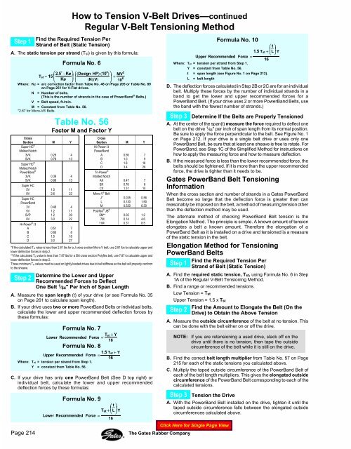
M = Constant from Table No. 56.<br />
*2.67 for Micro-V® <strong>Belt</strong>s.<br />
Cross<br />
Section M Y<br />
Super HC ®<br />
Molded Notch<br />
3VX 0.29 4<br />
5VX 0.78 13<br />
Super HC ®<br />
Molded Notch<br />
PowerBand ®<br />
3VX 0.39 4<br />
5VX 0.98 13<br />
Super HC<br />
5V 1.0 11<br />
8V 2.6 22<br />
Super HC<br />
PowerBand<br />
3V 0.46 4<br />
5V 1.2 11<br />
5VP 1.2 39<br />
8V 3.0 22<br />
Hi-Power ® II<br />
A 0.51 7<br />
B 0.80 8<br />
C 1.5 18<br />
D 3.0 27<br />
Table No. 56<br />
Factor M and Factor Y<br />
Cross<br />
Section M Y<br />
Hi-Power II<br />
PowerBand<br />
A 0.66 7<br />
B 1.0 9<br />
C 1.8 18<br />
D 3.4 28<br />
Tri-Power ®<br />
Molded Notch<br />
AX 0.47 7<br />
BX 0.76 8<br />
CX 1.31 15<br />
Micro-V ® <strong>Belt</strong><br />
J* 0.035 0.56<br />
L 0.130 1.90<br />
M 0.520 6.30<br />
Polyflex ® JB ®<br />
5M** 0.05 1.2<br />
7M 0.14 4.6<br />
11M 0.31 8.5<br />
*If the calculated Tst value is less than 2.81 lbs for a J cross section Micro-V belt, use 2.81 lbs to calculate upper and<br />
lower deflection forces in step 2.<br />
**If the calculated Tst value is less than 7.87 lbs for a 5M cross section Polyflex belt, use 7.87 to calculate upper and<br />
lower deflection forces in step 2.<br />
These minimum T st values must be used on lightly loaded drives due to belt stiffness so the belt will properly conform<br />
to the sheave.<br />
Determine the Lower and Upper<br />
Step 2<br />
Recommended Forces to Deflect<br />
One <strong>Belt</strong> 1 ⁄ 64 " Per Inch of Span Length<br />
A. Measure the span length (t) of your drive (or see Formula No. 35<br />
on Page 261 to calculate span length).<br />
B. If your drive uses two or more PowerBand <strong>Belt</strong>s or individual belts,<br />
calculate the lower and upper recommended deflection forces by<br />
these formulas:<br />
Formula No. 7<br />
Lower Recommended Force = Tst + Y<br />
16<br />
Formula No. 8<br />
Upper Recommended Force =<br />
Where: Tst = tension per strand from Step 1.<br />
Y = constant from Table No. 56.<br />
1.5 Tst + Y<br />
16<br />
C. If your drive has only one PowerBand <strong>Belt</strong> (See D top right) or<br />
individual belt, calculate the lower and upper recommended<br />
deflection forces by these formulas:<br />
Formula No. 9<br />
⎛ t ⎞<br />
T st +<br />
⎜<br />
⎝<br />
L<br />
⎟<br />
⎠ Y<br />
Lower Recommended Force =<br />
16<br />
Formula No. 10<br />
⎛ t ⎞<br />
1.5 T st +<br />
⎜<br />
⎝<br />
L<br />
⎟<br />
⎠ Y<br />
Upper Recommended Force =<br />
16<br />
Where: Tst = tension per strand from Step 1.<br />
Y = constant from Table No. 56.<br />
t = span length (see Figure No. 1 on Page 212).<br />
L = belt length<br />
D. The deflection forces calculated in Step 2B or 2C are for an individual<br />
belt. Multiply these forces by the number of individual strands in a<br />
band to get the lower and upper recommended forces for a<br />
PowerBand <strong>Belt</strong>. (If your drive uses 2 or more PowerBand <strong>Belt</strong>s, use<br />
the band with the fewest number of strands.)<br />
Step 3 Determine If the <strong>Belt</strong>s are Properly Tensioned<br />
A. At the center of the span(t) measure the force required to deflect one<br />
belt on the drive 1 ⁄ 64" per inch of span length from its normal position.<br />
Be sure to apply the force perpendicular to the belt. See Figure No. 1<br />
on Page 212. If your drive is a single belt drive or uses only one<br />
PowerBand <strong>Belt</strong>, be sure that at least one sheave is free to rotate. For<br />
PowerBand, see Step 1C of the Simplified Method for instructions on<br />
how to apply the measuring force and how to measure deflection.<br />
B. If the measured force is less than the lower recommended force, the<br />
belts should be tightened. If it is more than the upper recommended<br />
force, the drive is tighter than it needs to be.<br />
<strong>Gates</strong> PowerBand <strong>Belt</strong> Tensioning<br />
Information<br />
When the cross section and number of strands in a <strong>Gates</strong> PowerBand<br />
<strong>Belt</strong> become so large that the deflection force is greater than can<br />
reasonably be imposed on the belt, a method of measuring tension other<br />
than the deflection method may be used.<br />
The alternate method of checking PowerBand <strong>Belt</strong> tension is the<br />
Elongation Method. The principle is simple. A known amount of tension<br />
elongates a belt a known amount. Therefore the elongation of a<br />
PowerBand <strong>Belt</strong> as it is installed on a drive and tensioned is a measure<br />
of the static tension in the belt.<br />
Elongation Method for Tensioning<br />
PowerBand <strong>Belt</strong>s<br />
Find the Required Tension Per<br />
Step 1<br />
Strand of <strong>Belt</strong> (Static Tension)<br />
A. Find the required static tension, T st, using Formula No. 6 in Step<br />
1A of the Regular V-<strong>Belt</strong> Tensioning Method.<br />
B. Find a range or recommended tensions.<br />
Low Tension = T st<br />
Upper Tension = 1.5 x Tst<br />
Find the Amount to Elongate the <strong>Belt</strong> (On the<br />
Step 2<br />
<strong>Drive</strong>) to Obtain the Above Tension<br />
A. Measure the outside circumference of the belt at no tension. This<br />
can be done with the belt either on or off the drive.<br />
NOTE: If you are retensioning a used drive, slack off on the<br />
drive until there is no tension, then tape the outside<br />
circumference of the belt while it is still on the drive.<br />
B. Find the correct belt length multiplier from Table No. 57 on Page<br />
215 for each of the static tensions you calculated above.<br />
C. Multiply the taped outside circumference of the PowerBand <strong>Belt</strong> of<br />
each of the belt length multipliers. This gives the elongated outside<br />
circumference of the PowerBand <strong>Belt</strong> corresponding to each of the<br />
calculated tensions.<br />
Step 3 Tension the <strong>Drive</strong><br />
A. With the PowerBand <strong>Belt</strong> installed on the drive, tighten it until the<br />
taped outside circumference falls between the elongated outside<br />
circumferences calculated above.<br />
Page 214<br />
The <strong>Gates</strong> Rubber Company