Piezoelectric Ceramics ("PIEZOTITE") Sensors
Piezoelectric Ceramics ("PIEZOTITE") Sensors
Piezoelectric Ceramics ("PIEZOTITE") Sensors

You also want an ePaper? Increase the reach of your titles
YUMPU automatically turns print PDFs into web optimized ePapers that Google loves.
!Note • This !Note PDF catalog • Please is downloaded read rating and from !CAUTION the website (for of Murata storage, Manufacturing operating, rating, co., ltd. soldering, Therefore, mounting it’s specifications and handling) are in subject this catalog to change to prevent or our smoking products and/or in it may burning, be discontinued etc. without advance notice. Please check with our<br />
sales representatives • This catalog or product has only engineers typical specifications before ordering. because there is no space for detailed specifications. Therefore, please approve our product specifications or transact the approval sheet for product specifications before ordering.<br />
• This PDF catalog has only typical specifications because there is no space for detailed specifications. Therefore, please approve our product specifications or transact the approval sheet for product specifications before ordering.<br />
P19E.pdf<br />
08.6.4<br />
2<br />
Characteristics of <strong>Piezoelectric</strong> <strong>Ceramics</strong><br />
2<br />
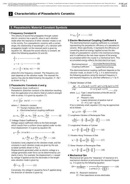
1 Frequency Constant N<br />
The velocity of sound that propagates through a piezoelectric<br />
ceramics has a specific value in each vibration<br />
mode when the resonance of other vibration modes is not<br />
in the vicinity. For a piezoelectric ceramics with a certain<br />
shape, the relationship of wavelength λ of a vibration with<br />
propagation lengthrat the resonant point is given by<br />
equation (4). Because the sound velocity is constant, we<br />
obtain the following equations (5) and (6):<br />
v<br />
fr • r = = N ( HZ • m)<br />
(6)<br />
2<br />
where N is the frequency constant. The frequency constant<br />
depends on the vibration mode. The resonant frequency<br />
may also be determined by the equation, fr = N/r<br />
as shown in Fig. 2.<br />
2 <strong>Piezoelectric</strong> Constants d and g<br />
q <strong>Piezoelectric</strong> Strain Coefficient d<br />
<strong>Piezoelectric</strong> distortion constant is the distortion resulting<br />
from the application of an electric field of uniform strength<br />
with no stress. It is given by equation (7):<br />
where ε T : Dielectric constant<br />
where Y E : Young's modulus (N/m 2 )<br />
where k : Electromechanical coupling coefficient<br />
w Voltage Output Coefficient g<br />
Voltage output coefficient refers to the field strength<br />
which results from a uniform stress applied under no electrical<br />
displacement. It is given by equation (9):<br />
6<br />
2. <strong>Piezoelectric</strong> Material Constant Symbols<br />
λ<br />
= r<br />
2<br />
v = fr • λ<br />
d = k<br />
ε<br />
Y<br />
T<br />
E<br />
(m/V)<br />
(4)<br />
(5)<br />
(7)<br />
T<br />
T<br />
T<br />
ε 33<br />
ε 33<br />
ε 11<br />
d31= k 31 E , d33 = k 33 E , d 15 = k 15 E<br />
(8)<br />
Y 11 Y 33 Y 44<br />
g =<br />
Constants d and g depend on the vibration mode, and the<br />
constants in each vibration mode are given by the subscripted<br />
symbols shown in Fig. 2.<br />
Displacements generated under an electric voltage or a<br />
voltage generated under force can be determined by constants<br />
d and g. For example, the displacement ∆rcaused<br />
by voltage V applied across the electrodes in the lengthwise<br />
vibration mode is given by:<br />
∆r<br />
r<br />
d<br />
T<br />
ε<br />
= d •<br />
31<br />
( V•m/N )<br />
d 31 d 33 d<br />
g =<br />
31 T<br />
g<br />
33 T<br />
g<br />
ε<br />
, =<br />
15<br />
ε<br />
, =<br />
ε<br />
V<br />
t<br />
33<br />
(11)<br />
Conversely, the voltage V caused by force F applied along<br />
the direction of vibration is given by:<br />
33<br />
15<br />
T<br />
11<br />
(9)<br />
(10)<br />
1<br />
V = g •<br />
(12)<br />
31<br />
F<br />
a<br />
3 Electro Mechanical Coupling Coefficient k<br />
The electromechanical coupling coefficient is a constant<br />
representing the piezoelectric efficiency of a piezoelectric<br />
ceramic. More specifically, it represents the efficiency of<br />
converting electrical energy (applied across the electrodes<br />
of a piezoelectric ceramic) into mechanical energy,<br />
and it is defined as the root mean square of the energy<br />
accumulated within the crystal in a mechanical form. This<br />
accumulated energy reflects the total electrical input.<br />
Electromechanical Accumulated Mechanical Energy<br />
=<br />
Coupling Coefficient Supplied Electrical Energy<br />
The electromechanical coupling coefficient depends on the<br />
vibration mode, as shown in Fig. 2. It is determined by<br />
the following equations using the resonant frequency fr,<br />
anti-resonant frequency fa, and their difference ∆ f = fa–fr.<br />
q Radial Vibration of Disk<br />
2<br />
E<br />
kp ( 1 - σ ) J 1{ ψ1 ( 1 + ∆ f / fr) } - ψ1( 1+ ∆ f / fr) J 0{<br />
ψ1(<br />
1+<br />
∆ f / fr)<br />
}<br />
=<br />
2 E<br />
1-kp<br />
( 1 + σ ) J { ψ1<br />
( 1 + ∆ f / fr)<br />
}<br />
(13)<br />
where J 0, J 1 : Type 1 vessel functions of the 0th and 1st<br />
where J 0, J 1 : dimensions<br />
where Jσ E : Poisson's ratio<br />
where Jψ 1 : Lowest dimension of positive root of<br />
where Jψ1 : (1– σ E ) J 1 (ψ) = ψJ 0 (ψ)<br />
If kp is relatively small, equation (13) may be approximated<br />
as follows:<br />
∆f<br />
2<br />
kp ~ 2.529 • (14)<br />
fr<br />
w Lengthwise Vibration of Rectangular Plate<br />
k<br />
1–k<br />
2<br />
31<br />
2<br />
31<br />
π fa π fa<br />
= – • cot •<br />
2 fr 2 fr<br />
e Longitudinal Vibration of Cylinder<br />
2<br />
π fr π fr<br />
k = •<br />
33 cot •<br />
2 fa 2 fa<br />
r Vibration Along Thickness of Disk<br />
2 π fr<br />
k t<br />
= •<br />
2 fa<br />
cot<br />
π fr<br />
•<br />
2 fa<br />
t Shear Vibration of Rectangular Plate<br />
2<br />
π fr π fr<br />
k 15<br />
= •<br />
2 fa<br />
cot •<br />
2 fa<br />
(16)<br />
(17)<br />
(18)<br />
(15)<br />
4 Mechanical Qm<br />
Mechanical Qm gives the "steepness" of resonance of a<br />
mechanical vibration at and around the resonant frequency.<br />
It is given by the following equation:<br />
1<br />
1<br />
Qm = =<br />
2<br />
(19)<br />
π fr R 1C<br />
1<br />
2 πfr<br />
1 fr 2<br />
R 1Cf<br />
{ –<br />
fa<br />
}<br />
where R 1 : Resonant resistance<br />
where Cf : Free capacitance across electrodes