KTH 512
KTH 512
KTH 512

You also want an ePaper? Increase the reach of your titles
YUMPU automatically turns print PDFs into web optimized ePapers that Google loves.
<strong>KTH</strong> <strong>512</strong><br />
CONTROL<br />
CONTROL VALVES / PRESSURE INDEPENDENT BALANCING AND CONTROL VALVES<br />
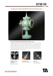
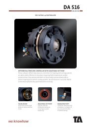
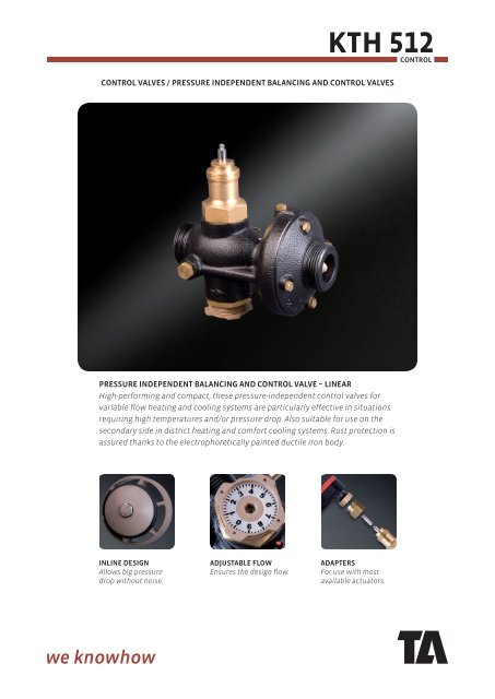
PRESSURE INDEPENDENT BALANCING AND CONTROL VALVE – LINEAR<br />
High-performing and compact, these pressure-independent control valves for<br />
variable flow heating and cooling systems are particularly effective in situations<br />
requiring high temperatures and/or pressure drop. Also suitable for use on the<br />
secondary side in district heating and comfort cooling systems. Rust protection is<br />
assured thanks to the electrophoretically painted ductile iron body.<br />
INLINE DESIGN<br />
Allows big pressure<br />
drop without noise.<br />
ADJUSTABLE FLOW<br />
Ensures the design flow.<br />
ADAPTERS<br />
For use with most<br />
available actuators.
<strong>KTH</strong> <strong>512</strong><br />
CONTROL<br />
TECHNICAL DESCRIPTION<br />
Application:<br />
District heating and cooling systems with variable flow.<br />
Functions:<br />
Differential pressure control over the built-in control valve and flow limitation.<br />
Linear characteristics.<br />
Dimensions:<br />
DN 15-50<br />
Pressure class:<br />
PN 25<br />
Max. differential pressure (ΔpV):<br />
1600 kPa = 16 bar<br />
Pressure drop in the throttle (Fc):<br />
12, 20 and 40 kPa.<br />
Temperature:<br />
Max. working temperature: 140°C<br />
Min. working temperature: -10°C<br />
Media:<br />
Water or neutral fluids, water-glycol mixtures.<br />
Material:<br />
Valve body: Ductile iron EN-GJS-400-18LT<br />
Diaphragms and gaskets: EPDM<br />
Valve plug: EPDM/Stainless steel.<br />
Surface treatment:<br />
Electrophoretic painting.<br />
Marking:<br />
TA, DN, PN, Fc, Kvs, GGG-40.3 and flow direction arrow.<br />
Actuators:<br />
<strong>KTH</strong> <strong>512</strong> can be equipped with adapters for the most<br />
common actuators.<br />
The max. lift of the actuator must be checked.<br />
Max. lift of the control valve:<br />
10 mm<br />
2
<strong>KTH</strong> <strong>512</strong><br />
CONTROL<br />
H1<br />
ØD<br />
TA No DN d D L H1 H2 Kvd q max<br />
[m 3 /h]<br />
Kg<br />
H2<br />
M30x1,5<br />
L<br />
d<br />
Fc = 12 kPa<br />
52 755-120 15/20 R1 78 110 45 98 4,1 0,9 1,5<br />
52 755-125 25/32 R1 1/4 97 150 53 94 16 3,8 2,0<br />
52 755-140 40/50 R2 125 190 66 94 35 7 4,5<br />
Fc = 20 kPa<br />
52 755-020 15/20 R1 78 110 45 98 4,1 1,1 1,5<br />
52 755-025 25/32 R1 1/4 97 150 53 94 16 4,4 2,0<br />
52 755-040 40/50 R2 125 190 66 94 35 10 4,5<br />
Fc = 40 kPa<br />
52 755-220 15/20 R1 78 110 45 98 4,1 1,5 1,5<br />
52 755-225 25/32 R1 1/4 97 150 53 94 16 6,2 2,0<br />
52 755-240 40/50 R2 125 190 66 94 35 13 4,5<br />
→ = Flow direction<br />
Kvd = Is the Kv value of the differential pressure control component when fully open, used to calculate the minimum<br />
pressure drop necessary for the valve to operate according to the formula found under “Sizing”.<br />
ADAPTERS FOR ACTUATORS<br />
TA No<br />
For actuator<br />
52 757-001 Siemens SQS<br />
52 757-002 Johnson Control V7420<br />
52 757-003 Sauter AVM, AVF, SR25, L4<br />
52 757-004 TAC Forta<br />
52 757-005 Hora Mc55<br />
52 757-006 Heimeier EMO-3<br />
52 757-007 Lineg<br />
52 757-008 Danfoss AMV<br />
52 757-009 Belimo NRDVX<br />
52 757-010 Honeywell ML<br />
52 757-011 Samson 5825<br />
52 757-012 Siemens SQX<br />
3
<strong>KTH</strong> <strong>512</strong><br />
CONTROL<br />
CONNECTIONS<br />
With female thread<br />
Threads according to ISO 228<br />
d2<br />
L1<br />
d1<br />
TA No d1 d2 L1*<br />
52 759-015 G1 G1/2 26<br />
52 759-020 G1 G3/4 32<br />
52 759-025 G1 1/4 G1 47<br />
52 759-032 G1 1/4 G1 1/4 52<br />
52 759-040 G2 G1 1/2 52<br />
52 759-050 G2 G2 64,5<br />
With male thread<br />
Threads according to ISO 7<br />
d2<br />
L1<br />
d1<br />
TA No d1 d2 L1*<br />
52 759-115 G1 R1/2 34<br />
52 759-120 G1 R3/4 40<br />
52 759-125 G1 1/4 R1 40<br />
52 759-132 G1 1/4 R1 1/4 45<br />
52 759-140 G2 R1 1/2 45<br />
52 759-150 G2 R2 50<br />
For welding<br />
ØD<br />
L1<br />
d1<br />
TA No d1 D L1*<br />
52 759-315 G1 20,8 37<br />
52 759-320 G1 26,3 42<br />
52 759-325 G1 1/4 33,2 47<br />
52 759-332 G1 1/4 40,9 47<br />
52 759-340 G2 48,0 47<br />
52 759-350 G2 60,0 52<br />
With flange<br />
Flange according to EN-1092-2:1997, type 16.<br />
TA No d1 D L1*<br />
ØD<br />
d1<br />
52 759-515 G1 95 10<br />
52 759-520 G1 105 20<br />
52 759-525 G1 1/4 115 5<br />
52 759-532 G1 1/4 140 15<br />
52 759-540 G2 150 5<br />
52 759-550 G2 165 20<br />
L1<br />
*) Fitting length (from the gasket surface to the end of the connection).<br />
4
<strong>KTH</strong> <strong>512</strong><br />
CONTROL<br />
ACCESSORIES<br />
Measuring point<br />
Max 120°C (Intermittent 150°C)<br />
TA No<br />
L<br />
52 179-009 39<br />
52 179-609 103<br />
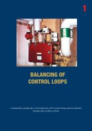
OPERATING FUNCTION<br />
The throttle (2) for flow adjustment, valve for temperature regulation (9) and flow controller (6) are built in series in one<br />
valve body (7). Pressure upstreams of the throttle acts through an internal capillary pipe (V+) to one side of the diaphragm<br />
(8) in the flow regulator.<br />
Pressure downstream of the temperature control valve (9) acts to the other side of the diaphragm together with a spring<br />
force. Pressure drop in the temperature control valve does not exceed 12, 20 or 40 kPa. The accuracy of flow regulation is<br />
practically independent on the pressures upstream and downstream of the controller. As the temperature control valve is<br />
pressure relieved, no additional differential pressure controller is needed and it is possible to use actuators with low force.<br />
V+<br />
1 2<br />
3 4<br />
5<br />
6<br />
1. Fixing nut<br />
2. Throttle<br />
3. Holes for plombing (throttle)<br />
4. Holes for plombing (valve body)<br />
5. Venting screws<br />
6. Flow controller<br />
7. Valve body<br />
8. Diaphragm<br />
9. Control valve<br />
9<br />
8<br />
7<br />
SIZING<br />
1. Select the smallest size for the flow you need according to q max<br />
in the product tables.<br />
2. Check that the available Δp is bigger than the sum of the pressure drops calculated with the formula:<br />
Δp min = Fc + ( 0.01 ) 2 [l/h, kPa]<br />
q<br />
Kvd<br />
5
<strong>KTH</strong> <strong>512</strong><br />
CONTROL<br />
INSTALLATION<br />
Flow direction is shown by the arrow on the valve body. Install the valve so that venting is possible and the flow<br />
adjustment scale is visible. Check allowed positions of the actuator. Installation of a strainer upstream of the valve is<br />
recommended.<br />
When filling, vent the body by using the venting screws.<br />
Instead of the plug R1/4 you can install drain valve or measurement nipple for pressure or temperature measurement.<br />
Application example:<br />
STAD<br />
<strong>KTH</strong> <strong>512</strong><br />
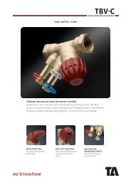
SETTING<br />
Presetting of the maximum flow<br />
Release the fixing nut (1). Turn the throttle (2) clockwise down to the start position of 0,0 turns. Adjust the corresponding<br />
number of scale turns according to flow chart and the pointer (4) on the valve body. Tighten the fixing nut. You can plomb<br />
the flow setting using holes (3a and 3b) on the throttle and the valve body.<br />
a Measure the flow on the balancing valve STAD using the balancing instrument TA-CBI or measuring instrument TA-CMI.<br />
b Adjust the throttle until you measure the required flow on the TA-CBI or TA-CMI.<br />
c Lock the fixing nut. When you lock the nut please hold the throttle in place with an allen key.<br />
Alternative:<br />
a Take the presetting value from the table which is packed with the valve.<br />
b Open the throttle anti-clockwise. The preset value (e.g. 3,4) means that you open the valve three complete turns. After<br />
that turn until the figure 4 fits the red mark on the valve body.<br />
c Lock the fixing nut. When you lock the nut hold the throttle in place with an allen key.<br />
1<br />
3a<br />
2<br />
4<br />
3b<br />
Table - Example:<br />
Position - Presetting<br />
0,0 1,0 2,0 3,0 4,0<br />
,0 57 198 435 656 804<br />
,1 71 222 457 671 815<br />
,2 85 245 479 686 825<br />
,3 99 269 501 700 836<br />
,4 113 293 523 715 846<br />
,5 128 317 546 730 857<br />
,6 142 340 568 745 867<br />
,7 156 364 590 760 878<br />
,8 170 388 612 774 888<br />
,9 184 411 634 789 899<br />
Flow (l/h)<br />
The products, texts, photographs, graphics and diagrams in this brochure may be subject to alteration by Tour & Andersson without prior<br />
notice or reasons being given.<br />
For the most up to date information about our products and specifications, please visit www.tourandersson.com.<br />
6-10-25 <strong>KTH</strong> <strong>512</strong> 2009.04<br />
6