TBV-C - TA Hydronics
TBV-C - TA Hydronics
TBV-C - TA Hydronics

You also want an ePaper? Increase the reach of your titles
YUMPU automatically turns print PDFs into web optimized ePapers that Google loves.
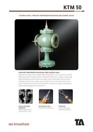
<strong>TBV</strong>-C<br />
ROOM TEMPERATUR CONTROL<br />
ZONE CONTROL / 2-WAY<br />
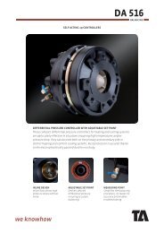
TERMINAL BALANCING VALVE FOR ON-OFF CONTROL<br />
Designed for use in terminal units in heating and cooling systems, the <strong>TBV</strong>-C<br />
ensures accurate hydronic control and optimum throughput over a long lifetime.<br />
<strong>TA</strong>’s dezincification resistant alloy, AME<strong>TA</strong>L ® , minimises the risk of leakage.<br />
PRESETTING TOOL<br />
For accurate and easy<br />
balancing.<br />
SHUT-OFF FUNCTION<br />
Ensures straightforward<br />
maintenance procedures.<br />
SELF-SEALING<br />
MEASURING POINTS<br />
For quick and easy<br />
measurement.
<strong>TBV</strong>-C<br />
ROOM TEMPERATUR CONTROL<br />
Technical description<br />
Application:<br />
Heating and cooling systems.<br />
Functions:<br />
Control<br />
Balancing<br />
Pre-setting<br />
Measuring<br />
Shut-off<br />
Dimensions:<br />
DN 15-20<br />
Pressure class:<br />
PN 16<br />
Temperature:<br />
Max. working temperature: 120°C<br />
Min. working temperature: -20°C<br />
Material:<br />
Valve body: AME<strong>TA</strong>L ®<br />
Seat seal: Valve disc of EPDM<br />
Spindle seal: EPDM O-ring<br />
Valve insert: AME<strong>TA</strong>L ® , PPS (polyphenylsulphide)<br />
Return spring: Stainless steel<br />
Spindle: Teflonized AME<strong>TA</strong>L ®<br />
Smooth ends:<br />
Nipple: AME<strong>TA</strong>L ®<br />
Sealing (DN 25-50): EPDM O-ring<br />
AME<strong>TA</strong>L ® is the dezincification resistant alloy of <strong>TA</strong>.<br />
Marking:<br />
Body: <strong>TA</strong>, PN 16/150, DN, inch size and flow direction arrow.<br />
Identification ring on measuring point.<br />
Actuators:<br />
See separate catalogue leaflet TSE.<br />
2
<strong>TBV</strong>-C<br />
ROOM TEMPERATUR CONTROL<br />
Male thread<br />
L<br />
D<br />
<strong>TA</strong> No DN D Da* L H Kvs Kg<br />
Da<br />
H<br />
<strong>TBV</strong>-C LF, low flow<br />
52 133-015 15 G3/4 M30x1,5 85 58 0,90 0,35<br />
<strong>TBV</strong>-C NF, normal flow<br />
52 134-015 15 G3/4 M30x1,5 85 58 1,8 0,35<br />
52 134-020 20 G1 M30x1,5 96 57 3,4 0,40<br />
Female thread<br />
L<br />
D<br />
<strong>TA</strong> No DN D Da* L H Kvs Kg<br />
Da<br />
H<br />
<strong>TBV</strong>-C LF, low flow<br />
52 133-115 15 G1/2 M30x1,5 81 58 0,90 0,34<br />
<strong>TBV</strong>-C NF, normal flow<br />
52 134-115 15 G1/2 M30x1,5 81 58 1,8 0,34<br />
52 134-120 20 G3/4 M30x1,5 91 57 3,4 0,40<br />
Male thread with eurocone x Female thread<br />
D1<br />
L<br />
D2<br />
<strong>TA</strong> No DN D1 D2 Da* L H Kvs Kg<br />
Da<br />
H<br />
<strong>TBV</strong>-C LF, low flow<br />
52 133-215 15 G3/4 G1/2 M30x1,5 85 58 0,90 0,36<br />
<strong>TBV</strong>-C NF, normal flow<br />
52 134-215 15 G3/4 G1/2 M30x1,5 85 58 1,8 0,35<br />
Kvs = m 3 /h at a pressure drop of 1 bar and fully open valve.<br />
*) Connection to actuator or thermostatic head.<br />
<strong>TBV</strong>-C with female thread can be connected to smooth pipes by KOMBI compression coupling. See catalogue leaflet<br />
KOMBI.<br />
3
<strong>TBV</strong>-C<br />
ROOM TEMPERATUR CONTROL<br />
Male thread with eurocone<br />
L<br />
D<br />
<strong>TA</strong> No DN D Da* L H Kvs Kg<br />
Da<br />
H<br />
<strong>TBV</strong>-C LF, low flow<br />
52 133-315 15 G3/4 M30x1,5 84 58 0,90 0,35<br />
<strong>TBV</strong>-C NF, normal flow<br />
52 134-315 15 G3/4 M30x1,5 84 58 1,8 0,34<br />
Smooth ends<br />
L<br />
ØD<br />
<strong>TA</strong> No DN D Da* L H Kvs Kg<br />
Da<br />
H<br />
<strong>TBV</strong>-C LF, low flow<br />
52 433-115 15 15 M30x1,5 145 58 0,90 0,44<br />
<strong>TBV</strong>-C NF, normal flow<br />
52 434-115 15 15 M30x1,5 145 58 1,8 0,44<br />
52 434-120 20 22 M30x1,5 173 57 3,4 0,57<br />
Female thread x Smooth end<br />
D1<br />
L<br />
ØD2<br />
+<br />
<strong>TA</strong> No DN D1 D2 Da* L H Kvs Kg<br />
Da<br />
H<br />
<strong>TBV</strong>-C LF, low flow<br />
52 435-115 15 G1/2 15 M30x1,5 113 58 0,90 0,39<br />
<strong>TBV</strong>-C NF, normal flow<br />
52 436-115 15 G1/2 15 M30x1,5 113 58 1,8 0,39<br />
52 436-120 20 G3/4 22 M30x1,5 132 57 3,4 0,48<br />
Male thread with eurocone x Smooth end<br />
D1<br />
L<br />
ØD2<br />
<strong>TA</strong> No DN D1 D2 Da* L H Kvs Kg<br />
Da<br />
H<br />
<strong>TBV</strong>-C LF, low flow<br />
52 433-215 15 G3/4 15 M30x1,5 117 58 0,90 0,40<br />
<strong>TBV</strong>-C NF, normal flow<br />
52 434-215 15 G3/4 15 M30x1,5 117 58 1,8 0,40<br />
Kvs = m 3 /h at a pressure drop of 1 bar and fully open valve.<br />
*) Connection to actuator or thermostatic head.<br />
<strong>TBV</strong>-C with female thread can be connected to smooth pipes by KOMBI compression coupling. See catalogue<br />
leaflet KOMBI.<br />
4
<strong>TBV</strong>-C<br />
ROOM TEMPERATUR CONTROL<br />
Connections for male thread<br />
Welding connection<br />
max 120°C<br />
<strong>TA</strong> No Valve DN D For pipe DN<br />
52 009-015 15 G3/4 15<br />
52 009-020 20 G1 20<br />
Soldering connection<br />
max 120°C<br />
<strong>TA</strong> No Valve DN D For pipe Ø<br />
52 009-515 15 G3/4 15<br />
52 009-516 15 G3/4 16<br />
52 009-518 20 G1 18<br />
52 009-522 20 G1 22<br />
Connection with smooth end<br />
For connection with press coupling<br />
max 120°C<br />
<strong>TA</strong> No Valve DN D For pipe Ø<br />
52 009-315 15 G3/4 15<br />
52 009-318 20 G1 18<br />
52 009-322 20 G1 22<br />
Compression connection<br />
max 100°C<br />
D<br />
<strong>TA</strong> No Valve DN D For pipe Ø<br />
53 319-615 15 G3/4 15<br />
53 319-618 15 G3/4 18<br />
53 319-622 15 G3/4 22<br />
53 319-922 20 G1 22<br />
53 319-928 20 G1 28<br />
Support bushes shall be used, for more information see catalogue leaflet FPL.<br />
5
<strong>TBV</strong>-C<br />
ROOM TEMPERATUR CONTROL<br />
Connections for male thread with eurocone<br />
Compression fitting for copper or steel pipes<br />
For eurocone<br />
Metal-to-metal sealing<br />
<strong>TA</strong> No<br />
For pipe Ø<br />
52 136-010 10<br />
52 136-012 12<br />
52 136-014 14<br />
52 136-015 15<br />
52 136-016 16<br />
52 136-018 18<br />
Compression fitting for copper or steel pipes<br />
For eurocone<br />
Nickel plated, soft sealing (EPDM)<br />
Support bushes shall be used, for more information see catalogue leaflet FPL.<br />
<strong>TA</strong> No<br />
For pipe Ø<br />
52 136-112 12<br />
52 136-114 14<br />
52 136-115 15<br />
52 136-116 16<br />
52 136-118 18<br />
Compression fitting for plastic pipes<br />
For eurocone<br />
<strong>TA</strong> No<br />
For pipe Ø<br />
52 136-212 12x2<br />
52 136-214 14x2<br />
52 136-216 16x2<br />
52 136-217 17x2<br />
52 136-218 18x2<br />
52 136-219 18x2,5<br />
52 136-220 20x2<br />
52 136-221 21x2,5<br />
Compression fitting for multi-layer pipes<br />
For eurocone<br />
<strong>TA</strong> No<br />
For pipe Ø<br />
52 136-314 14x2<br />
52 136-316 16x2<br />
52 136-318 18x2<br />
6
<strong>TBV</strong>-C<br />
ROOM TEMPERATUR CONTROL<br />
Accessories<br />
Presetting tool <strong>TBV</strong>-C<br />
<strong>TA</strong> No<br />
52 133-100<br />
Setting<br />
<strong>TBV</strong>-C is delivered with a red protective cap, <strong>TA</strong> No 52 143-100, which<br />
must be used when isolating the valve.<br />
<strong>TBV</strong>-C is delivered with the pre-setting fully open. Setting of a valve<br />
for a given pressure drop, e.g. corresponding to position 5 is done<br />
as follows:<br />
1. Place the presetting tool, <strong>TA</strong> No 52 133-100, at the valve.<br />
2. Turn the presetting tool so that position 5 is pointing at the<br />
index* of the valve body.<br />
3. Remove the presetting tool. The valve is now set.<br />
*)<br />
There is a diagram for every valve size that shows the flow for different<br />
pressure drops and settings.<br />
Noise<br />
The following conditions must be fulfilled in order to avoid noise in the heating system:<br />
• Flows correctly balanced<br />
• The water in the system must have been de-aerated<br />
• Circulation pumps which do not give too high differential pressure (alternative use a differential pressure controller,<br />
e.g. S<strong>TA</strong>P).<br />
The maximum recommended pressure drop in order to aviod noise: 30 kPa = 0,3 bar.<br />
7
<strong>TBV</strong>-C<br />
ROOM TEMPERATUR CONTROL<br />
Measuring accuracy<br />
Flow deviation at different settings<br />
± % 20<br />
18<br />
16<br />
14<br />
12<br />
10<br />
8<br />
6<br />
4<br />
2<br />
0<br />
1 2 3 4 5 6 7 8 9 10 *)<br />
*) Position<br />
Try to avoid mounting taps and pumps, immediately before the valve.<br />
2D<br />
5D<br />
2D<br />
10D<br />
Sizing<br />
When Dp and the design flow are known, use the formula to calculate the Kv-value.<br />
8
<strong>TBV</strong>-C<br />
ROOM TEMPERATUR CONTROL<br />
Application example<br />
*)<br />
C<br />
<strong>TBV</strong>-C<br />
*) Shut-off valve<br />
When the valve is mounted with the actuator downwards, and there is a risk of condensation, an actuator with protection<br />
class IP 34, or higher, is needed.<br />
Closing force<br />
Necessary force (F) to close the valve vs the differential pressure (Dp).<br />
600<br />
DN 15<br />
500<br />
400<br />
DN 20<br />
∆ p [kPa]<br />
300<br />
200<br />
100<br />
90 100 110 120 130 140 150<br />
F [N]<br />
9
<strong>TBV</strong>-C<br />
ROOM TEMPERATUR CONTROL<br />
Diagram <strong>TBV</strong>-C LF, DN 15<br />
Position<br />
kPa<br />
60<br />
50<br />
1 2 3 4 5 6 7 8 9 10<br />
40<br />
30<br />
20<br />
15<br />
10<br />
7.5<br />
5<br />
4<br />
3<br />
2<br />
1.5<br />
1<br />
5 8 10 15 20 30 40 50 75 100 150 200 300 500 750 1000<br />
l/h<br />
Position 1 2 3 4 5 6 7 8 9 10<br />
Kv 0,05 0,15 0,22 0,26 0,31 0,41 0,53 0,68 0,74 0,90<br />
Recommended area: Pos. 3-10<br />
10
<strong>TBV</strong>-C<br />
ROOM TEMPERATUR CONTROL<br />
Diagram <strong>TBV</strong>-C NF, DN 15<br />
kPa 60<br />
Position<br />
1 2 3 4 5 6 7 8 9 10<br />
50<br />
40<br />
30<br />
20<br />
10<br />
7.5<br />
5<br />
4<br />
3<br />
2<br />
1.5<br />
1<br />
10<br />
20 30 40 50 75 100 200 300 500 1000 2000<br />
l/h<br />
Position 1 2 3 4 5 6 7 8 9 10<br />
Kv 0,22 0,33 0,45 0,50 0,60 0,82 0,99 1,11 1,43 1,80<br />
Recommended area: Pos. 3-10<br />
11
<strong>TBV</strong>-C<br />
ROOM TEMPERATUR CONTROL<br />
Diagram <strong>TBV</strong>-C NF, DN 20<br />
Position<br />
kPa<br />
60<br />
50<br />
1 2 3 4 5 6 7 8 9 10<br />
40<br />
30<br />
20<br />
15<br />
10<br />
7.5<br />
5<br />
4<br />
3<br />
2<br />
1.5<br />
1<br />
20 30 40 50 75 100 150 200 300 500 750 1000<br />
2000<br />
4000<br />
l/h<br />
Position 1 2 3 4 5 6 7 8 9 10<br />
Kv 0,40 0,53 0,67 0,82 1,03 1,29 1,72 2,40 2,96 3,40<br />
Recommended area: Pos. 3-10<br />
Tour & Andersson retains the right to make changes to its products and specifications without prior notice.<br />
5-5-25 <strong>TBV</strong>-C 2008.05<br />
12