52989 M12 Laser class 2 - Banner Engineering
52989 M12 Laser class 2 - Banner Engineering
52989 M12 Laser class 2 - Banner Engineering

Create successful ePaper yourself
Turn your PDF publications into a flip-book with our unique Google optimized e-Paper software.
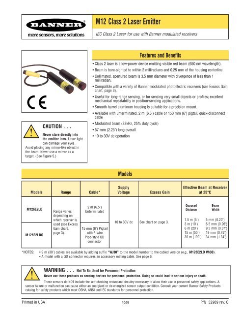
<strong>M12</strong> Class 2 <strong>Laser</strong> Emitter<br />
IEC Class 2 <strong>Laser</strong> for use with <strong>Banner</strong> modulated receivers<br />
CAUTION . . .<br />
Never stare directly into<br />
the emitter lens. <strong>Laser</strong> light<br />
can damage your eyes.<br />
Avoid placing any mirror-like object in<br />
the beam. Never use a mirror as a<br />
target. (See Figure 5.)<br />
Features and Benefits<br />
• Class 2 laser is a low-power device emitting visible red beam (650 nm wavelength).<br />
• Beam is bore-sighted to within 2 milliradians and 0.25 mm of the housing centerline.<br />
• Collimated, apertured beam is 3.5 mm diameter with divergence of less than 1<br />
milliradian.<br />
• Compatible with a variety of <strong>Banner</strong> modulated photoelectric receivers (see Excess Gain<br />
chart, page 3).<br />
• Useful for long-range sensing, or for sensing very small objects or profiles; excellent<br />
mechanical repeatability in position-sensing applications.<br />
• Smooth-barrel aluminum housing is suitable for a precision mount.<br />
• Available with unterminated, 2 m (6.5') cable or 150 mm (6") pigtail, quick-disconnect<br />
cable<br />
• Modulated beam (33kHz, 25% duty cycle)<br />
• 57 mm (2.25") long overall<br />
• 10 to 30V dc operation<br />
Models<br />
Models Range Cable*<br />
Supply<br />
Voltage<br />
Excess Gain<br />
Effective Beam at Receiver<br />
at 25°C<br />
<strong>M12</strong>6E2LD<br />
<strong>M12</strong>6E2LDQ<br />
Range varies,<br />
depending on<br />
which receiver is<br />
used (see Excess<br />
Gain chart,<br />
page 3).<br />
2 m (6.5')<br />
Unterminated<br />
15 mm (6") Pigtail<br />
with 3-wire<br />
Pico-style QD<br />
connector<br />
10 to 30V dc See chart on page 3.<br />
Opposed<br />
Distance<br />
Beam<br />
Width<br />
1.5 m (5') 5 mm (0.20")<br />
3 m (10') 6.5 mm (0.26")<br />
6 m (20') 9.5 mm (0.37")<br />
15 m (50') 19 mm (0.75")<br />
30 m (100') 34 mm (1.34")<br />
*NOTES:<br />
• 9 m (30') cables are available by adding suffix “W/30” to the model number to the cabled version (e.g., <strong>M12</strong>6E2LD W/30).<br />
• A model with a QD connector requires an accessory mating cable. See page 6.<br />
WARNING . . . Not To Be Used for Personnel Protection<br />
Never use these products as sensing devices for personnel protection. Doing so could lead to serious injury or death.<br />
These sensors do NOT include the self-checking redundant circuitry necessary to allow their use in personnel safety applications. A<br />
sensor failure or malfunction can cause either an energized or de-energized sensor output condition. Consult your current <strong>Banner</strong> Safety Products<br />
catalog for safety products which meet OSHA, ANSI and IEC standards for personnel protection.<br />
Printed in USA 10/03 P/N <strong>52989</strong> rev. C
<strong>M12</strong> Class 2 <strong>Laser</strong> Emitter<br />
<strong>M12</strong> Class 2 <strong>Laser</strong> Emitter Specifications<br />
Supply Voltage and Current<br />
Supply Protection Circuitry<br />
Delay at Power-up<br />
Sensing Beam<br />
Beam Diameter at Aperture<br />
Beam Divergence<br />
Beam Placement<br />
<strong>Laser</strong> Control<br />
Indicators<br />
Construction<br />
Environmental Rating<br />
Connections<br />
Operating Temperature<br />
<strong>Laser</strong> Classification<br />
Certifications<br />
10 to 30V dc (10% maximum ripple) at less than 30 mA<br />
Protected against electrostatic discharge (ESD) and transient voltages;<br />
Protected against reverse polarity<br />
Less than 30 milliseconds<br />
650 nm visible red Class 2 laser (temperature coefficient 0.2 nm/°C);<br />
Pulse Width: 7µs<br />
Rep Rate: 30µs<br />
Peak Output Power: 2.8 milliwatts<br />
Approximately 3.5 mm (0.14") diameter<br />
±0.5 milliradians typical at 25°C; ±1.0 milliradian at operating temperature extremes<br />
Within 0.25 mm (0.01") and ±2 milliradians of mechanical centerline axis of housing<br />
Apply +10 to 30V dc to black wire to enable beam; Inhibit beam by applying 0V dc or by opening circuit<br />
Enable delay less than 30 milliseconds; Inhibit delay less than 1 millisecond<br />
Indicators are visible through rear cover.<br />
Green indicates power applied<br />
Yellow indicates laser enabled<br />
12.7 mm (0.50") diameter smooth aluminum barrel; Black hard-coat anodized finish, MIL-A-8625 Type III, Class II<br />
NEMA 6; IEC IP67<br />
PVC-jacketed 3-conductor 2 m (6.5') or 9 m ( 30') high-flex cable (unterminated); or<br />
150 mm (6") pigtail with 3-wire Pico-style connector<br />
Temperature: 0° to 40° C (32° to 104° F); Maximum relative humidity: 90% at 50° C (non-condensing)<br />
Class 2 laser product; complies to 21 CFR 1040.10, EN 60825-1:2001 except for deviations pursuant to<br />
laser notice 50, dated 7-26-01<br />
2 P/N <strong>52989</strong> rev. C<br />
<strong>Banner</strong> <strong>Engineering</strong> Corp. • Minneapolis, MN U.S.A.<br />
www.bannerengineering.com • Tel: 763.544.3164
<strong>M12</strong> Class 2 <strong>Laser</strong> Emitter<br />
<strong>M12</strong> Dimensions<br />
Aperture/Caution Label<br />
(Do not clamp only in this area)<br />
See "Connections"<br />
in Specifications<br />
Green LED<br />
Indicates power applied<br />
LASER RADIA<br />
DO NOT ST<br />
INTO BEA<br />
Peak Power: 2.2mW, 66<br />
33kHz 25% duty cycle<br />
Yellow LED<br />
Indicates laser enabled<br />
ø12.7 mm<br />
(0.50")<br />
57 mm<br />
(2.25")<br />
Excess Gain<br />
Excess Gain of the <strong>M12</strong> emitter is dependent on the particular receiver used.<br />
Following is a comparison of the excess gain for various recommended receivers at<br />
15 m (50').<br />
Receiver<br />
Excess Gain<br />
at 15 m (50')<br />
MULTI-BEAM<br />
SBRX1 19,000<br />
SBR1 19,000<br />
SBRXD1 19,000<br />
SBRD1 19,000<br />
MAXI-BEAM<br />
RSBR 14,000<br />
RSBRSR 1,500<br />
VALU-BEAM<br />
SMW95R 34,000<br />
SMI91RQD 18,000<br />
EZ-BEAM<br />
T18SN6R 7,500<br />
T30SN6R 7,500<br />
S12SN6R 7,500<br />
Receiver<br />
Excess Gain<br />
at 15 m (50')<br />
MINI-BEAM<br />
SM31R 2,500<br />
SM31RL 17,000<br />
SM31RMHS 1,800<br />
SM31RLMHS 11,000<br />
ECONO-BEAM<br />
SE61R<br />
SE61RMHS<br />
600<br />
500<br />
Others<br />
SM51RB<br />
Q23SN6R<br />
1,200<br />
400<br />
Q10AN6R 250<br />
Q45BB6R 9,000<br />
For information on compatibility of the <strong>M12</strong> emitter with other <strong>Banner</strong> photoelectric<br />
receivers contact the factory Applications Group at the address or numbers listed on<br />
the back cover.<br />
<strong>Banner</strong> <strong>Engineering</strong> Corp. • Minneapolis, MN U.S.A.<br />
www.bannerengineering.com • Tel: 763.544.3164<br />
P/N <strong>52989</strong> rev. C 3
<strong>M12</strong> Class 2 <strong>Laser</strong> Emitter<br />
Mounting<br />
Mounting suggestions:<br />
• To take advantage of the bore-sight beam placement offered by<br />
the <strong>M12</strong> laser emitter, use a two-part clamp mount or a<br />
mounting block with a precision-drilled hole. Allow minimum<br />
clearance for the 12.7 mm (0.50") diameter housing, max. dia.<br />
12.83 mm (0.505").<br />
• Clamp on both sides of the label. Do not clamp only on the<br />
labeled area. Use only plastic-tipped screws or set screws —<br />
not metal — to avoid compression of the housing.<br />
Mounting bracket, assembly SMB46X3, is available, and is<br />
recommended for use with the <strong>M12</strong> (see Figure 1 and ordering<br />
information on page 7). It consists of:<br />
• A black-anodized aluminum block with holes drilled for<br />
mounting in any of 3 directions and plastic set screws, and<br />
• An adjustable stainless steel bracket with 3 spring-loaded<br />
screws (2 of which are used for precise alignment).<br />
The mounting block may be ordered separately, (model SMB127;<br />
see pages 6 and 7).<br />
To mount the <strong>M12</strong>, insert the laser emitter into the black mounting<br />
block, through any of the three holes. Check to be sure that the<br />
label area of the emitter is not aligned with a set screw, then tighten<br />
the set screws (using the supplied 3/64" Allen wrench) so the<br />
emitter is held snugly in place. Then mount the block to the<br />
adjustable baseplate (or to your own bracket). Mount the bracket<br />
base using your own M5 or #10 screws or bolts, and then check<br />
for alignment (see page 5). Tighten or loosen one or two of the<br />
precision alignment screws (using the supplied 2 mm Allen<br />
wrench) until the laser is accurately aligned.<br />
Figure 1. Model SMB127 mounting block<br />
Figure 1a. Mounting bracket model SMB46X3, front and rear views<br />
Figure 2. Three possible <strong>M12</strong> orientations<br />
4 P/N <strong>52989</strong> rev. C<br />
<strong>Banner</strong> <strong>Engineering</strong> Corp. • Minneapolis, MN U.S.A.<br />
www.bannerengineering.com • Tel: 763.544.3164
<strong>M12</strong> Class 2 <strong>Laser</strong> Emitter<br />
<strong>Laser</strong> Emitter<br />
W = 2 mm + 2X(tan.0029°) = 2 mm + X(0.001)<br />
Figure 4.<br />
Opposed Distance (X)<br />
<strong>Laser</strong> Emitter<br />
Y = X(tan Ø)<br />
Approx. 2 mm<br />
Approx.<br />
0.5mrad = 0.029°<br />
Ø = Misalignment Angle<br />
Sensing Distance = X<br />
Beam Width (W)<br />
1.5 m (5') 5.0 mm (0.20")<br />
3 m (10') 6.5 mm (0.26")<br />
6 m (20') 9.5 mm (0.37")<br />
15 m (50') 19 mm (0.75")<br />
30 m (100') 34 mm (1.34")<br />
Figure 3. <strong>M12</strong> laser emitter beam divergence at 25°C<br />
(beam size vs. distance)<br />
Figure 5.<br />
Y<br />
Sensing Distance = X<br />
Opposed Distance (X)<br />
Beam Displacement (Y)<br />
for 1° of Misalignment<br />
1.5 m (5') 25 mm (1")<br />
3 m (10') 50 mm (2")<br />
6 m (20') 100 mm (4")<br />
15 m (50') 250 mm (10")<br />
30 m (100') 500 mm (20")<br />
Beam displacement per degree of misalignment<br />
<strong>M12</strong><br />
Target<br />
Receiver<br />
;; @@ <br />
;; @@ <br />
;; @@ <br />
At long distances, use retroreflective tape to locate the<br />
beam at the receiver location. Never use a mirror as an<br />
alignment target.<br />
W<br />
Alignment<br />
Conventional modulated infrared LED photoelectric emitters are<br />
designed with beam divergence angles of several degrees. As a<br />
result, most emitters are easily aligned to their receivers by<br />
simple line-of-sight methods.<br />
In sharp contrast to conventional photoelectric emitters,<br />
<strong>M12</strong> laser emitters have a beam divergence of only 0.03°<br />
(0.5 milliradians) at 25° C (77°F) ambient temperature (see<br />
Figure 3). This translates, for example, to a beam diameter of<br />
only 0.37" at a distance of 20'. Consequently, there is very little<br />
forgiveness for angular misalignment.<br />
The beam size listed in Figure 3 is also the effective beam size<br />
at the receiver. The effective beam is equal to the minimum<br />
opaque object profile required to block the light beam. The<br />
beam size at the emitter is 3.5 mm (0.14") diameter.<br />
The effect of angular misalignment is dramatic (see Figure 4).<br />
The wide beam angles offered by conventional photoelectric<br />
emitters allow several degrees of misalignment between the<br />
optical axes of the emitter and receiver. This is not true for<br />
laser emitters which require their beam center to directly strike<br />
the receiver lens. Figure 4 shows how far the laser beam will<br />
miss the center of the receiver lens for each degree of angular<br />
misalignment (in any plane). Note that even at only a 5' range,<br />
one degree of misalignment will cause the laser beam to miss<br />
the lens of most receivers.<br />
Alignment Tip: The visible red beam of the laser emitter is<br />
easily seen in subdued lighting. At opposed distances of up to<br />
10', attach a sheet of white paper directly in front of the<br />
receiver lens. Mark the location of the lens center on the paper.<br />
This mark is used as an aiming target. Sight along the beam<br />
from directly behind the laser emitter. Adjust the emitter<br />
mounting until the red image (the dot of red light) is centered<br />
exactly on the mark. Remove the paper and check the response<br />
of the receiver.<br />
For longer distances (up to 25'), replace the white paper with a<br />
4" x 4" square of high-grade retroreflective tape (<strong>Banner</strong> model<br />
BRT-THG-4X4-5 or equivalent; see Figure 5). For greater<br />
distances, use a larger sheet of retroreflective material (see<br />
page 7).<br />
<strong>M12</strong>6E2LD<br />
bu -<br />
10-30 VDC<br />
bn +<br />
bk LASER<br />
(+ON, -OFF)<br />
Pulse Power< 2.8 mW, 650-670 nm, 33 kHz, 7 µS Pulse. Complies with 21 CFR 1040.10<br />
and EN60825-1:2001 except for deviations pursuant to laser notice No. 50, dated 7-26-01<br />
LASER LIGHT - DO NOT STARE INTO BEAM CLASS 2 LASER PRODUCT<br />
<strong>Banner</strong> <strong>Engineering</strong> Corp. • Minneapolis, MN U.S.A.<br />
www.bannerengineering.com • Tel: 763.544.3164<br />
P/N <strong>52989</strong> rev. C 5
<strong>M12</strong> Class 2 <strong>Laser</strong> Emitter<br />
Hookups<br />
<strong>M12</strong>6E2LD <strong>Laser</strong> Diode Emitter<br />
Unterminated Cable<br />
<strong>M12</strong>6E2LDQ <strong>Laser</strong> Diode Emitter<br />
3-pin Pico-style Connector<br />
bk<br />
bn<br />
bu<br />
<strong>Laser</strong> beam<br />
enable<br />
+<br />
10-30V dc<br />
-<br />
bk<br />
bn<br />
bu<br />
<strong>Laser</strong> beam<br />
enable<br />
+<br />
10-30V dc<br />
-<br />
Mounting Brackets<br />
SMB46X3<br />
Bracket<br />
Assembly<br />
• Assembly with mounting block and<br />
adjustable bracket<br />
• Includes: 2mm Shortarm hex key<br />
3/64" Shortarm hex key<br />
4 Set screws<br />
SMB127<br />
Mounting<br />
Block<br />
• Mounting block only<br />
• Includes: 3/64" Shortarm hex key<br />
4 Set screws<br />
2x 7.1 mm<br />
(0.28")<br />
2x 11.4 mm<br />
(0.45")<br />
12.9 mm<br />
(0.508")<br />
36 mm<br />
(1.4")<br />
10.6 mm<br />
(0.42")<br />
21.1 mm<br />
(0.83")<br />
31.8 mm<br />
(1.25")<br />
14.0 mm<br />
(0.55")<br />
8x M5 or #10 clearance<br />
ø6.6mm<br />
(0.26")<br />
ø30.5mm<br />
(1.20")<br />
64.5 mm<br />
(2.54")<br />
60°<br />
60°<br />
10.6 mm<br />
(0.42 ")<br />
12.9 mm<br />
(0.508")<br />
17.8 mm<br />
(0.70")<br />
2x M3<br />
or #4 Clearance<br />
26.9 mm<br />
(1.06")<br />
23.6 mm<br />
(0.93")<br />
22.9 mm<br />
(0.90")<br />
13.5 mm<br />
(0.53") 6.4 mm<br />
(0.25")<br />
5.1 mm<br />
(0.20")<br />
18.5 mm<br />
(0.73")<br />
21.6 mm<br />
(0.85")<br />
12.9 mm<br />
(0.508")<br />
21.6 mm<br />
(0.85")<br />
3x #4-40 Thru<br />
36 mm<br />
(1.4")<br />
17.8 mm<br />
(0.70")<br />
61 mm to 64 mm<br />
(2.4" to 2.5")<br />
61.0 mm<br />
(2.40")<br />
6 P/N <strong>52989</strong> rev. C<br />
<strong>Banner</strong> <strong>Engineering</strong> Corp. • Minneapolis, MN U.S.A.<br />
www.bannerengineering.com • Tel: 763.544.3164
<strong>M12</strong> Class 2 <strong>Laser</strong> Emitter<br />
Retroreflective Tape<br />
Model<br />
Reflectivity<br />
Factor<br />
Maximum<br />
Temperature<br />
Size<br />
Unit<br />
BRT-THG-4X4-5<br />
BRT-THG-8.5X11-2<br />
BRT-THG-18X36<br />
0.7<br />
0.7<br />
0.7<br />
60°C (140°F)<br />
60°C (140°F)<br />
60°C (140°F)<br />
100 x 100 mm (4" x 4")<br />
216 x 280 mm (8.5" x 11")<br />
457 x 914 mm (18" x 36")<br />
Package of 5<br />
Package of 2<br />
Single Sheet<br />
Pico-Style Quick-Disconnect Cables<br />
Cable: PUR jacket, polyurethane connector body, POM snap-lock coupling<br />
Conductors: 26 or 24 AWG high-flex stranded, gold-plated contacts<br />
Temperature: -40° to +90°C (-40° to +194°F)<br />
Voltage Rating: 30V ac/36V dc<br />
Environmental Rating: None<br />
Model<br />
Style Length Dimensions Pin-out<br />
PKG3-2<br />
3-Pin<br />
Straight<br />
2 m (6.5')<br />
28 mm max.<br />
(1.1")<br />
ø10 mm max.<br />
(0.4")<br />
Black Wire<br />
Blue Wire<br />
Brown Wire<br />
<strong>Banner</strong> <strong>Engineering</strong> Corp. • Minneapolis, MN U.S.A.<br />
www.bannerengineering.com • Tel: 763.544.3164<br />
P/N <strong>52989</strong> rev. C 7
<strong>M12</strong> Class 2 <strong>Laser</strong> Emitter<br />
WARRANTY: <strong>Banner</strong> <strong>Engineering</strong> Corp. warrants its products to be free from defects for one year. <strong>Banner</strong> <strong>Engineering</strong> Corp. will repair or<br />
replace, free of charge, any product of its manufacture found to be defective at the time it is returned to the factory during the warranty<br />
period. This warranty does not cover damage or liability for the improper application of <strong>Banner</strong> products. This warranty is in lieu of any<br />
other warranty either expressed or implied.<br />
P/N <strong>52989</strong> rev. C<br />
<strong>Banner</strong> <strong>Engineering</strong> Corp., 9714 Tenth Ave. No., Minneapolis, MN 55441 • Phone: 763.544.3164 • www.bannerengineering.com • Email: sensors@bannerengineering.com