
You also want an ePaper? Increase the reach of your titles
YUMPU automatically turns print PDFs into web optimized ePapers that Google loves.
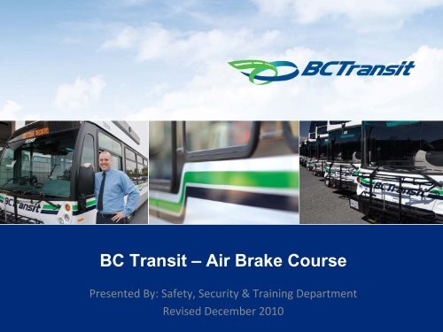
<strong>BC</strong> <strong>Transit</strong> – <strong>Air</strong> <strong>Brake</strong> <strong>Course</strong><br />
Presented By: Safety, Security & Training Department<br />
Revised December 2010<br />
1
<strong>BC</strong> <strong>Transit</strong> – <strong>Air</strong> <strong>Brake</strong> <strong>Course</strong><br />
Learning Objectives:<br />
1. <strong>Air</strong> <strong>Brake</strong>s Introduction<br />
2. Definitions & Concepts<br />
3. Five Main Components<br />
4. Basic <strong>Air</strong> <strong>Brake</strong> System<br />
5. Other <strong>Air</strong> <strong>Brake</strong> System Components<br />
6. Single Circuit<br />
7. Dual Circuit<br />
8. Trailers<br />
9. Off‐Highway Units<br />
10. Summary, Questions, Wrap‐Up<br />
2
<strong>BC</strong> <strong>Transit</strong> – <strong>Air</strong> <strong>Brake</strong> <strong>Course</strong><br />
1. <strong>Air</strong> <strong>Brake</strong>s Introduction:<br />
a) Resources<br />
b) Homework<br />
c) Quizzes<br />
d) IC<strong>BC</strong> <strong>Air</strong> <strong>Brake</strong> Theory Exam<br />
e) <strong>Air</strong> <strong>Brake</strong> Endorsement<br />
3
<strong>BC</strong> <strong>Transit</strong> – <strong>Air</strong> <strong>Brake</strong> <strong>Course</strong><br />
1. <strong>Air</strong> <strong>Brake</strong>s Introduction:<br />
a) Resources<br />
• IC<strong>BC</strong> Driving Commercial Vehicles Guide<br />
(Chapters 1, 2, 8, 9 & 10 –see page 2)<br />
• Richmond Public Library Practice Test<br />
http://www.yourlibrary.ca/driving/<br />
• <strong>BC</strong> <strong>Transit</strong> Website<br />
(Being developed –see <strong>BC</strong> <strong>Transit</strong> –<strong>Air</strong> <strong>Brake</strong> <strong>Course</strong> Handout in<br />
Interim)<br />
4
<strong>BC</strong> <strong>Transit</strong> – <strong>Air</strong> <strong>Brake</strong> <strong>Course</strong><br />
1. <strong>Air</strong> <strong>Brake</strong>s Introduction:<br />
b) Homework<br />
• Day 1: Chapter 1 & 2 (Read & Questions), plus Chapter 8 (Read)<br />
• Day 2: Chapter 8 (Questions), Chapter 9 & 10 (Read & Questions)<br />
c) Quizzes<br />
• Day 1: <strong>Air</strong> <strong>Brake</strong> <strong>Course</strong> ‐ Chapters 1 & 2 –Review<br />
• Day 2: <strong>Air</strong> <strong>Brake</strong> <strong>Course</strong> –Final Exam<br />
5
<strong>BC</strong> <strong>Transit</strong> – <strong>Air</strong> <strong>Brake</strong> <strong>Course</strong><br />
1. <strong>Air</strong> <strong>Brake</strong>s Introduction:<br />
d) IC<strong>BC</strong> <strong>Air</strong> <strong>Brake</strong> Theory Exam<br />
• Cost is $15<br />
• Letter of Verification required (bring this to IC<strong>BC</strong> on exam day)<br />
• Multiple Choice Exam technique (read each question twice thoroughly,<br />
only answer if completely clear –otherwise skip question)<br />
e) <strong>Air</strong> <strong>Brake</strong> Endorsement<br />
• After successfully completing the IC<strong>BC</strong> <strong>Air</strong> <strong>Brake</strong> Theory Exam, a<br />
practical evaluation will need to be completed (this is performed during<br />
the IC<strong>BC</strong> Road Test & Pre‐Trip –must be completed within 1 year of<br />
completion of Theory Exam, or Theory Exam would have to be redone)<br />
6
<strong>BC</strong> <strong>Transit</strong> – <strong>Air</strong> <strong>Brake</strong> <strong>Course</strong><br />
2. Definitions & Concepts:<br />
a) Traction, Heat, Friction<br />
b) Weight & Speed – Stopping Distance<br />
c) Force Multiplication<br />
d) Compressed <strong>Air</strong><br />
e) Combining Compressed <strong>Air</strong> with Force Multiplication<br />
7
<strong>BC</strong> <strong>Transit</strong> – <strong>Air</strong> <strong>Brake</strong> <strong>Course</strong><br />
2. Definitions & Concepts:<br />
a) Traction, Heat, Friction<br />
8
The final factor that will determine<br />
if a vehicle will move is traction.<br />
The final factor that will determine if<br />
a vehicle will stop is traction.<br />
Traction: the ability of a tire to grip the road surface over which it rolls.<br />
Friction: force that resists movement between two surfaces in contact with<br />
each other.<br />
The engine of this truck converts the energy of heat<br />
into the energy of motion. The brakes of this truck<br />
must convert the energy of motion into the energy<br />
of heat. The friction between the the brake linings<br />
and drums generate heat while reducing the<br />
mechanical energy of the revolving drums and<br />
wheels. This energy is absorbed by the drums and<br />
dissipated as heat to the atmosphere.<br />
9
<strong>BC</strong> <strong>Transit</strong> – <strong>Air</strong> <strong>Brake</strong> <strong>Course</strong><br />
2. Definitions & Concepts:<br />
b) Weight & Speed – Stopping Distance<br />
10
Weight - Speed - Distance<br />
When weight is doubled, the braking power to stop in the same<br />
distance, must double!<br />
When speed is doubled, the braking power required to<br />
stop in the same distance must increase 4 times!<br />
When weight and speed are doubled, the braking power<br />
to stop in the same distance must increase 8 times!<br />
A vehicle carrying a load of 14,000 kgs at 16 km/h is brought to a stop in 30 meters<br />
under normal braking. If this vehicle’s weight increased to 28,000 kgs., and the<br />
speed was increased to 32 km/h, it would require 8 times the braking power to stop<br />
in the same 30 meter distance. Remember, this is under ideal conditions. If traction<br />
were reduced by poor road conditions, what effect would this have on overall<br />
stopping distance?<br />
11
Stopping Distance<br />
Stopping distance consists of four factors...<br />
1) Perception Time: (also described as see-think time) = the time it<br />
takes the brain to recognize a hazard. Usually 3/4 second or 13 meters travel.<br />
2) Reaction time: (also described as Do Time) = it is the time required<br />
for your brain to tell your foot to apply the brakes. Usually 3/4 of a second<br />
or 13 meters travelled.<br />
3) <strong>Brake</strong> Lag: the time required for air to travel through a properly<br />
maintained air brake system and actually begin applying the brakes.<br />
Usually 4/10 of a second.<br />
4) Braking Distance: the time or distance a vehicle travels before<br />
it stops after the brakes have been applied.<br />
12
Perception Time (See-Think)<br />
Perception Time, generally, is 3/4<br />
second. This is the time it takes for us to<br />
perceive that there might be a need to<br />
stop or take some other defensive action.<br />
At 50 km/h, your vehicle will travel 13<br />
meters (or one bus length) before your<br />
brain even decides it would be a good<br />
idea to do something about the hazard.<br />
What types of techniques can you think of<br />
that would help us reduce or compensate<br />
for this 3/4 second delay?<br />
13
Reaction Time (Do)<br />
Reaction time, also generally about 3/4<br />
second. This is the time it takes for us to<br />
react to a need to stop or take some other<br />
defensive action. Again, at 50 km/h,<br />
your vehicle will travel 13 meters (or<br />
one bus length) over the road before<br />
the brakes even begin to stop the<br />
vehicle. Here is where defensive driving<br />
techniques can make for a whole lot less<br />
accidents.<br />
14
4/10 sec.<br />
<strong>Brake</strong> Lag<br />
(mechanical lag)<br />
<strong>Brake</strong> lag is usually 4/10<br />
second, in a properly<br />
maintained system. It<br />
doesn’t sound like much, but<br />
consider once again at 50<br />
km/h your vehicle will<br />
travel nearly 10 meters<br />
before the brake linings<br />
come into contact with the<br />
drums.<br />
15
Braking Distance<br />
This distance is dependent on many<br />
factors. The condition of the brake<br />
components, brake adjustment,<br />
road, operator, speed and load of the<br />
vehicle will all determine how much<br />
asphalt disappears under your bumper<br />
before coming to a stop.The<br />
professional driver realizes the<br />
limitations of his/her vehicle’s<br />
brakes and adjusts their driving<br />
accordingly.<br />
16
Stopping Distance…(total stopping time)<br />
•is the total distance travelled before your vehicle stops after factoring in<br />
perception time, reaction time, brake lag time and braking distance.<br />
• Other factors such as poor road condition due to inclement weather, driver<br />
fatigue and vehicle condition will add length to overall stopping distance.<br />
•As a professional driver, it is incumbent upon you to prepare yourself for any<br />
eventuality and govern your driving habits accordingly.<br />
•Techniques such as brake coverage, eye lead time, effective scanning and<br />
comprehensive vehicle pre-trip inspections can do a lot to even the odds.<br />
• Your passengers, other road users and your own safety depend on your attitude.<br />
Think professional, act professional and professional you will be! b<br />
17
RoadSense Tip<br />
•Total Stopping Time will be even longer if brakes are incorrectly y adjust or<br />
vehicle is on a downgrade.<br />
•The most common air brake system defect found during a commercial l vehicle<br />
inspection is brakes that are out of adjustment.<br />
18
<strong>BC</strong> <strong>Transit</strong> – <strong>Air</strong> <strong>Brake</strong> <strong>Course</strong><br />
2. Definitions & Concepts:<br />
c) Force Multiplication<br />
19
Force Multiplication (Mechanical Advantage)<br />
100<br />
4 1<br />
A<br />
C<br />
B<br />
400<br />
“…give me a lever long enough and a place to rest it, and I will lift the world…”<br />
Braking systems use devices to gain a mechanical advantage. The<br />
most common device for this purpose is leverage. In this simple<br />
example, a lever is placed on a pivot called a fulcrum. The distance<br />
from A to C is 4 feet, and the distance from C to B is 1 foot. Therefore<br />
the ratio is 4:1. If a 100 lb. downward force is exerted against point A,<br />
an upward force of 400 lbs. is achieved at point B.<br />
20
Apply the principal from the previous slide to the example below:<br />
C<br />
A<br />
D<br />
B<br />
“A” represents the slack adjuster in<br />
the foundation brakes. As pressure is<br />
applied, the slack adjuster works as a<br />
lever, on shaft “D.” As the “S”cam<br />
attached to the shaft rotates, a<br />
mechanical advantage is achieved at<br />
points “B” and “C”. If the slack<br />
adjuster were 6 inches in length, and<br />
the “S” cams were 1 inch in length,<br />
the ratio would be 6:1.<br />
21
<strong>BC</strong> <strong>Transit</strong> – <strong>Air</strong> <strong>Brake</strong> <strong>Course</strong><br />
2. Definitions & Concepts:<br />
d) Compressed <strong>Air</strong><br />
22
Using Compressed <strong>Air</strong> to Our Advantage...<br />
Atmospheric Pressure<br />
15 lbs./sq. in.<br />
Suppose the walls of the room you are sitting in now, were to begin to squeeze<br />
together evenly in all directions. Assume the room is sealed and no air can escape.<br />
• What would happen to the atmospheric pressure as the size of the room began to<br />
shrink?<br />
•Would the pressure in the room begin to increase?<br />
•Would the rate of increase be proportional to the reduction in the size of the room?<br />
•What would the pressure be like in the “red” room?<br />
23
Compressed air is air that has been forced into a space<br />
smaller than it would normally occupy.<br />
Rather than squeezing the room smaller, suppose we instead forced air into a<br />
chamber or container...<br />
As the compressor pumps air (forces air into the<br />
cylinder), the pressure within the cylinder<br />
(reservoir) begins to increase. That pressure is<br />
exerted against all the surfaces of the reservoir at<br />
the same time, and at the same pressure.This<br />
compressed air can then be used to mechanical<br />
advantage in the operation of the vehicles brakes.<br />
24
<strong>BC</strong> <strong>Transit</strong> – <strong>Air</strong> <strong>Brake</strong> <strong>Course</strong><br />
2. Definitions & Concepts:<br />
e) Combining Compressed <strong>Air</strong> with Force Multiplication<br />
25
Obtaining the mechanical advantage...<br />
The reservoir below, contains compressed air at 10 pounds per square<br />
inch (psi). (atmospheric pressure is considered to be 0.)<br />
0 5 10 25 30 35 40<br />
1 inch dia.<br />
made in<br />
Canada<br />
pounds per sq. in.<br />
If a constant supply of compressed air were directed through a pipe one inch<br />
in diameter, and a one inch plug were placed in the pipe, the compressed air<br />
would push against the plug. Holding a scale against the plug would register<br />
how many pounds of force were being exerted against the plug.<br />
26
Combining mechanical advantage to achieve force multiplication.<br />
<strong>Air</strong><br />
pressure<br />
at 100 psi.<br />
3000 lbs<br />
of force<br />
Slack adjuster - 6 ins. in length<br />
100 psi<br />
<strong>Brake</strong> chamber - 30 sq. in. diameter<br />
18,000 ft.-lbs.<br />
of force<br />
here!<br />
“S” cam<br />
1 inch in<br />
length<br />
100 psi is exerted against a diaphragm 30 sq. ins. in area inside the brake chamber<br />
pictured here. 30 X 100 = 3000 lbs. of force! Times that by the length of the slack<br />
adjuster (lever) and the total force is… 18,000 ft-lbs. of force.<br />
27
<strong>BC</strong> <strong>Transit</strong> – <strong>Air</strong> <strong>Brake</strong> <strong>Course</strong><br />
2. Definitions & Concepts:<br />
• Putting It All Together<br />
• Review<br />
28
As the driver applies the brake pedal, the brake linings are forced against the inside<br />
surface of the brake drum. The spinning wheel produces friction as the linings make<br />
contact. This friction causes heat which is then dissipated to the atmosphere. The<br />
amount of heat the drums can absorb, depends on the thickness of the metal. If the<br />
drums are “turned” or worn too thin, they will be unable to absorb the heat produced<br />
by braking, and brake fade will occur.<br />
If one set of<br />
brakes was<br />
poorly<br />
adjusted, the<br />
rest of the<br />
brakes would<br />
have to absorb<br />
more heat<br />
energy than<br />
they were<br />
initially<br />
designed for.<br />
Speed is critical<br />
when descending a<br />
steep grade. To<br />
avoid overtaxing<br />
the brakes, follow<br />
this simple rule:<br />
Never descend a<br />
hill at a speed<br />
greater than the<br />
vehicle is capable<br />
of climbing the hill.<br />
29
Review of Section Two<br />
In this section we have studied the concepts of:<br />
•Heat, Energy, Traction and Friction<br />
•Speed, Weight and Distance<br />
•How we obtain a Mechanical Advantage to achieve Force<br />
Multiplication<br />
•Compressing air, and combining this with Force Multiplication<br />
•Looked at Stopping Distance and how it can be effected by adverse<br />
conditions.<br />
The next section will begin our exploration of the components of the<br />
air brake system.<br />
Let’s Review...<br />
30
Review Questions: Section 1<br />
1) What is the final factor that will determine if a vehicle will<br />
move?<br />
2) What is the final factor that will determine if a vehicle will stop?<br />
3) How is the heat dissipated that is generated by the brakes?<br />
4) If one set of brakes were poorly adjusted, what effect would this<br />
have on the remaining sets of brakes?<br />
5) What is meant by the term friction?<br />
6) What are the four components of stopping distance?<br />
7) If the weight of your vehicle were doubled, how many times<br />
must the braking power be increased in order to stop in the same<br />
distance? If speed doubles? If both weight and speed were<br />
doubled?<br />
8) <strong>Brake</strong>s stop the vehicle. Is this true or false?<br />
4)…the 5)…the 8)… False. force other 6)…perception 3)…by Traction resisting brakes the 7)…two determines would brake movement 1) time, Traction 2) drums times; have Traction reaction if to between to four the do the vehicle’s time; more times; atmosphere two brake than eight surfaces brakes their lag; times share will in contact be of effective. braking<br />
braking distance<br />
Left click for answers<br />
31
<strong>BC</strong> <strong>Transit</strong> – <strong>Air</strong> <strong>Brake</strong> <strong>Course</strong><br />
3. Five Main Components:<br />
a) Compressor & Governor<br />
b) <strong>Air</strong> Lines<br />
c) Reservoirs<br />
d) Foot Valve<br />
e) Foundation <strong>Brake</strong>s<br />
32
<strong>BC</strong> <strong>Transit</strong> – <strong>Air</strong> <strong>Brake</strong> <strong>Course</strong><br />
3. Five Main Components:<br />
a) Compressor & Governor<br />
33
The Compressor & Governor<br />
The compressor has two adjacent pistons attached to it’s crankshaft which is in<br />
is in constant drive with the engine. When the compressor is “loaded” or<br />
pumping, air is forced through the main discharge line to the reservoirs. As<br />
pressure builds to one of two main standard operating pressures (85 - 105 or 115<br />
115 - 135) the unloading device in the top of the compressor, holds the inlet<br />
valves open and air is pumped between the pistons, allowing the compressor to<br />
compressor to cool. This is the “unloaded” stage. The compressor is controlled<br />
controlled by the governor which is usually mounted to the side of the<br />
compressor. A typical “two-flow” compressor is pictured here.<br />
We need to know...<br />
• The compressor output can be effected by a dirty air filter, loose belts, or worn rings.<br />
• It is usually lubricated by the engine lubrication system. (some have their own)<br />
•During the pre-trip inspection, the compressor is checked visually before engine start-up,<br />
start-up, for belt condition and tension, mounting security, and evidence of oil leaks.<br />
•During the pre-trip inspection, the compressor output is checked. It must be able to pump<br />
pump from 50 to 90 psi. in 3 minutes or less.<br />
34
The Governor<br />
The governor may be considered to be the brain of the air brake<br />
system. It tells the compressor when to load and unload based on<br />
the amount of air pressure in the reservoirs. Two standard main<br />
reservoir operating pressures are:<br />
•85 psi. to 105 psi. and 115 psi to 135 psi.<br />
•Some systems operate at 85 psi. to 135 psi.<br />
•The spread between loading and unloading pressures must<br />
not be less than 20 psi.<br />
•During the pre-trip inspection, the cut-in (load) and cut-out<br />
(unload) pressures of the governor are checked.<br />
…next slide<br />
35
The Governor<br />
(continued)<br />
(1) <strong>Air</strong> flowing from the compressor moves down the main discharge line to the wet tank.<br />
(2) From the wet tank, it passes through a one-way check valve to the dry tank<br />
(3) Reservoir pressure arrives at the governor, “telling” it the pressure in the dry tank<br />
(4) When sufficient pressure is developed, the governor signals the compressor to unload.<br />
4<br />
3<br />
1<br />
2<br />
36
One-way Check Valve<br />
The one-way check valve is situated between the wet tank and the dry tank.<br />
This is the first defence against a catastrophic air loss. If the main discharge line<br />
ruptured or the wet tank were punctured, the one-way check valve will not<br />
allow the air pressure to flow backwards out of the dry tank.<br />
When draining the reservoirs, always open the drain valve of the wet tank first.<br />
If there is still pressure in the dry tank, you know the one-way check valve<br />
worked.<br />
The check valve is a common valve in the air brake system and is used at many<br />
other locations and for different applications.<br />
37
<strong>BC</strong> <strong>Transit</strong> – <strong>Air</strong> <strong>Brake</strong> <strong>Course</strong><br />
3. Five Main Components:<br />
b) <strong>Air</strong> Lines<br />
38
<strong>Air</strong> Lines<br />
• <strong>Air</strong> lines link compressed air from one component to another.<br />
• <strong>Air</strong> flowing from the Compressor moves down the <strong>Air</strong> Line or main<br />
discharge line to the wet tank.<br />
• <strong>Air</strong> lines are made of a durable, tensile material – they can withstand<br />
pressure of at least 150 PSI.<br />
• Application air lines (also known as service or control lines) have a<br />
narrow diameter – Supply air lines (also known as delivery lines) have a<br />
larger diameter.<br />
39
<strong>BC</strong> <strong>Transit</strong> – <strong>Air</strong> <strong>Brake</strong> <strong>Course</strong><br />
3. Basic Components:<br />
c) Reservoirs (<strong>Air</strong> Tanks)<br />
40
Safety Valve<br />
The Reservoirs<br />
One-way<br />
check valve<br />
Low air warning device<br />
Wet tank<br />
Dry Tank<br />
Drain Valve<br />
Drain Valve<br />
The reservoirs, or tanks, are made of steel and serve to contain the compressed air delivered<br />
by the compressor. <strong>Air</strong> from the compressor is hot. When it comes into contact with the cold<br />
steel, condensation occurs. This moisture must not be allowed to accumulate in the tanks. If it<br />
did, it would reduce the amount of air the tank would be able to hold, and thus, reduce the<br />
volume of air available for the operation of the vehicles brakes. A safety valve is fitted to allow<br />
the air to escape if over-pressurisation occurs. (140 to 150 psi.) A one way check valve between<br />
the reservoirs disallows the back flow of air from the dry tank to the wet tank. A low air<br />
warning device will warn the operator of low air pressure when the pressure in the reservoirs<br />
drops to 60 psi. This warning is either audible or visual.<br />
We need to know<br />
We need to know…more reservoirs, more volume; they must be drained at least once per day;<br />
they must be drained completely in order to allow all the moisture and sludge to escape; the<br />
wet tank should be drained first so the function of the one-way check valve can be tested.<br />
41
Low <strong>Air</strong> Warning Device & Safety Valve<br />
The low air warning device is a simple spring loaded electrical switch that triggers a<br />
warning in the driver’s compartment. This device must activate before the reservoir air<br />
pressure drops to 60 psi. The warning can be either audible or visual. This device is<br />
checked during the pre-trip inspection. Some systems, usually trucking applications,<br />
use a “wig-wag” This is a metal flag that drops from above the driver’s windshield into<br />
his/her line of sight.<br />
The safety valve is fitted to the wet tank. Its purpose is to release excess pressure should<br />
the governor fail to unload the compressor due to a governor failure or a problem with the<br />
unloader mechanism in the compressor head. The safety valve should release when<br />
pressure reaches 140 to 150 psi.<br />
Low air warn.<br />
safety valve<br />
“Wig-Wag”<br />
42
<strong>Air</strong> Gauges<br />
60<br />
50<br />
40<br />
70<br />
80<br />
85<br />
90<br />
100<br />
105<br />
30<br />
110<br />
115<br />
20<br />
120<br />
10 135 bye-bye<br />
<strong>Air</strong> gauges come in many shapes and sizes, but they<br />
all have one thing in common. Information.<br />
A reservoir gauge will advise of the amount of air<br />
present in the tank(s) at any given time. It is used<br />
during pre-trip inspections to determine:<br />
•governor cut-in and cut-out pressures<br />
•low air warning device function (above 60 psi.)<br />
•at what pressure the spring brakes apply<br />
automatically.<br />
•pressure drop when a full foot valve application<br />
is made to test for brake adjustment.<br />
•check for air leaks (maximum 3 psi./min. loss<br />
single units – buses or tractors, 4 psi./min.<br />
tractor & trailer, 6 psi./min. tractor & tandem<br />
trailer)<br />
•an application gauge will tell you how much air<br />
is being delivered to the brake chambers.<br />
43
<strong>Air</strong> Gauges<br />
NOTE: Gauges on<br />
Double Decker and<br />
Dart read in KPA<br />
with a scale from<br />
0 - 11.<br />
Operating range is<br />
outside of the red bar<br />
44
<strong>BC</strong> <strong>Transit</strong> – <strong>Air</strong> <strong>Brake</strong> <strong>Course</strong><br />
3. Five Main Components:<br />
d) Foot Valve<br />
45
The Foot Valve<br />
Two typical foot valves are pictured here. The uppermost one is used<br />
primarily in buses. The lower example is suspended from the firewall and is<br />
used mostly in trucking applications. They operate in precisely the same<br />
way, being spring loaded and self-balancing.<br />
We need to know...<br />
•The foot valve is considered to be the most important valve in the system,<br />
because without it, we could not control brake application pressure.<br />
•It is a self-balancing device, meaning that even if a small leak occurred in the<br />
system during a brake application, the foot valve would regulate the application<br />
air such that the brakes would remain applied.<br />
•The foot valve is spring loaded, so the operator feels only the spring pressure,<br />
not the pressure of the brake application, as in a hydraulic brake system.<br />
•Maximum brake application pressure available at any time is only that which<br />
is present in the system’s reservoirs. Application pressure cannot exceed<br />
reservoir pressure.<br />
46
The Foot Valve<br />
The foot valve controls application pressure.<br />
•Reservoir air is available at the base of the foot valve. (dark green)<br />
•Application air, as demanded by the operator, is delivered to the brake<br />
chambers. (light green and light red)<br />
•The further down the operator depresses the treadle, the more air<br />
pressure is delivered to the brake chambers.<br />
•When the treadle is released, the brake application is released.<br />
Front<br />
Application air<br />
Application air<br />
Rear<br />
Reservoir air<br />
47
<strong>BC</strong> <strong>Transit</strong> – <strong>Air</strong> <strong>Brake</strong> <strong>Course</strong><br />
3. Five Main Components:<br />
e) Foundation <strong>Brake</strong>s (<strong>Brake</strong> Chambers, Slack Adjusters, <strong>Brake</strong> Linings &<br />
<strong>Brake</strong> Drums)<br />
48
The Foundation <strong>Brake</strong>s: <strong>Brake</strong> Chamber, Slack Adjusters,<br />
and <strong>Brake</strong> Linings /Drums<br />
A brake chamber is a circular container divided in the middle by<br />
a flexible diaphragm. <strong>Air</strong> pressure pushing against the<br />
diaphragm causes it to move away from the pressure, forcing the<br />
push rod outward against the slack adjuster. The force exerted<br />
by this motion depends on air pressure and diaphragm size.<br />
The Slack Adjuster has two functions in the operation of the<br />
vehicle's brakes. First, it converts the pushing motion of the push<br />
rod into a twisting motion at the “S” cam. Second, as the name<br />
suggests, the slack adjuster provides a means of reducing “free<br />
play” or slack in the foundation brake linkages.<br />
49
Two Types of Slack Adjusters<br />
There are two types of slack adjusters currently<br />
in use with drum type brakes:<br />
manual adjustment<br />
automatic slack adjustment<br />
Manual adjustment must be<br />
made every day at the start<br />
of the shift. If conditions<br />
warrant, adjustment may be<br />
required more often.<br />
Pre-Trip Inspection:<br />
•Set up brakes before the start of each day’s<br />
shift.<br />
•Maximum push rod travel under a full foot<br />
valve application must not exceed 1 3/4<br />
inches.<br />
•Maximum push rod travel under pry bar<br />
pull must not exceed 3/4 of an inch.<br />
•When making a full foot valve application<br />
with engine off and park brake released, look<br />
for any large drops in air pressure as<br />
indicated on the pressure gauge.<br />
Automatic slack adjusters can<br />
be adjusted by simply making a<br />
full brake application with the<br />
foot valve. Upon release of the<br />
foot valve, the slack adjuster<br />
will automatically adjust your<br />
brakes to optimum push rod<br />
travel.<br />
50
Automatic Slack Adjusters<br />
Pre-Trip Inspection:<br />
•Set up brakes before the start of each day’s shift.<br />
•Maximum push rod travel with a type 30 brake chamber under a full foot<br />
valve application must not exceed 2 inches - using the pry bar method, there<br />
should be no more than ¾of an inch of push rod travel.<br />
•When making a full foot valve application with engine off and park brake<br />
released, look for any large drops in air pressure as indicated on the<br />
pressure gauge.<br />
51
Automatic Slack Adjusters<br />
Automatic Slack Adjusters With Hexagonal Adjusting Bolts:<br />
•If the slack adjuster has a hexagonal adjusting bolt, the<br />
brakes are adjusted by turning the adjusting bolt in a<br />
clockwise direction until the lining contacts the drum.<br />
•Baking off the adjusting bolt by 1/2 turn should restore<br />
running clearance (backing off may take considerable force<br />
and a ratcheting sound and feel will occur – this is normal).<br />
Automatic Slack Adjusters With Square Adjusting Bolts:<br />
•If the slack adjuster has a square adjusting bolt located at the bottom end of the<br />
body, do not attempt adjusting until a spring-loaded pawl that meshes with<br />
internal teeth is disengaged.<br />
•If the slack adjuster has a square adjusting bolt, the brakes are adjusted by<br />
turning the adjusting bolt in a counter-clockwise direction until the lining<br />
contacts the drum.<br />
•Baking off the adjusting bolt by 1/2 turn should restore running clearance.<br />
•Release the button or re-install the spring and pawl if they were removed.<br />
52
<strong>Brake</strong> Chambers and Slack Adjusters<br />
As the linings wear, the distance<br />
between the linings and the drums<br />
begins to enlarge.<br />
If this condition were to deteriorate,<br />
braking could be lost completely!<br />
Loss of brake adjustment is the<br />
leading cause of brake failure in the<br />
transportation industry!<br />
53
<strong>Brake</strong> Linings and Drums (or Rotors)<br />
The assembly pictured to the left, is the<br />
foundation brake. It is composed of the brake<br />
drum, linings, shoes, “S” cam, slack adjuster,<br />
push rod, and brake chamber.<br />
•The drum dissipates the heat generated by the<br />
brakes.<br />
•The linings are made of composite material and<br />
wear according to use. (load, speed, frequency of<br />
braking)<br />
•The distance between the lining and the drum<br />
when the brake is released will become larger as<br />
the linings wear.<br />
•The slack adjuster provides a means of<br />
reducing this distance.<br />
Remember…<br />
The most common cause of brake failure in the commercial transportation rtation industry, is<br />
lack of proper adjustment! Always check brake adjustment, or set up your brakes,<br />
during your initial pre-trip inspection.<br />
54
<strong>BC</strong> <strong>Transit</strong> – <strong>Air</strong> <strong>Brake</strong> <strong>Course</strong><br />
3. Five Main Components:<br />
• Review<br />
55
Review of Section Three<br />
In this section we learned…<br />
The 5 main components of the air brake system…<br />
•Compressor to pump air, with a governor to control the compressor<br />
•<strong>Air</strong> Lines to allow the pressurized air to flow between the brake system<br />
components<br />
•Reservoirs to store the compressed air<br />
•Foot Valve (usually called a brake pedal ) to apply the brakes by directing<br />
compressed air from the reservoir to the brakes<br />
•Foundation brakes, including brake chambers, slack adjusters, brake linings<br />
and drums or rotors, to transfer the force generated by the compressed air through<br />
mechanical linkage to apply the brakes<br />
We know the purpose of each of these components within the air brake system, and we<br />
achieved a basic understanding of how each one works.<br />
In the next section we will begin to put these components together to build a basic<br />
system.<br />
Let’s review...<br />
56
Review Questions: Section Three<br />
1) What are the five main components of the air brake system?<br />
2) How is a plugged air filter likely to effect the compressor?<br />
3) What causes moisture to form in the air brake system?<br />
4) When is the compressor able to accomplish most of its cooling?<br />
5) How often must reservoirs be drained?<br />
6) What is the maximum air pressure available for a brake application at any given time?<br />
7) Is it necessary to allow all the air to escape from the reservoirs? Why?<br />
8) What would result if the brake drums were allowed to wear thin?<br />
9) What are two functions of a slack adjuster?<br />
10) How does the amount of slack effect the operation of the brakes?<br />
11) What is the maximum allowable push rod travel under<br />
a full brake application? With a pry bar?<br />
12) What is the most common cause of loss of effective braking on air brake equipped<br />
vehicles?<br />
13) What causes brake fade at high brake temperatures?<br />
13)<br />
7)Yes. Otherwise the sludge 1) 2) restrict compressor/governor; will 8) they not 6) 11) air run would that 10) flow one 4) out which increased during and overheat because reducing three is the present air brake the resulting quarter unloaded lines; compressor air lag under reservoirs; the inches; time; stage<br />
loss pressure output possible three of foot braking quarters will valve; complete push foundation of it an loss to inch the sides brakes<br />
9) 5) 3)<br />
drums of effective braking<br />
convert daily condensation<br />
worn<br />
or a more<br />
thin<br />
pushing often<br />
or turned 12) brakes out of adjustment<br />
motion if conditions<br />
to far<br />
to a twisting warrant motion; allow a means of adjusting the brakes<br />
Left click for answers<br />
57
<strong>BC</strong> <strong>Transit</strong> – <strong>Air</strong> <strong>Brake</strong> <strong>Course</strong><br />
4. Basic <strong>Air</strong> <strong>Brake</strong> System:<br />
a) Review How 5 Main Components Work Together<br />
b) Quick Release Valve Function<br />
c) Relay Valve Function<br />
d) Park <strong>Brake</strong> System<br />
Please note: the piping diagrams that follow, do not accurately represent the actual<br />
valves and components in an air brake system. Our purpose is to provide you with<br />
a basic, theoretical understanding of air brake systems sufficient for you to obtain<br />
an air brake endorsement on your license, and perform a pre-trip inspection so as<br />
to diagnose problems in the system before going on the road.<br />
58
<strong>BC</strong> <strong>Transit</strong> – <strong>Air</strong> <strong>Brake</strong> <strong>Course</strong><br />
4. Basic <strong>Air</strong> <strong>Brake</strong> System:<br />
a) Review How 5 Main Components Work Together<br />
59
No. 1<br />
COMPRESSOR: pumps air; 50 to 90 psi. in less than 3 minutes; lubricated by engine oil;<br />
belt driven (some have their own lubrication and drive system); has an air filter, that if<br />
plugged, would reduce efficiency.<br />
Left click for answer<br />
60
No. 2<br />
GOVERNOR: tells compressor when to load and unload (85-<br />
105 or 115 to 135 psi.)<br />
Left click for answer<br />
61
No. 3<br />
FOOT VALVE: most important valve in the system; spring loaded<br />
and self balancing; has a different feel from hydraulic brakes<br />
Left click for answer<br />
62
No. 4<br />
AIR LINES: link air from one component to another.<br />
RESERVOIRS: contain compressed air; must be drained daily and completely; more<br />
than one reservoir to provide a greater volume of air.<br />
Left click for answer<br />
63
No. 10<br />
BRAKE DRUM: absorbs and dissipates heat generated by braking.<br />
Left click for answer<br />
64
No. 11<br />
BRAKE SHOES AND LININGS: shoes contain linings; linings make contact with inside<br />
surface of brake drum, creating friction required to provide braking.<br />
Left click for answer<br />
65
No. 12<br />
“S” CAM: forces shoes and linings against drum<br />
Left click for answer<br />
66
No. 13<br />
SLACK ADJUSTER: provides a means of reducing the distance between<br />
linings and drums (slack); converts pushing motion into twisting motion<br />
Left click for answer<br />
67
No. 14<br />
PUSH ROD: transmits force from brake chamber; must not move more than 1<br />
3/4 inches under full application test: 3/4 inch under pry bar pull<br />
Left click for answer<br />
68
No. 15<br />
BRAKE CHAMBER: part of force multiplication process; drives push rod<br />
Left click for answer<br />
69
<strong>BC</strong> <strong>Transit</strong> – <strong>Air</strong> <strong>Brake</strong> <strong>Course</strong><br />
4. Basic <strong>Air</strong> <strong>Brake</strong> System:<br />
b) Quick Release Valve Function<br />
70
Quick Release Valve and Stop Light Switch<br />
The Quick Release Valve, situated on the front axle, provides<br />
a quicker release of the front brakes by allowing the air to<br />
exhaust at the centre point between the brake chambers. The<br />
Stop Light Switch can be activated with as little as 4 psi<br />
brake application pressure.<br />
Quick release valve<br />
Stop Light Switch<br />
71
<strong>BC</strong> <strong>Transit</strong> – <strong>Air</strong> <strong>Brake</strong> <strong>Course</strong><br />
4. Basic <strong>Air</strong> <strong>Brake</strong> System:<br />
c) Relay Valve Function<br />
72
The Relay Valve<br />
The relay valve provides quicker application and release of the<br />
rear brakes.<br />
The relay valve function is used in other applications within the<br />
air brake system, which will be explored later.<br />
In order to understand the need for this valve, let’s look again at<br />
brake lag time… next slide<br />
73
<strong>Brake</strong> Lag Time<br />
...is the time it takes for air to travel through a properly maintained system.<br />
high volume - slow moving<br />
low volume - fast moving<br />
•Lag time is dependent, however, on the inside diameter of the brake line through<br />
which the air is travelling.<br />
• In the two examples pictured here, the air will travel faster through the smaller<br />
diameter line and slower through the larger diameter line.<br />
• However, the larger diameter line is capable of delivering a much greater volume of<br />
air, as opposed to the smaller line which delivers a much smaller volume of air.<br />
Click for animation (once for each pipe)<br />
74
In this diagram, the dark green line is a LARGER diameter than the bright<br />
green line. The dark green line delivers reservoir air to the foot valve AND to<br />
the relay valve at the rear axle. When a brake application is made, the foot<br />
valve delivers the requested amount of air to the relay valve, through the<br />
bright green line, known as a “control line.”<br />
The air delivered by the foot valve “dead-ends” at the relay valve. This causes<br />
the relay valve to “open” and it delivers the requested amount of application<br />
air from its own supply of reservoir air.<br />
...next slide<br />
Control line<br />
Reservoir air<br />
75
Relay Valve Operation<br />
Control line from foot valve<br />
<strong>Air</strong> dead ends here!<br />
To rear brake chambers<br />
Application air from the<br />
foot valve arrives at the top<br />
of the relay valve, via the<br />
control line (bright green.)<br />
It contacts a diaphragm<br />
inside the relay valve, and<br />
dead ends there.<br />
This opens the relay valve<br />
internally, and air from the<br />
reservoir is metered to the<br />
brake chambers.<br />
From Reservoir<br />
...next slide<br />
76
• Because the relay valve accesses the<br />
reservoir air directly, and the application air<br />
acts only as a control device, the brake lag<br />
that would normally occur between the foot<br />
valve and the rear brakes, is greatly reduced.<br />
• This concept of “relaying” a brake<br />
application is used in other valves in the<br />
system, so it’s important to confirm your<br />
understanding at this point.<br />
77
• If the relay valve were not installed in the<br />
system, the front brakes would be applying<br />
before the rear brakes. (The foot valve is closer<br />
to the front brakes, than the rear brakes.)<br />
• Since most braking is accomplished by the<br />
rear brakes of a long wheel base vehicle, this<br />
would not be a desirable situation.<br />
78
<strong>BC</strong> <strong>Transit</strong> – <strong>Air</strong> <strong>Brake</strong> <strong>Course</strong><br />
4. Basic <strong>Air</strong> <strong>Brake</strong> System:<br />
d) Park <strong>Brake</strong> System<br />
79
Section - Parking <strong>Brake</strong>s<br />
By the end of this section the student will understand:<br />
• How a park brake works.<br />
• Why a spring brake is a reliable type of park brake.<br />
• How to release different types of park brakes when<br />
the air system cannot supply sufficient pressure for<br />
release.<br />
80
A spring type park brake serves three important functions:<br />
•Its primary function is to provide a reliable means of<br />
securing an air brake equipped vehicle. (parking brake)<br />
•It can serve as an emergency brake if an air loss<br />
occurred during vehicle operation.<br />
•It can be used in place of the air operated primary<br />
service brakes in a dual air equipped vehicle. (We will<br />
study dual air systems later in the air brake course.)<br />
81
The park brake control<br />
valve, located in the<br />
driver’s compartment, is<br />
standardised throughout<br />
the commercial transport<br />
industry.<br />
The valve knob will<br />
always be diamond<br />
shaped and yellow in<br />
colour.<br />
82
However, some valves<br />
may be designed to be<br />
pushed to apply the<br />
brake, while others may<br />
be designed to be pulled<br />
out to apply the brake.<br />
Buses usually incorporate<br />
the first type where the<br />
valve is pushed to apply<br />
the park brake.<br />
83
The Parts of the Spring Type Parking <strong>Brake</strong><br />
Push Rod<br />
Service brake<br />
chamber<br />
Service brake<br />
diaphragm<br />
Spring brake<br />
diaphragm<br />
Spring brake<br />
chamber<br />
Park brake<br />
actuating spring<br />
Access for<br />
caging bolt<br />
Slack Adjuster<br />
Note: on “Maxibrake”<br />
type park<br />
brakes there is no<br />
access for caging.<br />
An emergency<br />
release reservoir<br />
is provided<br />
instead.<br />
Return springs<br />
84
Park <strong>Brake</strong> and Service <strong>Brake</strong> Released<br />
Service brake is released (no air<br />
present in service brake chamber)<br />
System air pressure is present<br />
in spring brake chamber.<br />
The park brake spring is<br />
held compressed by the<br />
system air pressure. The<br />
park brake is released,<br />
but ready for emergency<br />
braking if required.<br />
85
Park <strong>Brake</strong> Released - Service <strong>Brake</strong> Application<br />
System air is still<br />
present in the park<br />
brake chamber. The<br />
park brake spring is<br />
compressed so the park<br />
brake is released.<br />
Application air, as delivered by the foot valve, is present in<br />
the service brake chamber. The service brakes are applied.<br />
86
Park <strong>Brake</strong> Applied - Service <strong>Brake</strong> Released (no compounding)<br />
No air in service<br />
brake chamber<br />
No system air pressure in<br />
park brake chamber<br />
The park brake spring<br />
has expanded, pushing<br />
against the push rod,<br />
which has moved the<br />
slack adjuster away from<br />
the brake chamber, and<br />
the brakes are applied.<br />
87
Mechanical Release of the Park <strong>Brake</strong> (Caging the Spring)<br />
On “piggy-back” park brake systems such as the ones we’ve<br />
looked at, it may be necessary to release the park brake after an<br />
emergency application due to some sort of air system failure. Here,<br />
the caging bolt has been inserted into the park brake chamber<br />
through the access hole previously described. The operator would<br />
simply turn the bolt until the park brake spring . is compressed and<br />
the brakes are released.<br />
Caging Bolt inserted into<br />
spring brake chamber<br />
88
Mechanical Release of the Park <strong>Brake</strong> (Caging the Spring)<br />
The vehicle must be blocked before beginning the caging<br />
operation. The service brake and the park brake will not<br />
function because the caging bolt renders the push rod<br />
immovable.<br />
Note: “Maxi-<strong>Brake</strong>”<br />
.<br />
park brakes used on<br />
buses (vehicles with air<br />
suspensions) utilise an<br />
“Emergency Release<br />
reservoir” to release the<br />
park brake, and cannot<br />
be caged in this manner.<br />
Caging Bolt inserted into spring brake chamber<br />
89
“Maxi-<strong>Brake</strong>” type Park <strong>Brake</strong><br />
The “Maxi-<strong>Brake</strong>” parking brake system is<br />
somewhat different in design. A typical<br />
maxi-brake chamber is pictured here.<br />
Note there is no access hole in the end of the<br />
chamber to allow caging of the brake.<br />
Rather, the maxi-brake uses a either a<br />
single control valve that would not permit<br />
an emergency release of the park brake, or<br />
a dual control valve that allows access to an<br />
“Emergency Release Reservoir.”<br />
90
“Maxi-<strong>Brake</strong>” type Park <strong>Brake</strong><br />
The emergency release reservoir serves<br />
the same purpose as caging.<br />
It will allow the operator to move the<br />
vehicle a short distance (usually to the<br />
side of the road) in the event a failure of<br />
the main system caused an emergency<br />
application of the park brake.<br />
Apart from these differences, the maxibrake<br />
works in exactly the same way as<br />
the “piggy-back” brakes seen earlier.<br />
91
“Maxi-<strong>Brake</strong>” Operation (single control valve.)<br />
When the park brake control valve is opened, the system air (green)<br />
flows through to the park brake chambers compressing the springs. The<br />
park brake is released.<br />
Park<br />
brake<br />
chambers<br />
System air<br />
Left click to begin animation<br />
92
“Maxi-<strong>Brake</strong>” Operation (single control valve)<br />
When the park brake control valve is closed, this exhausts the air from<br />
the spring brake chambers, and the park brake is applied.<br />
Park brake<br />
chambers<br />
Left click to begin animation<br />
93
Park brake systems with double control valves...<br />
Some systems utilize an extra reservoir that allows the<br />
release of the park brake even if the main reservoir were<br />
completely emptied due to failure of the system.<br />
Some systems, usually on trucking applications, would<br />
require the operator to physically crawl under the unit<br />
and “cage” the spring brakes if the vehicle needed to be<br />
moved to a safer location. (This procedure will be<br />
demonstrated by your instructor during this course.)<br />
94
Park brake systems with double control valves...<br />
Buses use an air suspension system, so crawling under<br />
the vehicle would not be safe due to the possible sudden<br />
loss of air that could occur.<br />
The next slide depicts a system into which an isolated<br />
reservoir has been piped.<br />
The purpose of this “Emergency Release Reservoir” is<br />
to allow the operator to move the vehicle to a safer<br />
location until repairs could be affected.<br />
95
“Maxi-<strong>Brake</strong>” Operation (Emergency Release Reservoir)<br />
If a loss of system air occurs, and the operator needs to move the vehicle a short<br />
distance to safety, opening the park brake control valve and the emergency release<br />
reservoir valve at the same time, will allow the air in the emergency release<br />
reservoir to flow through to the spring brakes, holding them in release.<br />
Foot valve / service brakes<br />
NOT operational. Maxi must<br />
be re-applied to stop the<br />
vehicle<br />
Emergency<br />
release<br />
reservoir<br />
<strong>Air</strong> loss from main system<br />
Double control<br />
valves<br />
Left click to begin animation<br />
96
Park <strong>Brake</strong> Emergency Functions...<br />
1. The park brake control valve will close automatically<br />
whenever system air pressure drops to between 45 and 20<br />
PSI. (At <strong>BC</strong> <strong>Transit</strong>, most apply around 50-60 p.s.i.)<br />
2. Some systems use a piping arrangement that requires the<br />
operator to close the valve manually if system air were lost.<br />
It will not close and apply the spring brakes automatically.<br />
3. When the spring brakes apply automatically while the<br />
vehicle is in motion, the operator can expect the rear wheels<br />
of the vehicle to virtually “lock-up.” If road conditions were<br />
less than ideal (frost, snow, ice etc.) a skid to loss of control<br />
can be anticipated.<br />
97
Park <strong>Brake</strong> Emergency Functions...<br />
4. When operating a vehicle where there is no emergency release<br />
reservoir (most tractor-trailers and trucks) never go under the<br />
vehicle to wind off (cage) the spring brakes without first<br />
verifying that the vehicle cannot roll away when the brakes<br />
release. Block the vehicle!<br />
5. The effectiveness of the spring brakes is entirely dependent upon<br />
brake adjustment. If your brakes are not properly adjusted, your<br />
park brake may be unreliable or even useless. Remember to<br />
check for slack brakes and set them up... OFTEN!!!<br />
6. Applying the service brake when the park brake is applied can<br />
damage the brake components. (push rods, slack adjusters.)<br />
Therefore, never make full service applications when the park<br />
brake is applied. This is known as compounding the brakes.<br />
98
<strong>BC</strong> <strong>Transit</strong> – <strong>Air</strong> <strong>Brake</strong> <strong>Course</strong><br />
4. Basic <strong>Air</strong> <strong>Brake</strong> System:<br />
• Review<br />
99
No. 5<br />
ONE - WAY CHECK VALVE: allows<br />
flow of air in one direction only<br />
Left click for answer<br />
100
No. 6<br />
LOW AIR WARNING DEVICE: activates by 60<br />
psi.; needs to be audible or visual<br />
Left click for answer<br />
101
No. 7<br />
SAFETY VALVE: releases excess pressure in the reservoir due to governor<br />
failure or compressor unloader mechanism failure. Releases at 140 to 150 psi.<br />
Left click for answer<br />
102
No. 8<br />
RELAY VALVE: provides quicker<br />
application and release of the rear brakes.<br />
Left click for answer<br />
103
Review of Section Four<br />
1) Why are springs brakes a reliable type of parking<br />
brake?<br />
2)What is meant by “compounding the brakes?”<br />
3) How are spring brakes held in the released position?<br />
4) What are the functions of the cab- mounted park brake<br />
control valve?<br />
5) Will park brakes apply automatically in ALL braking<br />
systems?<br />
2) 1) Application They are applied of service by spring brakes pressure, and park not<br />
4) brake by air at pressure. the same time<br />
3) apply By system and 5) release No. Some air pressure<br />
the types park brake require the operator to apply the<br />
park brake.<br />
Left click for answers.<br />
104
Review of Section Four<br />
6) Why is it important to release the park brake before<br />
making a full brake application test?<br />
7) What is the purpose of an “emergency release reservoir”<br />
in a parking brake system?<br />
8) How can some types of spring brakes be released<br />
without the use of air pressure?<br />
9) Why should a spring brake be disassembled by qualified<br />
personnel only?<br />
6) So as to not compound the brakes<br />
9) The 7)to allow the operator to release the park brake when<br />
8) by spring caging insufficient is under or winding extreme air is them available pressure off by for and hand the could task.<br />
fly out of<br />
the chamber causing severe injury or even death.<br />
Left click for answers.<br />
105
<strong>BC</strong> <strong>Transit</strong> – <strong>Air</strong> <strong>Brake</strong> <strong>Course</strong><br />
5. Other <strong>Air</strong> <strong>Brake</strong> System Components:<br />
a) <strong>Air</strong> Dryers, Alcohol Evaporators & Injectors<br />
b) Automatic Drain Valve (Spitter Valve)<br />
c) Front Wheel Limiting Systems<br />
d) ABS (Anti Lock Braking) & ATC (Automatic Traction Control)<br />
e) Long Stroke Pushrods<br />
f) Disc <strong>Brake</strong>s<br />
g) Wedge <strong>Brake</strong>s<br />
106
<strong>BC</strong> <strong>Transit</strong> – <strong>Air</strong> <strong>Brake</strong> <strong>Course</strong><br />
5. Other <strong>Air</strong> <strong>Brake</strong> System Components:<br />
a) <strong>Air</strong> Dryers, Alcohol Evaporators & Injectors
<strong>Air</strong> Dryers, Alcohol Evaporators & Alcohol Injectors<br />
<strong>Air</strong> dryers are optional devices that are installed in the compressor discharge line between the compressor and the first<br />
reservoir. They are designed to remove any water vapour, oil mist and carbon particles from the air before it is<br />
delivered to the first reservoir.<br />
Alcohol evaporators and alcohol injectors are optional devices that introduce a small amount of alcohol vapour into<br />
the air system – in effect, they lower the freezing point of any moisture that has collected in the air system.<br />
Front<br />
Rear<br />
Reservoir air<br />
<strong>Air</strong> Dryer<br />
108
<strong>BC</strong> <strong>Transit</strong> – <strong>Air</strong> <strong>Brake</strong> <strong>Course</strong><br />
5. Other <strong>Air</strong> <strong>Brake</strong> System Components:<br />
b) Automatic Drain Valve (Spitter Valve)
Automatic Drain Valve (“Spitter(<br />
Spitter” Valve)<br />
Safety Valve<br />
Low air warning device<br />
Wet tank<br />
Dry Tank<br />
Automatic<br />
Drain Valve<br />
Drain Valve<br />
Drain Valve<br />
The Automatic Drain Valves (“Spitter” Valve) are optional devices which aid in reducing the<br />
amount of moisture and contaminants that collect in the air brake system. These valves are<br />
installed on some or all of the reservoirs, or connected to the compressor/governor, or the foot<br />
valve on some air brake systems.<br />
Most are self-contained and momentarily open each time reservoir pressure falls (typically<br />
following a brake application) or each time the compressor cycles.<br />
Some Automatic Drain Valves are equipped with an electric heating element to prevent<br />
freezing in cold weather.<br />
110
<strong>BC</strong> <strong>Transit</strong> – <strong>Air</strong> <strong>Brake</strong> <strong>Course</strong><br />
5. Other <strong>Air</strong> <strong>Brake</strong> System Components:<br />
c) Front Wheel Limiting Systems
Front Wheel Limiting Valve<br />
The Front Wheel Limiting Valve allows the operator to reduce brake<br />
pressure to the front brake chambers by 50% (some automatic types use a<br />
graduated reduction that provides no limiting after 60 psi. of application air<br />
is reached).<br />
Front wheel<br />
limiting valve<br />
Cab switch<br />
112
<strong>BC</strong> <strong>Transit</strong> – <strong>Air</strong> <strong>Brake</strong> <strong>Course</strong><br />
5. Other <strong>Air</strong> <strong>Brake</strong> System Components:<br />
d) ABS (Anti Lock Braking) & ATC (Automatic Traction Control)
ABS (Anti Lock <strong>Air</strong> <strong>Brake</strong> Systems)<br />
• ABS are typically made up of 3 main sections:<br />
speed sensing, decision-making, and brake releasing or modulation.<br />
• As the wheels rotate, vehicle speed is detected by the sensors which<br />
delivers a pulsating current monitored by an ECU (Electronic Control<br />
Unit).<br />
• With normal braking, the sensors will detect a graduated decrease in<br />
pulsating current, with no change to braking.<br />
• If the ECU detects a sudden change (wheel lockup) in the pulsating<br />
current, the ABS system will activate, thereby signaling a release of<br />
air from the brakes (modulation).<br />
• As the brakes begin to release, the wheels will regain traction, the<br />
pulsating current will be restored, and the ECU will allow the brakes to<br />
re-apply.<br />
• If the lockup re-occurs the apply-and-release cycle will repeat as<br />
often as necessary – most systems are capable of cycling the brakes<br />
up to five times per second.<br />
114
ATC (Automatic Traction Control)<br />
• Traction control systems are designed to prevent wheel spin<br />
in the power mode.<br />
•Traction control electronics are integrated into the ABS ECU<br />
(Electronic Control Unit).<br />
•Traction control attempts to regain traction by braking the<br />
spinning wheels, and sometimes throttling back engine<br />
power.<br />
•Unlike an ABS, traction control can automatically apply the<br />
brakes – the driver does not need to depress the brake pedal<br />
for traction control to engage.<br />
• As wheel speed balance is regained, traction is stabilized,<br />
preventing spin or jackknifing.<br />
•Traction control is especially valuable when a light drive<br />
wheel load might allow the wheels to spin under power, or<br />
when a tractor is pulling multiple trailers.<br />
115
<strong>BC</strong> <strong>Transit</strong> – <strong>Air</strong> <strong>Brake</strong> <strong>Course</strong><br />
5. Other <strong>Air</strong> <strong>Brake</strong> System Components:<br />
e) Long Stroke Pushrods
Long Stroke Push Rods<br />
Many new air brake systems are equipped with long stroke<br />
brake chambers. As the name implies, a long stroke<br />
chamber design has a longer pushrod stroke than the pushrod<br />
of a standard brake chamber.<br />
The key advantage of a longer stroke is that it keeps<br />
brakes in adjustment longer (it does not create more<br />
braking force). Note: long stroke push rods should not<br />
be used with regular brake chambers – this could cause<br />
poor brake balance and timing.<br />
Long stroke brake chambers can usually be identified by<br />
square-shaped inlet ports or a name tag on a clamp bolt.<br />
117
<strong>BC</strong> <strong>Transit</strong> – <strong>Air</strong> <strong>Brake</strong> <strong>Course</strong><br />
5. Other <strong>Air</strong> <strong>Brake</strong> System Components:<br />
f) Disc <strong>Brake</strong>s
Disc <strong>Brake</strong>s<br />
Callipers<br />
Rotor<br />
…operate differently from drum brakes.<br />
Rather than using shoes and linings that<br />
move outward toward the inner drum<br />
surface, disc brakes use a calliper or “C”<br />
clamp principal.<br />
In the representation pictured here, the<br />
callipers are at the top of the rotor. When<br />
the operator applies the brake, a power<br />
screw device forces the callipers together,<br />
sandwiching the rotor between them. The<br />
rotor is connected to the wheel and tires,<br />
and so braking occurs.<br />
The adjustment of this type of brake is<br />
quite different from that used for drum<br />
brakes. Check manufacturer’s<br />
instructions if adjusting disc brakes.<br />
119
<strong>BC</strong> <strong>Transit</strong> – <strong>Air</strong> <strong>Brake</strong> <strong>Course</strong><br />
5. Other <strong>Air</strong> <strong>Brake</strong> System Components:<br />
g) Wedge <strong>Brake</strong>s
Wedge <strong>Brake</strong>s<br />
This type of brake uses one or two small air chambers with<br />
wedge-shaped pushrods. Once quite common on drive and<br />
trailer axles, wedge brakes are now usually found only on<br />
steering axles.<br />
When the brakes are applied, air pressure in the brake<br />
chamber pushes the wedge part of the pushrod between two<br />
rollers, forcing the brake linings out to contact the brake<br />
drum.<br />
Unlike conventional s-cam braking systems, drivers cannot<br />
easily check the wedge brake adjustment. While most<br />
wedge brakes have internal automatic adjusters, if the wedge<br />
brakes need to be checked for adjustment, or repairs are<br />
needed, only a qualified mechanic should carry this out.<br />
121
<strong>BC</strong> <strong>Transit</strong> – <strong>Air</strong> <strong>Brake</strong> <strong>Course</strong><br />
6. Single Circuit Tractor Trailer Systems:
Section Six<br />
Single Circuit Tractor Trailer Systems<br />
By the end of this section the student will be able to understand:<br />
•How the tractor and trailer brakes connect and work together<br />
•The operation of the various valves and systems<br />
•The operation of the safety devices incorporated into the system<br />
•Emergency functions of the system<br />
•How to diagnose some faults associated with the connection and<br />
functioning of the trailer brakes<br />
Note: Single circuit systems only are covered here. Dual air systems will<br />
be dealt with later in the course. As such, the trailers depicted in this<br />
section are NOT equipped with spring brakes.<br />
123
A typical tractor-trailer trailer unit connected and ready for work.<br />
The unit is called a semi-trailer because the<br />
towing vehicle, or tractor, actually carries part<br />
of the load. The trailer has no front axle and<br />
would fall on it’s nose if it disconnected from<br />
the tractor.<br />
The tractor pictured here is a tandem axle. (It<br />
has two sets of driving axles.) Some have only<br />
one and are called “single axle tractors.”<br />
124
Parts of the Trailer (van style)<br />
1) Wheel blocks: trailers not equipped with spring brakes, must be blocked<br />
whenever they are to be left alone for more than 15 minutes. After that time, it can<br />
be assumed all air has bled away, and no brakes are working.<br />
2) Crank: allows the trailer to be raised or lowered to meet the height<br />
requirements of the towing tractor. It has two speeds or “gears.” Push or pull the<br />
handle to change gears.<br />
3) “King Pin”: a steel pin that fits into the “fifth wheel” of the tractor. It connects<br />
the two units and the trailer swivels around it.<br />
4) The air line<br />
connectors and cable to<br />
carry power to the lights<br />
and turn signals.<br />
5) Landing gear:<br />
supports the<br />
trailer when<br />
disconnected.<br />
4<br />
3<br />
2<br />
5<br />
1<br />
125
The Parts of the Tractor<br />
(1) The frame rails or chassis<br />
(2) the tandem drive axles,<br />
(3) the “Fifth Wheel” which bears the load of the trailer<br />
(4) the air lines and power cable<br />
(5) mud flaps (must always be attached to the tractor frame when “bobtailing”- running<br />
without a trailer connected to the tractor)<br />
4<br />
3<br />
1<br />
2<br />
5<br />
126
The “Fifth Wheel”<br />
The fifth wheel is located on<br />
the centre of the frame rails<br />
directly behind the cab of the<br />
tractor.<br />
The release handle is used to<br />
open the locking jaws prior to<br />
connecting to or disconnecting<br />
from the trailer. The coupler<br />
arm helps the king pin of the<br />
trailer to guide itself into the<br />
locking jaws.<br />
The pivot point allows the fifth<br />
wheel to move up and down<br />
with the trailer as the coupled<br />
unit moves over uneven<br />
roadways and hills.<br />
127
Preparing to Connect Tractor and Trailer (Step 1)<br />
Positioning the tractor correctly is important in order to align the king pin of the trailer<br />
with the jaws of the fifth wheel. Back straight up to the trailer, not at an angle. Bring the<br />
tractor to the point where the fifth wheel just makes contact with the apron of the trailer.<br />
Then stop, set the park brake and step out to make a visual inspection.<br />
Fifth wheel<br />
Trailer apron<br />
128
Hooking Up (Step 2)<br />
A visual inspection by the operator before backing under the the trailer will<br />
confirm...<br />
1) The trailer height matches that of the fifth wheel<br />
2) The fifth wheel release handle is “open”(jaws are open to accept the king pin.)<br />
3) The trailer is blocked and secure.<br />
Once these steps have<br />
been verified, then it’s<br />
time to connect and<br />
charge the trailer air<br />
system. DO NOT<br />
attempt to back under<br />
the trailer until the air<br />
connections have been<br />
made. Even when<br />
blocked, the jolt may be<br />
enough to move the<br />
trailer over the wheel<br />
blocks and set it rolling.<br />
129
Connecting the Trailer <strong>Air</strong> Lines and Electrical Cable<br />
(Step 3)<br />
“Glad Hand” couplers are used to connect the air lines of the tractor and the trailer.<br />
•They are identical in design with no left or right. (they may be coloured red and green)<br />
•They are firmly attached to the front of the trailer and are at the ends of the air lines leading<br />
away from the rear of the tractor behind the cab.<br />
•A rubber seal provides an air tight fit (it should be checked for wear)<br />
•A screen inside the opening prevents grit from entering the system. (check it, too.)<br />
•To join them together, hold them face to face at a 90 degree angle to each other. Snap down<br />
and turn them until they lock together.<br />
•When not in use (bobtailing) they should be coupled to the “dead end” couplers on the back<br />
of the tractor so they remain clean.<br />
•Remember to plug in the power cable for the lights and signals on the trailer.<br />
130
Charging the Trailer <strong>Brake</strong> Reservoir (Step 4)<br />
TRAILER<br />
SUPPLY<br />
SYSTEM<br />
PARK<br />
The Trailer Supply Valve mounted on the dash board of the tractor next to<br />
the park brake control valve, allows the operator to “charge” the trailer<br />
reservoir. By pulling out or pushing in this valve, depending upon the<br />
design, the system air pressure in the tractor will flow through to the<br />
trailer thus supplying the trailer brake system with air pressure equal to<br />
the tractor’s.<br />
131
Completing the Coupling Procedure (Step 5)<br />
The air lines have been connected. (red: supply/delivery; green: service/control)<br />
The blue line is the electrical connection supplying power for the trailer lights and<br />
turn signals.<br />
The operator has opened the trailer supply valve and the trailer reservoir has been<br />
filled with system air.<br />
The operator now closes the trailer supply valve which “dynamites” (full on) the<br />
trailer brakes.<br />
The operator may now select a reverse gear and slowly back under the trailer until<br />
the king pin locks securely into the<br />
jaws of the fifth wheel.<br />
With the landing gear of the trailer<br />
still supporting the front of the<br />
trailer and the trailer brakes still<br />
dynamited, a tug test is performed to<br />
make sure the jaws of the fifth wheel<br />
locked around the king pin of the<br />
trailer.<br />
The unit is now ready for it’s pretrip<br />
inspection.<br />
132
The Semi-Trailer Ready for its Pre-trip Inspection<br />
The publication “Driving Commercial Vehicles - A Guide For Professional Drivers”Chapter 10<br />
Page 227, details the pre-trip inspection required for a semi-trailer. Some key points:<br />
•Ensure all lights and signals are working.<br />
•Visually inspect fifth wheel for security.<br />
•Raise landing gear before moving the unit.<br />
•Check trailer brakes are working correctly by applying hand valve while rolling slowly.<br />
•Perform the three tests required to be sure trailer brakes “dynamite” when required.<br />
133
Bobtail Proportioning Systems<br />
Because a bobtail tractor has very little weight over the rear drive axles, it is very easy to lock<br />
up the rear brakes, even with a light brake application. To help prevent this unwanted lockup,<br />
and to increase control, some tractors are fitted with a bobtail proportioning system:<br />
•The system consists of two valves – one controls the steering axle brakes and the other<br />
the drive axle brakes.<br />
•When the tractor has a trailer attached, the tractor brakes work normally.<br />
•When bobtailing, the braking pressure to the drive brakes is reduced by as much as<br />
75%, preventing the drive axle brakes from locking.<br />
•At the same time, the steering axle brakes receive full application pressure.<br />
•A tractor fitted with a bobtail proportioning system will stop in a shorter distance and<br />
control will be increased, especially on wet or slippery road conditions.<br />
134
Tractor-Trailer Trailer <strong>Air</strong> <strong>Brake</strong> Systems<br />
The following slides will walk you through the air system, valve by valve<br />
and line by line. Please remember, these diagrams are not truly<br />
representative of the actual air piping arrangements. They are, however,<br />
taken from the “British Columbia <strong>Air</strong> <strong>Brake</strong> Manual” so that they will,<br />
perhaps, look somewhat familiar. So, let’s get started!<br />
135
Pre-1975 Tractor Trailer <strong>Air</strong> System (no front brakes)<br />
This diagram depicts a single circuit air brake system in a typical tractor.<br />
There are no front brakes pictured since they were not required prior to<br />
1975. Since the Canadian Motor Vehicle Safety Standard (dual air) was<br />
introduced, all vehicles built since 1975 must be equipped with front<br />
brakes.<br />
136
Introduction to Valves and Components<br />
The main components of the air system have been addressed earlier in the<br />
course. We will begin by describing the function of the valves and<br />
components, some of which have already been mentioned during the “trailer<br />
connection procedures.”<br />
137
The Trailer Supply Valve<br />
The Trailer Supply Valve is a red, octagonal shaped knob located on the dash board of the<br />
tractor. When opened (pushed or pulled depending on the design) allows tractor system air to<br />
flow through to the trailer reservoir. In this diagram, if the trailer supply were opened, the air<br />
would be free to flow out to the atmosphere, as no trailer is currently connected. Once the air<br />
bled down to between 45 psi and 20 psi., the valve would close automatically.<br />
TRAILER<br />
SUPPLY<br />
Some older trailer supply valves do not close<br />
automatically. In an emergency, the operator<br />
must close this type of valve manually.<br />
Left click to demo air loss<br />
138
The Hand Valve<br />
The Hand Valve is mounted on the steering column on the right, the hand valve allows<br />
independent application of the trailer brakes. Should the trailer begin to slip to the right<br />
or left as the unit moves along a roadway, the operator can apply greater braking effort to<br />
the trailer wheels which helps to keep the unit straight.<br />
Hand valves are spring loaded and will return to the fully<br />
released position on their own. NOT to be used for parking!<br />
139
The Two-Way Check Valve<br />
The two-way check valve will deliver application air either from the hand valve or<br />
the foot valve to the trailer brakes. Which source delivered, depends on which source<br />
has the higher pressure. If 20 psi were delivered from the hand valve, but only 10 psi<br />
were delivered from the foot valve, the 20 psi from the hand valve would ultimately<br />
be delivered to the trailer brakes. However, if 20 psi were sent from the foot valve,<br />
and only 10 psi from the hand valve, the tractor and trailer would receive the same 20<br />
psi brake application.<br />
20 psi.<br />
10 psi.<br />
Left click for animation<br />
140
The Tractor Protection Valve<br />
The Tractor Protection Valve is mounted on the rear of the tractor. This valve protects the<br />
tractor from air loss when the tractor is travelling without a trailer. Any foot or hand valve<br />
application made by the operator “dead ends”at the top of the valve and thereby cannot<br />
escape to the atmosphere. It also functions as a relay valve when a trailer is connected and a<br />
service brake application to the trailer is made. To remember its function, simply recall “the<br />
tractor protection valve, protects tractor air.”<br />
141
Foot Valve Application (no trailer connected)<br />
When a foot valve application is made with no trailer connected, the tractor<br />
brakes respond normally. Because the Tractor Protection Valve is a type of<br />
relay valve, this application air from the foot valve, will be “dead-ended” at<br />
the top of the valve. Therefore, the application air cannot escape from the<br />
tractor. “Tractor Protection Valve”- “Protects Tractor <strong>Air</strong>.”<br />
Left click to start animation<br />
142
Accidental Hand Valve Application (no trailer connected)<br />
In this case, the operator accidentally applied the hand valve when no trailer was<br />
connected. The application air travelled to the 2-way check valve where it was directed to<br />
the tractor protection valve. (no foot valve application) The air dead ended at the tractor<br />
protection valve, and no air loss occurred.<br />
Left click to start animation<br />
143
Adding the Trailer System<br />
Here, the trailer has been connected to the tractor, however, the trailer brakes<br />
are not charged. (no air in the trailer reservoir.)<br />
We will continue to walk through the system describing the valves and lines as<br />
we go.<br />
Later, we will put the system into operation and examine the functions of the<br />
valves and lines we learned about.<br />
144
The Trailer Supply /Delivery Line<br />
The Supply Line connects the tractor protection valve to the<br />
emergency relay valve near the trailer reservoir. Under normal<br />
operation the supply line holds whatever air pressure may be<br />
present in the system at any given time. (reservoir air)<br />
Supply/Delivery Line<br />
145
The Trailer Service /Control Line<br />
The Service Line connects the tractor protection valve with the<br />
emergency relay valve in much the same way as the supply line.<br />
However, the service line carries only application air as delivered<br />
by the hand or the foot valve. If no brake application is being made,<br />
there is no air the service line. The service line is a type of control<br />
line.<br />
Service/Control Line<br />
146
The Emergency Relay Valve<br />
The Emergency Relay Valve is located near the trailer reservoir. It is the last valve the<br />
reservoir air flows through prior to entering the trailer reservoir. Therefore, this valve is<br />
considered to be the valve that supplies air to the trailer reservoir. The emergency relay<br />
valve has three important functions:<br />
1) dynamites the trailer brakes if the trailer breaks away from the tractor or whenever the<br />
supply line ruptures or loses its air.<br />
2) relay valve function (quicker application and release of trailer brakes)<br />
3) one-way check valve prevents loss of air from trailer reservoir if supply line ruptures.<br />
147
Charging the Trailer Reservoir<br />
When trailer supply valve is opened, reservoir air from the tractor is<br />
allowed to flow through a line into the tractor protection valve. The air<br />
flows freely through the tractor protection valve, along the supply line,<br />
through the one-way check valve in the emergency relay valve and into the<br />
trailer reservoir. At this point the trailer brakes are released, and the unit<br />
is ready to go.<br />
Left click to begin animation<br />
148
Foot Valve Application (trailer connected)<br />
Application of the foot valve will apply all the brakes on the tractor and the trailer to the<br />
same extent. (provided the brakes are properly adjusted.) As before, application air from<br />
the foot valve (control line air) travels to the two-way check valve. Because no hand valve<br />
application is being made, the air continues to the top of the tractor protection valve. (deadending<br />
there.) <strong>Air</strong> from the supply line is then “relayed” by the tractor protection valve,<br />
down the service line, dead-ending at the emergency relay valve. Again, the application air is<br />
relayed. <strong>Air</strong> is taken from the trailer reservoir and applied to the trailer brakes in<br />
accordance with the amount requested by the foot valve.<br />
Left click to start animation<br />
149
Hand Valve Application (trailer connected)<br />
This time, the operator has elected to apply the hand valve only. (independent<br />
application of the trailer brakes.) As before, the application air dead-ends at<br />
the tractor protection valve. The tractor protection valve relays the request by<br />
sending the requested air pressure from the supply line, down the service line.<br />
Again, the air “dead-ends” at the emergency relay valve, which relays the<br />
required pressure from the trailer reservoir to the trailer brake chambers.<br />
Left click to start animation<br />
150
Emergency Functions<br />
The following slides will walk you through the functions of the tractortrailer<br />
braking system when things go wrong. For example:<br />
•The trailer could break away from the tractor if, for example, the king<br />
pin or fifth wheel failed.<br />
•A sudden air loss due to a rupture of the supply line will cause the<br />
trailer to “dynamite.”<br />
•A rupture to the service line would render the trailer brakes<br />
inoperative.<br />
•The supply and service lines could be inadvertently connected<br />
incorrectly (crossed)<br />
•Some of these scenarios could be corrected by the operator (glad<br />
hands simply came apart). Others, would require the services of a<br />
mechanic.<br />
151
Trailer Break-Away<br />
In this case the trailer has completely parted company from the tractor:<br />
1) The Emergency Relay Valve will “sense” the loss of air in the supply line due to the trailer’s<br />
separation from the tractor. It will immediately “dynamite” the trailer brakes, meaning that all<br />
air in the trailer reservoir will be dumped onto the trailer brakes. The one-way check valve<br />
prevents any loss of air through the severed supply line.<br />
2)The Trailer Supply valve will remain open, allowing a loss of air from the tractor until the<br />
reservoir pressure reaches 45 to 20 psi, or the operator closes the valve manually.<br />
3) The operator makes a foot valve application (green) to bring the tractor to a stop. That<br />
application air travelled to the tractor brakes, but “dead-ended”at the tractor protection valve<br />
preventing an air loss there.<br />
Left click to start animation<br />
152
Supply Line Rupture (trailer intact)<br />
The supply line could rupture without the trailer breaking away:<br />
1) The glad hand simply was not properly connected and fell apart due to vibration.<br />
2) The hose itself ruptured due to chafing against a frame rail or for some other reason was<br />
punctured.<br />
3) The glad hand was torn lose from the supply line and lost on the road someplace.<br />
4) Any other irreparable failure you can think of. …next slide...<br />
153
When the supply line ruptures:<br />
Supply Line Rupture (continued)<br />
1) The emergency relay valve immediately dynamites the trailer brakes. (full on!)<br />
2) The trailer supply valve will close at between 45 and 20 psi (unless the operator closes it<br />
manually)<br />
3)The operator is looking for a place to pull over, since the trailer brakes are fully applied<br />
and the unit is coming to a stop real quick!<br />
4) The tractor brakes operate normally. (next slide)<br />
Left click to start animation.<br />
154
Supply Line Rupture (handling the situation)<br />
When the supply line has ruptured and the trailer has dynamited, the unit will come to an<br />
abrupt stop. To get back into service:<br />
1) If the glad hands simply came apart, reconnect them properly and recharge the trailer<br />
reservoir by opening the trailer supply valve. The trailer brakes will release and you are on<br />
your way.<br />
2) If the supply line glad hands are damaged beyond service, or if the supply line cannot be<br />
repaired, you can drain the trailer reservoir in order to release the trailer brakes. This will<br />
allow movement of the connected unit, but only for the purposes of relocating the vehicle to<br />
a safer location. (out of a tunnel, for example.)<br />
(1)<br />
(2)<br />
Left click for animation (1) and again for (2)<br />
155
Service Line Rupture<br />
The service line may rupture for the same reasons as the supply line may<br />
rupture. When the service line ruptures:<br />
1) Nothing will occur until a service brake application is made with either the<br />
foot valve or the hand valve.<br />
2) As soon as a service brake application is made, the trailer brakes will<br />
dynamite...<br />
…next slide...<br />
156
Service Line Rupture (continued)<br />
1) Because the air to apply the trailer brakes is taken from the supply line by the relay<br />
function of the tractor protection valve, this causes an immediate reduction in pressure<br />
in the supply line.<br />
2) The emergency relay valve “senses” this loss of pressure and interprets it as a severed<br />
supply line, and so, dynamites the trailer brakes. The one-way check valve in the<br />
emergency relay valve closes to protect the remaining air in the trailer reservoir.<br />
<strong>Air</strong> loss from service line<br />
upon service brake<br />
application<br />
Left click to start animation<br />
157
Service Line Rupture (handling the situation)<br />
As with a supply line rupture, if the glad hands simply fell apart, they can be<br />
reconnected and the system recharged by opening the trailer supply valve. This will<br />
immediately release the trailer brakes and you’re on your way.<br />
If the service line is damaged beyond repair, you need not leave the cab in order to move<br />
the vehicle to a safe location. Just recharge the trailer reservoir, the trailer brakes will<br />
release and remain so until a service brake application is made again.<br />
If, for whatever reason, the above procedures cannot be carried out, simply drain the<br />
trailer reservoir and the trailer brakes will release.<br />
Left click to begin animation<br />
158
Loss of Main Reservoir <strong>Air</strong><br />
In this case we’ve suffered a major failure in the main discharge line<br />
leading from the compressor to the wet tank. The low air warning devices<br />
activated by 60 psi. The one-way check valve between the wet and dry<br />
tanks prevented any loss of air from the dry tank. There is sufficient<br />
reservoir air left to make a brake application and bring the unit to a<br />
stop.The trailer brakes did not dynamite because the dry tank is still<br />
supplying reservoir air to the trailer reservoir.<br />
Left click to start animation.<br />
159
Crossed Lines (service and supply)<br />
Two things can happen if the supply and service lines are crossed.<br />
1. Trailer reservoir with no air: The law requires that a trailer reservoir hold its air for<br />
15 minutes only. After that, the reservoir may be considered to be empty, leaving the<br />
trailer with no brakes. No air, no brakes.<br />
2. Trailer reservoir with air: The trailer has been parked for only a short time (less than<br />
15 minutes) and there is air remaining in the reservoir.<br />
The following slides will depict both scenarios. Whatever the case, performing a check<br />
for proper trailer brake function before going into service is imperative.<br />
160
Supply & Service Lines Crossed (air in trailer reservoir)<br />
With air in the trailer reservoir and the lines crossed, reservoir pressure from the<br />
trailer supply valve will travel to the relay portion of the emergency relay valve on<br />
the trailer.<br />
The emergency relay valve will “try” to make a brake application on the trailer<br />
brakes in accordance with that delivered pressure. The result is, the trailer brakes<br />
will not release. This is a “dead give away” that the lines are crossed.<br />
Left click to start animation.<br />
161
Supply & Service Lines Crossed (no air in trailer reservoir)<br />
With no air in the trailer reservoir, the trailer brakes are disabled. Now with the<br />
lines crossed, the air from the trailer supply valve travels to the relay portion of the<br />
emergency relay valve. Again, the emergency relay valve “tries” to comply with the<br />
request for a brake application. However, the reservoir is empty, or contains very<br />
little air pressure, so the trailer brakes now will not apply. A tug test would confirm<br />
the lines were crossed since the trailer supply valve is open, the trailer is “charged,”<br />
but the brakes don’t work.<br />
Left click to start animation.<br />
162
Three Tests to Confirm Emergency Relay Valve Function<br />
Test 1<br />
Open the trailer supply valve to charge the trailer reservoir.<br />
Manually close the trailer supply valve at which time the trailer<br />
brakes should dynamite immediately.<br />
Left click for animation<br />
163
Three Tests to Confirm Emergency Relay Valve Function<br />
Test 2<br />
Set the tractor park brake. Open the trailer supply valve to charge the<br />
trailer reservoir. Step out of the cab and manually separate the supply<br />
line glad hands. The trailer brakes should dynamite immediately. (<strong>Air</strong><br />
will flow out of the broken supply line leading from the tractor until the<br />
supply valve closes at between 45 and 20 psi.)<br />
Left click for animation<br />
164
Three Tests to Confirm Emergency Relay Valve Function<br />
Test 3<br />
Set the tractor park brake. Open the trailer supply valve to charge the<br />
trailer reservoir. Step out of the cab and manually separate the service<br />
line. Nothing should occur. Re-enter the cab and apply the hand or foot<br />
valve. The trailer brakes should dynamite immediately upon brake<br />
application.<br />
Left click for animation<br />
165
<strong>BC</strong> <strong>Transit</strong> – <strong>Air</strong> <strong>Brake</strong> <strong>Course</strong><br />
6. Single Circuit Tractor Trailer Systems:<br />
• Review<br />
166
Review Questions Section Six (Tractor-Trailer)<br />
1) Why is a tractor-trailer unit sometimes referred to as a “semi-trailer?”<br />
Left click for answers.<br />
2) What is the purpose of a two-way check valve?<br />
3) Why should the glad hands be protected when not in use?<br />
4) How can an operator control the trailer brakes independently from the tractor brakes?<br />
5) Can the application pressure delivered to the tractor brakes exceed the pressure delivered to<br />
the trailer brakes?<br />
6) Can the application pressure to the trailer brakes exceed the application pressure delivered to<br />
the tractor brakes?<br />
7) What are three ways of testing the emergency function of the emergency relay valve?<br />
1) because 6) 7) Yes. close This the some supply can be of valve; advantages the weight break at of the times the supply trailer of poor line; is carried road break conditions the by the service tractor line<br />
2) 3) 4) 5) No. by delivers to and keep use The make of them higher two-way a service hand clean pressure check valve and brake free derived valve application: of will debris from not and two trailer allow damage sources should this dynamite in all<br />
cases<br />
167
Review Questions Section Six (Tractor-Trailer)<br />
8) What is the main purpose of the trailer supply valve?<br />
Left click for answers.<br />
9) What valve supplies air to the trailer reservoir?<br />
10) What will occur if the supply line ruptures?<br />
11) What will occur if the service line ruptures?<br />
12) What will occur if a service brake application is made when the service line is ruptured?<br />
13) What are the three functions of the emergency relay valve?<br />
14) If the foot and hand valve were applied at the same time, can the application pressure be<br />
greater than the reservoir pressure?<br />
11) 9) Nothing. 13) the 14) dynamites emergency No. Application<br />
Until a trailer relay service brakes; valve: pressure it’s quicker the can last never<br />
application application valve exceed<br />
is made, the and air that<br />
at flows which release through time of trailer<br />
8) 12) 10) provides before the trailer arriving a means will at dynamite<br />
of the “charging” trailer immediately<br />
the trailer reservoir<br />
the trailer brakes; which<br />
will one-way is present<br />
dynamite. check the valve reservoirs. prevents loss of trailer reservoir air<br />
168
<strong>BC</strong> <strong>Transit</strong> – <strong>Air</strong> <strong>Brake</strong> <strong>Course</strong><br />
7. Dual Circuit Systems:<br />
169
Section Seven<br />
Dual <strong>Air</strong><br />
The Canadian Motor Vehicle Safety Standard (CMVSS) was introduced in 1975.<br />
•All vehicles must be equipped with front brakes<br />
•All vehicles will incorporate a “dual air brake system.”<br />
By the end of this session you will be familiar with:<br />
•The reasons for bringing in the CMVSS<br />
•The differences between single circuit and dual circuit systems.<br />
•The extra benefits of incorporating a dual circuit air brake<br />
system.<br />
•Dual circuit systems in semi-trailer applications.<br />
170
The Purpose of Dual <strong>Air</strong> Systems<br />
Dual circuit air brake systems provide the following advantages:<br />
1) provide a shorter stopping distance.<br />
2) reduce brake failures due to mechanical faults.<br />
3) delays the automatic application of the spring brakes in an emergency,<br />
keeping control of the vehicle in the hands of the operator, longer.<br />
4) allows the operation of one part of the system even though the other<br />
part has failed.<br />
171
Identifying Primary and Secondary Systems<br />
The Compressor, Governor, and Supply Reservoir appear in blue. The<br />
safety valve is above the wet tank.<br />
<strong>Air</strong> from the supply tank, flows into TWO new reservoirs. The GREEN<br />
reservoir will be supplying air to the REAR brakes. The RED reservoir<br />
will be supplying air to the FRONT brakes.<br />
The REAR brakes will be referred to as the PRIMARY brakes.<br />
The FRONT brakes will be referred to as the SECONDARY brakes.<br />
There is a very good reason for making this distinction… next slide...<br />
172
Identifying Primary and Secondary Circuits (continued)<br />
The arrows indicate forces applied during braking...<br />
On short wheel base vehicles, such as cars motorbikes and small<br />
trucks and vans, when a brake application is made, there is a<br />
transfer of weight onto the front wheels. (Most of these vehicles will<br />
be equipped with disc brakes at the the front and drum brakes at<br />
the rear.) This further indicates that the majority of braking is<br />
accomplished by the front brakes.<br />
173
Identifying Primary and Secondary Systems (continued)<br />
On a long wheel base vehicle such as a semi-trailer or other larger<br />
commercial vehicle, a bus for instance, there is no such transfer of<br />
weight onto the front axle. During braking, even heavy braking, the<br />
weight of the vehicle remains over the drive axles and the trailer axles<br />
(if equipped.) Therefore, the majority of braking effort is<br />
concentrated at the rear axle or axles. …next slide...<br />
174
Primary and Secondary Systems (continued)<br />
Short wheel<br />
base vehicle<br />
Long<br />
wheel base<br />
vehicle<br />
Secondary <strong>Brake</strong>s<br />
Primary <strong>Brake</strong>s<br />
Secondary <strong>Brake</strong>s<br />
Primary <strong>Brake</strong>s<br />
Trailer <strong>Brake</strong>s<br />
175
Dual Circuit<br />
Foot Valve<br />
The Simple Dual Circuit System<br />
In this diagram, the blue lines indicate “supply air”, the red lines<br />
indicate “secondary” or front brake air and the green lines indicate<br />
“primary” or rear brake air. A dual circuit foot valve has been<br />
installed. This foot valve works in exactly the same way as a single<br />
circuit foot valve. However, the dual circuit foot valve is split<br />
internally into two parts. The upper part delivers application air to<br />
the front brakes, while the lower part delivers application air to the<br />
rear brakes.<br />
Compressor<br />
Secondary<br />
Reservoir<br />
Supply<br />
Reservoir<br />
Primary<br />
Reservoir<br />
Left click to begin animation<br />
176
The Simple Dual Circuit System<br />
One-way check valves have been added at the inlets to the primary and<br />
secondary reservoirs. Should an air loss occur at the supply reservoir these<br />
one-way check valves will prevent the air from the primary and secondary<br />
reservoirs from back-flowing into the supply reservoir.<br />
Left click for animation<br />
177
Secondary <strong>Air</strong> Loss in a Simple Dual Circuit System<br />
In this example, an air loss will occur in the secondary system. The one-way check valve at the<br />
inlet of the primary reservoir will close, preserving the primary air. The low air warning devices<br />
will activate due to the air loss (either reservoir will trigger them.) As the pressure drops, the<br />
governor will load the compressor, but that air will simply be pumped to atmosphere due to the<br />
faulty secondary system.<br />
Left click for animation<br />
178
Secondary <strong>Air</strong> Loss (Foot Valve Application)<br />
The operator now makes a foot valve application. Because there is no reservoir air in the secondary<br />
tank, the front brakes will not work. The rear brakes, however, are still functional because the oneway<br />
check valve at the primary reservoir closed. Since the rear brakes are the primary brakes, the<br />
vehicle can be brought to a safe stop with little difficulty. Of course, continuing to operate the<br />
vehicle under these circumstances would be unsafe, if not irresponsible.<br />
Left click for animation<br />
179
Primary <strong>Air</strong> Loss in a Simple Dual Circuit System<br />
This time the air loss occurred in the primary system. The one-way check valve at the inlet to the<br />
secondary reservoir will close to protect that air. The low air warning devices will activate by 60 psi.,<br />
and the governor will load the compressor at 85 psi or better. Again, air from the compressor is being<br />
pumped to atmosphere. The front brakes are the only brakes working. Since this is a long wheel base<br />
vehicle, where most of the braking is accomplished by the rear brakes, we are in serious trouble! We’ll<br />
see how to fix this undesirable situation in a few minutes.<br />
Left click for animation<br />
180
Adding the Park <strong>Brake</strong> (spring brake)<br />
A two-way check valve has been added just downstream from the primary and secondary reservoirs.<br />
During normal operation, air from both reservoirs flows through this two-way check valve, in<br />
approximately equal amounts. This air is referred to as “blended air.” It then flows through the park<br />
brake control valve (when open) and on to the spring brakes, holding them in the released position.<br />
Left click for animation<br />
181
Secondary <strong>Air</strong> Loss and Park <strong>Brake</strong> Function<br />
When a secondary air loss occurs, the two-way check valve will move towards the low pressure side<br />
(secondary reservoir.) This prevents air loss from the primary reservoir into the secondary reservoir.<br />
Because the primary reservoir still contains air pressure, and the two-way check valve has covered up<br />
the secondary reservoir, primary air only will continue to hold the spring brakes in the released<br />
position. This delays the automatic application of the park brake, allowing the operator more time to<br />
choose a safe place to pull over. Also, there is no rear wheel lock-up as occurs in a single circuit system<br />
when air loss occurs.<br />
Left click for animation<br />
182
Primary <strong>Air</strong> Loss and Park <strong>Brake</strong> Function<br />
In a primary air loss situation, the subsequent events are similar to a secondary air loss.<br />
The two-way check valve moves toward the low pressure side (primary reservoir.) The<br />
one-way check valve at the inlet to the secondary reservoir closes. The park brakes<br />
remain released, held so by secondary air only. Now, however, we’ve lost the primary<br />
brakes so stopping the vehicle becomes much more difficult. The operator would need to<br />
manually apply the park brake, which could result in rear wheel lock-up. This is one of<br />
the events we were trying to prevent by adding dual air.<br />
Left click for animation<br />
183
The Potential Energy in the Spring <strong>Brake</strong><br />
The compressed spring inside this park brake chamber contains Potential Energy. This is energy that<br />
is stored, and can be used at a later time. When the primary air system fails, we can use the potential<br />
energy contained in the spring brake to apply and modulate the rear service brakes without the use of<br />
primary system air. The spring brakes, in fact, can take the place of the rear service brakes.<br />
Left click for animation<br />
184
Enter the Modulator Valve<br />
The modulator valve is sometimes referred to as an “inversion” valve. Inverse simply<br />
means opposite from the regular way a valve might function. For example, when the<br />
operator presses down on the foot valve, air pressure is delivered. If the operator could<br />
“press down” on the modulator valve, it would release air pressure: work inversely.<br />
The modulator valve is pictured here as No. 27 in the<br />
diagram.The next few slides will walk us through the<br />
operation of the modulator valve, which, along with the<br />
spring brakes, are essential to dual air operation.<br />
185
The Modulator Valve (continued)<br />
The modulator valve is never required to fulfil its function until the system suffers a primary air loss.<br />
To understand its function in the system, let’s first look at normal operation. When the system is<br />
charged and operating normally, primary air pressure is present at the modulator valve as indicated<br />
by the green arrow. <strong>Air</strong> pressure from the two-way check valve (blended air) flows through modulator<br />
valve and on to the spring brakes, holding them released (orange arrow.) Application air from the<br />
front brakes arrives at the point indicated by the magenta arrow.<br />
.<br />
186
The Modulator Valve (secondary air loss)<br />
Foot Valve Application<br />
When a secondary air loss occurs, the front brakes will not function. As we now know,<br />
the rear brakes are the primary brakes (most of the braking effort is accomplished by<br />
the rear brakes) so the vehicle can be brought to a safe stop at the operator’s<br />
discretion. The modulator valve plays no role in this scenario because there is pressure<br />
in the primary reservoir. The spring brakes remain released, held so by primary air<br />
pressure only, as opposed to blended air.<br />
Left click for animation<br />
187
The Modulator Valve (primary air loss)<br />
When the primary system is affected by an air loss, the rear service brakes will not work.<br />
Remembering that the spring brakes contain potential energy and the ability to take the<br />
place of the rear service brakes, let’s take a look at how the modulator valve facilitates<br />
this function. First, we will open the drain cock on the primary reservoir to simulate a loss<br />
in the primary system. The one-way check valve at the secondary reservoir closes. The<br />
two-way check valve moved down to protect the secondary reservoir. Secondary air only<br />
now holds the park brake released. …next slide...<br />
Left click for animation<br />
188
The Modulator Valve (primary air loss)<br />
When the primary system loses pressure, the modulator valve “responds” to this<br />
condition because the pressure normally present at the modulator valve (arrow) is<br />
now gone. Also, the primary air supply to the foot valve is lost, rendering the rear<br />
service brakes useless.(arrow) …next slide...<br />
Left click for animation<br />
189
The Modulator Valve (primary air loss)<br />
Foot Valve Application<br />
With rear (primary) service brakes out of action, when the operator makes a foot<br />
valve application, secondary application air travels not only to the front brakes, but<br />
to the modulator valve as well. (circle.) No air is delivered to the rear service<br />
brakes, because the primary reservoir is empty. …next slide...<br />
Left click for animation<br />
190
The Modulator Valve (primary air loss)<br />
Foot Valve Application (continued)<br />
The modulator valve “senses” the foot application, and releases air from the spring<br />
brakes, but only as much as required by the foot valve application. The modulator<br />
valve is “modulating,” or varying the release of air from the spring brake chambers<br />
so that the rear brakes will apply at roughly the same pressure as the front brakes.<br />
Left click for animation<br />
191
<strong>BC</strong> <strong>Transit</strong> – <strong>Air</strong> <strong>Brake</strong> <strong>Course</strong><br />
7. Dual Circuit Systems:<br />
• Review<br />
192
Dual <strong>Air</strong> System Summary<br />
1) The purpose of dual air is to shorten stopping distance, reduce brake failures, and split<br />
the system so that if one side fails, the other works<br />
2) When secondary air is lost, the front brakes are sacrifice. They are less important because<br />
most of the braking is accomplished by the rear brakes.<br />
3) When primary air is lost, the spring brakes are employed as replacements for the nonfunctioning<br />
rear service brakes. The modulator valve “senses” the primary air loss and<br />
begins to “modulate,” or vary, the brake pressure of the spring brakes in accordance with<br />
the front service brake application.<br />
4)Whenever a system failure occurs, the operator must pull over to the side of the road and<br />
stop the unit. Even if the compressor is pumping, it is pumping out to atmosphere, so the<br />
system cannot be replenished.<br />
5) Since the air brake system is split into two parts, each part (primary or secondary) is<br />
capable of keeping the spring brakes released. Remember the two-way check valve? This<br />
delays the automatic application of the park brake allowing the operator more time to select<br />
a place to pull over and stop.<br />
6) Under normal operation, the air from both primary and secondary systems “blend” at the<br />
two-way check valve. One-way check valves are found at the inlet of the primary and<br />
secondary reservoirs. …2<br />
193
Dual <strong>Air</strong> System Summary (continued)<br />
7) The primary role of the spring brake is as a parking brake.<br />
8) When primary system air is lost, the modulator valve and the spring brakes work<br />
together to provide an emergency braking system for the rear axle. The modulator valve,<br />
at the command of the foot valve, will release an amount of air roughly equal to that being<br />
applied at the front brakes by secondary air.( A good way to remember this concept is to<br />
recall that the modulator valve is sometimes referred to as an “inversion valve.”- meaning<br />
it works inversely or opposite to normal function. Pressing down on the foot valve applies<br />
air to the brakes, where “pressing down” on the modulator valve will cause air to be<br />
released.)<br />
9) The reservoir air gauge in a dual air equipped vehicle, will usually have two needles.<br />
One needle indicates primary air (usually green), the other needle is red or yellow<br />
(secondary air). When fanning air off during a pre-trip inspection, both needles will drop<br />
at approximately the same rate. When pressure reaches between 45 and 20 psi., the park<br />
brake should apply automatically<br />
10) When fanning air off to observe governor cut-in pressure (85-105 to max.135), it<br />
doesn’t matter which system arrives at that pressure first. Either one should place the<br />
compressor into it’s pumping stage.<br />
10) Some vehicles will have a separate gauge for each system. There could be 2, 3, 4, or<br />
more depending on the system being used.<br />
194
<strong>BC</strong> <strong>Transit</strong> – <strong>Air</strong> <strong>Brake</strong> <strong>Course</strong><br />
8. Dual Circuit Systems ‐ Trailers:<br />
195
Combination Truck and Trailer with Spring <strong>Brake</strong>s<br />
Blended air from the two-way check valve (22) flows to the trailer supply valve (24). From there, to the<br />
tractor protection valve (23). The lower line (20) carries reservoir air (supply line), the upper line (20)<br />
is the service line carrying application air as needed. The trailer is coupled in the usual way with<br />
standard glad hand couplers. The foot valve (6) and hand valve (21) are as they were in the single<br />
circuit system studied earlier. ...next slide...<br />
196
Combination Truck and Trailer with Spring <strong>Brake</strong>s<br />
(continued)<br />
The tractor incorporates two relay valves (14). One relay valve is piped into the primary service<br />
brakes, the other is piped into the park brake system (allows quicker application and release of the<br />
park brake.) The modulator valve (27) is situated in the centre of the diagram. There is a front brake<br />
limiting valve (17) in the centre of the front axle. …next slide...<br />
197
Combination Truck and Trailer with Spring <strong>Brake</strong>s (continued)<br />
The tractor and trailer of this unit are equipped with spring brakes. When the trailer supply valve is<br />
opened, air flows through the tractor protection valve and on to the “spring brake valve” on the<br />
trailer. Note: there is no emergency relay valve. When a brake application is made, air flows to the<br />
tractor protection valve, is relayed to the service line, arriving at the trailer relay valve which delivers<br />
the required application to the trailer brakes from the trailer reservoirs.<br />
…next slide...<br />
198
SYSTEM<br />
PARK<br />
TRAILER<br />
SUPPLY<br />
TRACTOR<br />
PARK<br />
This system uses three valves, (24) trailer supply<br />
valve, (19) system park (applies all park brakes),<br />
and (19) tractor park, which is useful for<br />
securing the tractor-trailer when “setting up” the<br />
trailer brakes. …next slide...<br />
199
Combination Truck and Trailer (Supply Line Rupture)<br />
In an emergency, or if the supply line ruptured, the trailer will dynamite immediately. The<br />
difference between dual air and single circuit is: spring brake equipped trailers exhaust all the<br />
air from the trailer spring brakes which apply the brakes. They do not use air pressure!<br />
…next slide...<br />
200
Combination Truck and Trailer (Supply Line Rupture continued)<br />
With the supply line ruptured, the trailer dynamites immediately. There is no air loss from the<br />
trailer reservoirs, as the spring brake pressure protection valve closes. The trailer spring<br />
brakes fully apply. The tractor protection valve prevents air loss from the tractor. The tractor<br />
brakes work normally.<br />
201
Combination Truck and Trailer (Service Line Rupture)<br />
With only the service line ruptured, like the old single circuit system, nothing occurs until a<br />
service brake application is made. Then, the trailer dynamites as previously described. If the<br />
trouble can be repaired, re-charging the trailer will release the spring brakes and the unit is<br />
back in business.<br />
…next slide...<br />
202
Combination Truck and Trailer (mixed units)<br />
A dual circuit tractor is able to pull a single circuit trailer, and visa versa. However, a spring<br />
brake equipped trailer, once dynamited and the trouble is not repairable, must have its spring<br />
brakes “wound off.” There is no emergency release reservoir. …next slide...<br />
203
Combination Truck and Trailer (Secondary Circuit Failure)<br />
A failure in the secondary circuit would render the tractor front brakes inoperative. The<br />
tractor rear brakes (primary) continue to function normally. The trailer does NOT dynamite<br />
because the intact primary circuit now supplies air to the trailer reservoir.<br />
Primary circuit intact and<br />
supplying air to trailer.<br />
Service brakes work<br />
normally.<br />
Two-way check valve moves upward<br />
to protect the primary circuit.<br />
204
Combination Truck and Trailer (Primary Failure)<br />
In this example, the primary system has failed. As before with just a truck or bus, the modulator<br />
valve has sprung into action. Although the rear service brakes cannot be supplied with air, the<br />
spring brakes have applied in accordance with the foot valve application made by the operator. The<br />
trailer has not dynamited because the secondary system is supplying air to the trailer reservoir.<br />
Secondary system<br />
supplying air to trailer.<br />
<strong>Brake</strong>s work normally.<br />
Two-way check valve protects the secondary<br />
from the primary circuit.<br />
205
<strong>BC</strong> <strong>Transit</strong> – <strong>Air</strong> <strong>Brake</strong> <strong>Course</strong><br />
8. Dual Circuit Systems ‐ Trailers:<br />
• Review<br />
206
Section Review - Dual <strong>Air</strong> - Tractor Trailer<br />
1)What is the principal of a dual circuit air brake system?<br />
2)What valve is used to protect the primary circuit from the secondary circuit?<br />
3) In a dual circuit system, if the secondary system failed, which brakes would still work?<br />
4) What are two functions of the spring brakes in a dual circuit system?<br />
5) If the primary circuit in a dual air system failed, which brakes on the vehicle would be<br />
available for braking?<br />
6) If the trailer were to break away on a dual circuit system, what would apply the brakes on<br />
the trailer: a) air pressure or b) spring pressure?<br />
7)What is blended air and where would it be found?<br />
8) At what pressure does an automatic type trailer supply valve close in the event the trailer<br />
breaks away?<br />
9) What is the purpose of the modulator valve?<br />
10) What valves are found at the inlet of the primary and secondary reservoirs?<br />
9) 10) 3) 4) 6) 7) 8) 2) 5) to between air rear first one-way<br />
1) b) front two-way modulate as brakes a parking<br />
if spring from<br />
one and 45 both check<br />
circuit pressure check rear: (vary) and only primary valves 20<br />
fails, valve the brake, spring psi. spring and secondly brake as a back up system in the<br />
event of primary circuit<br />
the<br />
failure<br />
other brakes secondary pressure works: are circuits<br />
redundancy modulated when mixing the to primary take just<br />
circuit<br />
the<br />
after place leaving fails<br />
of the rear their service respective brakes. reservoirs<br />
207
<strong>BC</strong> <strong>Transit</strong> – <strong>Air</strong> <strong>Brake</strong> <strong>Course</strong><br />
9. Off Highway Units:<br />
208
T-75 Off Highway System - Single Unit (mining equipment etc.)<br />
As complicated as it looks, all that really has changed, is another reservoir has been added. The<br />
brown reservoir supplies air to the front brakes only. The two rear axles are now separated<br />
into primary and secondary systems. Essentially, each axle has its own system. …next slide...<br />
209
T-75 Off-Highway System (continued)<br />
When a brake application is made, the foot valve sends application air to the front brakes from<br />
the brown reservoir, to the first rear axle from the red reservoir (secondary) and to the back<br />
axle from the green reservoir (primary). By this method, all axles are isolated from each other,<br />
and a failure of any one would not affect the other two. Of course any failure of any of the<br />
systems would, as always, require the operator to stop immediately and fix the trouble before<br />
continuing work.<br />
210
L-75 Off Highway Combination with Schedule “X” Trailer<br />
Scary? Not really. The tractor is similar to the T-75 truck we just looked at. The components that have been added<br />
include:(31) a low pressure governor, (32) a dump valve and (33) a relay type tractor protection valve. The trailer (schedule<br />
x) is not equipped with spring brakes. Each axle of the tractor has its own system, each protected from the other by oneway<br />
and two-way check valves, as we have seen. The trailer has two air systems as well. If one failed, the other will<br />
continue to work. Hand valve function and emergency trailer functions are the same. Break-away or ruptured supply line<br />
will dynamite the trailer. …next slide...<br />
Low press.Gov.<br />
Dump Valve<br />
Trailer supply<br />
Supply line gauge<br />
211
L-75 Off Highway Combination with Schedule “X” Trailer (continued)<br />
When air pressure in the main reservoir system is above the setting of the low pressure governor (approx.<br />
50 psi) the exhaust ports are held closed and the trailer emergency line can be charged normally. If main<br />
reservoir pressure drops below the governor setting, the governor shuts off and exhausts air from the<br />
control port of the dump valve. The exhaust ports on the dump valve open, venting the emergency (supply)<br />
line to the trailer. This will cause the trailer brakes to “dynamite” and the trailer air supply dash valve to<br />
close, shutting off further air supply to the trailer.<br />
Low press. Gov.<br />
Dump Valve<br />
Trailer supply<br />
Supply line gauge<br />
212
Schedule SX Trailer (spring equipped with on trailer control valve)<br />
This trailer is equipped with spring brakes. It is an off-road trailer common to the logging<br />
industry. Note the extra reservoir (2) that allows for the release of the spring brakes even if<br />
the trailer is not hooked up. This allows movement of the trailer so it can be loaded onto<br />
the tractor for transportation back to where the active logging is taking place.<br />
213
<strong>BC</strong> <strong>Transit</strong> – <strong>Air</strong> <strong>Brake</strong> <strong>Course</strong><br />
10. Summary, Questions, Wrap‐Up:<br />
214
Thank you for viewing this <strong>Air</strong> <strong>Brake</strong> Review!<br />
This presentation is based on the B.C. <strong>Air</strong> <strong>Brake</strong> Manual and includes tractor-<br />
trailer systems and some off-highway equipment that is not relevant to transit<br />
employees. It includes this material so as to provide a complete<br />
refresher/reference source as possible. It should not, however, be considered to be<br />
the official source for this information. The Government of the Province of<br />
British Columbia produces several publications that should be referred to in<br />
combination with this presentation. In any case, the Training Department of<br />
Coast Mountain Bus Co, <strong>BC</strong> <strong>Transit</strong>, or any of the Company’s s employees<br />
involved in the production of this presentation will be held blameless in any<br />
accident, injury or harm arising out of its use.<br />
If you have suggestions, comments or criticisms please contact:<br />
<strong>BC</strong> <strong>Transit</strong> - Safety, Training & Security Department<br />
(250) 385-2551<br />
215