Manual LasPaC II-P (PDF - 0,8 MB) - Stauff
Manual LasPaC II-P (PDF - 0,8 MB) - Stauff
Manual LasPaC II-P (PDF - 0,8 MB) - Stauff

You also want an ePaper? Increase the reach of your titles
YUMPU automatically turns print PDFs into web optimized ePapers that Google loves.
Produced by <strong>Stauff</strong> ®<br />
Issue 1 : February 2009<br />
Text and design copyright © 2009 <strong>Stauff</strong> ®<br />
As a policy of continual improvement, <strong>Stauff</strong> ® reserve the right to<br />
alter specifications without prior notice.<br />
Except as permitted by such license, no part of this publication<br />
may be reproduced stored in a retrieval system or transmitted, in<br />
any form or any means, electronic, mechanical, recording, or<br />
otherwise, without prior written permission of <strong>Stauff</strong> ®
<strong>LasPaC</strong> <strong>II</strong> – P User Guide<br />
page no<br />
3<br />
4<br />
5<br />
6<br />
15<br />
23<br />
25<br />
27<br />
28<br />
29<br />
31<br />
32<br />
Operating Precautions<br />
Introduction<br />
ISO Cleanliness Code<br />
Key and connector diagrams<br />
<strong>LasPaC</strong> <strong>II</strong> - P Operation<br />
On-line operation<br />
Continuous sampling<br />
Moisture sensor (optional)<br />
Alarm options<br />
External wiring details<br />
Bottle sampling<br />
Memory recall<br />
Battery charging / Printer paper<br />
Software installation<br />
Warranty / Recalibration<br />
33<br />
35<br />
36<br />
38<br />
40<br />
41<br />
46<br />
48<br />
49<br />
50<br />
ISO 4406 Cleanliness Code System<br />
NAS 1638 Cleanliness Code System<br />
AS 4059E Cleanliness Classification<br />
Hydraulic Component Manufacturers Recommendations<br />
Hydraulic System Target Cleanliness Levels<br />
Appendix<br />
Specification / Part Numbers<br />
Fault Finding<br />
Registration card<br />
<strong>Stauff</strong> ® locations, worldwide<br />
Laser Particle Counter INTRODUCTION 1
<strong>LasPaC</strong> <strong>II</strong> – P User Guide<br />
The Counter …<br />
Laser Particle Counter OPERATION 2
<strong>LasPaC</strong> <strong>II</strong> – P User Guide<br />
OPERATING PRECAUTIONS<br />
The default language setting for the <strong>LasPaC</strong> <strong>II</strong> Laser Particle<br />
Counter is English. To change the language setting refer to page 9<br />
in the User Guide.<br />
Battery<br />
• It is recommended that the <strong>LasPaC</strong> <strong>II</strong> be charged for a<br />
minimum of 24 hours prior to first use, to fully charge the<br />
internal Nickel-Cadmium (NiCd) battery.<br />
• To achieve optimum performance from the NiCd battery it<br />
should be fully discharged periodically (once a month is<br />
recommended), followed by a 24 hour charge.<br />
• To fully discharge & recharge the NiCd battery, leave the<br />
LASPAC <strong>II</strong> switched on (green button) until the LCD screen<br />
goes blank. Switch off the LASPAC <strong>II</strong> (red button) and<br />
connect the charging adaptor.<br />
Internal Cleaning<br />
Do Not clean the <strong>LasPaC</strong> <strong>II</strong> or Bottle Sampler with Acetone or<br />
similar solvents that are not compatible with nitrile seals.<br />
The recommended cleaning fluid for internal flushing is<br />
Petroleum Ether - see also Fault Finding, page 48.<br />
Laser Particle Counter OPERATION 3
<strong>LasPaC</strong> <strong>II</strong> – P User Guide<br />
ISO Cleanliness Code<br />
The international standard<br />
for reporting<br />
solid contaminants is<br />
ISO4406, this<br />
standard has been<br />
revised to incorporate<br />
the change to ISO<br />
Medium Test Dust as<br />
the calibration<br />
standard.<br />
INTRODUCTION<br />
The <strong>LasPaC</strong> <strong>II</strong> Contamination Counter is designed to measure<br />
and quantify the numbers of solid contaminants in Hydraulic,<br />
Lubrication and Transmission applications. The <strong>LasPaC</strong> <strong>II</strong> is<br />
designed to be a laboratory accurate instrument suitable for<br />
‘on-site’ applications utilising mineral oil as the operating<br />
fluid.<br />
The instrument uses the light extinction principle whereby 2<br />
laser light systems shine through the fluid and lands on<br />
photodiodes. When a particle passes through the beam it<br />
reduces the amount of light received by the diode, and from<br />
this change in condition, the size of the particle can be<br />
deduced.<br />
Hydraulic and Lubricating Systems consists of sets of<br />
continuously moving metal parts, which use hydraulic fluid as the<br />
power medium. Hydraulic fluid is also used to create a<br />
lubrication film to keep the precision parts separated and it is<br />
also used as a cooling medium. The very nature of a hydraulic<br />
system is that it produces solid particulate contaminants and<br />
these are ever present in all hydraulic systems. There is a revised<br />
standard ISO cleanliness code ISO 4406 which classifies the<br />
numbers of particles that can be tolerated within the system and it<br />
is these levels of contaminants that the particle counter is<br />
designed to measure.<br />
Laser Particle Counter OPERATION 4
<strong>LasPaC</strong> <strong>II</strong> – P User Guide<br />
OPERATION<br />
The use of a 500µm coarse screen filter, screwed onto the HP<br />
connector, is recommended for heavily contaminated systems.<br />
Refer to page 47 of the User Guide for the part number.<br />
On-line<br />
1<br />
2<br />
3<br />
4<br />
5<br />
Insert Waste Fluid Hose in to the waste disposal bottle provided.<br />
Important! Do not connect Waste Fluid Hose to a pressurised<br />
system, as this will cause the Counter to malfunction and could<br />
cause internal leakage. The Waste Fluid Hose must be discharged<br />
into the waste disposal bottle provided, or into a tank/vessel<br />
vented to atmosphere.<br />
Connect Waste Fluid Hose to Counter<br />
(waste connector). Push back quick coupling outer ring before<br />
connecting hose end.<br />
Connect Fluid Sampling Hose to Counter<br />
(HP connector)<br />
Connect Fluid Sampling Hose to the system by means of the<br />
minimess connector<br />
[The system to be monitored must not exceed 400 bar or be<br />
less than 2 bar]<br />
Press green button to switch on the Counter.<br />
The ‘Main / test progress screen’ will be displayed<br />
To prolong battery life it is advisable to switch off the<br />
Counter when not in use.<br />
Laser Particle Counter OPERATION 6
<strong>LasPaC</strong> <strong>II</strong> – P User Guide<br />
Main / test progress screen<br />
Next Test Reference<br />
Next Test Number<br />
Normal Test<br />
ISO Code is<br />
If LCD screen remains<br />
blank then refer to<br />
section on<br />
battery charging for<br />
recharging instruction<br />
Start Stop Print<br />
Paper Set Log Contrast<br />
+ -<br />
1 2 3 4 5 6 7 8<br />
BUTTONS<br />
1<br />
2<br />
3<br />
4<br />
5<br />
6<br />
7 & 8<br />
START - Starts sampling and emptying cycle<br />
STOP - Stops test at any point in the sampling /<br />
emptying cycle. Next test will start with an<br />
emptying cycle before the test commences<br />
PRINT<br />
- Prints test results. If<br />
AUTO PRINT mode has been turned off, a<br />
copy of the results is<br />
obtained by pressing<br />
PRINT button<br />
PAPER - Ejects printer paper by three blank lines<br />
SET - Selects operations screen - see page 8<br />
LOG - Selects software options - see page 30<br />
1) Transfer Log - Downloads memory to<br />
software package<br />
2) Clear Log - Clears memory<br />
3) Clear Last - Clears last result<br />
4) Recall #0 - Recalls results from<br />
memory<br />
5) Print -<br />
Prints a recalled result<br />
CONTRAST - Back light intensity + / –<br />
7 - Increase back light intensity<br />
8 - Decrease back light intensity<br />
LOW BATTERY INDICATOR - See page 29<br />
Laser Particle Counter OPERATION 7
<strong>LasPaC</strong> <strong>II</strong> – P User Guide<br />
OPERATING THE COUNTER<br />
Press SET, button 5, to program the Counter to your requirements<br />
- ‘Operations screen’ will be displayed<br />
Operations screen<br />
1) Test Ref: machine one<br />
2) Test Number: 123<br />
3) Time and Date<br />
4) Result Presentation Options<br />
5) Test Type: Normal<br />
6) Test Options<br />
7) Alarm Options<br />
Press a Key to Choose or 0 to Exit<br />
To alter the Counter settings progress through the following<br />
routine -<br />
1<br />
2<br />
3<br />
4<br />
Test Ref - PRESS 1 :<br />
then input your reference details e.g. “machine one”<br />
↵ RETURN (15 characters maximum)<br />
Test Number - PRESS 2 :<br />
then input required number e.g. “123”<br />
↵ RETURN<br />
[Test number will automatically increment for each successive<br />
test.]<br />
Time and Date - PRESS 3 :<br />
use keypad to set<br />
↵ RETURN<br />
Cycle Count<br />
A cumulative cycle count is displayed on the Time & Date screen.<br />
This count automatically increases by 1 each time a test is taken.<br />
It is not possible to adjust / reset this value.<br />
Result Presentation Option - PRESS 4 :<br />
Press relevant key to switch between option selections<br />
1) ISO Format, Repeat 1) NAS Format, Repeat 1) AS4059E-2<br />
Format, Repeat 1) AS4059E-1 Format (Note: AS4059E-1 and<br />
Laser Particle Counter OPERATION 8
<strong>LasPaC</strong> <strong>II</strong> – P User Guide<br />
AS4059E-2 denotes Table 1 and Table 2 of AS4059E<br />
standard respectively.)<br />
2) Print Detailed Counts: On, Repeat 2) Print Detailed<br />
Counts: Off<br />
3) Print Test Reference: On, Repeat 3) Print Test<br />
Reference: Off<br />
4) Automatically Print Results: On, Repeat 4) Automatically<br />
Print Results: Off<br />
5) Print Space For Notes: On, Repeat 5) Print Space For<br />
Notes: Off<br />
6) Language 0<br />
Note the Counter has 4 language options :<br />
Language 0 (default) - English<br />
Language 1<br />
- Italian<br />
Language 2<br />
- French<br />
Language 3<br />
- German<br />
Language 4<br />
- Chinese<br />
For selection of language - PRESS 6<br />
- Enter chosen value<br />
(e.g.. 1 for Italian)<br />
- ↵ RETURN<br />
- Press key 0 (zero)<br />
- Press key 0 (zero)<br />
- Wait 5 seconds<br />
- Switch OFF the unit<br />
- RESTART the unit<br />
[The main screen will be displayed with the chosen<br />
language selected]<br />
7) ISO 2µ, 5µ and 15µ : On, Repeat 7) for Off<br />
5<br />
Test Type - PRESS 5 :<br />
Press to select normal / dynamic / triple or bottle / continuous /<br />
short sample option – this will be displayed on Main / test<br />
progression screen<br />
Normal<br />
– Single Test: 15ml sample volume<br />
Dynamic – A comprehensive triple test* with results<br />
average: 30ml sample volume comprised of three<br />
10ml sampling and emptying cycles. Allows the effect<br />
of system fluctuations to be measured over a longer<br />
time period.<br />
* NOTE: Results will be displayed upon completion of three tests<br />
- including emptying cycle.<br />
Laser Particle Counter OPERATION 9
<strong>LasPaC</strong> <strong>II</strong> – P User Guide<br />
Triple / Bottle Sampling - A triple test with results average and<br />
quicker than the Dynamic Test: 24ml sample volume<br />
comprised of three individual 8 ml samples tested<br />
consecutively.<br />
For Bottle Sampling refer to separate User Guide.<br />
Continuous - for detailed instructions refer to Continuous<br />
sampling, page 16.<br />
Short<br />
- Single Test : 8ml sample volume. This provides<br />
results in less time than the<br />
Normal test. It is not recommended for oil samples<br />
cleaner than ISO 17/15/12 (NAS6), as the<br />
accuracy of the result might be compromised by the<br />
‘small’ sample volume<br />
Press 5 repeatedly to select desired test type.<br />
6<br />
Test Options – PRESS 6:<br />
The Test Options Screen will be displayed<br />
Test options screen (mainly applies to continuous test)<br />
1) Minutes Between Tests: 0<br />
2) Log Every Test: On<br />
3) Confirm Cleanliness Level: Off<br />
4) Clean Alarm Level (ISO): 0<br />
5) Clean Alarm Level (NAS1638/AS4059E-1): 0<br />
6) Clean Alarm Level (AS4059E-2):<br />
1A/2B/3C/4D/5E/6F<br />
Press a Key to Choose or 0 to Exit<br />
Option 3 only applies to the Continuous Test, alarm mode 1.<br />
For detailed instructions refer to Continuous Sampling, page 16.<br />
7<br />
Alarm Options – refer to page 25-26<br />
Laser Particle Counter OPERATION 10
<strong>LasPaC</strong> <strong>II</strong> – P User Guide<br />
PREPARING COUNTER FOR TEST<br />
Taking sample - Normal, Dynamic, Triple/Bottle, Short<br />
8<br />
9<br />
10<br />
11<br />
12<br />
13<br />
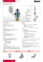
Press FLUSH valve push button to open flush valve - push button<br />
illuminates to indicate valve is open. Leave valve open for at least<br />
one minute or 200ml of fluid, to remove any entrapped air and<br />
fluid from the previous test ensuring no cross-contamination<br />
between samples.<br />
Press FLUSH valve push button to close flush valve - push button<br />
illumination is cancelled. Alternatively, proceed to step 10 - the<br />
action of pressing Start button automatically closes the flush<br />
valve before sampling commences.<br />
Press START button 1<br />
The Counter will now commence the sampling cycle<br />
The completion progress bar indicates the status of the sample.<br />
Results will be automatically displayed on the screen.<br />
Results will be automatically printed at the end of the sampling<br />
cycle, if the Auto Print mode has been turned ON<br />
If the Auto Print mode has been turned OFF, then Press Print key<br />
to obtain printed results<br />
Following the sampling results the Counter automatically<br />
discharges the sample fluid to waste.<br />
Test status is shown as Emptying.<br />
When the Sampling and Emptying cycle has been completed the<br />
test status is shown as Idle.<br />
Results are automatically stored to memory.<br />
To download results follow instructions on page 32.<br />
Laser Particle Counter OPERATION 11
<strong>LasPaC</strong> <strong>II</strong> – P User Guide<br />
Interpreting results<br />
Refer to pages 39 to 41 for hydraulic component manufacturers<br />
recommendations on standard cleanliness requirements for<br />
various applications.<br />
ONLINE - normal<br />
Particle count and ISO Code to 4406 standard<br />
(NAS Code 1638 displayed)<br />
ONLINE - dynamic<br />
ISO and NAS Code complete with average<br />
analysis<br />
ISO 4406 and NAS 1638 are not directly<br />
comparative. Please refer to page 41.<br />
right : ONLINE - normal<br />
Particle counts displayed -–<br />
NAS Code 1638 standard<br />
(ISO Code 4406 displayed)<br />
Laser Particle Counter OPERATION 12
<strong>LasPaC</strong> <strong>II</strong> – P User Guide<br />
Counter Upper Contamination Limit<br />
The Counter upper operating limit is set at 24/22/20.<br />
Tests that result in particle<br />
counts exceeding any scale<br />
number in the three part<br />
ISO upper limit has the<br />
scale number replaced by<br />
an asterisk. Also, the<br />
associated particle counts<br />
on the print-out are<br />
replaced by X’s. Refer to<br />
the example on the left.<br />
FURTHER TEST<br />
- same sampling point<br />
To repeat a test on the same sample point press START button, 1<br />
Note the test number will automatically increment.<br />
FURTHER TEST<br />
- different sampling point/same system<br />
To carry out this new test repeat steps 8 to 13 on page 12.<br />
To change test reference / test mode data, repeat steps 1 to 13 on<br />
page 9.<br />
FURTHER TEST<br />
- new system<br />
To carry out this test repeat steps 1 to 13 on page 9.<br />
Laser Particle Counter OPERATION 13
<strong>LasPaC</strong> <strong>II</strong> – P User Guide<br />
Shutting down<br />
1) Switch off Counter by pressing RED button<br />
2) Disconnect the FLUID SAMPLING HOSE from the<br />
system by means of the MINIMESS connector.<br />
This isolates the fluid supply.<br />
3) Remove the Fluid Sampling Hose from the<br />
Counter<br />
4) Remove Waste Fluid Hose from the Counter<br />
5) Replace hose end caps on sampling hose, wipe<br />
clean and store<br />
6) Connect Waste Fluid Hose quick coupling end<br />
fittings together, wipe clean and store.<br />
Laser Particle Counter OPERATION 14
<strong>LasPaC</strong> <strong>II</strong> – P User Guide<br />
CONTINUOUS SAMPLING<br />
The Counter can be selected for continuous testing at set time<br />
intervals.<br />
Once continuous sampling has started the Counter’s Flush valve<br />
automatically opens and closes before each test. This allows<br />
representative fluid to reach the sensing arrangement before the<br />
15ml sampling test commences.<br />
The Flush valve automatically opens at the end of the sampling<br />
cycle and remains open whilst the Counter is emptying to waste<br />
the sample fluid from the previous test. Additionally, depending<br />
on the time set for Minutes Between Tests, the Flush valve<br />
operates as follows:-<br />
Time set to 0:<br />
At the end of the Counter’s emptying cycle the Flush valve<br />
automatically closes and the next sampling test immediately<br />
starts.<br />
Time set to between 1 and 5:<br />
After the Counter’s emptying cycle has finished the Flush valve<br />
remains open for the time set, then automatically closes before<br />
the next sampling test.<br />
Time set to between 6 and 30000:<br />
Flush valve automatically closes after the emptying cycle has<br />
finished and remains closed until 5 minutes before the next<br />
sample test is programmed to start.<br />
Laser Particle Counter OPERATION 15
<strong>LasPaC</strong> <strong>II</strong> – P User Guide<br />
The Flush valve status is indicated by the push button<br />
illumination. Not illuminated means valve closed. Illuminated<br />
means valve open.<br />
The servo motor operating the Flush valve exhibits a slight<br />
‘ticking’ noise, both when it is open and closed. This is normal.<br />
Important! Do not connect Waste Fluid Hose to a pressurised<br />
system, as this will cause the Counter to malfunction and could<br />
cause internal leakage. The Waste Fluid Hose must be<br />
discharged into a tank/vessel vented to atmosphere.<br />
To conserve battery life, the Counter should be permanently<br />
connected to the power adaptor when it is operated in the<br />
continuous sampling mode.<br />
Continuous Sampling – BASIC OPERATION<br />
1<br />
Follow the section headed Operating The Counter, page 9,<br />
instructions 1 to 5 inclusive, to select the appropriate Counter<br />
settings.<br />
On the Operations Screen, press key 5 repeatedly until<br />
Continuous is selected.<br />
2<br />
Test Options – PRESS 6:<br />
Press relevant key to switch between option selections<br />
1) Minutes Between Tests – PRESS 1:<br />
Then input the time in minutes that is required<br />
between the end of a test and the beginning of a<br />
new test. Input a value between 1 and 30000.<br />
↵ RETURN<br />
2) PRESS 2 – Log Every Test: On, PRESS 2 –<br />
Selecting Log Every Test: Off will store none of the<br />
test results in the Counter’s memory.<br />
3) Clean Alarm Level (ISO) Level – PRESS 4:<br />
Then input 0 (zero)<br />
↵ RETURN<br />
Laser Particle Counter OPERATION 16
<strong>LasPaC</strong> <strong>II</strong> – P User Guide<br />
4) Clean Alarm Level (NAS1638/AS4059E-1) –<br />
PRESS 5:<br />
Then input 0 (zero)<br />
↵ RETURN<br />
5) Clean Alarm Level (AS4059E-2) -<br />
PRESS 6:<br />
Then input 0 (zero)<br />
↵ RETURN<br />
(The AS4059E-2 will now be displayed as<br />
*A/*B/*C/*D/*E/*F)<br />
3<br />
4<br />
5<br />
Press Flush valve push button to open Flush valve –<br />
push button illuminates to indicate valve is open. Leave valve<br />
open for at least 1 minute or 200ml of fluid, or more if the HP<br />
sampling hose is greater than 1.5m long.<br />
Press Flush valve push button to close Flush valve –<br />
push button illumination is cancelled. Alternatively, proceed to<br />
Step 5 below – the action of pressing Start button automatically<br />
closes the Flush valve before sampling commences.<br />
Press START button (key 1)<br />
The Counter will now commence the sampling procedure.<br />
Laser Particle Counter OPERATION 17
<strong>LasPaC</strong> <strong>II</strong> – P User Guide<br />
6<br />
7<br />
8<br />
The completion progress bar indicates the status of the test<br />
Results will be automatically displayed on the screen after each<br />
test.<br />
Results will be automatically printed at the end of the emptying<br />
cycle, if the Auto Print mode has been turned ON.<br />
The status is shown as Waiting between the ending of one test and<br />
the starting of the next test.<br />
Press Stop button (key 2) at any point in the cycle to end<br />
continuous sampling. The test status will show Idle.<br />
Continuous Sampling– with CLEAN ALARM<br />
LEVELS – ALARM MODE 1<br />
This operating mode is similar to the Basic Operation, but in this<br />
mode the Counter will stop testing when the specified clean alarm<br />
level is achieved.<br />
The status Completed is shown on the LCD when the specified<br />
clean alarm level is achieved.<br />
(For other Alarm Modes refer to page 26).<br />
9<br />
Follow the section headed Operating The Counter, instructions 1<br />
to 5 inclusive, to select the appropriate Counter settings<br />
On the Operations Screen, press key 5 repeatedly until<br />
Continuous is selected<br />
Laser Particle Counter OPERATION 18
<strong>LasPaC</strong> <strong>II</strong> – P User Guide<br />
10 Test Options – PRESS 6 :<br />
Press relevant key to switch between option selections<br />
1) Minutes Between Tests – PRESS 1:<br />
Then input the time in minutes that is required<br />
between the end of a test and the beginning of a<br />
new test. Input a value between 1 and 30000.<br />
↵ RETURN<br />
2) PRESS 2 – Log Every Test: On, PRESS 2 – Log Every Test:<br />
Off. Selecting Log Every Test: Off will only store the results<br />
of the test when the Clean alarm level is achieved – this saves<br />
on memory space.<br />
3) PRESS 3 – Confirm Cleanliness Level: On,<br />
PRESS 3 – Confirm Cleanliness Level: Off,<br />
Selecting Confirm Cleanliness Level: On instructs the Counter<br />
to repeat the sampling cycle until the Clean alarm level has<br />
been achieved in two consecutive samples, before the<br />
Completed status is displayed. Selecting Confirm Cleanliness<br />
Level: Off permits the Clean alarm level to be achieved only<br />
one time before the Completed status is displayed<br />
4) Clean Alarm Level (ISO) – PRESS 4:<br />
Then input desired Clean Alarm Level in the<br />
Code format Number/Number/Number – any code<br />
number combination can be input, from code 5 to<br />
code 24, example 10/9/5.<br />
↵ RETURN<br />
For continuous testing until the ISO Code is<br />
achieved, select ISO Format, as described under<br />
the previous section headed Operating The<br />
Counter, instruction 4, 1), page 9.<br />
Laser Particle Counter OPERATION 19
<strong>LasPaC</strong> <strong>II</strong> – P User Guide<br />
Testing will automatically continue until each of the<br />
three numbers in the Code have been achieved.<br />
5) Clean Alarm Level (NAS1638/AS4059E-1)<br />
– PRESS 5:<br />
Then input desired Clean Alarm Level, as a single<br />
Class number in the range 2 to 12 inclusive,<br />
example 6.<br />
↵ RETURN<br />
For continuous testing until the (NAS1638/ AS4059E-1) Class<br />
is achieved, select NAS Format or AS4059E Table 1, as<br />
described under the previous section headed ‘Operating The<br />
Counter’, Instruction 4, 1), page 9.<br />
Testing will automatically continue until the Class number has<br />
been achieved at each of the five micron size ranges covered<br />
by NAS 1638 & AS4049E Table 1.<br />
Note: AS4059E-1 denotes Table 1 of the AS4059E standard.<br />
6) Clean Alarm Level (AS4059E-2) – PRESS 6:<br />
Then input desired Clean Alarm Level in the format<br />
1A/2B/3C/4D/5E/6F in the following range:<br />
Size Code A: 000 to 12<br />
Size Code B: 00 to 12<br />
Size Code C: 00 to 12<br />
Size Code D: 2 to 12<br />
Size Code F: 4 to 12<br />
Size Code F: 7 to 12<br />
Example, 4A/4B/5C/6D/6E/7F<br />
For continuous testing until the AS4059E Table 2 Size codes<br />
are achieved, select AS4059E Table 2<br />
Laser Particle Counter OPERATION 20
<strong>LasPaC</strong> <strong>II</strong> – P User Guide<br />
11<br />
12<br />
Format, as described under the previous section headed<br />
Operating The Counter, instruction 4, 1), page 9. Testing will<br />
automatically continue until the Class number has been<br />
achieved at each of the six Size Codes.<br />
Also, the LASPAC <strong>II</strong> will handle deviations from the above<br />
format intelligently. The size code can be out of order:<br />
7F/4A/5C/4B/6E/6D<br />
If any of the sizes are missing, they will be assigned the “*”<br />
value. The effect of this is a “don't care“ value when used as<br />
the cleanliness target. For example, 6B/6C/7D is translated as<br />
*A/6B/6C/7D/*E/*F. In this case, testing will continue until<br />
the B, C and D Classes are less than or equal to 6, 6, 7<br />
respectively. The A, E and F Classes are effectively ignored<br />
since they cannot ever be “worse” than a “*” Class.<br />
Note: AS4059E-2 denotes Table 2 of the AS4059E standard.<br />
Press FLUSH valve push button to open flush valve - push button<br />
illuminates to indicate valve is open. Leave valve open for at least<br />
one minute or 200ml of fluid, to remove any entrapped air and<br />
fluid from the previous test ensuring no cross-contamination<br />
between samples.<br />
Press FLUSH valve push button to close flush valve - push button<br />
illumination is cancelled. Alternatively, proceed to step 13 - the<br />
action of pressing Start button automatically closes the Flush<br />
valve before sampling commences.<br />
Laser Particle Counter OPERATION 21
<strong>LasPaC</strong> <strong>II</strong> – P User Guide<br />
13<br />
14<br />
15<br />
16<br />
17<br />
Press START button (key 1)<br />
The Counter will now commence the sampling cycles<br />
The completion progress bar indicates the status of the test.<br />
Results will be automatically displayed on the screen after each<br />
test.<br />
• Results will be automatically printed at the end of the<br />
emptying cycle, if the Auto Print mode has been turned<br />
ON.<br />
The status is shown as Waiting between the ending of one test and<br />
the starting of the next test.<br />
Press Stop button (key 2) at any time in the cycle to end<br />
continuous sampling. The test status will show Idle.<br />
Laser Particle Counter OPERATION 22
<strong>LasPaC</strong> <strong>II</strong> – P User Guide<br />
MOISTURE SENSOR (optional)<br />
The LASPAC <strong>II</strong> version fitted with the optional moisture sensor<br />
module allows both measurement of % saturation of water in oil<br />
(Relative Humidity) and temperature. These are displayed as RH<br />
% and °C on the main/test progress screen and on the printed<br />
results.<br />
Temperature measurement provides a reference temperature for<br />
the RH reading.<br />
Due to the temperature gradient existing between the system<br />
tapping point and the RH/temperature module, the temperature<br />
reading can be 5°C to 10°C less than the actual system<br />
temperature, depending on operating conditions.<br />
The LASPAC <strong>II</strong> can be configured to do a test with or without the<br />
moisture sensor selected. If the moisture sensor has been selected,<br />
the flush valve will open automatically for a period of 3 minutes<br />
before the particle count test commences. This is to allow the<br />
moisture sensor to stabilize and give an accurate reading.<br />
To switch the moisture sensor ON or OFF, select the Test Option<br />
Screen, as described on page 11. The following will be<br />
displayed:-<br />
Test options screen<br />
1) Minutes Between Tests: 0<br />
2) Log Every Test: On<br />
3) Confirm Cleanliness Level: Off<br />
4) Clean Alarm Level (ISO): 0<br />
5) Clean Alarm Level (NAS1638/AS4059E-1): 0<br />
6) Clean Alarm Level (AS4059E-2):<br />
1A/2B/3C/4D/5E/6F<br />
7) RH Test: OFF<br />
Press a Key to Choose or 0 to Exit<br />
Press key 7 to change RH Test status to ON or OFF.<br />
Laser Particle Counter MOISTURE SENSOR 23
<strong>LasPaC</strong> <strong>II</strong> – P User Guide<br />
Laser Particle Counter MOISTURE SENSOR 24
<strong>LasPaC</strong> <strong>II</strong> – P User Guide<br />
ALARM OPTIONS<br />
Access the Operations screen as described on page 9 and<br />
PRESS 7 (Alarm Options). The following screen will be<br />
displayed:<br />
Alarm options screen<br />
1) Alarm Mode: 1<br />
2) Dirty Alarm Level (ISO): 0<br />
3) Dirty Alarm Level (NAS1638/AS4059E-1): 0<br />
4) Dirty Alarm Level (AS4059E-2):<br />
1A/2B/3C/4D/5E/6F<br />
Press a Key to Choose or 0 to Exit<br />
The LASPAC <strong>II</strong> includes two external circuit relays (solid state)<br />
that can be arranged to function as follows:<br />
Alam Mode: 0<br />
Selecting option 0 switches relays 1 and 2 always off.<br />
Alarm Mode: 1<br />
Selecting option 1 will configure relays 1 and 2 as described on<br />
page 28 - refer to the examples given on the simple wiring<br />
diagrams. Clean alarm levels are set in accordance with the<br />
instructions starting on page 19.<br />
Alarm mode 1 is used in conjunction with the Continuous<br />
Sampling test type, enabling the Counter to operate continuously<br />
until the specified clean alarm level is achieved.<br />
Alarm Mode: 2<br />
Selecting option 2 arranges the relays to operate when the Clean<br />
and Dirty alarm levels are reached/exceeded. Alarm mode 2 will<br />
normally be used in conjunction with the Continuous test type<br />
(refer to page 17), but can be used with all other test types as well.<br />
Set the Clean and Dirty alarm levels by inputting the desired<br />
levels into both the Test options screen (page 24) and the Alarm<br />
options screen, also setting the appropriate result format to ISO,<br />
NAS or AS4059, as described on page 9.<br />
Laser Particle Counter ALARM MODES 25
<strong>LasPaC</strong> <strong>II</strong> – P User Guide<br />
Both relays are initially off and remain off until an alarm level has<br />
been reached/exceeded.<br />
The following illustrates the switching logic of the Relays: -<br />
Relay 1 (Dirty)<br />
NAS/AS4059E-1 single number result > set limit On<br />
result corresponding set limit<br />
On<br />
all results
<strong>LasPaC</strong> <strong>II</strong> – P User Guide<br />
E<br />
EXTERNAL WIRING DETAILS<br />
For alarm / indication switching during Continuous Operation<br />
There are two external circuit relays (solid state). The function of<br />
these relays for Alarm Mode 1 is shown in the following simple<br />
wiring diagrams, using a battery and bulb circuit for illustrative<br />
purposes.<br />
Each relay is designed for a maximum current of 1 amp at 24 volt<br />
nominal AC or DC (absolute maximum 60 volt peak). Operation<br />
above these limits will cause irreparable damage to the relays.<br />
If the User requires to switch voltages/currents in excess of the<br />
above maximum limits, then separate higher rated interposing<br />
relays will need to be incorporated into the final electrical scheme<br />
designed by the User.<br />
Example 1: Bulb illuminates when Clean<br />
alarm level is achieved (completed status),<br />
and is off during sampling.<br />
Example 2: Bulb illuminates during sampling and<br />
extinguishes when Clean alarm level is achieved<br />
(completed status). [Relay 1 is also closed during<br />
Normal, Dynamic, Triple & Bottle and Short test<br />
types. Relay will open when stop button is pressed]<br />
BOTTLE SAMPLING – An alternative to operating on-line is to use STAUFF Bottle<br />
Sampling Unit to test oil contained in bottles. Refer to the separate User Guide for details.<br />
Laser Particle Counter WIRING – BOTTLE SAMPLING 27
<strong>LasPaC</strong> <strong>II</strong> – P User Guide<br />
MEMORY RECALL FACILITY<br />
Press Log button 6 to access results stored within the Counter’s<br />
memory, the Log Screen will be displayed.<br />
Log Screen<br />
1) Transfer Log<br />
2) Clear Log<br />
3) Clear Last<br />
4) Recall #0<br />
5) Print<br />
Press a Key to Choose or 0 to Exit<br />
To view the contents of the Counter’s memory progress through<br />
the following routine –<br />
Select Recall #0 - button 4 and enter the number of the test to be<br />
retrieved.<br />
If the test number is not known enter the last test number and<br />
scroll through the memory, using<br />
Next + or Previous - to select the required result.<br />
To print the result press Quit, button 0, and press button 5.<br />
A hard copy of the result will then be printed.<br />
Note: The result printed will be viewed in the results Presentation<br />
Options format from the Set function.<br />
Laser Particle Counter MEMORY RECALL 28
<strong>LasPaC</strong> <strong>II</strong> – P User Guide<br />
BATTERY CHARGING<br />
The Counter is equipped with an internal rechargeable battery<br />
capable of sustaining 8 hours continuous operation following a<br />
24-hour charging period (approximately 100 tests).<br />
To conserve battery power the LCD screen is illuminated at a<br />
reduced level when the Counter is operated without an external<br />
power supply connected.<br />
Low battery level INDICATOR<br />
When the indicator flashes the Counter requires recharging as<br />
soon as possible.<br />
BEFORE COMMENCING RECHARGING always press<br />
RED button to switch off the Counter.<br />
To recharge, connect lead from power adaptor to the DC power<br />
input socket on the Counter. Observe that battery charging<br />
indicator illuminates on the Counter.<br />
•<br />
•<br />
•<br />
Battery power may be conserved by:<br />
Operating Counter whilst connected to power adaptor<br />
Switching Counter OFF between samples<br />
Turning Auto Print Mode OFF<br />
Should the battery become completely discharged it is advisable<br />
to allow a minimum of 15 minutes charge time prior to<br />
commencing a test. The Counter must remain connected to the<br />
power adaptor during subsequent tests until the battery has had<br />
time to recharge.<br />
Laser Particle Counter BATTERY RECHARGING 29
<strong>LasPaC</strong> <strong>II</strong> – P User Guide<br />
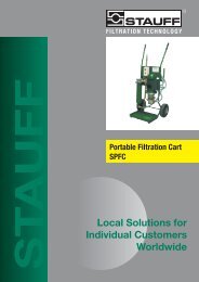
PRINTER PAPER<br />
To access the thermal printer, remove the four thumbscrews<br />
securing the cover and serrated paper cutter. Thermal printer paper<br />
is sensitized on one side only and must be fed into the printer<br />
mechanism as shown below.<br />
Using a finger, press down on the print head spring at position A<br />
and tilt the print head to the open position by pulling it back at<br />
point B<br />
Feed the paper under the roller and pull the paper end out of the<br />
mechanism. Return the print head back to its normal position by<br />
pressing on the green lever at point C. Ensure that the print head<br />
spring has returned to the position shown above.<br />
IMPORTANT: The thermal printer must not be operated without<br />
paper, as this will damage the printer. Therefore, replace the roll<br />
when the “end of the roll” indication appears on the paper.<br />
Laser Particle Counter PRINTER OPERATION 30
<strong>LasPaC</strong> <strong>II</strong> – P User Guide<br />
SOFTWARE INSTALLATION<br />
Install LASPAC <strong>II</strong> view software onto a suitable PC, this must be<br />
running Windows 95 ® / N.T.4.0 or better.<br />
Follow instructions as detailed in the LASPAC <strong>II</strong>-View User<br />
<strong>Manual</strong>.<br />
RESULTS DOWNLOAD<br />
1<br />
2<br />
3<br />
Connect RS232 cable to Counter and PC via an appropriate port.<br />
Switch ON the Counter.<br />
Switch ON the PC.<br />
Launch LASPAC <strong>II</strong> View software.<br />
From File select Upload.<br />
Data Transfer Screen will be displayed.<br />
Select appropriate COM Port.<br />
Select Transfer Data.<br />
The Counter will download all stored results from memory into<br />
the software package. Upon completion of download the Counter<br />
memory can be automatically deleted - if this option has been<br />
selected from the PC menu.<br />
4<br />
When the transfer is complete switch OFF the Counter.<br />
Laser Particle Counter SOFTWARE INSTALLATION 31
<strong>LasPaC</strong> <strong>II</strong> – P User Guide<br />
WARRANTY<br />
The <strong>LasPaC</strong> <strong>II</strong> is guaranteed for 12 months upon receipt of the<br />
Counter, subject to it being used for the purpose intended and<br />
operated in accordance with this User Guide.<br />
RECALIBRATION<br />
<strong>Stauff</strong> ® will only verify the accuracy of the <strong>LasPaC</strong> <strong>II</strong> if the unit<br />
is recalibrated every 12 months.<br />
Important! Please ensure that the test results in the Log are<br />
downloaded to <strong>LasPaC</strong> <strong>II</strong> View before the <strong>LasPaC</strong> <strong>II</strong> is<br />
despatched, in case action taken by <strong>Stauff</strong> ® during the service /<br />
recalibration causes the Log to be cleared.<br />
Ensure that the <strong>LasPaC</strong> <strong>II</strong> is packed appropriately for<br />
transportation.<br />
Laser Particle Counter WARRANTY 32
<strong>LasPaC</strong> <strong>II</strong> – P User Guide<br />
ISO 4406<br />
CLEANLINESS CODE SYSTEM*<br />
The International Standards<br />
Organisation standard<br />
ISO 4406 is the preferred method of<br />
quoting the number of solid<br />
contaminant particles in a sample.<br />
The code is constructed from the<br />
combination of three scale numbers<br />
selected from the following table.<br />
The first scale number represents the<br />
number of particles in a millilitre<br />
sample of the fluid that are larger<br />
than<br />
4 µm(c).<br />
The second number represents the<br />
number of particles larger than 6<br />
µm(c).<br />
The third number of particles that<br />
are larger than 14 µm(c).<br />
Table 5 - ISO 4406<br />
Allocation of Scale Numbers<br />
Number of Particles per ml Scale No.<br />
More<br />
than<br />
Up to and<br />
including<br />
2.5M - > 28<br />
1.3M 2.5M 28<br />
640k 1.3M 27<br />
320k 640k 26<br />
160k 320k 25<br />
80k 160k 24<br />
40k 80k 23<br />
20k 40k 22<br />
10k 20k 21<br />
5000 10k 20<br />
2500 5000 19<br />
1300 2500 18<br />
640 1300 17<br />
320 640 16<br />
160 320 15<br />
80 160 14<br />
40 80 13<br />
20 40 12<br />
10 20 11<br />
5 10 10<br />
2.5 5.0 9<br />
1.3 2.5 8<br />
0.64 1.3 7<br />
0.32 0.64 6<br />
0.16 0.32 5<br />
0.08 0.16 4<br />
0.04 0.08 3<br />
0.02 0.04 2<br />
0.01 0.02 1<br />
0.0 0.01 0<br />
Laser Particle Counter ISO 4406 33
Microscope counting examines the<br />
particles differently to APCs and the<br />
code is given with two scale<br />
numbers only. These are at 5 µm and<br />
15 µm equivalent to the 6 µm(c) and<br />
14 µm(c) of the APCs.<br />
ISO 4406<br />
Cleanliness Code Chart<br />
(with 100mL sample volume<br />
Laser Particle Counter ISO 4406 34
NAS 1638<br />
CLEANLINESS CODE SYSTEM*<br />
[NATIONAL AEROSPACE STANDARD]<br />
The NAS system was originally developed in 1964 to define contamination classes for the<br />
contamination contained within aircraft components. The application of this standard was<br />
extended to industrial hydraulic systems simply because nothing else existed at the time.<br />
The coding system defines the maximum numbers permitted of 100mL volume at various<br />
size intervals (differential counts) rather than using cumulative counts as in<br />
ISO 4406.<br />
Although there is no guidance given in the standard on how to quote the levels, most<br />
industrial users quote a single code which is the highest recorded in all sizes and this<br />
convention is used on the LASPAC <strong>II</strong>.<br />
CONTAMINATION LEVEL CLASSES according to NAS 1638 (January 1964)<br />
The contamination classes are defined by a number (from 00 to 12) which indicates the maximum<br />
number of particles per 100 ml, counted on a differential basis, in a given size bracket.<br />
MAXIMUM CONTAMINATION LIMITS (PER 100 mL)<br />
Size Range Classes (in microns)<br />
00 0 1 2 3 4 5 6 7 8 9 10 11 12<br />
5-15 125 250 500 1000 2000 4000 8000 16000 32000 64000 128000 256000 512000 1024000<br />
15-25 22 44 89 178 356 712 1425 2850 5700 11400 22800 45600 91200 182400<br />
25-50 4 8 16 32 63 126 253 506 1012 2025 4050 8100 16200 32400<br />
50-100 1 2 3 6 11 22 45 90 180 360 720 1440 2880 5760<br />
Over 100 0 0 1 1 2 4 8 16 32 64 128 256 512 1024<br />
Laser Particle Counter NAS 1638 35
SAE AS 4059 REV.E **<br />
CLEANLINESS CLASSIFICATION<br />
FOR HYDRAULIC FLUIDS<br />
[SAE AEROSPACE STANDARD]<br />
This SAE Aerospace Standard (AS) defines cleanliness levels for<br />
particulate contamination of hydraulic fluids and includes<br />
methods of reporting data relating to the contamination levels.<br />
Tables 1 and 2 below provide differential and cumulative particle<br />
counts respectively for counts obtained by an automatic particle<br />
counter, e.g. <strong>LasPaC</strong> <strong>II</strong>.<br />
TABLE 1 - Cleanliness Classes for Differential Particle Counts<br />
MAXIMUM CONTAMINATION LIMITS (PARTICLES<br />
/100mL)<br />
Size 6 to 14 14 to 21 21 tp 38 38 to 70 > 70<br />
µm (c) µm (c) µm (c) µm (c) µm (c)<br />
CLASSES<br />
00 125 22 4 1 0<br />
0 250 44 8 2 0<br />
1 500 89 16 3 1<br />
2 1,000 178 32 6 1<br />
3 2,000 356 63 11 2<br />
4 4,000 712 126 22 4<br />
5 8,000 1,425 253 45 8<br />
6 16,000 2,850 506 90 16<br />
7 32,000 5.700 1,012 180 32<br />
8 64,000 11,400 2,025 360 64<br />
9 128,000 22,800 4,050 720 128<br />
10 256,000 45,600 8,100 1,440 256<br />
11 512,000 91,200 16,200 2,880 512<br />
12 1,024,000 182,400 32,400 5,760 1,024<br />
Laser Particle Counter AS4059E 36
TABLE 2 - Cleanliness Classes for Cumulative Particle Counts<br />
MAXIMUM CONTAMINATION LIMITS (PARTICLES<br />
/100mL)<br />
Size >4 >6 >14 >21 >38 >70<br />
Size Code A B C D E F<br />
CLASSES<br />
000 195 76 14 3 1 0<br />
00 390 152 27 5 1 0<br />
0 780 304 54 10 2 0<br />
1 1,560 609 109 20 4 1<br />
2 3,120 1,217 217 39 7 1<br />
3 6,250 2,432 432 76 13 2<br />
4 12,500 4,864 864 152 26 4<br />
5 25,000 9,731 1,731 306 53 8<br />
6 50,000 19,462 3,462 612 106 16<br />
7 100,000 38,924 6,924 1,224 212 32<br />
8 200,000 77,849 13,849 2,449 424 64<br />
9 400,000 155,698 27,698 4,898 848 128<br />
10 800,000 311,396 55,396 9,796 1,696 256<br />
11 1,600,000 622,792 110,792 19,592 3,392 512<br />
12 3,200,000 1,245,584 221,584 39,184 6,784 1,024<br />
** The information reproduced on this and the previous page is a<br />
brief extract from SAE AS4059 Rev.E, revised in May 2005. For<br />
further details and explanations refer to the full Standard.<br />
Laser Particle Counter AS4059E 37
HYDRAULIC COMPONENT<br />
MANUFACTURER’S* RECOMMENDATIONS<br />
Most component manufacturers know the proportionate effect<br />
that increased dirt level has on the performance of their<br />
components and issue maximum permissible contamination<br />
levels. They state that operating components on fluids which are<br />
cleaner than those stated will increase life. However, the diversity<br />
of hydraulic systems in terms of pressure, duty cycles,<br />
environments, lubrication required, contaminant types, etc, makes<br />
it almost impossible to predict the components service life over<br />
and above that which can be reasonably expected. Furthermore,<br />
without the benefits of significant research material and the<br />
existence of standard contaminant sensitivity tests, manufacturers<br />
who publish recommendations that are cleaner than competitors<br />
may be viewed as having a more sensitive product.<br />
Hence there may be a possible source of conflicting information<br />
when comparing cleanliness levels recommended from different<br />
sources.<br />
The table below gives a selection of maximum contamination<br />
levels that are typically issued by component manufacturers.<br />
These relate to the use of the correct viscosity mineral fluid. An<br />
even cleaner level may be needed if the operation is severe, such<br />
as high frequency fluctuations in loading, high temperature or<br />
high failure risk.<br />
Laser Particle Counter RECOMMENDATIONS 38
Hydraulic<br />
Component<br />
Manufacturer’s<br />
Recommendations<br />
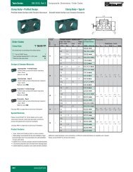
Unit Type ISO 4406 Code<br />
PUMP Piston (slow speed, in-line) 22/20/16<br />
Piston (high speed, variable) 17/15/13<br />
Gear 19/17/15<br />
Vane 18/16/14<br />
MOTOR Axial piston 18/16/13<br />
Radial piston 19/17/13<br />
Gear 20/18/15<br />
Vane 19/17/14<br />
VALVE Directional (solenoid) 20/18/15<br />
Pressure control (modulating) 19/17/14<br />
Flow control 19/17/14<br />
Check valve 20/18/15<br />
Cartridge valve 20/18/15<br />
Proportional 18/16/13<br />
Servovalve 16/14/11<br />
ACTUATOR 20/18/15<br />
Typical Manufacturer’s Recommendations for Component<br />
Cleanliness (ISO 4406)<br />
It should be noted that the recommendations made in this table<br />
should be viewed as starting levels and may have to be modified<br />
in light of operational experiences or user requirements.<br />
Laser Particle Counter RECOMMENDATIONS 39
HYDRAULIC SYSTEM TARGET CLEANLINESS LEVELS *<br />
Where a hydraulic system user has been able to check cleanliness<br />
levels over a considerable period, the acceptability, or otherwise,<br />
of those levels can be verified. Thus if no failures have occurred,<br />
the average level measured may well be one which could be made<br />
a bench mark. However, such a level may have to be modified if<br />
the conditions change, or if specific contaminant-sensitive<br />
components are added to the system. The demand for greater<br />
reliability may also necessitate an improved cleanliness level.<br />
The level of acceptability depends on three features<br />
• The contamination sensitivity of the components<br />
• The operational conditions of the system<br />
• The required reliability and life expectancy<br />
Contamination Correspondent Recommended Typical applications<br />
codes codes filtration<br />
ISO 4406 NAS 1638 degree<br />
4µm(c) 6µm(c) 14µm(c)<br />
B x ≥200<br />
14 12 9 3 3 High precision and<br />
laboratory servo-systems<br />
17 15 11 6 3-6 Robotic and servo-systems<br />
18 16 13 7 10-12 Very sensitive - high<br />
reliability systems<br />
20 18 14 9 12-15 Sensitive - reliable systems<br />
21 19 16 10 15-25 General equipment of<br />
limited reliability<br />
23 21 18 12 25-40 Low - pressure equipment<br />
not in continuous service<br />
Laser Particle Counter TARGETS 40
APPENDIX *<br />
New ISO Standard Test Dust and its effect on ISO Contamination<br />
Control Standards<br />
When General Motors gave advance warning to the International<br />
Standards Organisation (ISO) that it was intending to stop the<br />
production of AC Fine Test Dust (ACFTD), work commenced<br />
immediately on finding an improved replacement dust. ACFTD was<br />
used extensively within the fluid power and automotive industries for<br />
calibrating Automatic Particle Counters (APCs) and for the testing of<br />
components. APCs are used for testing oil filters, and also for<br />
contaminant sensitivity testing of hydraulic components.<br />
For 25 years, APCs have been the main stay in the measurement of<br />
solid particles in hydraulic fluids. The growth in demand for measuring<br />
fluid cleanliness in a variety of industrial processes, including fluid<br />
power, has resulted in APCs moving from the laboratory environment<br />
out into the factory. In fact, they are now a critical part of many<br />
production processes. It is therefore essential that the data they provide<br />
is both accurate and consistent.<br />
Calibration<br />
ACFTD has been used as an artificial contaminant since the 1960s and<br />
its original particles size distribution was determined using an optical<br />
microscope. This particle size distribution subsequently formed the<br />
basis of ISO 4402, the method for calibrating APCs. Due to the<br />
limitations of that method of measurement, the particle size distribution<br />
was questioned below about 5 microns. It was also not traceable to any<br />
national standard of measurement - a critical requirement for today’s<br />
quality management systems.<br />
There was also an absence of formal controls over the distribution of<br />
the test dust, and batch-to-batch variability was much greater than is<br />
acceptable nowadays.<br />
ISO therefore defined the requirements for the replacement for ACFTD<br />
and asked the National Institute of Standards and Technology (NIST) in<br />
the USA to produce a standard, traceable reference material. The new<br />
dust’s particle size distribution has been accurately determined with the<br />
aid of modern scanning electron microscope and image analysis<br />
techniques.<br />
New Test Dust Benefits<br />
The new ISO Medium Test Dust (ISOMTD) consists of similar<br />
materials to the old ACFTD, but to minimise particle counting errors, it<br />
is of a slightly coarser grade because ACFTD included too many<br />
particles smaller than 5 microns which gave problems during testing.<br />
Laser Particle Counter APPENDIX 41
ISOMTD is produced to a standard distribution and stringent quality<br />
control procedures, thereby ensuring excellent batch-to-batch<br />
repeatability. These procedures, combined with a revised ISO APC<br />
calibration method give:<br />
A traceable and controlled reference test dust with greatly reduced<br />
• variation in particle size distribution. This gives the traceability required<br />
by ISO 9000, QS9000 and similar quality management systems.<br />
•<br />
•<br />
•<br />
•<br />
•<br />
A procedure for determining the performance of APCs so that minimum<br />
acceptable levels can be set by the user.<br />
Improved calibration techniques and procedures.<br />
More accurate calibration.<br />
Improved levels of particle count reproducibility with different<br />
equipment.<br />
More accurate and consistent filter test results.<br />
Effect on Industry<br />
The introduction of ISOMTD has necessitated changes to certain ISO<br />
standards.<br />
The standards affected include:-<br />
ISO 4402<br />
ISO 4406<br />
ISO 4572<br />
: 1991 Hydraulic fluid power<br />
Calibration of liquid automatic particle counters.<br />
: 1987 Hydraulic fluid power<br />
Code for defining the level of contamination<br />
by solid particles.<br />
: 1981 Hydraulic fluid power Filters<br />
Multi-pass method for evaluating filtration performance of a filter<br />
element.<br />
In order that users are not confused by the changes to these standards,<br />
particularly by reference to them in technical literature, ISO is updating<br />
4402 to ISO 11171, and 4572 to ISO 16889.<br />
Two standards which concern our industry are the ISO 4406 coding<br />
system and the new ISO 16889 Multi-pass test. As APCs will<br />
henceforth count particles more accurately, there will now be a change<br />
in the way sizes are labelled.<br />
In the new ISO 4406, new calibration sizes are used to give the same<br />
cleanliness codes as the ‘old’ calibration sizes of 5 and 15 microns. In<br />
this way, there will be no necessity to change any system cleanliness<br />
specifications. It is proposed that the cleanliness codes (for APCs) will<br />
Laser Particle Counter APPENDIX 42
e formed from three* particle counts at 4, 6 and 14 microns, with 6<br />
and 14 microns corresponding very closely to the previous 5 and 15<br />
micron measurements. This will ensure consistency in data reporting.<br />
*The option of quoting just two counts of 6 microns and 14 microns for<br />
APCs remains.<br />
As the counts derived by microscope counting methods are not affected,<br />
the particle sizes used for microscopy will remain unchanged (i.e. at 5<br />
and 15 microns).<br />
To clarify matters still further, ISO standards written around the new<br />
test dust will utilise a new identifier, ‘(c)’. Hence micron sizes<br />
according to the new ISO 11171 will be expresses as ‘µm(c)’ and Beta<br />
ratios according to ISO 16889 will be expressed as ‘Bx(c)’, e.g. ‘B5(c)’.<br />
However, it must be stressed that the only real effect users will<br />
experience will be the improved accuracy in particle counts - there will<br />
be no change in the performance of filters, nor in the ISO cleanliness<br />
levels that they will achieve.<br />
The following charts shows the correlation between the old ACFTD and<br />
the new ISOMTD.<br />
The LASPAC <strong>II</strong> is calibrated with ISO Medium Test Dust (to ISO<br />
11171).<br />
The correlation between particle sizes and the ACFTD (old standard) to<br />
the ISOMTD (new standard) is as follows :<br />
ACFTD
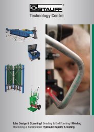
This table is only a<br />
guideline.<br />
The exact<br />
relationship<br />
between ACFTD<br />
sizes and the NIST<br />
sizes may vary from<br />
instrument to<br />
instrument<br />
depending<br />
on the<br />
characteristics of<br />
the particle counter<br />
and original<br />
ACFTD calibration<br />
Correlation between Particle Sizes Obtained using ACFTD<br />
(ISO 4402:1991) and NIST (ISO 11171) Calibration Methods<br />
Particle Size Obtained Using<br />
ACFTD SIZE (ISO 4402:1991) ISOMTD NIST (ISO 11171) size<br />
µm µm(c)<br />
1 4.2<br />
2 4.6<br />
3 5.1<br />
4 5.8<br />
5 6.4<br />
6 7.1<br />
7 7.7<br />
8 8.4<br />
9 9.1<br />
10 9.8<br />
11 10.6<br />
12 11.3<br />
13 12.1<br />
14 12.9<br />
15 13.6<br />
16 14.4<br />
17 15.2<br />
18 15.9<br />
19 16.7<br />
20 17.5<br />
21 18.2<br />
22 19.0<br />
23 19.7<br />
24 20.5<br />
25 21.2<br />
26 22.0<br />
27 22.7<br />
28 23.5<br />
29 24.2<br />
30 24.9<br />
31 25.7<br />
32 26.4<br />
33 27.1<br />
34 27.9<br />
35 28.5<br />
36 29.2<br />
37 29.9<br />
38 30.5<br />
39 31.1<br />
40 31.7<br />
Laser Particle Counter APPENDIX 44
Other standards<br />
Approximate<br />
Equivalents of<br />
Contamination<br />
Classes<br />
Although ISO 4406 standard is being used extensively within the<br />
hydraulics industry other standards are occasionally required and a<br />
comparison may be requested. The following table gives a very general<br />
comparison but often no direct comparison is possible due to the<br />
different classes and sizes involved.<br />
ISO 4406 DEF.STD 05/42 [7] NAS 1638[5] SAE 749[8]<br />
Table A Table B ISO 11218[6]<br />
13/11/08 - - 2 -<br />
14/12/09 - - 3 0<br />
15/13/10 - - 4 1<br />
16/14/09 - 400F - -<br />
16/14/11 - 5 2<br />
17/15/09 400 - - -<br />
17/15/10 - 800F - -<br />
17/15/12 - - 6 3<br />
18/16/10 800 - - -<br />
18/16/11 - 1,300F - -<br />
18/16/13 - - 7 4<br />
19/17/11 1,300 2,000F - -<br />
19/17/14 - - 8 5<br />
20/18/12 2,000 - - -<br />
20/18/13 - 4,400F - -<br />
20/18/15 - - 9 6<br />
21/19/13 4,400 6,300F - -<br />
21/19/16 - - 10 -<br />
22/20/13 6,300 - - -<br />
22/20/17 - - 11 -<br />
23/12/14 15,000 - - -<br />
23/21/18 - - 12 -<br />
24/22/15 21,000 - - -<br />
25/23/17 100,000 - - -<br />
* All section headings indicated with an asterix are reproduced by kind<br />
permission of British Fluid Power Association from BFPA/P5 1999 issue 3<br />
Laser Particle Counter APPENDIX 45
As a policy of<br />
continual<br />
improvement,<br />
<strong>Stauff</strong> ®<br />
reserve the<br />
right to alter<br />
the<br />
specification<br />
without prior<br />
notice<br />
Specification<br />
Technology<br />
Laser Package<br />
LCD display<br />
Sensitivity<br />
Accuracy / repeatability<br />
Calibration<br />
Automatic Optical Particle Counter<br />
Twin Laser and Twin Optical Diode Detectors<br />
(back lit)<br />
>4,6,14,21,25,38,50,70 µm(c), Micron range to<br />
revised ISO 4406 Standard<br />
Better than 3% typical<br />
Each unit is individually calibrated with ISO<br />
Medium Test Dust (MTD) based on ISO 11171:1999<br />
on equipment certified by I.F.T.S.<br />
Analysis Range ISO 8 to ISO 24 to ISO 4406<br />
NAS 1638: 2 to 12<br />
AS4059E Table 1: 2 to 12<br />
AS4059E Table 2: Size Codes A: 000 to 12, B: 00 to 12,<br />
C: 00 to 12, D: 2 to 12, E: 4 to 12, F: 7 to 12<br />
Report / Print Format<br />
Printer<br />
LASPAC <strong>II</strong> Sample volume<br />
Operation<br />
Viscosity range<br />
Operating temperature<br />
Fluid compatibility<br />
Typical test time<br />
Power<br />
Data storage<br />
Computer interface<br />
ISO, NAS and AS4059E codes/classes with Individual<br />
particle counts as a built-in option<br />
Fixed head thermal printer (384 dots per line)<br />
15 ml. (normal) 30 ml. (dynamic)<br />
24 ml. (bottle sampler) 15 ml. (continuous)<br />
8ml. (short)<br />
Max. system working pressure - 400 bar.<br />
Min. working pressure - 2 bar<br />
to 400 centistokes<br />
+5 to +80°C<br />
Mineral oil & petroleum based fluids<br />
(consult <strong>Stauff</strong> for other fluids)<br />
Result in
Spare product / part numbers<br />
Please contact <strong>Stauff</strong> for details<br />
Waste Hose 2m<br />
Pressure Hose 1.5m<br />
Product<br />
STAUFF – Ordering code<br />
<strong>LasPaC</strong> <strong>II</strong> - Waste hose 2m<br />
SMS-20-1500-A-C6F<br />
100ml certified clean bottle LasPac <strong>II</strong> - Bottle 110-C<br />
210ml certified clean bottle LasPac <strong>II</strong> - Bottle 250-C<br />
100ml glass sample bottle LasPac <strong>II</strong> - Bottle 110<br />
210ml glass sample bottle LasPac <strong>II</strong> - Bottle 250<br />
Printerpaper<br />
LasPac <strong>II</strong> - Printer Paper<br />
Battery Pack<br />
<strong>LasPaC</strong> <strong>II</strong> - M - Battery Pack<br />
Bottle-Sampler 110ml LasPac <strong>II</strong> - Bottle sampler 110<br />
Bottle-Sampler 250ml LasPac <strong>II</strong> - Bottle sampler 250<br />
Bottle-Sampler 250ml ( phosphate Ester ) LasPac <strong>II</strong> - Bottle sampler 250-E<br />
Screenfilter<br />
USB to serial port converter<br />
LasPac <strong>II</strong> - screen filter<br />
Adapter PPC-04/12-RS232-to-USB-CAB<br />
Laser Particle Counter PART NU<strong>MB</strong>ERS 47
Fault Finding<br />
FAULT<br />
1. LCD Screen remains<br />
blank after switching on<br />
CHECK<br />
• Check that Counter had been<br />
put on charge previously<br />
• Check that LED illuminates<br />
when power adaptor is<br />
connected to Counter DC<br />
Power Input Socket<br />
2. Unexpected results obtained<br />
from sample<br />
• Check that the fluid sampling<br />
hose has been fully connected<br />
at both the system and<br />
Counter ends<br />
• Confirm that there is a free<br />
flow of fluid to the Counter,<br />
by depressing the Flush Valve<br />
and observing fluid passing<br />
into the waste disposal bottle<br />
• High water/aeration levels.<br />
(If suspected contact <strong>Stauff</strong><br />
for further advice)<br />
If excessive system contamination is suspected, flush out the Counter using<br />
a Bottle Sampling Unit in conjunction with a suitable solvent.<br />
The standard LASPAC <strong>II</strong> and the standard Bottle Sampling units are both<br />
fitted with Nitrile seals, so Petroleum Ether may be used for this purpose.<br />
Petroleum Ether is not compatible with seals manufactured from EPDM,<br />
which are used in the Skydrol ® version of the 250 Bottle Sampling unit.<br />
DO NOT USE ACETONE<br />
Laser Particle Counter FAULT FINDING 48
<strong>LasPaC</strong> <strong>II</strong> - Registration<br />
To get further information on your <strong>LasPaC</strong> <strong>II</strong> please register at<br />
www.stauff.com/register.<br />
A registration provides the following advantages:<br />
- Download of the newest <strong>LasPaC</strong> <strong>II</strong> - View Software<br />
- Information about possible Firmware updates<br />
- Downloadable manuals<br />
- Information to the next calibration date<br />
- and much more...<br />
Laser Particle Counter REGISTRATION 49
<strong>Stauff</strong> ® locations, worldwide<br />
AUSTRALIA<br />
STAUFF Corporation Pty.<br />
Ltd.<br />
P.O. Box 227<br />
Wollongong, NSW, 2526<br />
24-26 Doyle Avenue<br />
Unanderra , Wollongong,<br />
NSW, 2526<br />
Tel.: +61 2 4271 18 77<br />
Fax: +61 2 4271 84 32<br />
sales@stauff.com.au<br />
BRAZIL<br />
STAUFF Brasil Ltda.<br />
Avenida Gupê 10767<br />
Galpão 2 – Bloco A<br />
Barueri – Sãu Paulo<br />
CEP 06422-120<br />
Tel.: +55 11 47 72 72 00<br />
Fax: +55 11 47 72 72 10<br />
stauff@stauffbrasil.com<br />
CANADA<br />
STAUFF Canada Ltd.<br />
866 Milner Avenue<br />
Scarborough<br />
Ontario M1B 5N7<br />
Tel.: +1 416 282 46 08<br />
Fax: +1 416 282 30 39<br />
sales@stauffcanada.co<br />
m<br />
CHINA<br />
STAUFF International<br />
Trading<br />
(Shanghai) Co., Ltd.<br />
No. 41 –42, Lane 369,<br />
Chuang Ye Road<br />
Jushuo Industrial Zone, Kang<br />
Qiao<br />
201319 Shanghai<br />
Tel.: +86 21 68 18 70 00<br />
Fax: +86 21 68 18 71 36<br />
info@stauff.com.cn<br />
FRANCE<br />
230, Avenue du Grain d’Or<br />
Z.I. Vineuil – Blois Sud<br />
41354 Vineuil – cedex<br />
Tel.: +33 2 54 50 55 50<br />
Fax: +33 2 54 42 29 19<br />
Tel.: +82 51 266 6666<br />
direction@stauffsa.comFax: +82 51 266 8866<br />
info@stauff.co.kr<br />
GERMANY<br />
Walter <strong>Stauff</strong>enberg GmbH & NEW ZEALAND<br />
Co. KG<br />
STAUFF Corporation<br />
P.O. Box 1745<br />
P.O. Box 58517<br />
5877 Werdohl<br />
Greenmount, Auckland<br />
Im Ehrenfeld 4<br />
Unit D, 103 Harris Road<br />
58791 Werdohl<br />
East Tamaki, Auckland<br />
Tel.: +49 2392 916-0 Tel.: +64 9 271 48 12<br />
Fax: +49 2392 2505 Fax.: +64 9 271 48 32<br />
sales@stauff.com info@stauff.co.nz<br />
INDIA<br />
POLAND<br />
STAUFF India Pvt. Ltd. STAUFF Polska Sp. z o.o.<br />
Gat. No. 2340<br />
Miszewko 43 A<br />
Pune Nagar Road, Wagholi 80-297 Banino<br />
Pune, 412207<br />
Tel.: +48 58 660 11 60<br />
Tel.: +91 20 6620 2473 Fax: +48 58 629 79 52<br />
Fax: +91 20 2705 1567 sales@stauff.pl<br />
sales@stauffindia.com<br />
ITALY<br />
STAUFF Italia s.r.l.<br />
Viale Nuova Valassina 78<br />
Angolo Via Baragiola sn<br />
20033 Desio (MI)<br />
Tel.: +39 0362 63 80 70<br />
Fax: +39 0362 63 80 69<br />
sales@stauff.it<br />
IRELAND<br />
STAUFF Ireland Ltd.<br />
Unit B3<br />
Weatherwell Buisness Park<br />
Clondalkin<br />
Dublin 22<br />
Tel.: +353 1457 4936<br />
Fax: +353 1467 0687<br />
sales@stauff.ie<br />
KOREA<br />
STAUFF Korea Ltd.<br />
1500-12, Dadae-Dong<br />
Saha-Ku<br />
Pusan, 604-826<br />
RUSSIAN FEDERATION<br />
STAUFF LLC<br />
Office 205, Building 7<br />
Scharikopodschipnikovskaya 11<br />
Moscow, 115088<br />
Tel.: +7 495 987 36 29<br />
Fax: +7 495 679 90 48<br />
sales@stauff.ru<br />
UNITED KINGDOM<br />
STAUFF UK<br />
500, Carlisle Street East<br />
Off Downgate Drive<br />
Sheffield, S4 8BS<br />
Tel.: +44 114 251 85 18<br />
Fax : +44 114 251 85 19<br />
sales@stauff.co.uk<br />
UNITED STATES<br />
STAUFF Corporation<br />
7 Wm. Demarest Place<br />
Waldwick, 07463-1542<br />
New Jersey<br />
Tel.: +1 201 444 78 00<br />
Fax : +1 201 444 78 52<br />
Sales@stauffusa.com<br />
Globally available through<br />
wholly-owned braches and<br />
distributors in all industrial<br />
countries.<br />
Laser Particle Counter<br />
STAUFF ® locations, worldwide