Lab 8-1 Securing the Layer 2 Switching Devices
Lab 8-1 Securing the Layer 2 Switching Devices
Lab 8-1 Securing the Layer 2 Switching Devices
You also want an ePaper? Increase the reach of your titles
YUMPU automatically turns print PDFs into web optimized ePapers that Google loves.
Step 1<br />
Step 2<br />
When you get back to <strong>the</strong> office, you meet with your boss to discuss your<br />
concerns. After reviewing <strong>the</strong> company’s security policies, you begin to work on<br />
a <strong>Layer</strong> 2 security policy.<br />
First, you establish which network threats you are concerned about and <strong>the</strong>n<br />
put toge<strong>the</strong>r an action plan to mitigate <strong>the</strong>se threats. While researching <strong>the</strong>se<br />
threats, you learn about o<strong>the</strong>r potential threats to <strong>Layer</strong> 2 switches that might<br />
not be malicious but could greatly threaten network stability. You decide to<br />
include <strong>the</strong>se threats in <strong>the</strong> policies as well.<br />
O<strong>the</strong>r security measures need to be put in place to fur<strong>the</strong>r secure <strong>the</strong> network,<br />
but you begin with configuring <strong>the</strong> switches against a few specific types of<br />
attacks, including MAC flood attacks, DHCP spoofing attacks, and unauthorized<br />
access to <strong>the</strong> local network. You plan to test <strong>the</strong> configurations in a lab<br />
environment before placing <strong>the</strong>m into production.<br />
Power up <strong>the</strong> switches and use <strong>the</strong> standard process for establishing a<br />
HyperTerminal console connection from a workstation to each switch in your<br />
pod.<br />
Remove all VLAN information and configurations that were previously entered<br />
into your switches. (Refer to <strong>Lab</strong> 2.0a or 2.0b if needed.)<br />
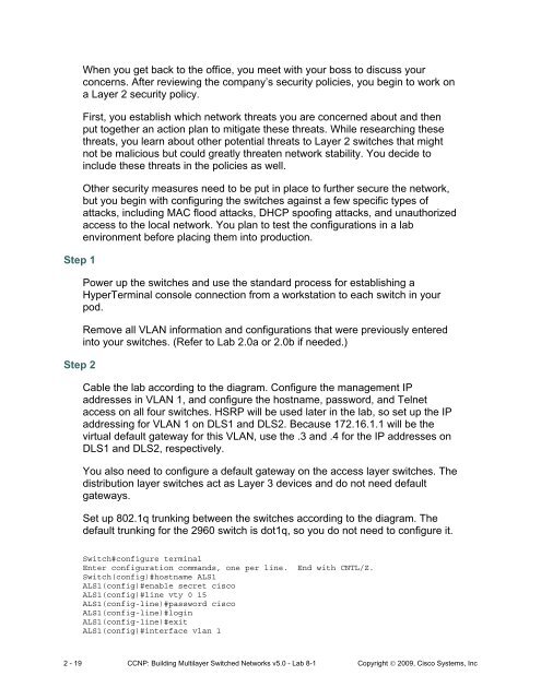
Cable <strong>the</strong> lab according to <strong>the</strong> diagram. Configure <strong>the</strong> management IP<br />
addresses in VLAN 1, and configure <strong>the</strong> hostname, password, and Telnet<br />
access on all four switches. HSRP will be used later in <strong>the</strong> lab, so set up <strong>the</strong> IP<br />
addressing for VLAN 1 on DLS1 and DLS2. Because 172.16.1.1 will be <strong>the</strong><br />
virtual default gateway for this VLAN, use <strong>the</strong> .3 and .4 for <strong>the</strong> IP addresses on<br />
DLS1 and DLS2, respectively.<br />
You also need to configure a default gateway on <strong>the</strong> access layer switches. The<br />
distribution layer switches act as <strong>Layer</strong> 3 devices and do not need default<br />
gateways.<br />
Set up 802.1q trunking between <strong>the</strong> switches according to <strong>the</strong> diagram. The<br />
default trunking for <strong>the</strong> 2960 switch is dot1q, so you do not need to configure it.<br />
Switch#configure terminal<br />
Enter configuration commands, one per line. End with CNTL/Z.<br />
Switch(config)#hostname ALS1<br />
ALS1(config)#enable secret cisco<br />
ALS1(config)#line vty 0 15<br />
ALS1(config-line)#password cisco<br />
ALS1(config-line)#login<br />
ALS1(config-line)#exit<br />
ALS1(config)#interface vlan 1<br />
2 - 19 CCNP: Building Multilayer Switched Networks v5.0 - <strong>Lab</strong> 8-1 Copyright © 2009, Cisco Systems, Inc


