SIGNEX PST96 Isopatch series user manual - Canford Audio
SIGNEX PST96 Isopatch series user manual - Canford Audio
SIGNEX PST96 Isopatch series user manual - Canford Audio

You also want an ePaper? Increase the reach of your titles
YUMPU automatically turns print PDFs into web optimized ePapers that Google loves.
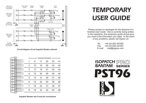
See Fig. #<br />
for D-sub pin<br />
connections<br />
Rear D-sub<br />
connector<br />
(part)<br />
Chassis<br />
ground point<br />
(Ch. 48 only)<br />
G<br />
Rear solder<br />
points<br />
T<br />
R<br />
S<br />
Parallel<br />
points<br />
T<br />
R<br />
S<br />
Jumper<br />
cable<br />
Program<br />
pads<br />
T2<br />
T1<br />
R2<br />
R1<br />
S<br />
Top PCB<br />
Front<br />
Jacks<br />
Front<br />
panel<br />
TEMPORARY<br />
USER GUIDE<br />
Rear D-sub<br />
connector<br />
(part)<br />
T<br />
R<br />
S<br />
T<br />
R<br />
S<br />
Bottom PCB<br />
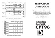
Please accept our apologies for the absence of a<br />
finished User Guide - this is currently being written.<br />
In the meantime, this temporary guide should give<br />
you most of the information you need. In the event<br />
of any problems, please call Signex on:<br />
Chassis<br />
ground point<br />
(Ch. 48 only)<br />
G<br />
Circuit diagram of one <strong>Isopatch</strong> Bantam channel<br />
Tel: +44 (0)1202 247000<br />
Fax: +44 (0)1202 247001<br />
E-mail: mail@signex.com<br />
25<br />
24<br />
23<br />
22<br />
21<br />
20<br />
19<br />
18<br />
17<br />
16<br />
15<br />
14<br />
13<br />
12<br />
11<br />
10<br />
9<br />
8<br />
7<br />
6<br />
5<br />
4<br />
3<br />
2<br />
1<br />
S<br />
R<br />
T<br />
S<br />
R<br />
T<br />
S<br />
R<br />
T<br />
S<br />
R<br />
T<br />
S<br />
R<br />
T<br />
S<br />
R<br />
T<br />
S<br />
R<br />
T<br />
S<br />
R<br />
T<br />
1<br />
2<br />
3<br />
4<br />
5<br />
6<br />
7<br />
8<br />
9<br />
10<br />
11<br />
12<br />
13<br />
14<br />
15<br />
16<br />
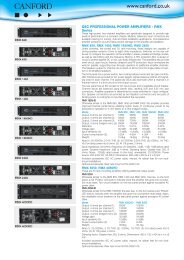
Channel Number<br />
17 25<br />
18 26<br />
19 27<br />
20 28<br />
21 29<br />
22 30<br />
23 31<br />
24 32<br />
33<br />
34<br />
35<br />
36<br />
37<br />
38<br />
39<br />
40<br />
41<br />
42<br />
43<br />
44<br />
45<br />
46<br />
47<br />
48<br />
ISOPATCH PRO<br />
BANTAM SERIES<br />
<strong>PST96</strong><br />
<strong>Isopatch</strong> Bantam rear D-sub pin connections<br />
PRO AUDIO PRODUCTS
Half or full normalising<br />
The <strong>Isopatch</strong> Bantam offers a choice of half or full normalising on every channel. When half<br />
normalised (sometimes called Sniff and Break), the link between the sockets is broken only when a<br />
plug is inserted into the bottom socket (half of the pair of sockets). The top socket can be plugged into<br />
without breaking the link to the socket below, allowing the signal to be <strong>manual</strong>ly patched into another<br />
input whilst still connected to its ‘normal’ destination. This configuration is particularly useful because it<br />
allows an output to be split and sent to two inputs simultaneously. In this situation, the ‘normal’ link can<br />
still be broken by simply inserting an unconnected jack plug or patch cord into the bottom socket.<br />
When a pair is fully normalised, the link between the sockets is broken when a plug is inserted into<br />
either the top or bottom socket. This option should be used when an output must not be routed to more<br />
than one input at a time.<br />
Half normal<br />
Full normal<br />
R1<br />
T1<br />
S<br />
Half normal<br />
R1<br />
T1<br />
S<br />
Full normal<br />
T2, R2 & S<br />
T1, R1 & S<br />
T2<br />
T2<br />
R2<br />
R2<br />
Normalising a channel on the <strong>Isopatch</strong> Bantam<br />
Signal Type<br />
Tip<br />
Ring<br />
Sleeve<br />
Mono (Unbalanced)<br />
Signal<br />
Ground<br />
Programming normalising<br />
The <strong>Isopatch</strong> Bantam is supplied with all sockets isolated<br />
(not normalised) but any channel may be easily normalised<br />
by soldering across special ‘program pads’ on the top printed circuit board (PCB). There are five<br />
program pads on each channel and they act like switches - soldering across a program pad is like<br />
closing a switch. When soldering a program pad, more solder is needed than for a normal joint<br />
because the solder has to 'bridge' the gap in the pad. When bridged, the joint on the program pad will<br />
look like a bead of solder. Take care not to get solder anywhere else on the PCB as this could cause a<br />
short circuit and possibly damage the equipment connected to the <strong>Isopatch</strong> Bantam. If you have no<br />
experience soldering, then ask your dealer to do this for you. To program normalising on any channel,<br />
Mono (Balanced)<br />
Stereo (Unbalanced) *<br />
Digital (SPDIF)<br />
Digital (AES/EBU)<br />
+ (Hot)<br />
Right<br />
Signal<br />
+ (Hot)<br />
- (Cold)<br />
Left<br />
- (Cold)<br />
Ground<br />
Ground<br />
Ground<br />
Ground<br />
Bantam<br />
Jack<br />
* Left and right channels may be<br />
reversed.<br />
Note: Screen is always ground<br />
Wiring of different signal types to a Bantam Jack