Model 2500 DIN Rail Controller DECLARATION OF ... - d a n m a r k
Model 2500 DIN Rail Controller DECLARATION OF ... - d a n m a r k
Model 2500 DIN Rail Controller DECLARATION OF ... - d a n m a r k

Create successful ePaper yourself
Turn your PDF publications into a flip-book with our unique Google optimized e-Paper software.
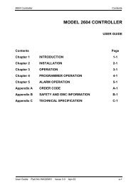
I1 D1 I2 D2<br />
AO2 - Analogue Output Module<br />
Milli-amps (mA)<br />
Shunt Option<br />
Voltage, mA<br />
AI2<br />
H1 B1 H2 B2<br />
I1 D1 I2 D2<br />
A1 C1 A2<br />
mA<br />
-C1<br />
C2<br />
AO2<br />
1+ 1- 2+ 2-<br />
1+ 1- 2+ 2-<br />
1+ 1- 2+ 2-<br />
Note Voltage Mode. Input impedance ‘Rv’ of the device connected<br />
to this output module must be > 550Ω for 0Vdc to 10Vdc<br />
range and > 1500Ω for the -0.1Vdc to +10.1Vdc range.<br />
Current Mode. Input impedance (or loop impedance) ‘Ri’ of<br />
the device connected to this output module must be < 550Ω.<br />
RLY4 - Relay Module DI8 - Digital Input Module<br />
Relay Output<br />
RLY<br />
Voltage Source<br />
Inputs<br />
DI8<br />
Contact Inputs<br />
DI8<br />
+A2 -C2<br />
mA<br />
mA<br />
mA<br />
Fuse<br />
Carrier<br />
1 3 5 7<br />
1 3 5<br />
B1 B2<br />
B3 B4<br />
1C2 3C4 5C6 7C8<br />
1C2 3C4 5C6 7C8<br />
DO4 - Digital Output Module<br />
A1<br />
A2 A3 A4<br />
2 4 6<br />
8<br />
2 4 6<br />
8<br />
AI3 - Analogue Input Module<br />
Logic Outputs<br />
C4<br />
1 1C2 2<br />
1 1C2 2<br />
4 - 20mA module<br />
powered inputs<br />
4 - 20mA self<br />
powered inputs<br />
D4<br />
A1 B1 A2 B2 A3 B3 B4 A4 C4<br />
+ +<br />
3 3C4 4<br />
Basic 50V<br />
Isolation<br />
3 3C4 4<br />
AI3<br />
P1 P2 P3<br />
C1 C2 C3<br />
I1 I2 I3<br />
AI3<br />
P1 P2 P3<br />
C1 C2 C3<br />
I1 I2 I3<br />
+<br />
-<br />
1 2 3 4<br />
C C C C<br />
+V +V C<br />
* Voltage<br />
Supply<br />
C<br />
Logic Outputs<br />
To<br />
Additional<br />
Modules<br />
Notes.<br />
1 Relays above shown in power off<br />
state<br />
2 Fuses supplied for the Relay units<br />
are 3.15A (T type), 20mm to<br />
EN60127.<br />
3 Fitted labels show manufacturing<br />
data including space to record<br />
which snubbers have been<br />
removed.<br />
+<br />
5 5C6 6<br />
+<br />
+<br />
+<br />
7 7C8 8<br />
+ +<br />
Basic 50V<br />
Isolation<br />
Basic 50V<br />
Isolation<br />
5 5C6 6<br />
7 7C8 8<br />
mA<br />
P1<br />
C1<br />
mA<br />
P2<br />
C2<br />
mA<br />
P3<br />
C3<br />
I1 I2<br />
mA mA mA<br />
C1 C2<br />
Note C1 to C3 is +ve.<br />
P3<br />
C3<br />
C<br />
1<br />
1<br />
C<br />
2<br />
2<br />
C<br />
3<br />
3<br />
C<br />
4<br />
4<br />
Logic Inputs<br />
Contact Inputs<br />
Note Functional Insulation. This is defined as: Insulation between conductive<br />
parts that is necessary only for the proper functioning of the equipment. This<br />
does not necessarily provide protection against electric shock.<br />
Reinforced Insulation. This is defined as: Insulation between conductive<br />
parts, which provides protection against electric shock.<br />
SHUNT<br />
AI2 - Analogue Input Module<br />
2-, 3-, 4-wire<br />
Platinum Resistance<br />
Thermocouple Thermometer<br />
(T/C)<br />
(PRT)<br />
AI2<br />
AI2<br />
H1 B1 H2 B2<br />
Potentiometer<br />
Input<br />
AI2<br />
H1 B1 H2 B2<br />
High Impedance<br />
Input<br />
(Zirconia Probe)<br />
AI2<br />
AI4 - Analogue Input Module<br />
Thermocouple<br />
(TC)<br />
AI-TC<br />
2+ 2- 4+ 4-<br />
Milli-volts<br />
(mV)<br />
AI-TC<br />
2+ 2- 4+ 4-<br />
Dual milli-amps<br />
(mA) Shunt Option<br />
AI-mA<br />
A2 C2 A4 C4<br />
Note The Shunt option has 5Ω<br />
resistors mounted on the<br />
PCB. The mV option may<br />
also be used for mA inputs if<br />
fitted with a suitable external<br />
5W burden resistor. This<br />
permits a 0 - 20mA input to<br />
provide a full-scale range of<br />
0 - 100mV.<br />
DI4 - Digital Input Module<br />
Voltage Source<br />
Inputs<br />
DI4<br />
1 2 3 4<br />
C C C C<br />
Contacts Input<br />
Externally Powered<br />
DI4<br />
1 2 3 4<br />
C C C C<br />
DI6 - Digital Input Module<br />
115 and 230 V<br />
ac Inputs<br />
DI6<br />
L5 N5 L6 N6<br />
L3 N3 L4 N4<br />
I1 D1 I2 D2<br />
1+ 1- 3+ 3-<br />
1+<br />
1- 3+<br />
3-<br />
A1 C1 A3<br />
C3<br />
+V +V C<br />
C<br />
+V +V C<br />
C<br />
L1 N1 L2<br />
N2<br />
+ +<br />
2+ 2- 4+ 4-<br />
A2 C2<br />
A4 C4<br />
See Note 2 +V +V C C<br />
L5<br />
N5 L6 N6<br />
1+ 1- 2+<br />
+ +<br />
2-<br />
A1 C1 A2<br />
See Note 1<br />
I1 A1 C1<br />
PRT<br />
or<br />
C2<br />
I1 B1<br />
PRT<br />
A1 C1<br />
+I1<br />
A1 C1 A2<br />
A1<br />
-C1<br />
C2<br />
1+ 1- 2+<br />
2-<br />
+ +<br />
mV<br />
mV<br />
mV<br />
1+ 1- 3+ 3-<br />
mV<br />
mV<br />
1+ 1-<br />
mV<br />
mV<br />
A3 C3<br />
mV<br />
1 C+V C 2 C<br />
+ +<br />
+<br />
-<br />
Voltage<br />
Supply<br />
1 C 2 C<br />
To<br />
Additional<br />
Modules<br />
L3 N3 L4 N4<br />
I2 A2 C2<br />
PRT<br />
or<br />
I2 B2<br />
PRT<br />
A2 C2<br />
+I2<br />
A2<br />
-C2<br />
2+ 2-<br />
Zr<br />
3 C 4 C<br />
+ +<br />
3 C 4 C<br />
L1 N1 L2 N2<br />
Volts (V) or milli-Volt<br />
(mV)<br />
Logic Inputs<br />
Contact Inputs<br />
See Notes 3<br />
+H1 -C1<br />
V<br />
AI2<br />
H1 B1 H2 B2<br />
I1 D1 I2 D2<br />
A1 C1 A2<br />
or<br />
C2<br />
+A1 -C1<br />
mV<br />
See Note 2<br />
+A1<br />
Notes<br />
1 Channel 1 - PRT 2-wire connection uses<br />
I1 and C1 only.<br />
Channel 2 - PRT 2-wire connection uses<br />
I2 and C2 only.<br />
2 The Shunt option has 5Ω resistors<br />
mounted on the PCB.<br />
3 The Table below shows the Dual Volts (V)<br />
or milli-Volts (mV) Channel wiring.<br />
HR_in to LR_in Terminal<br />
Channel Limits Connections<br />
CH1 -150mV to +150mV A1 and C1<br />
-10Vdc to +10Vdc C1 and H1<br />
Rv<br />
Ri<br />
Rv<br />
Ri<br />
Notes<br />
1 Negative logic inputs can be connected if<br />
required. Reverse the polarity of the input<br />
connections.<br />
2 A link (+V to C) MUST be fitted in place of<br />
external supply.<br />
+H2 -C2<br />
V<br />
or<br />
+A2 -C2<br />
V<br />
CH2 150mV to +150mV C2 and A2<br />
0 to 1.8Vdc C2 and A2<br />
-10Vdc to +10Vdc C2 and H2<br />
7<br />
+A2 -C2<br />
mV<br />
Note *External power supply to power plant devices.<br />
SHUNT<br />
Installation Safety Requirements<br />
Various symbols used on the instrument are described below:<br />
!<br />
Caution (refer to the<br />
accompanying documents)<br />
Functional<br />
(ground) earth<br />
Protective earth<br />
terminal<br />
INSTALLATION CATEGORY AND POLLUTION DEGREE<br />
This product has been designed to conform to BS EN61010 installation category II<br />
and pollution degree 2. These are defined as follows:<br />
• Installation category II. The rated impulse voltage for equipment on nominal<br />
230V ac mains is <strong>2500</strong>V.<br />
• Pollution degree 2. Normally, only non-conductive pollution occurs. However,<br />
occasionally a temporary conductivity caused by condensation can be expected.<br />
Personnel<br />
Installation must only be carried out by qualified personnel.<br />
Enclosure of live parts<br />
To prevent hands or metal tools touching parts that may be electrically live, the unit<br />
must be installed in an enclosure.<br />
Blank Terminal Unit<br />
Base Units are supplied to hold 16 modules. In the event that a Base Unit is not fully<br />
populated a blank terminal unit, Part no. 026373, will be supplied with the unit. It is<br />
important to fit this immediately to the right of the last module in order to maintain<br />
IP20 rating.<br />
Caution: Live sensors<br />
The unit is designed to operate with the temperature sensor connected directly to an electrical<br />
heating element. However you must ensure that service personnel do not touch connections to<br />
these inputs while they are live. With a live sensor, all cables, connectors and switches for<br />
connecting the sensor must be mains rated.<br />
Wiring<br />
It is important to connect the unit in accordance with the wiring data given in this<br />
instruction sheet. Take particular care not to connect AC supplies to the low voltage<br />
sensor input or other low level inputs and outputs. Only use copper conductors for<br />
connections (except thermocouple inputs) and the wiring of installations comply<br />
with all local wiring regulations. For example in the UK use the latest version of the<br />
IEE wiring regulations (BS7671). In the USA use NEC Class 1 wiring methods.<br />
Power Isolation<br />
The installation must include a power isolating switch or circuit breaker. This device<br />
should be in close proximity (1 meter) to the unit, within easy reach of the operator<br />
and marked as the disconnecting device for the instrument.<br />
Earth Leakage Current<br />
Due to RFI Filtering there may be an earth leakage current of up to 3.5mA. This may<br />
affect the design of an installation of multiple units protected by Residual Current<br />
Device (RCD) or Ground Fault Detector, (GFD) type circuit breakers.<br />
Overcurrent Protection<br />
It is recommended that the DC power supply to the system is fused appropriately to<br />
protect the cabling to the unit. The unit provides a fuse on the <strong>2500</strong> module to protect<br />
the supply from a fault within the unit.<br />
Voltage Rating<br />
The maximum continuous voltage applied between any of the following terminals<br />
must not exceed 264Vac:<br />
• DI6 input or RLY4 relay output to logic, dc or sensor connections;<br />
• any connection to ground<br />
The unit must not be wired to a three-phase supply with an unearthed<br />
star connection. Under fault conditions such a supply could rise above 264Vac with<br />
respect to ground and the unit would not be safe.<br />
Conductive Pollution<br />
Electrically conductive pollution must be excluded from the enclosure in which the<br />
unit is mounted. To secure a suitable atmosphere in conditions of conductive<br />
pollution, fit an air filter to the air intake of the enclosure. Where condensation is<br />
likely, include a thermostatically controlled heater in the enclosure.<br />
Installation requirements for EMC<br />
To ensure compliance with the European EMC directive certain installation<br />
precautions are necessary: For general guidance refer to EMC Installation Guide,<br />
Part no. HA025464. If using relay outputs it may be necessary to fit suitable filters for<br />
suppressing the emissions. The filter requirements will depend on the type of load.<br />
For typical applications we recommend Schaffner FN321 or FN612.<br />
<strong>DECLARATION</strong> <strong>OF</strong> CONFORMITY<br />
Manufacturer’s name:<br />
Manufacturer’s address:<br />
Product type:<br />
<strong>Model</strong>(s):<br />
Eurotherm Limited<br />
Faraday Close, Worthing, West Sussex<br />
BN13 3PL, United Kingdom<br />
<strong>2500</strong> MODULAR CONTROL SYSTEM<br />
AI2, AI3, AI4<br />
AO2,<br />
DI4, DI6, DI8<br />
DO4,<br />
RLY4,<br />
IOC,<br />
<strong>2500</strong> Backplane.<br />
Safety specification: EN61010-1: 2001<br />
EMC emissions specification: EN61326-1: 1997 Class A<br />
(including amendments A1, A2 and A3)<br />
EMC immunity specification:<br />
IA249986U560 Issue 3 Aug 06 (CN22649)<br />
Declaration of Conformity<br />
Including terminal<br />
units and accessories<br />
EN61326-1: 1997 Industrial locations<br />
(including amendments A1, A2 and A3)<br />
Eurotherm Limited hereby declares that the above products conform to the safety and EMC<br />
specifications listed. Eurotherm Limited further declares that the above products comply<br />
with the EMC Directive 89 / 336 / EEC amended by 93 / 68 / EEC, and also with the Low<br />
Voltage Directive 73 / 23 / EEC.<br />
Signed: _______________________________________ Dated: _______________<br />
Signed for and on behalf of Eurotherm Limited<br />
William Davis<br />
(Technical Director)<br />
MANUFACTURING ADDRESS<br />
U.K. Worthing<br />
Eurotherm Limited<br />
Telephone: (+44 1903) 268500<br />
Fax: (+44 1903) 265982<br />
E-mail: info@eurotherm.co.uk<br />
Web: www.eurotherm.co.uk<br />
© Copyright 2006<br />
All rights are strictly reserved. No part of this document may be reproduced,<br />
modified, or transmitted in any form by any means, nor may it be stored in a retrieval<br />
system other than for the purpose to act as an aid in operating the equipment to which<br />
the document relates, without the prior written permission.<br />
We pursue a policy of continuous development and product improvement. The<br />
specification in this document may therefore change without notice. The information<br />
in this document is given in good faith, but is intended for guidance only. We will<br />
accept no responsibility for any loses arising from errors in this document.<br />
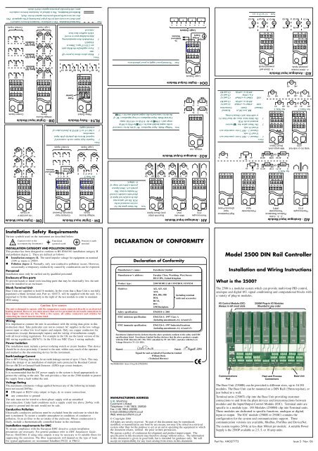
<strong>Model</strong> <strong>2500</strong> <strong>DIN</strong> <strong>Rail</strong> <strong>Controller</strong><br />
Installation and Wiring Instructions<br />
What is the <strong>2500</strong>?<br />
The <strong>2500</strong> is a modular system which can provide multi-loop PID control,<br />
analogue and digital I/O, signal conditioning and computational blocks with<br />
a variety of plug-in modules.<br />
I/O Control Module (IOC)<br />
Always in left most slots<br />
Communications<br />
Port<br />
<strong>2500</strong>M Plug-in I/O Modules<br />
Mounted in any order<br />
Plant and Process<br />
Connections<br />
Base Unit<br />
The Base Unit (<strong>2500</strong>B) can be provided is different sizes, up to 16 I/O<br />
modules. The Base Unit can be mounted on a <strong>DIN</strong> <strong>Rail</strong> (35mm top-hat), or<br />
just bolted to a wall.<br />
Terminal units (<strong>2500</strong>T) clip into the Base Unit providing customer<br />
connections to and from the plant devices and interconnections between<br />
modules and the Input/Output Control Module (IOC). Terminal units are<br />
specific to a module type. I/O Modules (<strong>2500</strong>M) clip into Terminal units.<br />
These modules are dedicated to specific functions, analogue or digital,<br />
input or output. The IOC module (<strong>2500</strong>E or <strong>2500</strong>C) contains the<br />
configuration for the system and communications support. Three<br />
communication versions are available, Modbus, Profibus and DeviceNet.<br />
The system requires 24Vdc at less than 100mA per module. A suitable Power<br />
Supply is the <strong>2500</strong>P available as 2.5, 5, or 10 amp units.<br />
Part No. HA027773 Issue 5 Nov. 06
The Base<br />
To mount the Base<br />
This unit is intended to be mounted within an enclosure, or in an environment suitable for<br />
IP20 rated equipment. It can be <strong>DIN</strong> rail or bulkhead mounted.<br />
(1) Retention Screws<br />
(2) Base Retention Clip<br />
(3) <strong>DIN</strong> <strong>Rail</strong><br />
(4) Side Cover<br />
(5) Terminal Unit<br />
Retention Clip<br />
(6) Support for Terminal<br />
Unit<br />
(7) EMC Earthing<br />
(8) Protective Earth<br />
Terminal Strip<br />
(* - Optional)<br />
Note<br />
Note<br />
Always ensure a<br />
25mm clearance<br />
for ventilation.<br />
(4)<br />
C<br />
D<br />
Only the 16 slot Base is unavailable.<br />
(6)<br />
(1)<br />
(2)<br />
E<br />
<strong>DIN</strong> <strong>Rail</strong> Mounting (horizontal)<br />
1 Mount the <strong>DIN</strong> rail horizontally, using suitable bolts.<br />
2 Ensure that the <strong>DIN</strong> rail makes good electrical contact with the metal base of the<br />
enclosure.<br />
3 Loosen screws (1) in the base, and allow them, and the associated base retention<br />
clips (2) to drop to the bottom of he screw slot.<br />
4 In the back of the base is an extruded slot which locates with the <strong>DIN</strong> rail(3).<br />
5 Fit the top edges of this into the top edge of the <strong>DIN</strong> rail (3). Slide the screws (1)<br />
with the associated clips (2) upwards as far as they will go towards the top of the<br />
screw slots. The angled edge of the base retaining clip (2) must locate behind the<br />
bottom edge of the <strong>DIN</strong> rail.<br />
6 Tighen the screws (1).<br />
<strong>DIN</strong> <strong>Rail</strong> Mounting (vertical)<br />
Caution<br />
It is acceptable to mount the base vertically. If it is mounted vertically, however, it is<br />
advisable to fit a fan in the cubicle to ensure a free flow of air around the modules.<br />
1 Mount the <strong>DIN</strong> rail vertically, using suitable bolts.<br />
2 Ensure that the <strong>DIN</strong> rail makes good electrical contact with the metal base of the<br />
enclosure.<br />
3 Loosen screws (1) in the base, and move them and the associated base retention<br />
clips (2) to the bottom of the screw slot.<br />
4 In the back of the base is an extruder slot which locates with the <strong>DIN</strong> rail (3)<br />
5 Fit the top edge of this into the top edge of the <strong>DIN</strong> rail (3)<br />
6 Slide the screws (1) with the associated clips (2) upwards as far as they will go<br />
towards the top of the screw slots. The angled edge of the base retaining clip (2)<br />
must locate behind the bottom edge of the <strong>DIN</strong> rail.<br />
7 Tighten the screws.<br />
Direct Panel Mounting<br />
1 Remove the screws (1) and base retention clips (2).<br />
2 Hold the base horizontally or vertically on the panel and mark the position of the<br />
two holes on the panel.<br />
3 Drill two 5.2mm holes in the panel.<br />
4 Using M5 bolts supplied, secure the base to the metal panel.<br />
A<br />
(8) (*8)<br />
(8)<br />
Module Dimensions Weight (kgms)<br />
Base A B C D E No Modules All Modules<br />
SO2 87 180 68 15 5 0.6 1.0<br />
SO4 137 180 68 15 5 0.6 1.0<br />
SO8 239 180 68 15 5 1.1 1.7<br />
S10 289 180 68 15 5 1.3 1.9<br />
S12 340 180 68 15 5 1.6 2.1<br />
S16 442 180 68 15 5 2.1 2.7<br />
(5)<br />
(7)<br />
(4)<br />
(3)<br />
(1)<br />
(2)<br />
(1)<br />
(2)<br />
B<br />
! Caution<br />
Do not operate the equipment without a protective earth conductor connected to one of the earth terminals<br />
on the base unit. The earth cable should have at least the current rating of the largest power cable used<br />
to connect to the unit.<br />
Connect the protective earth with a suitable tinned copper eyelet, and use the screw and washer<br />
supplied with the base unit, tightened to a torque of 1.2Nm (910.5lbin).<br />
This connection also provides a ground for EMC purposes.<br />
For <strong>DIN</strong> rail mounting, use symmetrical <strong>DIN</strong> rail to EN50022-35 X 7.5 or 35 X 15 mounted<br />
horizontally or vertically.<br />
Connecting the 24Vdc Power Supply<br />
Caution<br />
Before proceeding with any wiring on this unit, please read section on Wiring, and Safety and EMC<br />
information. It is the responsibility of the installer to ensure the safety and EMC compliance of any particular<br />
installation.<br />
The power supply is the <strong>2500</strong>P. This is a <strong>DIN</strong> rail mounted unit, which may be mounted adjacent to the base<br />
or remotely. Alternatively, an existing power supply may be used provided it meets the specification below.<br />
The IOC terminal unit contains a fuse and a reverse biased power diode. If the power is wired reverse polarity<br />
the fuse will blow and protect the complete base from damage. The fuse is not user replacable. The unit should<br />
be returned to the factory for replacement.<br />
POWER SUPPLY SPECIFICATION<br />
Power supply voltage: 18.0Vdc min to 28Vdc max<br />
Supply ripple: 2Vp-p max<br />
Power comsumption: 90W max per base<br />
Note The current taken by each module is 100mA on average. 18V is the absolute lower limit.<br />
The use of an 18V Power Supply with any appreciable voltage drop may cause unpredictable<br />
or out of specification operation.<br />
Software Upgrade Notification<br />
Caution<br />
The <strong>2500</strong> IOC version 3.6 and version 4.3 introduce additional fault action and sensor break detection<br />
parameters for Analogue Inputs.<br />
Take appropriate cautions when loading existing applications and carefully check Fault action responses.<br />
Assembling I/O Modules & Terminal Units<br />
To fit Terminal Unit<br />
Terminal Unit<br />
Terminal<br />
Retention clip<br />
Unit<br />
2<br />
To Fit a Module<br />
Base<br />
<strong>DIN</strong> <strong>Rail</strong><br />
Backplane<br />
Connector<br />
1<br />
EMC<br />
Earthing Strap<br />
Plant and Process<br />
Connections<br />
1 Locate tag on the Terminal Unit PCB<br />
with the slot in the Base Unit.<br />
2 Press the lower end of the Terminal<br />
Unit until secured in place by the<br />
Retention clip. This is indicated by a<br />
‘click’ as the clip locks into place.<br />
To remove simply press the<br />
Retention clip to release the Terminal<br />
Unit and withdraw it from the slot in<br />
the Base.<br />
Modules are locked into position using<br />
the Retaining lever on the face of the<br />
module.<br />
The module must be fitted and removed<br />
with the Retaining lever in the open<br />
( ) position, as shown in this side view.<br />
Once fitted the lever is closed to<br />
securely lock the module in place.<br />
The Configuration Port<br />
An RS232 configuration port is provided on the front of the IOC, via the RJ11 socket. The<br />
IOC will start in configuration mode when powered up with a PC connected to the RJ11<br />
socket . Alternatively, the IOC is put into configuration mode by setting a command from the<br />
configuration software.<br />
Note Exiting configuration mode must be done using LINtools or through communications.<br />
The IOC will not control the process if:<br />
• It is in configuration mode or standby mode<br />
• A network watchdog time-out occurs (if configured)<br />
• It is removed from the system<br />
Under these conditions all modules will enter a ‘safe’ state. Generally this defaults as digital<br />
output modules will go to an <strong>OF</strong>F state, and analogue output modules will go to a minimum<br />
output state (generally 0V or 4mA). Unless set otherwise in the configuration.<br />
Pin connections to this socket are given below:<br />
RJ11 into IOC 9-way D-Type into PC 25-way D-Type into PC<br />
6 no connection N/A N/A<br />
5 RX 3 TX 2 TX<br />
4 TCX 2 RX 3 RX<br />
3 0V 5 0V 7 0V<br />
2 no connection N/A N/A<br />
1 24V (in) N/A N/A<br />
Screen Screen 1 Screen<br />
Configuration Connections<br />
IOC Terminal unit Address Switches<br />
MODBUS PR<strong>OF</strong>IBUS DEVICENET<br />
8 7 6 5 4 3 2 1 8 7 6 5 4 3 2 1 8 7 6 5 4 3 2 1<br />
PO32168 4 21<br />
64 32 16 8 4 2 1 BAUD3216 8 4 2 1<br />
P E Modbus Addr.<br />
P = Parity on, P = Parity off,<br />
O = Odd, E = Even.<br />
63 Modbus addresses can<br />
be set in binary using<br />
positions 1 to 6.<br />
Parity has three possible<br />
states - none/even/odd -<br />
using SW7 and SW8.<br />
If the address switches are<br />
all set <strong>OF</strong>F, the IOC expects<br />
to have the address set by<br />
the configuration tools.<br />
For addresses between 65<br />
and 255 the address<br />
switches must all be set <strong>OF</strong>F<br />
and the address set by<br />
LINtools.<br />
Note<br />
Voltage<br />
Polarity Socket<br />
-<br />
+<br />
Optional Power Supply and<br />
cable for configuring the<br />
IOC remotely.<br />
24V Power<br />
Supply<br />
Switch Position On.<br />
Switch Position Off.<br />
PC used for<br />
configuration<br />
9-way<br />
connector<br />
<strong>2500</strong>A/CABLE/CONFIG/RJ11/9PINDF<br />
Profibus Addr.<br />
The switch gives 127<br />
addresses from 1 to 127.<br />
Address 0 is invalid.<br />
Switch 8 is not normally<br />
used. If, set to ON the<br />
unit address is settable<br />
over communications.<br />
ETHERNET<br />
8 7 6 5 4 3 2 1<br />
D O 3216 8 4 2 1<br />
D Modbus Unit ID<br />
D = DHCP enabled,<br />
D = DHCP disabled.<br />
6<br />
1<br />
IOC<br />
The plastic cover<br />
supplied must be<br />
fitted over the RJ11<br />
socket when NOT in<br />
use.<br />
On<br />
RATE DeviceNet Addr. Off<br />
The switch gives 64 addresses from<br />
0 to 63.<br />
SW7 SW8 Communications Speed<br />
1 0 125K Baud<br />
2 0 250K Baud<br />
3 0 500K Baud<br />
4 1 Both speed and node<br />
address controlled<br />
software<br />
Addresses 1 to 63 are set on the<br />
rightmost 6 switches.<br />
The leftmost switch may be used to<br />
enable DHCP Ethernet addressing.<br />
If all switches are <strong>OF</strong>F, the Modbus<br />
address and DHCP enable will be<br />
determined by the value seen in<br />
LINtools.<br />
Modbus Communications<br />
The Modbus network connection<br />
(RJ45 sockets) and the system<br />
power connections (standard<br />
screw terminals) are provided<br />
by the Terminal Unit.<br />
The network connection to an<br />
operator interface unit, a PC<br />
running LINtools or 3rd party<br />
system, or to link further slave<br />
controllers or other Modbus<br />
equipment in a system. The IOC<br />
can be configured from the<br />
Modbus network if required.<br />
+24V 0V<br />
Modbus RJ45 Pin Connections to Network Connectors<br />
RJ45 Pin Colour EIA485 2-wire 4-wire<br />
1 Orange/White B D- TX-<br />
2 Orange A D+ TX+<br />
3 Green/White Gnd Gnd Gnd<br />
4 Blue N/A N/A N/A<br />
5 Blue/White N/A N/A N/A<br />
6 Green Gnd Gnd Gnd<br />
7 Brown/White B N/A RX-<br />
8 Brown A N/A RX+<br />
Screen N/A N/A N/A N/A<br />
CABLE COLOURS MAY CHANGE!<br />
LED status<br />
indicators<br />
Configuration<br />
port (RS232)<br />
Warning<br />
Modbus - RJ45 Communications Line Terminator<br />
The communications line must be terminated using the appropriate load resistors. To<br />
minimise on site wiring and to provide the correct resistor values, ‘Terminator’ are<br />
available from your distributor.<br />
Term/Modbus/RJ45<br />
Modbus - Black<br />
Moulding colour<br />
Module<br />
connector<br />
422/485<br />
Jumpers<br />
Address<br />
switches<br />
Communications<br />
ports (RS485)<br />
Profibus DP and DPv1 Communications<br />
Connections to the Network Connectors<br />
There are two ProfiBus TU<br />
options: a standard 9-Way LED status<br />
indicators<br />
D-type, and a dual RJ45 unit.<br />
The latter is similar to the<br />
Modbus terminal unit, but<br />
must not be confused; the<br />
Modbus unit includes<br />
capacitors that could affect Configuration<br />
port (RS232)<br />
high-speed data.<br />
Baud rate<br />
Baud rate is set by the Profibus<br />
Master which is able to detect<br />
the fastest Baud at which all<br />
slaves can operate. The<br />
Profibus IOC is capable of<br />
operating at 12Mbaud.<br />
Communications<br />
ports (RS485)<br />
+24V 0V<br />
+24V 0V<br />
Profibus - 9-way D-Type Pin Connections to Network Connectors<br />
9 Pin D-Type Signal Name Meaning<br />
1 Shield Shield (ground)<br />
2 Not Used N/A<br />
3 RxD/TxD-P Receive/Transmit - Data ‘P’<br />
4 Not Used N/A<br />
5 DGND Data Ground<br />
6 VP Voltage Plus<br />
7 Not Used N/A<br />
8 RxD/TxD-N Receive/Transmit - Data ‘P’<br />
9 Not Used N/A<br />
Profibus - 9-way D-Type Communications Line Terminator<br />
For 9 pin D connectors standard ProfiBus cables should be used. These cables have<br />
special headers on the 9 pin D male connector which allow one or two cables to be<br />
connected into them and have a small termination load built in with an ON/<strong>OF</strong>F switch,<br />
which is set to ON at the two ends of the link.<br />
The ProfiBus standard states that two types of cable, ‘Line A’ and ‘Line B’, may be<br />
used. The termination details for these two types of cable are shown below:<br />
Module<br />
connector<br />
Communications<br />
Line Terminator<br />
Address<br />
switches<br />
9-way D-Type<br />
Communications<br />
connector<br />
Profibus - RJ45 Pin Connections to Network Connectors<br />
RJ45 Pin Colour Signal<br />
1 Orange/White Date ‘N’<br />
2 Orange Date ‘P’<br />
3 Green/White Gnd<br />
4 Blue N/A<br />
5 Blue/White N/A<br />
6 Green +15V<br />
7 Brown/White N/A<br />
8 Brown N/A<br />
Term/Profibus/RJ45<br />
8<br />
1<br />
Label<br />
DeviceNet Communications<br />
The DeviceNet Communications IOC is<br />
identified by the front label and the order<br />
code printed on the side label. This IOC<br />
must be used with the DeviceNet Terminal<br />
Unit.<br />
The DeviceNet Connector is selected to<br />
comply with the DeviceNet Open<br />
Connector specification (5-way, 5.08mm<br />
pitch).<br />
Module<br />
connector<br />
Profibus - Grey<br />
Moulding colour<br />
PR<strong>OF</strong>I<br />
8<br />
1<br />
180Ω 5%<br />
180Ω 5%<br />
130Ω 5%<br />
Ethernet Communications<br />
The Ethernet Communications IOC is<br />
identified by the front label and the<br />
order code printed on the side label.<br />
This IOC must be used with the<br />
Ethernet Terminal Unit.<br />
The Ethernet port is a 10base T port<br />
and can be connected to a hub or switch<br />
with Cat5 cable via the standard RJ45<br />
connector. Alternatively, an RJ45<br />
cross-over cable may be used to connect<br />
direct to a PC 10base T network<br />
Interface Card.<br />
8<br />
1<br />
Label<br />
MB120<br />
AN100<br />
120Ω 5%<br />
120Ω 5%<br />
120Ω 5%<br />
The terminator is plugged into the last RJ45 socket in the chain. If the operating<br />
interface is a PC or PLC this should be terminated in accordance using the appropriate<br />
load resistors.<br />
RS422-RS485 Modbus communications selection<br />
LK1<br />
1<br />
Module Address<br />
Switch<br />
LK2<br />
1<br />
8<br />
1<br />
Fit both links:<br />
1 - 2 for 2 (3) wire (default)<br />
2 - 3 for 4 (5) wire<br />
Note<br />
Earlier units were fitted with a<br />
single link for 2(3) wire or no link<br />
for 4(5) wire.<br />
Fit suitable termination ONLY on the last<br />
device in the chain.<br />
The use of the termination plug is<br />
recommended.<br />
5 8 3 6<br />
390Ω 220Ω 390Ω<br />
Profibus Line A<br />
5 8<br />
390Ω 150Ω 390Ω<br />
Profibus - RJ45 Built-in Communications Line Terminator<br />
LK1<br />
1<br />
Module Address<br />
Switch<br />
LK2<br />
1<br />
Fit both links:<br />
1 - 2 to terminate the Profibus network<br />
2 - 3 no termination<br />
Note<br />
Profibus Line B<br />
Earlier units were fitted with a<br />
single link. On these units this<br />
link has no function and the<br />
system should be terminated<br />
using the termination plug.<br />
Fit suitable termination ONLY on the last<br />
device in the chain.<br />
On earlier units the use of the termination<br />
plug is recommended. On later units fit<br />
either the termination unit, or place both<br />
links in position 1 & 2.<br />
6<br />
+24V 0V<br />
Address<br />
switches<br />
5<br />
4<br />
3<br />
2<br />
1<br />
5-way<br />
Communications<br />
connector<br />
24V Power<br />
supply terminals<br />
The mating DeviceNet connector (female<br />
Open Connector) is supplied to facilitate<br />
screwing user wiring. The pin functions are<br />
marked on the Terminal Unit.<br />
Connections to Network Connectors<br />
Pin Function<br />
1 V+<br />
2 CAN_H<br />
3 DRAIN<br />
4 CAN_L<br />
5 V-<br />
DeviceNet Terminators<br />
The DeviceNet specification states that the<br />
bus terminators should not be included as<br />
any part of a master or slave. They are not<br />
supplied as part of the DeviceNet<br />
termination assembly.<br />
Module<br />
connector<br />
Address<br />
switches<br />
RJ45 socket<br />
24V Power<br />
supply terminals<br />
Connections to RJ45 Socket<br />
RJ45 Pin Colour Signal<br />
1 Orange/White TX+<br />
2 Orange TX-<br />
3 Green/White RX+<br />
4 Blue N/A<br />
5 Blue/White N/A<br />
6 Green RX-<br />
7 Brown/White N/A<br />
8 Brown N/A<br />
Warning<br />
CABLE COLOURS MAY CHANGE!