T750 Adapter Sleeve Product Specification - d a n m a r k
T750 Adapter Sleeve Product Specification - d a n m a r k
T750 Adapter Sleeve Product Specification - d a n m a r k
- No tags were found...

Create successful ePaper yourself
Turn your PDF publications into a flip-book with our unique Google optimized e-Paper software.
NETWORK6000EUROTHERMPRO ESSAUTOMATIONε10T640ε1080T640<strong>T750</strong>8060PV-X6040PV-XOUT-Y<strong>Adapter</strong> sleeveOUT-Y4020R A AM0%PV-X SP-TINS R A??ALM SP-W M20R A AM0%PV-X SP-WTINS R A??ALM SP-W M<strong>Product</strong>1specification
1010806040200%PV-X SP-WSP-W●T640 plugs directly into 7950 rack●Electrically compatible with 6350/60/66/70/80/82●Long-term support for your TCS controller●T640 plugs into 7910 and 7911 adapter sleeveGeneralThe <strong>T750</strong> adapter sleeve allows aT640 to be plugged directly into a7950 rack. A T640 in a <strong>T750</strong> sleevehas the same physical structure(dimensions and connectors) and thesame I/O allocation as the 6350/60/66/70/80/82 and other members ofthe 6000 controller family with thesame pinout.The <strong>T750</strong> is designed to supportyour investment in the 6000instrument series by using existingspare slots or upgrading thefunctionality to that of T640s.In emulating 6000 instruments someof the T640’s own functionality isrestricted. This occurs because theT640 in a T710 sleeve has a largerpinout. The main restrictions are theloss of the alarm relay and the secondisolated transmitter power supply.The following features have beenretained with some modification:Second isolated 0-20mA outputAs supplied this output is notavailable; however two jumpers (P15& P16) in the <strong>T750</strong> may bepositioned so that this outputreplaces AN3.OUT and AN4.OUT.If this option is chosen the TA637X/8X should be used as AN4.OUT isnot available on TA635X/6X.ALIN This communication channelis fundamental to the T640 and it istherefore brought out on pins 4, 5and 6. As the pins were formerlyunused, spills and connectors aresupplied with the <strong>T750</strong> to allowconnection.RS422/485 The T640 isolates thiscommunications port. The <strong>T750</strong>connects the common signal toground in order to emulate the 6000instruments.Power Supply The 6000instruments only support 24 voltpower supplies, a mains option beingavailable in the 7950 sleeve. Whenselecting a T640 for use in a <strong>T750</strong>the DC option must be specified sothat it receives its power in the samemanner.The <strong>T750</strong> may be used with 7910and 7911 adapter sleeves. However,because of the enclosed nature ofthese sleeves the maximum ambienttemperature is derated to 40°C.Special provision must also be madefor giving access to the ALINconnections, if required.Watchdog This output is suppliedin the form of volt-free contactswithin the T640. The <strong>T750</strong> modifiesthis to a logic output to emulate the6000 instruments.ε806040200%PV-X SP-T640PV-XOUT-YR A AMTεINS R??ALMT640PV-XOUT-YR A AMTAMINS??RAALMSP-WM2
<strong>T750</strong> PIN CONNECTIONS<strong>T750</strong>PIN NoTA637X/8XTERMINAL No637X/8XINSTRUMENT FUNCTIONTA635X/6XTERMINAL No6350/60INSTRUMENT FUNCTIONT640FUNCTIONSITECHBIT1237891416,17,18,19432815130 VOLTS SUPPLY0 VOLTS ANALOGUE0 VOLTS DIGITALDIG OUT. DC. P/UPDC SUPPLY I/PWATCH DOG OUT 116,17,18,1914,34,431513,280 VOLTS REFERENCE0 VOLTS POWER ♦DC SUPPLY I/PWATCH DOG OUT 1DC — POWER IN 1ANALOGUE GNDDIGITAL GROUNDEXT SUPPLY IN 24 VOLTSDC + POWER IN 1WATCHDOG1011121314151617181920212223242526271234313220212223242526275678AN1. INAN2. INAN3. INAN4. INAN5. IN *AN6. IN *DIG1. OUTDIG2. OUTDIG3. OUTDIG4. OUTDIG5. OUTDIG6. OUTDIG7. OUTDIG8. OUTDIG1. INDIG2. INDIG3. INDIG4. IN12331323320212223242526275678PV. IN (1 - 5V)REM. SP. IN (1 - 5V)SP. TRIM IN (1 - 5V)PV. IN (0 - 10V)REM. SP. IN (0 - 10V)SP. TRIM IN (0 - 10V)HI. ALM. OUT (0)LO. ALM. OUT (0)HW. ALM. OUT (0)BAT. LOW OUT (0)REM. AUT. OUT (0)HLD + MAN. OUT (0)BIT 1 OUT (1)BIT 2 OUT (1)ADD1 IN (1)ADD2 IN (1)ADD4 IN (1)ADD8 IN (1)ANALOGUE INPUTANALOGUE INPUTANALOGUE INPUTANALOGUE INPUTANALOGUE INPUTANALOGUE INPUTDIGITAL OUTPUTDIGITAL OUTPUTDIGITAL OUTPUTDIGITAL OUTPUTDIGITAL OUTPUTDIGITAL OUTPUTDIGITAL OUTPUTDIGITAL OUTPUTDIGITAL INPUTDIGITAL INPUTDIGITAL INPUTDIGITAL INPUT111122111122221111123412012301230123282930319101112DIG5. INDIG6. INDIG7. INDIG8. IN9101112COMP. EN. IN (1)REM. SP. EN. IN (1)TRACK EN. IN (1)HOLD EN. IN (0)DIGITAL INPUTDIGITAL INPUTDIGITAL INPUTDIGITAL INPUT2222012332333738AN1. OUTAN2. OUT40383T OUT (0 - 10V)PV OUTANALOGUE OUTPUTANALOGUE OUTPUT11123439AN3. OUT39SP/DEV OUTANALOGUE OUTPUT213536373829304445XMT. OUT (—) RS422XMT. OUT (+) RS422RCV. IN (—) RS422RCV. IN (+) RS42229304445XMT. OUT (—) RS422XMT. OUT (+) RS422RCV. IN (—) RS422RCV. IN (+) RS422RS422 TX —RS422 TX +RS422 RX —RS422 RX +3940AN4. OUTANALOGUE OUTPUT2240413536TX. SUPPLY (—)TX. SUPPLY (+)3536TX. SUPPLY (—)TX. SUPPLY (+)TX POWER SUPPLY —TX POWER SUPPLY +4345474841423334ABCOS4 ISOL (—)OS4 ISOL (+)AN7. INAN8. IN**DC SUPP1 IN (20 - 30V)24V SUPP OUTDC SUPP2 IN (20 - 30V)4142ABC3T. OUT ISOL 4 - 20mA (—)3T. OUT ISOL 4 - 20mA (+)DC SUPP1 IN (20 - 30V)24V SUPP OUTDC SUPP2 IN (20 - 30V)CURRENT OUTPUT —CURRENT OUTPUT +ANALOGUE INPUTANALOGUE INPUT11223334456ALIN GNDALIN PHASE AALIN PHASE BALIN GNDALIN PHASE AALIN PHASE B* Not available with 6370/80 models♦ For 6350/60 fit P17 to Pins 1-2The <strong>T750</strong> connects the RS422 GND to DIGITAL GROUNDWhen 2nd current option is selected the following applies3439394039N/CCURRENT OUTPUT —CURRENT OUTPUT +22333
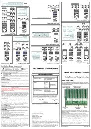
INSTALLATIONTo install the <strong>T750</strong> sleeve:If required assemble ALIN system connector spills in positions 4,5 and 6 of the system connector. Holding the spill by the wirewrap tail, with the spill correctly orientated, insert into theconnector housing. Wire ALIN connections using Faston crimpterminals supplied.Connector spills to beassembled in positions 4, 5and 6 for ALIN connections216510141691317Spill orientationfor position 52221Spill orientationfor positions4 and 62529Module guide barsCross rail<strong>T750</strong> <strong>Adapter</strong> sleevePerforated cover(part view)(optional)Cross rail48-way socketSide angleCable trunking16-way terminalblocksSide plateRear-mountedpower supply(8750)Rear termination panelCable tray/gland plate(CGP option)Hinge-down cover(CGP option)4
INSTALLATION (continued)Link settingsCheck that the links within the <strong>T750</strong> are correctly set.Links P15 and P16 P171-2 Pins 34 and 39 are 0 volts supply is linkedconnected to the internally to 0 voltssecond isolateddigitalanalogue output2-3 * Pin 34 and 39 are Power supply inputnon-isolatedisolatedvoltage outputs.* Factory setting is 2-3 for all linksFor instrument emulation:Instrument P15 and P16 P17635x and 636x 2-3 1-2637x and 638x 2-3 2-3Insert the <strong>T750</strong> sleeve into the empty housing/slot by lining upthe sleeve with the guide rails and sliding the sleeve home untilthe system connector mates fully with the termination assembly.Note. When handling the T640 Controller anti-static precautionsmust be observed.15P13P15101520253035637x / 638x3403 3P17 1635x / 636x2Voltage Output63xxP15082968 IssT640 / 7950 <strong>Adapter</strong> Micro Connector PCBCurrent Output451 1P281 P280353025201510511151Insert the T640 Controller into the <strong>T750</strong> sleeve by lining up theT640 printed circuit boards with the <strong>T750</strong> board guides andsliding the unit home until the edge connectors fully mate.Lock the T640 into the sleeve by sliding the locking catches atthe top and bottom of the T640 front panel to the lockedposition. (See T640 User Guide)<strong>T750</strong> <strong>Adapter</strong> sleeveRemoval of <strong>T750</strong> sleeveUnlock the T640 controller by sliding the locking catches at thetop and bottom of the T640 front panel to the unlocked position.(See the T640 User Guide).Using the T640 extractor key located in the front panel (SeeT640 User Guide) withdraw the T640 Controller from the <strong>T750</strong>sleeve.<strong>Sleeve</strong> retainingcatchLift the sprung <strong>T750</strong> retaining catch and withdraw the <strong>T750</strong>from the host housing.Lift sleeve retainingcatch and withdrawsleeve from host housing5
SPECIFICATION for T640 in <strong>T750</strong> sleeveEnvironmentalStorage temperature: –10°C to +85°COperating temperature: 0°C to +50°CRFI emissions:To meet EN55022 Class BRFI susceptibility: To meet IEC801 Parts 2-4, acceptability Class 2Instrument safety:To meet BS4743 Class IIIsolation:To meet BS4743, with isolated I/O as Class IIPower supplyInput voltage range:Power rating:Hold up time:Fuse:19 to 55V DC (includes rectified 48V AC rms)25VA20ms20 × 5 mm 250V AC anti-surge cartridge, 2AAnalogue inputsChannels: 8Input ranges:0-5V and 0-10V, with software-selectable range0-1.25 V range is jumper selectable but all inputsand voltage outputs take on this rangeResolution: 0.025%Accuracy: 0.05%Gain drift:30ppm/°COffset drift65µV/°CInput impedance:1MΩ pull-down to -1.2VBreak detection:Within one sample. Protection strategy selectedfrom within the configuration (e.g. up-scale,down-scale)Isolation:NoneSample rate:9ms per configured input. Only the configuredinputs are scanned. The fastest loop updatecannot be less than 20msTransmitter power suppliesChannels: 1Voltage: 24V (± 5%)Current:22mACurrent limit:30mA maxIsolation:60V workingVoltage analogue outputsChannels:4 (see note)Input ranges:0-5V and 0-10V, with software-selectable range0-1.25 V range is jumper selectable but all inputsand voltage outputs take on this rangeResolution:12 bits - 1.25mV on 5V range and 2.5mV on10V rangeAccuracy: 0.05%Gain drift:30ppm/°COffset drift:70µV/°CCurrent drive:± 5 mAOverload detection:Triggered if the output cannot obtain the desiredvalue.Isolation:NoneCurrent analogue outputsChannels:1 (see note)Input ranges:0-20mA (Software rangeable to 0-10mA,4-20mA etc.)Resolution: 5µAAccuracy: 0.1%Gain drift:80ppm/°COffset drift:0.9µA/°COutput Drive:0-1kΩIsolation:60V workingDigital inputsChannels: 8Thresholds:Logic 1: –7.5V maximumLogic 0: –3.5V minimumHysteresis:1.0V minimum3.5V maximumInput voltage:28V maxInput Impedance: 200kΩ for inputs 10VExternal supply(DC pull-up)If used this input will set the pull-up voltages forthe DIGITAL OUTPUTS and the WATCHDOGOUTPUT. If not the internal supply is usedMin voltage 15.5VMax voltage 28VMin current 120mADigital outputsChannels: 8Output levels:Logic 0:- 0VLogic 1:- 15V (14 to 15.5V with internal supply,or equal to external supply -1.4V)Drive impedance:Logic 0: 68Ω, 37mA absolute maxLogic 1: 2.2kΩWatchdog outputWatchdog fail:Watchdog OK:ALINCable type:Impedance:Network topology:Network terminations:Maximum load:Maximum length:Isolation:Grounding:High impedance2.7kΩ pull-up to 15V or direct connection toexternal supplyScreened twisted pair82Ω nominalSingle non-branching network82Ω at each end20 nodes100 meters60V workingSingle point ground per systemRS422Transmission standard: RS422/485 (selectable)Cable type:Twisted pairImpedance: 120-240ΩMaximum load: 16Maximum length:1200m (at 9600 baud)Baud rate:300, 1200, 4800, 9600 (Software selectable)Protocol:Binary or ModbusGrounding:Connected internally to digital groundNote.A second isolated current loop output is jumper-link selectable. Theconnections used replace two of the voltage analogue outputs.6
ORDERING INFORMATION<strong>T750</strong> Order codeThe <strong>T750</strong> may be ordered on its own as <strong>T750</strong>. There are no options.BaseUnit<strong>T750</strong>ExampleBase Unit<strong>T750</strong> <strong>Adapter</strong> sleeveCode<strong>T750</strong>Alternatively the <strong>T750</strong> may be specified as part of the T640 order code replacing the T710.NotesBase Power Serial Site 1 Site 2 Memory Calibration Config LabellingUnit Supply Comms I/O Board I/O Board Module <strong>Sleeve</strong> Certificate Sheet LanguageT640 DC 422 HI HI M002 <strong>T750</strong> — — ENExample1. Only the T640/DC option is compatible with the <strong>T750</strong>2. Both 422 and 485 options are available but 422 must be specified to emulate 6000 instruments3. Only the HI I/O options are supported by <strong>T750</strong>4. All memory modules are supported7
εT640ε10T6401080PV-X8060PV-XOUT-Y604040OUT-Y20R A AM0%PV-X SP-WT20R A AMINS??RA0%PV-X SP-TALMSP-WMINS??ALMRSP-WAMEUROTHERM PROCESS AUTOMATION LIMITEDSOUTHDOWNVIEW WAY, WORTHING, WEST SUSSEX BN14 8NNTELEPHONE: +44 (0) 1903 205277 FAX: +44 (0) 1903 233902 TELEX: 87437HA 082520U 001Issue 1/A June 1994© 1994 Eurotherm Process Automation Limited. All Rights Reserved.Eurotherm Process Automation continuously strives to improve and develop its products. The specifications in this document may therefore be changed without notice.