SHORTSTOPP® Welding Fittings - T.D. Williamson, Inc.
SHORTSTOPP® Welding Fittings - T.D. Williamson, Inc.
SHORTSTOPP® Welding Fittings - T.D. Williamson, Inc.

Create successful ePaper yourself
Turn your PDF publications into a flip-book with our unique Google optimized e-Paper software.
SHORTSTOPP® <strong>Welding</strong> <strong>Fittings</strong><br />
Sizes: 1-1/4- through 12-inch<br />
Bulletin No: 2100.003.03<br />
Date: September 2005<br />
Cross Indexing No: n/a<br />
Supersedes: 2100.003.02 (10/02)<br />
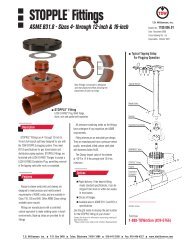
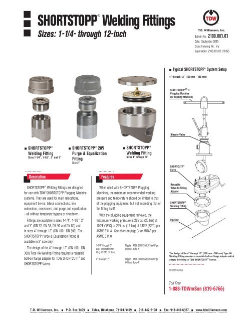
Typical SHORTSTOPP ® System Setup<br />
4” through 12” (100 mm - 300 mm)<br />
SHORTSTOPP ® II<br />
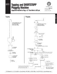
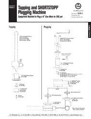
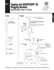
Plugging Machine<br />
(or Tapping Machine)<br />
Bleeder Valve<br />
SHORTSTOPP ®<br />
<strong>Welding</strong> Fitting<br />
Sizes 1-1/4”, 1-1/2”, 2” and 3”<br />
SHORTSTOPP ® 285<br />
Purge & Equalization<br />
Fitting<br />
Size 2”<br />
SHORTSTOPP ®<br />
<strong>Welding</strong> Fitting<br />
Sizes 4” through 12”<br />
SHORTCUTT ®<br />
Valve<br />
Description<br />
Features<br />
SHORTSTOPP ® <strong>Welding</strong> <strong>Fittings</strong> are designed<br />
for use with TDW SHORTSTOPP Plugging Machine<br />
systems. They are used for main relocations,<br />
equipment tie-ins, lateral connections, line<br />
extensions, crossovers, and purge and equalization<br />
– all without temporary bypass or shutdown.<br />
<strong>Fittings</strong> are available in sizes 1-1/4”, 1-1/2”, 2”<br />
and 3” (DN 32, DN 38, DN 50 and DN 80) and<br />
in sizes 4” through 12” (DN 100 - DN 300). The<br />
SHORTSTOPP Purge & Equalization Fitting is<br />
available in 2” size only.<br />
The design of the 4” through 12” (DN 100 - DN<br />
300) Type IIA <strong>Welding</strong> Fitting requires a reusable<br />
bolt-on flange adapter for TDW SHORTCUTT ® and<br />
SHORTSTOPP Valves.<br />
When used with SHORTSTOPP Plugging<br />
Machines, the maximum recommended working<br />
pressure and temperature should be limited to that<br />
of the plugging equipment, but not exceeding that of<br />
the fitting itself.<br />
With the plugging equipment removed, the<br />
maximum working pressure is 285 psi (20 bar) at<br />
100ºF (38ºC) or 245 psi (17 bar) at 180ºF (82ºC) per<br />
ASME B31.4. See chart on page 3 for MOAP per<br />
ASME B31.8.<br />
1-1/4” through 3” Nipple: A106 GR B SMLS Steel Pipe<br />
Cap: Malleable Iron O-Ring: Buna-N<br />
Plug: C1213 CF Steel<br />
4” through 12” Nipple: A106 GR B SMLS Steel Pipe<br />
O-Ring: Buna-N<br />
Reusable<br />
Valve-to-Fitting<br />
Adapter<br />
SHORTSTOPP ®<br />
<strong>Welding</strong> Fitting<br />
Pipeline<br />
The design of the 4” through 12” (100 mm - 300 mm) Type IIA<br />
<strong>Welding</strong> Fitting requires a reusable bolt-on flange adapter which<br />
adapts the fitting to TDW SHORTCUTT ® Valves.<br />
ISO 9001 Certified<br />
Toll Free<br />
1-888-TDWmSon (839-6766)<br />
T.D. <strong>Williamson</strong>, <strong>Inc</strong>. P.O. Box 3409 Tulsa, Oklahoma 74101-3409 918-447-5100 Fax: 918-446-6327 www.tdwilliamson.com<br />
Data subject to change without notice. / Dimensions not for construction unless certified. / ® Registered trademark of T.D. <strong>Williamson</strong>, <strong>Inc</strong>. in the United States and foreign countries / TM Trademark of T.D. <strong>Williamson</strong>, <strong>Inc</strong>. in the United States and foreign countries / © Copyright 2009. All rights reserved T.D. <strong>Williamson</strong>, <strong>Inc</strong>. / Printed in USA
Dimensions and Part Numbers<br />
SHORTSTOPP ® <strong>Welding</strong> <strong>Fittings</strong><br />
2100.003.03 - p2<br />
L<br />
L<br />
L<br />
1-1/4” through 3”<br />
2” only<br />
4” through 12”<br />
1-1/4” through 3”<br />
<strong>Welding</strong> fitting includes<br />
cap, completion plug,<br />
O-ring and nipple.<br />
2” only<br />
Purge & Equalization fitting<br />
includes cap, completion<br />
plug, O-ring and nipple.<br />
4” through 12”<br />
<strong>Welding</strong> fitting includes<br />
cover flanges with bolts,<br />
gasket and plastic caplugs,<br />
completion plug, O-ring and<br />
flanged nipple.<br />
Dimensions<br />
Size<br />
L<br />
<strong>Inc</strong>hes DN <strong>Inc</strong>hes mm<br />
1-1/4 32 2-5/16 75<br />
1-1/2 38 3 80<br />
2 50 3 80<br />
2 (flat) 50 3-7/16 88<br />
3 80 3-7/8 98<br />
4 100 4-3/8 111<br />
6 150 5-3/16 132<br />
8 200 5-5/16 135<br />
10 250 6 152<br />
12 300 6 152<br />
3 x 4 80 x 100 3-7/8 98<br />
4 x 6 100 x 150 4-3/8 111<br />
6 x 8 150 x 200 5-3/16 132<br />
8 x 10 200 x 250 5-5/16 135<br />
8 x 12 200 x 300 5-5/16 135<br />
Valve-to-Fitting Adapters for 4” through 12”<br />
Size<br />
Weight<br />
<strong>Inc</strong>hes DN Lbs. Kg. Part Number<br />
4 100 10 5 06-5724-0001<br />
6 150 13 6 06-5724-0002<br />
8 200 25 11 06-5724-0003<br />
10 250 40 18 06-5724-0010<br />
12 300 55 25 06-5724-0011<br />
4 x 6 100 x 150 18 8 06-5724-0007<br />
6 x 8 150 x 200 28-1/2 13 06-5724-0004<br />
8 x 10 200 x 250 44 20 06-5724-0009<br />
10 x 12 250 x 300 70 32 06-5724-0012<br />
The 4” x 6”, 6” x 8”, 8” x 10” and 10” x 12” adapters are used to adapt the valve to the next smaller fittings.<br />
T.D. <strong>Williamson</strong>, <strong>Inc</strong>. P.O. Box 3409 Tulsa, Oklahoma 74101-3409 918-447-5100 Fax: 918-446-6327 www.tdwilliamson.com<br />
Data subject to change without notice. / Dimensions not for construction unless certified. / ® Registered trademark of T.D. <strong>Williamson</strong>, <strong>Inc</strong>. in the United States and foreign countries / TM Trademark of T.D. <strong>Williamson</strong>, <strong>Inc</strong>. in the United States and foreign countries / © Copyright 2009. All rights reserved T.D. <strong>Williamson</strong>, <strong>Inc</strong>. / Printed in USA
Dimensions and Part Numbers<br />
SHORTSTOPP ® <strong>Welding</strong> <strong>Fittings</strong><br />
2100.003.03 - p3<br />
SHORTSTOPP ® <strong>Welding</strong> <strong>Fittings</strong> for Use with SHORTSTOPP ® 60, SHORTSTOPP ® II and SHORTSTOPP ® 275 Plugging Machines<br />
Maximum allowable operating pressure (in psi) per ASME B31.8 at -20 to +100º F<br />
Size Weight Design Factor<br />
<strong>Inc</strong>hes DN Lbs. Kg. Part Number 0.72 0.6 0.5 0.4<br />
1-1/4 32 1-1/2 0.7 06-1179-0000 285 285 285 285<br />
1-1/2 38 2 0.9 26-0211-0000 285 285 285 285<br />
2 50 2.5 1.1 26-0212-0000 285 285 285 285<br />
2 (flat) 50 2 0.9 26-0319-0000 (no bevel) 285 285 285 285<br />
3 80 3.5 1.6 26-0213-0000 285 285 285 285<br />
4 100 18 8 06-7213-0000 285 285 285 285<br />
6 150 40 18 06-7214-0000 285 285 285 285<br />
8 200 64 29 06-7215-0000 285 285 285 275<br />
10 250 120 54 06-7216-0000 285 285 285 240<br />
12 300 165 75 06-7217-0000 285 285 275 220<br />
3 x 4 80 x 100 3.5 1.6 26-0324-0000 285 285 285 250<br />
4 x 6 100 x 150 18 8 06-9541-0000 285 285 285 285<br />
6 x 8 150 x 200 40 18 06-9542-0000 285 285 285 280<br />
8 x 10 200 x 250 64 29 06-9543-0000 285 285 285 245<br />
8 x 12 200 x 300 64 29 06-9544-0000 285 285 285 225<br />
Minimum Pipe Wall Thicknesses (<strong>Inc</strong>hes)<br />
Size Header Design Factor Min. Pipe Wall Thickness<br />
<strong>Inc</strong>hes Pipe OD .0.72 0.60 0.50 0.40<br />
1-1/4 1.660 0.019 0.023 0.027 0.034<br />
1-1/2 1.900 0.021 0.026 0.031 0.039<br />
2 (incl. flat) 2.375 0.027 0.032 0.039 0.048<br />
3 3.500 0.040 0.048 0.057 0.071<br />
4 4.500 0.051 0.061 0.073 0.092<br />
6 6.625 0.075 0.090 0.108 0.135<br />
8 8.625 0.098 0.117 0.140 0.176<br />
10 10.750 0.122 0.146 0.175 0.219<br />
12 12.750 0.144 0.173 0.208 0.260<br />
3 x 4 4.500 0.051 0.061 0.073 0.092<br />
4 x 6 6.625 0.075 0.090 0.108 0.135<br />
6 x 8 8.625 0.098 0.117 0.140 0.176<br />
8 x 10 10.750 0.122 0.146 0.175 0.219<br />
8 x 12 12.750 0.144 0.173 0.208 0.260<br />
Note: The TDW fitting provides sufficient material wall thickness for itself and<br />
in many cases reinforcement for the branch opening in the pipe. However, the<br />
chart above specifies minimum wall thickness of the pipe for self reinforcment.<br />
(Based on 35,000 PSI SMYS)<br />
Spare O-Rings & Gaskets<br />
Size Spare O-Rings Spare Gaskets<br />
<strong>Inc</strong>hes DN Part Number Part Number<br />
1-1/4 32 00-0117-0014 --<br />
1-1/2 38 00-0117-0010 --<br />
2 (incl. flat) 50 00-0117-0010 --<br />
3 80 00-0117-0013 --<br />
4 100 00-1250-0001 00-5238-0004-01<br />
6 150 00-1250-0002 00-5238-0006-01<br />
8 200 00-1250-0003 00-5238-0008-01<br />
10 250 00-1250-0004 00-5238-0010-01<br />
12 300 00-1250-0005 00-5238-0012-01<br />
3 x 4 80 x 100 00-0017-0013 --<br />
4 x 6 100 x 150 00-1250-0001 00-5238-0004-01<br />
6 x 8 150 x 200 00-1250-0002 00-5238-0006-01<br />
8 x 10 200 x 250 00-1250-0003 00-5238-0008-01<br />
8 x 12 200 x 300 00-1250-0003 00-5238-0008-01<br />
T.D. <strong>Williamson</strong>, <strong>Inc</strong>. P.O. Box 3409 Tulsa, Oklahoma 74101-3409 918-447-5100 Fax: 918-446-6327 www.tdwilliamson.com<br />
Data subject to change without notice. / Dimensions not for construction unless certified. / ® Registered trademark of T.D. <strong>Williamson</strong>, <strong>Inc</strong>. in the United States and foreign countries / TM Trademark of T.D. <strong>Williamson</strong>, <strong>Inc</strong>. in the United States and foreign countries / © Copyright 2009. All rights reserved T.D. <strong>Williamson</strong>, <strong>Inc</strong>. / Printed in USA
2100.003.03 - p4<br />
T.D. <strong>Williamson</strong>, <strong>Inc</strong>. P.O. Box 3409 Tulsa, Oklahoma 74101-3409 918-447-5100 Fax: 918-446-6327 www.tdwilliamson.com<br />
Data subject to change without notice. / Dimensions not for construction unless certified. / ® Registered trademark of T.D. <strong>Williamson</strong>, <strong>Inc</strong>. in the United States and foreign countries / TM Trademark of T.D. <strong>Williamson</strong>, <strong>Inc</strong>. in the United States and foreign countries / © Copyright 2009. All rights reserved T.D. <strong>Williamson</strong>, <strong>Inc</strong>. / Printed in USA