

History of Ericsson - ericssonhistory.com
History of Ericsson - ericssonhistory.com
History of Ericsson - ericssonhistory.com
- No tags were found...

Create successful ePaper yourself
Turn your PDF publications into a flip-book with our unique Google optimized e-Paper software.
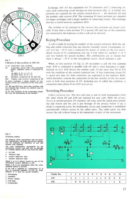
Exchange ASE 432 has equipment for 20 extensions and 2 connecting circuits,<br />
each connecting circuit having two time positions (fig. 3). A further two<br />
positions are required for the central control devices — the identifier ID and<br />
the number code receiver KM. The remaining 10 times positions are intended<br />
for larger exchanges with a larger number <strong>of</strong> connecting circuits. The exchange<br />
also has a central memory equipment REG.<br />
The switches to be actuated in the various time positions are tested cyclically.<br />
Every time a time position T8 is passed, ID and one <strong>of</strong> the extensions<br />
are connected to the highways so that a call can be detected.<br />
Fig. 3<br />
Utilization <strong>of</strong> time positions in ASE 432<br />
1—16 Consecutive time positions<br />
SN Connecting circuit with voice-controlled<br />
duplex amplifier which is connected to<br />
the<br />
• caller in Tx (x = 1—7)<br />
• called party in 1 \ + s<br />
ID Identifier—connected in T8 and T16<br />
KM Number code receiver—connected in T8<br />
In larger exchanges a larger number <strong>of</strong> connecting<br />
circuits are connected in free time positions.<br />
SN, ID and KM have fixed time positions and<br />
(he extension line switches are allotted some <strong>of</strong><br />
them. Cf. fig. 2.<br />
In the time positions <strong>of</strong> the connecting circuits<br />
ID scans the information in the memory.<br />
Keying Procedure<br />
A call is made by keying the number <strong>of</strong> the wanted extension. Both the calling<br />
and called extension lines are thereby normally seized. Loudspeaker circuit<br />
Lai has +30 V and is connected by means <strong>of</strong> diodes to the two microphone<br />
circuits in 12 <strong>com</strong>binations (see fig. 4 with table) for numbers 1—9, 0<br />
and two buttons for special facilities. The <strong>com</strong>binations are so chosen that<br />
there is always +30 V on the microphone circuit, which indicates a call.<br />
When, in time position T8 (fig. 2), ID encounters a call, the line scanning<br />
stops. KM is connected in parallel with ID and a voice frequency is superimposed<br />
on Lai. KM detects the number code. At the same time ID in TI6<br />
tests the condition <strong>of</strong> the wanted extension line. A free connecting circuit SN<br />
is seized and data for both extensions are registered in the memory REG.<br />
which thereafter controls the connection <strong>of</strong> the line switches <strong>of</strong> the two extensions<br />
in both time positions <strong>of</strong> SN. Including test <strong>of</strong> called line condition, a<br />
connection takes about 20 ms (0.02 s) to set up.<br />
Switching Procedure<br />
Called extension free. The first call tone is sent to both loudspeakers from<br />
ID, after which ID and KM are released for new calls. With the privacy<br />
button in normal position SN transmits call tones until the called party presses<br />
the talk button and the call is put through. If the privacy button is up, a<br />
diode is connected across the loudspeaker circuit and connection is established<br />
automatically without action by the called party. The called party can thus<br />
answer the call without being in the immediate vicinity <strong>of</strong> the instrument.<br />
Fig. 4<br />
Extension station<br />
The diagram shows microphone and pre-amplifier,<br />
loudspeaker, call lamp and privacy button,<br />
and the principle for initiation <strong>of</strong> call and<br />
number code marking.<br />
The code <strong>com</strong>binations transmitted via the<br />
microphone circuits La2 and I 1)2 on pressing<br />
<strong>of</strong> a number button will be seen from the table:<br />
— uo tone<br />
a full-wave tone<br />
b positive half-wave tone<br />
c negative half-wave tone<br />
Signal a or b is always issued on one <strong>of</strong> the<br />
microphone circuits. Indicates a call.<br />
Digits 1—9, 0 are transmitted when the corresponding<br />
button is pressed.<br />
If the call is initiated by <strong>com</strong>bination 12, it<br />
goes to extension numbers 11—19, 10. Combination<br />
11 is used for special facilities.<br />
© Microphone<br />
© Amplifier<br />
© Privacy burton<br />
© Call lamp<br />
© Loudspeaker<br />
Comb. No.<br />
La2<br />
Lb2<br />
1 2<br />
a a<br />
- b<br />
3<br />
-<br />
b<br />
4<br />
c<br />
b<br />
5<br />
c<br />
a<br />
6<br />
-<br />
a<br />
7<br />
a<br />
a<br />
8<br />
a<br />
c<br />
9<br />
b<br />
c<br />
0<br />
b<br />
-<br />
11<br />
b<br />
a<br />
12<br />
b<br />
b<br />
57


