A Dynamic Voltage Restorer based on Matrix Converter with Fuzzy ...
A Dynamic Voltage Restorer based on Matrix Converter with Fuzzy ...
A Dynamic Voltage Restorer based on Matrix Converter with Fuzzy ...

You also want an ePaper? Increase the reach of your titles
YUMPU automatically turns print PDFs into web optimized ePapers that Google loves.
POWER ENGINEERING AND ELECTRICAL ENGINEERING<br />
VOLUME: 10 | NUMBER: 3 | 2012 | SEPTEMBER<br />
voltages. The advantage of ISVM over DSVM is the<br />
simplicity of implementati<strong>on</strong>. One disadvantage of PI<br />
c<strong>on</strong>troller is using fixed gains which may cause the<br />
c<strong>on</strong>troller not to provide the suitable performance<br />
specially when there are variati<strong>on</strong>s in system parameters<br />
or operating c<strong>on</strong>diti<strong>on</strong>s. To overcome this problem, a PI<br />
c<strong>on</strong>troller utilizing fuzzy logic algorithm is used instead<br />
of the simple PI c<strong>on</strong>troller. The fuzzy algorithm can<br />
adjust the value of the two gains in the PI c<strong>on</strong>troller in<br />
order to make a better resp<strong>on</strong>se to the system operating<br />
point variati<strong>on</strong>s.<br />
In this paper, the proposed DVR structure is<br />
introduced in Secti<strong>on</strong> 2. Indirect space vector modulati<strong>on</strong><br />
for matrix c<strong>on</strong>verters is reviewed in Secti<strong>on</strong> 3, followed<br />
by fuzzy c<strong>on</strong>trol strategy of DVR in Secti<strong>on</strong> 4. Typical<br />
system simulati<strong>on</strong>s and numerical results via<br />
MATLAB/Simulink software are presented in Secti<strong>on</strong> 5.<br />
In Secti<strong>on</strong> 6, the c<strong>on</strong>venti<strong>on</strong>al PI c<strong>on</strong>troller is compared<br />
<strong>with</strong> the proposed fuzzy PI c<strong>on</strong>troller. Finally, Secti<strong>on</strong> 7<br />
c<strong>on</strong>cludes the discussi<strong>on</strong>.<br />
2. DVR Topology<br />
The main functi<strong>on</strong> of a DVR is voltage injecti<strong>on</strong> to<br />
compensate the voltage drop due to the voltage sag<br />
occurrence. In the other word DVR restores the load<br />
voltage to its rated value. To do this, DVR needs to<br />
exchange active and reactive power <strong>with</strong> the system.<br />
There are two types of DVR in general: 1) DVR <strong>with</strong> no<br />
energy storage system, 2) DVR <strong>with</strong> energy storage<br />
system. Each type has two topologies: 1) supply-sidec<strong>on</strong>nected<br />
c<strong>on</strong>verter, and 2) load-side-c<strong>on</strong>nected<br />
c<strong>on</strong>verter. All of the menti<strong>on</strong>ed topologies are compared<br />
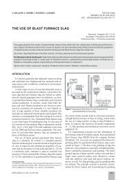
in [4] and the no energy storage DVR topology <strong>with</strong> loadside-c<strong>on</strong>nected<br />
c<strong>on</strong>verter has been evaluated as the best<br />
<strong>on</strong>e which is shown in Fig. 1.<br />
which means a DVR <strong>with</strong> no energy storage and loadside<br />
c<strong>on</strong>nected c<strong>on</strong>verter. According to Fig. 1 two<br />
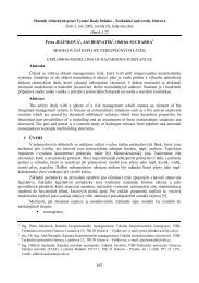
c<strong>on</strong>verters are replaced by a matrix c<strong>on</strong>verter and the DClink<br />
capacitor is removed. Figure 2 shows the resultant<br />
DVR system.<br />
Fig. 2: <strong>Matrix</strong> c<strong>on</strong>verter <str<strong>on</strong>g>based</str<strong>on</strong>g> DVR.<br />
The input voltage of matrix c<strong>on</strong>verter comes from<br />
the load and the output of matrix c<strong>on</strong>verter is c<strong>on</strong>nected<br />
to an injecti<strong>on</strong> transformer. <strong>Matrix</strong> c<strong>on</strong>verter c<strong>on</strong>trols the<br />
required compensati<strong>on</strong> voltage and injects that voltage<br />
through the transformer. To reduce harm<strong>on</strong>ics, both input<br />
and output of matrix c<strong>on</strong>verter are supplied <strong>with</strong> filters.<br />
There is no energy storage device and the energy is taken<br />
from the grid.<br />
3. Indirect Space Vector Modulati<strong>on</strong><br />
for <strong>Matrix</strong> C<strong>on</strong>verters<br />
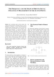
<strong>Matrix</strong> C<strong>on</strong>verter is made up of nine bi-directi<strong>on</strong>al<br />
switches arranged in an array of in such a way as to<br />
enable any input phase to be c<strong>on</strong>nected to any output<br />
phase at any time (Fig. 3). The switch duty cycles are<br />
modulated to produce desired output voltage from the<br />
supply voltage. There are various modulati<strong>on</strong> techniques<br />
such as Venturini modulati<strong>on</strong>, Optimum Venturini<br />
modulati<strong>on</strong>, and Space Vector modulati<strong>on</strong>s (SVM). The<br />
last <strong>on</strong>e has two types: direct SVM, and indirect SVM<br />
which is utilized in this paper.<br />
Fig. 1: General Type of DVR <strong>with</strong> no energy storage and load-sidec<strong>on</strong>nected<br />
c<strong>on</strong>verter.<br />
As there is no energy storage device in this<br />
topology, DVR needs a minimum system voltage to work<br />
properly and it may not be able to compensate very deep<br />
sags but the lack of energy storage device is a great<br />
ec<strong>on</strong>omical advantage. Furthermore, most usual sags are<br />
<strong>with</strong>in the range of DVR limits. The matrix c<strong>on</strong>verter<br />
<str<strong>on</strong>g>based</str<strong>on</strong>g> DVR in this paper is established <strong>on</strong> this topology<br />
Fig. 3: <strong>Matrix</strong> c<strong>on</strong>verter topology.<br />
In indirect method, matrix c<strong>on</strong>verter is modeled as<br />
two stage back-to-back c<strong>on</strong>verter: a rectificati<strong>on</strong> stage to<br />
create an imaginary DC link voltage, and an inverter<br />
© 2012 ADVANCES IN ELECTRICAL AND ELECTRONIC ENGINEERING 144