A Dynamic Voltage Restorer based on Matrix Converter with Fuzzy ...
A Dynamic Voltage Restorer based on Matrix Converter with Fuzzy ...
A Dynamic Voltage Restorer based on Matrix Converter with Fuzzy ...

Create successful ePaper yourself
Turn your PDF publications into a flip-book with our unique Google optimized e-Paper software.
POWER ENGINEERING AND ELECTRICAL ENGINEERING<br />
VOLUME: 10 | NUMBER: 3 | 2012 | SEPTEMBER<br />
The load voltage is compared <strong>with</strong> the reference<br />
voltage and produces an error which is the fuzzy<br />
c<strong>on</strong>troller input. This fuzzy PI c<strong>on</strong>troller is shown in<br />
Fig. 10b) and finally the calculated compensati<strong>on</strong> voltage<br />
by fuzzy logic system is added to the feedforward<br />
voltage. The resultant voltage is inserted to the matrix<br />
c<strong>on</strong>verter c<strong>on</strong>troller to produce the signals for its IGBTs.<br />
As it is menti<strong>on</strong>ed before, the output value of fuzzy logic<br />
systems are between 0 and 1. Therefore it needs to be<br />
multiplied before applying to PI c<strong>on</strong>troller and in<br />
Fig. 10b), K i ,i={1,2,3,4} are scaling factors which are<br />
defined through trial-and-error by repetitive simulati<strong>on</strong>s<br />
to achieve the best resp<strong>on</strong>se from the c<strong>on</strong>troller.<br />
5. Simulati<strong>on</strong>s<br />
The proposed matrix c<strong>on</strong>verter <str<strong>on</strong>g>based</str<strong>on</strong>g> DVR is simulated<br />
using MATLAB/Simulink software <strong>with</strong> discrete soluti<strong>on</strong><br />
and the time step is set to 2 µsec. The simulated system<br />
parameters are given in Tab. 3. A Discrete 3-phase PLL<br />
block <strong>with</strong> K p =180, K i =3200 and K d =1 is used to create<br />
a reference signal that is menti<strong>on</strong> in secti<strong>on</strong> 4. There are<br />
18 IGBT/Diode blocks <strong>with</strong> R <strong>on</strong> =1 mΩ and R s =100 kΩ<br />
to simulate a three phase matrix c<strong>on</strong>verter. The fuzzy<br />
logic c<strong>on</strong>troller is simulated using <strong>Fuzzy</strong> Logic<br />
C<strong>on</strong>troller block in <strong>Fuzzy</strong> Logic Toolbox of<br />
MATLAB/Simulink and the appropriate membership<br />
functi<strong>on</strong>s are inserted to these blocks according to Fig. 9.<br />
In this paper, the behaviors of proposed DVR under<br />
balanced sag/swell as well as unbalanced disturbances<br />
and harm<strong>on</strong>ic polluti<strong>on</strong> have been studied.<br />
Tab.3: Test case system parameters.<br />
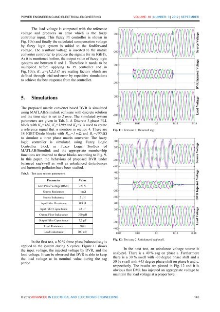
Fig. 11: Test case 1: Balanced sag.<br />
Parameter<br />
Value<br />
Grid Phase <str<strong>on</strong>g>Voltage</str<strong>on</strong>g> (RMS) 220 V<br />
Source Resistance<br />
1 mΩ<br />
Source Inductance 2 µH<br />
Input Filter Resistance 0,8 Ω<br />
Input Filter Capacitance 43 µF<br />
Output Filter Inductance 300 µH<br />
Output Filter Capacitance 7,2 µF<br />
Load Resistance<br />
50 Ω<br />
Load Inductance 200 mH<br />
In the first test, a 30 % three-phase balanced sag is<br />
applied to the system during 5 cycles. Figure 11 shows<br />
the input voltage, the injected voltage by DVR, and the<br />
load voltage. It can be observed that DVR is able to keep<br />
the load voltage at its nominal value during the sag<br />
period.<br />
Fig. 12: Test case 2: Unbalanced sag/swell.<br />
In the next test, an unbalance voltage source is<br />
analyzed. There is a 40 % sag <strong>on</strong> phase a. Furthermore<br />
there is a 30 % swell <strong>with</strong> -30 degree phase shift and a<br />
50 % swell <strong>with</strong> +45 degree phase shift <strong>on</strong> phase b and c,<br />
respectively. The results are plotted in Fig. 12 and it is<br />
obvious that DVR has injected an appropriate voltage to<br />
maintain the load voltage at a proper level.<br />
© 2012 ADVANCES IN ELECTRICAL AND ELECTRONIC ENGINEERING 148