Whilst every care has been taken in the preparation - MacAssemble
Whilst every care has been taken in the preparation - MacAssemble
Whilst every care has been taken in the preparation - MacAssemble

Create successful ePaper yourself
Turn your PDF publications into a flip-book with our unique Google optimized e-Paper software.
<strong>Whilst</strong> <strong>every</strong> <strong>care</strong> <strong>has</strong> <strong>been</strong> <strong>taken</strong> <strong>in</strong> <strong>the</strong> <strong>preparation</strong> of <strong>the</strong> <strong>in</strong>formation conta<strong>in</strong>ed <strong>in</strong> this manual,<br />
details and specifications are subject to change without notice. Nei<strong>the</strong>r <strong>the</strong> Manufacturer nor<br />
<strong>the</strong> Dealer supply<strong>in</strong>g this manual will be liable for <strong>the</strong> consequences result<strong>in</strong>g from any<br />
<strong>in</strong>accuracy of <strong>the</strong> <strong>in</strong>formation conta<strong>in</strong>ed <strong>in</strong> this manual under any circumstances.<br />
No part of this document may be reproduced, transmitted or published <strong>in</strong> any form or by any<br />
means without <strong>the</strong> prior permission of Omitec Information Services Ltd.<br />
TestBook and DeskJet are registered trademarks of Hewlett Packard Corporation. Dell and Latitude are<br />
registered trademarks of Dell Computer Corporation. SpeedStep and Pentium are registered trademarks of<br />
Intel Corporation. Microsoft and W<strong>in</strong>dows are registered trademarks of Microsoft Corporation. O<strong>the</strong>r trademarks and<br />
trade names may be used <strong>in</strong> this document, Omitec Information Services Ltd. disclaims any proprietary <strong>in</strong>terest <strong>in</strong><br />
trademarks and trade names o<strong>the</strong>r than its own.<br />
Publication Part No: DTC 4005A<br />
Published by Omitec Information Services Ltd. on behalf of Land Rover<br />
© Omitec Information Services Ltd.<br />
1st. edition copy - April 2001<br />
ii
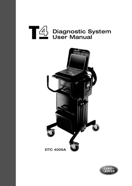
Preface<br />
This manual is designed to assist you with <strong>the</strong> correct assembly, operation and ma<strong>in</strong>tenance<br />
of your T4 diagnostic system. Note that <strong>the</strong> diagnostic system utilises <strong>in</strong>teractive technology,<br />
so that much of <strong>the</strong> <strong>in</strong>formation you need to operate <strong>the</strong> T4 successfully will be conta<strong>in</strong>ed ei<strong>the</strong>r<br />
<strong>in</strong> <strong>the</strong> system software or on <strong>the</strong> CD-ROMs accompany<strong>in</strong>g <strong>the</strong> T4 system. It is recommended<br />
that you use this manual <strong>in</strong> conjunction with your T4 equipment.<br />
Warn<strong>in</strong>gs, Cautions and Notes<br />
NOTE: Is used to emp<strong>has</strong>ise important and helpful <strong>in</strong>formation.<br />
CAUTION: Is used to emp<strong>has</strong>ise important <strong>in</strong>formation and procedures<br />
which must be followed to avoid damage to system components.<br />
WARNING: Is used to <strong>in</strong>dicate potentially hazardous situations and<br />
procedures which must be followed precisely to avoid serious <strong>in</strong>jury.<br />
iii
Glossary of Abbreviations and Symbols<br />
The follow<strong>in</strong>g abbreviations are used throughout this manual:<br />
Abbreviation Term or Description Abbreviation Term or Description<br />
AC Alternat<strong>in</strong>g Current LCD Liquid Crystal Display<br />
CD Compact Disc LED Light Emitt<strong>in</strong>g Diode<br />
CD-ROM<br />
Compact Disc Read Only<br />
Memory<br />
LH<br />
Left Hand<br />
°C degrees Centigrade MB MegaBytes<br />
cm/s centimetres per second mm millimetres<br />
© Copyright ms milliseconds<br />
DC Direct Current OBD On-Board Diagnostics<br />
DIN<br />
DeutscheIndustrie Normen<br />
(German Industrial Standards)<br />
Ω<br />
Ohms<br />
ECU Electronic Control Unit % Percentage<br />
EOBD<br />
European On-Board<br />
Diagnostics<br />
PC<br />
Personal Computer<br />
EU3<br />
European Union 3 (relates<br />
European exhaust-emissions<br />
legislation; also known as<br />
EOBD-3)<br />
RAM<br />
Random Access Memory<br />
FPGA<br />
Field Programmable Gate<br />
Array<br />
RH<br />
Right Hand<br />
GB GigaBytes SAE Society of Automotive<br />
Eng<strong>in</strong>eers<br />
Hz Hertz TestBook-1 TestBook-1 Diagnostic<br />
System<br />
ID Identification T4 T4 Diagnostic System<br />
IEC<br />
International Electrotechnical<br />
Commission (electrical<br />
standards organisation)<br />
TFT<br />
Th<strong>in</strong>-film transistor<br />
“ <strong>in</strong>ches Trademark<br />
ISO<br />
International Standards<br />
Organization<br />
TIM<br />
TestBook Interface Module<br />
k Thousand V Volts<br />
kg kilogrammes VIN Vehicle Identification Number<br />
J1962<br />
SAE standard for vehicle<br />
connector and diagnostic test<br />
equipment connectors<br />
VCSI<br />
Vehicle Communication Serial<br />
Interface<br />
LAN Local Area Network VOM Volt Ohm Module<br />
lbs<br />
pounds (weight)<br />
iv
CONTENTS<br />
Page<br />
Preface . . . . . . . . . . . . . . . . . . . . . . . . . . . . . . . . . . . . . . . . . . . . . . . . . . . . . . . . . . . . . . . . . .iii<br />
Warn<strong>in</strong>gs, Cautions and Notes. . . . . . . . . . . . . . . . . . . . . . . . . . . . . . . . . . . . . . . . . . . . . . . . iii<br />
Glossary of Abbreviations and Symbols . . . . . . . . . . . . . . . . . . . . . . . . . . . . . . . . . . . . . . . . .iv<br />
INTRODUCTION<br />
INTRODUCTION . . . . . . . . . . . . . . . . . . . . . . . . . . . . . . . . . . . . . . . . . . . . . . . . . . . . . . . . . . . 1<br />
HARDWARE & INSTALLATION<br />
T4 INSTALLATION GUIDE . . . . . . . . . . . . . . . . . . . . . . . . . . . . . . . . . . . . . . . . . . . . . . . . . . . 3<br />
Unpack<strong>in</strong>g Your T4 Equipment . . . . . . . . . . . . . . . . . . . . . . . . . . . . . . . . . . . . . . . . . . . . . 3<br />
Full T4 Package . . . . . . . . . . . . . . . . . . . . . . . . . . . . . . . . . . . . . . . . . . . . . . . . . . . . . . . . . 3<br />
TestBook-1 to T4 upgrade package . . . . . . . . . . . . . . . . . . . . . . . . . . . . . . . . . . . . . . . . 3<br />
T4 Full Kit:<br />
T4 exploded view (<strong>in</strong>clud<strong>in</strong>g trolley) . . . . . . . . . . . . . . . . . . . . . . . . . . . . . . . . . . . . . . . . . . 4<br />
T4 Trolley base assembly . . . . . . . . . . . . . . . . . . . . . . . . . . . . . . . . . . . . . . . . . . . . . . . . . . 6<br />
T4 Trolley cab<strong>in</strong>et assembly . . . . . . . . . . . . . . . . . . . . . . . . . . . . . . . . . . . . . . . . . . . . . . . . 6<br />
Rear Cable Management Bar Attachment . . . . . . . . . . . . . . . . . . . . . . . . . . . . . . . . . . . . . 7<br />
Front Cab<strong>in</strong>et Handle Attachments . . . . . . . . . . . . . . . . . . . . . . . . . . . . . . . . . . . . . . . . . . 8<br />
T4 Hand Held Tester Diagnostic Port Attachment . . . . . . . . . . . . . . . . . . . . . . . . . . . . . . . 8<br />
Power Supply Distribution Unit . . . . . . . . . . . . . . . . . . . . . . . . . . . . . . . . . . . . . . . . . . . . . . 9<br />
TIM Unit (where supplied) . . . . . . . . . . . . . . . . . . . . . . . . . . . . . . . . . . . . . . . . . . . . . . . . . 9<br />
LAN Hub (where supplied) . . . . . . . . . . . . . . . . . . . . . . . . . . . . . . . . . . . . . . . . . . . . . . . . . 9<br />
Trolley Cab<strong>in</strong>et Top Pl<strong>in</strong>th Assembly . . . . . . . . . . . . . . . . . . . . . . . . . . . . . . . . . . . . . . . . 10<br />
Cable Storage Bracket Attachment . . . . . . . . . . . . . . . . . . . . . . . . . . . . . . . . . . . . . . . . . 10<br />
Laptop PC Case / Laptop PC Attachment . . . . . . . . . . . . . . . . . . . . . . . . . . . . . . . . . . . . 11<br />
Pr<strong>in</strong>ter Installation . . . . . . . . . . . . . . . . . . . . . . . . . . . . . . . . . . . . . . . . . . . . . . . . . . . . . . . 11<br />
Pr<strong>in</strong>ter Paper Collection Tray Attachment . . . . . . . . . . . . . . . . . . . . . . . . . . . . . . . . . . . . 12<br />
Laptop PC to Laptop PC case Installation . . . . . . . . . . . . . . . . . . . . . . . . . . . . . . . . . . . . 13<br />
Laptop PC Cable Connections . . . . . . . . . . . . . . . . . . . . . . . . . . . . . . . . . . . . . . . . . . . . . 13<br />
TestBook-1 to T4 Upgrade Kit:<br />
TestBook-1 to T4 Upgrade Package . . . . . . . . . . . . . . . . . . . . . . . . . . . . . . . . . . . . . . . 15<br />
TestBook-1 to T4 Upgrade - exploded view (<strong>in</strong>clud<strong>in</strong>g trolley). . . . . . . . . . . . . . . . . . . 16<br />
TestBook-1 to T4 Upgrade Procedure . . . . . . . . . . . . . . . . . . . . . . . . . . . . . . . . . . . . . 18<br />
Tools required . . . . . . . . . . . . . . . . . . . . . . . . . . . . . . . . . . . . . . . . . . . . . . . . . . . . . . . . . . 18<br />
Mount<strong>in</strong>g Bracket Fix<strong>in</strong>g Accessories . . . . . . . . . . . . . . . . . . . . . . . . . . . . . . . . . . . . . . . . 18<br />
Diagnostic Port Fix<strong>in</strong>g Accessories . . . . . . . . . . . . . . . . . . . . . . . . . . . . . . . . . . . . . . . . . 18<br />
TestBook-1 Disassembly . . . . . . . . . . . . . . . . . . . . . . . . . . . . . . . . . . . . . . . . . . . . . . . 18<br />
Diagnostic Port Attachment . . . . . . . . . . . . . . . . . . . . . . . . . . . . . . . . . . . . . . . . . . . . . . . 20<br />
Pr<strong>in</strong>ter/T4 Power Supply Support Bracket Refit . . . . . . . . . . . . . . . . . . . . . . . . . . . . . . . . 21<br />
TestBook-1 to T4 Mount<strong>in</strong>g Bracket Attachment . . . . . . . . . . . . . . . . . . . . . . . . . . . . . 23<br />
T4 Laptop PC Case Mount<strong>in</strong>g . . . . . . . . . . . . . . . . . . . . . . . . . . . . . . . . . . . . . . . . . . . . . 24<br />
Laptop PC to Laptop PC case Installation . . . . . . . . . . . . . . . . . . . . . . . . . . . . . . . . . . . . 25<br />
Laptop PC Cable Connections . . . . . . . . . . . . . . . . . . . . . . . . . . . . . . . . . . . . . . . . . . . . . 25<br />
Kens<strong>in</strong>gton Lock (optional fitt<strong>in</strong>g) . . . . . . . . . . . . . . . . . . . . . . . . . . . . . . . . . . . . . . . . . . . 26<br />
T4 System Cables (DTC4004A) . . . . . . . . . . . . . . . . . . . . . . . . . . . . . . . . . . . . . . . . . . . . 28<br />
Trolley Wheels . . . . . . . . . . . . . . . . . . . . . . . . . . . . . . . . . . . . . . . . . . . . . . . . . . . . . . . . .32<br />
T4 VCSI Extension Lead (DTC4007B) . . . . . . . . . . . . . . . . . . . . . . . . . . . . . . . . . . . . . . . 32<br />
v
CONTENTS<br />
Page<br />
PREPARING A SITE FOR T4 . . . . . . . . . . . . . . . . . . . . . . . . . . . . . . . . . . . . . . . . . . . . . . . . 33<br />
T4 LABELS . . . . . . . . . . . . . . . . . . . . . . . . . . . . . . . . . . . . . . . . . . . . . . . . . . . . . . . . . . . . . . 34<br />
Laptop PC Case . . . . . . . . . . . . . . . . . . . . . . . . . . . . . . . . . . . . . . . . . . . . . . . . . . . . . . . . 34<br />
T4 Hand Held Tester Diagnostic Port . . . . . . . . . . . . . . . . . . . . . . . . . . . . . . . . . . . . . . . . 34<br />
T4 Hand Held Tester . . . . . . . . . . . . . . . . . . . . . . . . . . . . . . . . . . . . . . . . . . . . . . . . . . . . 34<br />
TestBook-1 to T4 upgrade trolley . . . . . . . . . . . . . . . . . . . . . . . . . . . . . . . . . . . . . . . . . 35<br />
Additional labels . . . . . . . . . . . . . . . . . . . . . . . . . . . . . . . . . . . . . . . . . . . . . . . . . . . . . . . .35<br />
PARTS CODE LIST . . . . . . . . . . . . . . . . . . . . . . . . . . . . . . . . . . . . . . . . . . . . . . . . . . . . . . . . 36<br />
T4 LAPTOP PC COMPONENTS . . . . . . . . . . . . . . . . . . . . . . . . . . . . . . . . . . . . . . . . . . . . . 37<br />
Laptop PC (Front View) - General . . . . . . . . . . . . . . . . . . . . . . . . . . . . . . . . . . . . . . . . . . 37<br />
Laptop PC (Right Hand Side) . . . . . . . . . . . . . . . . . . . . . . . . . . . . . . . . . . . . . . . . . . . . . . 37<br />
Laptop PC (Left Hand Side) . . . . . . . . . . . . . . . . . . . . . . . . . . . . . . . . . . . . . . . . . . . . . . . 37<br />
Laptop PC (Rear View) . . . . . . . . . . . . . . . . . . . . . . . . . . . . . . . . . . . . . . . . . . . . . . . . . . . 38<br />
Laptop PC (Bottom View) . . . . . . . . . . . . . . . . . . . . . . . . . . . . . . . . . . . . . . . . . . . . . . . . . 38<br />
T4 HAND HELD TESTER COMPONENTS . . . . . . . . . . . . . . . . . . . . . . . . . . . . . . . . . . . . . 39<br />
General Care and Clean<strong>in</strong>g . . . . . . . . . . . . . . . . . . . . . . . . . . . . . . . . . . . . . . . . . . . . . . . 39<br />
Safety Precautions . . . . . . . . . . . . . . . . . . . . . . . . . . . . . . . . . . . . . . . . . . . . . . . . . . . . . . 39<br />
T4 HAND HELD TESTER OPERATION . . . . . . . . . . . . . . . . . . . . . . . . . . . . . . . . . . . . . . . . 40<br />
Display screen . . . . . . . . . . . . . . . . . . . . . . . . . . . . . . . . . . . . . . . . . . . . . . . . . . . . . . . . . 40<br />
Key pad . . . . . . . . . . . . . . . . . . . . . . . . . . . . . . . . . . . . . . . . . . . . . . . . . . . . . . . . . . . . . . 40<br />
25-way "D" Type Diagnostic Connector socket . . . . . . . . . . . . . . . . . . . . . . . . . . . . . . . . 41<br />
8-way M<strong>in</strong>i-DIN Connector socket . . . . . . . . . . . . . . . . . . . . . . . . . . . . . . . . . . . . . . . . . . 41<br />
Power socket . . . . . . . . . . . . . . . . . . . . . . . . . . . . . . . . . . . . . . . . . . . . . . . . . . . . . . . . . .41<br />
Network port . . . . . . . . . . . . . . . . . . . . . . . . . . . . . . . . . . . . . . . . . . . . . . . . . . . . . . . . . . . 41<br />
EOBD J1962 (16 p<strong>in</strong>) Connector Harness . . . . . . . . . . . . . . . . . . . . . . . . . . . . . . . . . . . . 41<br />
T4 Hand Held Tester Reprogramm<strong>in</strong>g . . . . . . . . . . . . . . . . . . . . . . . . . . . . . . . . . . . . . . . 41<br />
T4 SPECIFICATIONS . . . . . . . . . . . . . . . . . . . . . . . . . . . . . . . . . . . . . . . . . . . . . . . . . . . . . . 42<br />
Interface . . . . . . . . . . . . . . . . . . . . . . . . . . . . . . . . . . . . . . . . . . . . . . . . . . . . . . . . . . . . . . 42<br />
T4 Laptop PC Accessories . . . . . . . . . . . . . . . . . . . . . . . . . . . . . . . . . . . . . . . . . . . . . . . . 42<br />
Volts Ohm Measurement Capabilities . . . . . . . . . . . . . . . . . . . . . . . . . . . . . . . . . . . . . . . 43<br />
VOM Specification . . . . . . . . . . . . . . . . . . . . . . . . . . . . . . . . . . . . . . . . . . . . . . . . . . . . . . 43<br />
Vehicle Communication Serial Interface (VCSI) . . . . . . . . . . . . . . . . . . . . . . . . . . . . . . . 43<br />
Power Sources . . . . . . . . . . . . . . . . . . . . . . . . . . . . . . . . . . . . . . . . . . . . . . . . . . . . . . . . . 44<br />
Mechanical Design . . . . . . . . . . . . . . . . . . . . . . . . . . . . . . . . . . . . . . . . . . . . . . . . . . . . . . 44<br />
PHYSICAL SPECIFICATIONS . . . . . . . . . . . . . . . . . . . . . . . . . . . . . . . . . . . . . . . . . . . . . . . 45<br />
Dimensions and Weight . . . . . . . . . . . . . . . . . . . . . . . . . . . . . . . . . . . . . . . . . . . . . . . . . . 45<br />
Laptop PC Display. . . . . . . . . . . . . . . . . . . . . . . . . . . . . . . . . . . . . . . . . . . . . . . . . . . . . . . 45<br />
Laptop PC Battery . . . . . . . . . . . . . . . . . . . . . . . . . . . . . . . . . . . . . . . . . . . . . . . . . . . . . . . 45<br />
Laptop PC Power Supply Adapter. . . . . . . . . . . . . . . . . . . . . . . . . . . . . . . . . . . . . . . . . . . 45<br />
Connectors . . . . . . . . . . . . . . . . . . . . . . . . . . . . . . . . . . . . . . . . . . . . . . . . . . . . . . . . . . . . 45<br />
ENVIRONMENTAL SPECIFICATIONS . . . . . . . . . . . . . . . . . . . . . . . . . . . . . . . . . . . . . . . . 46<br />
vi
CONTENTS<br />
Page<br />
PROTECTING YOUR T4 . . . . . . . . . . . . . . . . . . . . . . . . . . . . . . . . . . . . . . . . . . . . . . . . . . . 47<br />
CLEANING T4 . . . . . . . . . . . . . . . . . . . . . . . . . . . . . . . . . . . . . . . . . . . . . . . . . . . . . . . . . . . . 47<br />
Clean<strong>in</strong>g <strong>the</strong> T4 laptop PC case . . . . . . . . . . . . . . . . . . . . . . . . . . . . . . . . . . . . . . . . . . . . 48<br />
Clean<strong>in</strong>g <strong>the</strong> T4 Laptop PC Display W<strong>in</strong>dow . . . . . . . . . . . . . . . . . . . . . . . . . . . . . . . . . . 48<br />
Clean<strong>in</strong>g <strong>the</strong> Touch Pad . . . . . . . . . . . . . . . . . . . . . . . . . . . . . . . . . . . . . . . . . . . . . . . . . . 48<br />
Clean<strong>in</strong>g <strong>the</strong> T4 Hand Held Tester . . . . . . . . . . . . . . . . . . . . . . . . . . . . . . . . . . . . . . . . . . 48<br />
Clean<strong>in</strong>g <strong>the</strong> T4 Hand Held Tester Diagnostic Port . . . . . . . . . . . . . . . . . . . . . . . . . . . . . 48<br />
POWERING T4 . . . . . . . . . . . . . . . . . . . . . . . . . . . . . . . . . . . . . . . . . . . . . . . . . . . . . . . . . . .49<br />
INTERNAL POWER (T4 Laptop PC) . . . . . . . . . . . . . . . . . . . . . . . . . . . . . . . . . . . . . . . . . . 50<br />
USING THE TOUCH PAD . . . . . . . . . . . . . . . . . . . . . . . . . . . . . . . . . . . . . . . . . . . . . . . . . . . 50<br />
COMPACT DISCS (CDs) . . . . . . . . . . . . . . . . . . . . . . . . . . . . . . . . . . . . . . . . . . . . . . . . . . . 51<br />
Us<strong>in</strong>g Compact Discs . . . . . . . . . . . . . . . . . . . . . . . . . . . . . . . . . . . . . . . . . . . . . . . . . . . . 51<br />
Play<strong>in</strong>g a Compact Disc . . . . . . . . . . . . . . . . . . . . . . . . . . . . . . . . . . . . . . . . . . . . . . . . . . 51<br />
CD Clean<strong>in</strong>g Procedure . . . . . . . . . . . . . . . . . . . . . . . . . . . . . . . . . . . . . . . . . . . . . . . . . . 52<br />
BEGINNING WORK WITH T4 . . . . . . . . . . . . . . . . . . . . . . . . . . . . . . . . . . . . . . . . . . . . . . . . 53<br />
Turn<strong>in</strong>g ON T4 . . . . . . . . . . . . . . . . . . . . . . . . . . . . . . . . . . . . . . . . . . . . . . . . . . . . . . . . .53<br />
Configuration . . . . . . . . . . . . . . . . . . . . . . . . . . . . . . . . . . . . . . . . . . . . . . . . . . . . . . . . . . 56<br />
SCREEN FORMAT . . . . . . . . . . . . . . . . . . . . . . . . . . . . . . . . . . . . . . . . . . . . . . . . . . . . . . . . 60<br />
HOW TO VIEW PICTURES . . . . . . . . . . . . . . . . . . . . . . . . . . . . . . . . . . . . . . . . . . . . . . . . . 60<br />
Picture Options . . . . . . . . . . . . . . . . . . . . . . . . . . . . . . . . . . . . . . . . . . . . . . . . . . . . . . . . .61<br />
Control Panel Options . . . . . . . . . . . . . . . . . . . . . . . . . . . . . . . . . . . . . . . . . . . . . . . . . . . 62<br />
RETURN DESTINATION MENU . . . . . . . . . . . . . . . . . . . . . . . . . . . . . . . . . . . . . . . . . . . . . . 63<br />
Welcome . . . . . . . . . . . . . . . . . . . . . . . . . . . . . . . . . . . . . . . . . . . . . . . . . . . . . . . . . . . . . . 63<br />
Model Selection . . . . . . . . . . . . . . . . . . . . . . . . . . . . . . . . . . . . . . . . . . . . . . . . . . . . . . . .63<br />
Manual Selection . . . . . . . . . . . . . . . . . . . . . . . . . . . . . . . . . . . . . . . . . . . . . . . . . . . . . . . 63<br />
Section Selection . . . . . . . . . . . . . . . . . . . . . . . . . . . . . . . . . . . . . . . . . . . . . . . . . . . . . . .63<br />
Category Selection . . . . . . . . . . . . . . . . . . . . . . . . . . . . . . . . . . . . . . . . . . . . . . . . . . . . . . 63<br />
Title Selection . . . . . . . . . . . . . . . . . . . . . . . . . . . . . . . . . . . . . . . . . . . . . . . . . . . . . . . . . . 63<br />
INTEGRITY TESTS . . . . . . . . . . . . . . . . . . . . . . . . . . . . . . . . . . . . . . . . . . . . . . . . . . . . . . . . 64<br />
How to Interpret <strong>the</strong> Results of <strong>the</strong> T4 Integrity Tests . . . . . . . . . . . . . . . . . . . . . . . . . . . . 65<br />
ROVING PROBE TEST . . . . . . . . . . . . . . . . . . . . . . . . . . . . . . . . . . . . . . . . . . . . . . . . . . . . 66<br />
How to Interpret <strong>the</strong> Results of <strong>the</strong> Rov<strong>in</strong>g Probe Test . . . . . . . . . . . . . . . . . . . . . . . . . . 67<br />
LAN CONNECTION TEST . . . . . . . . . . . . . . . . . . . . . . . . . . . . . . . . . . . . . . . . . . . . . . . . . . 68<br />
FILE SYSTEM . . . . . . . . . . . . . . . . . . . . . . . . . . . . . . . . . . . . . . . . . . . . . . . . . . . . . . . . . . . . 68<br />
vii
CONTENTS<br />
Page<br />
DIAGNOSTICS - GENERAL<br />
GETTING STARTED . . . . . . . . . . . . . . . . . . . . . . . . . . . . . . . . . . . . . . . . . . . . . . . . . . . . . . . 69<br />
DIAGNOSTIC CONTROL PANEL BUTTONS . . . . . . . . . . . . . . . . . . . . . . . . . . . . . . . . . . . 71<br />
Abort . . . . . . . . . . . . . . . . . . . . . . . . . . . . . . . . . . . . . . . . . . . . . . . . . . . . . . . . . . . . . . . . 71<br />
Back Track . . . . . . . . . . . . . . . . . . . . . . . . . . . . . . . . . . . . . . . . . . . . . . . . . . . . . . . . . . . . 71<br />
Pr<strong>in</strong>t . . . . . . . . . . . . . . . . . . . . . . . . . . . . . . . . . . . . . . . . . . . . . . . . . . . . . . . . . . . . . . . . . 71<br />
Help . . . . . . . . . . . . . . . . . . . . . . . . . . . . . . . . . . . . . . . . . . . . . . . . . . . . . . . . . . . . . . . . . . 71<br />
Cont<strong>in</strong>ue . . . . . . . . . . . . . . . . . . . . . . . . . . . . . . . . . . . . . . . . . . . . . . . . . . . . . . . . . . . . . . 71<br />
DIAGNOSTICS - LAND ROVER<br />
VIN PREFIX . . . . . . . . . . . . . . . . . . . . . . . . . . . . . . . . . . . . . . . . . . . . . . . . . . . . . . . . . . . . . 73<br />
CABLING GUIDE . . . . . . . . . . . . . . . . . . . . . . . . . . . . . . . . . . . . . . . . . . . . . . . . . . . . . . . . .74<br />
T4 CABLES . . . . . . . . . . . . . . . . . . . . . . . . . . . . . . . . . . . . . . . . . . . . . . . . . . . . . . . . . . . . . . 80<br />
T4 ERROR CODES . . . . . . . . . . . . . . . . . . . . . . . . . . . . . . . . . . . . . . . . . . . . . . . . . . . . . . . 97<br />
T4 RDS Error Codes . . . . . . . . . . . . . . . . . . . . . . . . . . . . . . . . . . . . . . . . . . . . . . . . . . . . 97<br />
Action Key . . . . . . . . . . . . . . . . . . . . . . . . . . . . . . . . . . . . . . . . . . . . . . . . . . . . . . . . . . . . 97<br />
HELPDESK<br />
DEALER CHECK LIST (BEFORE YOU RING) . . . . . . . . . . . . . . . . . . . . . . . . . . . . . . . . . . . 99<br />
Help Us to Help You . . . . . . . . . . . . . . . . . . . . . . . . . . . . . . . . . . . . . . . . . . . . . . . . . . . . . 99<br />
Vehicle Details and Reported Fault . . . . . . . . . . . . . . . . . . . . . . . . . . . . . . . . . . . . . . . . . 99<br />
Full details of Test type . . . . . . . . . . . . . . . . . . . . . . . . . . . . . . . . . . . . . . . . . . . . . . . . . . . 99<br />
Full details of any difficulties you’ve had us<strong>in</strong>g T4. . . . . . . . . . . . . . . . . . . . . . . . . . . . . . 99<br />
Cabl<strong>in</strong>g Draw<strong>in</strong>g Reference used . . . . . . . . . . . . . . . . . . . . . . . . . . . . . . . . . . . . . . . . . . . 99<br />
LOCAL TELEPHONE NUMBERS . . . . . . . . . . . . . . . . . . . . . . . . . . . . . . . . . . . . . . . . . . . . 101<br />
HELP DESK . . . . . . . . . . . . . . . . . . . . . . . . . . . . . . . . . . . . . . . . . . . . . . . . . . . . . . . . . . . . 102<br />
EXCHANGE TIMES . . . . . . . . . . . . . . . . . . . . . . . . . . . . . . . . . . . . . . . . . . . . . . . . . . . . . . 102<br />
T4 Laptop PC’s, Hand Held Testers, Diagnostic Ports, Pr<strong>in</strong>ters, TIM Units,<br />
Cables and Power supplies . . . . . . . . . . . . . . . . . . . . . . . . . . . . . . . . . . . . . . . . . . . . . . 102<br />
Compact Discs (CDs) . . . . . . . . . . . . . . . . . . . . . . . . . . . . . . . . . . . . . . . . . . . . . . . . . . . 102<br />
Returns . . . . . . . . . . . . . . . . . . . . . . . . . . . . . . . . . . . . . . . . . . . . . . . . . . . . . . . . . . . . . . 102<br />
DEALER RESPONSIBILITIES . . . . . . . . . . . . . . . . . . . . . . . . . . . . . . . . . . . . . . . . . . . . . . 103<br />
SERVICE LEVEL . . . . . . . . . . . . . . . . . . . . . . . . . . . . . . . . . . . . . . . . . . . . . . . . . . . . . . . . 103<br />
T4 and TIM units . . . . . . . . . . . . . . . . . . . . . . . . . . . . . . . . . . . . . . . . . . . . . . . . . . . . . . 103<br />
Exclusions . . . . . . . . . . . . . . . . . . . . . . . . . . . . . . . . . . . . . . . . . . . . . . . . . . . . . . . . . . . 103<br />
Compact Discs . . . . . . . . . . . . . . . . . . . . . . . . . . . . . . . . . . . . . . . . . . . . . . . . . . . . . . . . 103<br />
Pr<strong>in</strong>ter . . . . . . . . . . . . . . . . . . . . . . . . . . . . . . . . . . . . . . . . . . . . . . . . . . . . . . . . . . . . . . . 104<br />
Cables . . . . . . . . . . . . . . . . . . . . . . . . . . . . . . . . . . . . . . . . . . . . . . . . . . . . . . . . . . . . . . 104<br />
Trolley and Power Supplies . . . . . . . . . . . . . . . . . . . . . . . . . . . . . . . . . . . . . . . . . . . . . . 104<br />
T4 EXCHANGE MATRIX . . . . . . . . . . . . . . . . . . . . . . . . . . . . . . . . . . . . . . . . . . . . . . . . . . 105<br />
T4 CABLES . . . . . . . . . . . . . . . . . . . . . . . . . . . . . . . . . . . . . . . . . . . . . . . . . . . . . . . . . . . . . 106<br />
viii
INTRODUCTION<br />
INTRODUCTION<br />
This manual provides <strong>in</strong>formation for <strong>the</strong><br />
follow<strong>in</strong>g:<br />
• Assembly and operation <strong>in</strong>structions for a<br />
new T4 Diagnostic kit.<br />
• Upgrad<strong>in</strong>g <strong>the</strong> TestBook-1 system to <strong>the</strong><br />
new T4 standard.<br />
T4 is <strong>the</strong> latest model <strong>in</strong> a series of advanced<br />
vehicle diagnostic tools. The TestBook<br />
programme <strong>has</strong> successfully applied <strong>the</strong> most<br />
recent advances <strong>in</strong> Information Technology to<br />
provide easy to use diagnostic tools for <strong>the</strong> rapid<br />
analysis, servic<strong>in</strong>g and repair of a sophisticated<br />
range of modern day vehicles.<br />
Although <strong>every</strong> effort is made to produce<br />
accurate and up to date support literature, this<br />
User Manual should not be regarded as an<br />
<strong>in</strong>fallible guide to current specification, nor does<br />
it constitute an offer for <strong>the</strong> fitment of any<br />
particular system or component.<br />
T4 <strong>has</strong> <strong>been</strong> designed for ease of use with both<br />
diagnostic software and CD-ROM based “RAVE”<br />
technical <strong>in</strong>formation.<br />
The latest T4 provides compliance with <strong>the</strong> latest<br />
EU3 and OBD II emissions standards.<br />
T4 is a portable computer-based diagnostic tool<br />
designed to assist a service technician to<br />
perform <strong>the</strong> diagnostic analyses of electrical<br />
systems, eng<strong>in</strong>e management systems,<br />
transmission systems and a range of o<strong>the</strong>r<br />
electronic based control systems utilised <strong>in</strong><br />
automotive vehicles.<br />
The T4 software user <strong>in</strong>terface screen prompts<br />
<strong>the</strong> service technician to enter commands for<br />
select<strong>in</strong>g equipment self tests, retriev<strong>in</strong>g<br />
diagnostic <strong>in</strong>formation, runn<strong>in</strong>g vehicle<br />
diagnostics and chang<strong>in</strong>g vehicle configurations.<br />
TestBook <strong>has</strong> already made a major<br />
contribution to rais<strong>in</strong>g standards of customer<br />
satisfaction and improv<strong>in</strong>g <strong>the</strong> bus<strong>in</strong>ess success<br />
of dealerships and <strong>the</strong>ir staff. T4 utilises<br />
sophisticated software to provide an enhanced<br />
user-friendly solution to fur<strong>the</strong>r this reputation.<br />
As with any progressive activity, successive<br />
generations of TestBook have benefited from<br />
<strong>the</strong> feedback ga<strong>in</strong>ed from <strong>the</strong> real-life<br />
experiences of end-users. In order for future<br />
diagnostic developments to be equally<br />
successful, we always welcome your comments<br />
and suggestions on how <strong>the</strong> equipment and<br />
support services can be improved.<br />
One of <strong>the</strong> primary features of <strong>the</strong> new<br />
T4 diagnostic system is <strong>the</strong> <strong>in</strong>clusion of <strong>the</strong> T4<br />
Hand Held Tester with Diagnostic Port. The<br />
Hand Held Tester provides a convenient, easy to<br />
use, portable solution for many diagnostic<br />
applications encountered <strong>in</strong> an automotive<br />
technician’s daily rout<strong>in</strong>e.<br />
The T4 Hand Held Tester is powered directly<br />
from a vehicle’s J1962 diagnostic connector, and<br />
operates as a stand alone unit to provide generic<br />
scan-tool functionality as well as fault code<br />
read<strong>in</strong>g / clear<strong>in</strong>g, live data and basic<br />
configuration functions for a wide range of<br />
systems.<br />
1
INTRODUCTION<br />
New and revised programs can be quickly and<br />
easily down loaded to <strong>the</strong> T4 Hand Held Tester.<br />
The new software code is electronically<br />
transferred from <strong>the</strong> T4 laptop PC via an e<strong>the</strong>rnet<br />
connection to <strong>the</strong> VCSI on <strong>the</strong> dedicated<br />
Diagnostic Port and <strong>in</strong>to <strong>the</strong> T4 Hand Held<br />
Tester via <strong>the</strong> pr<strong>in</strong>ted circuit board which<br />
<strong>in</strong>terfaces between <strong>the</strong> T4 Hand Held Tester and<br />
its Diagnostic Port.<br />
A new high quality trolley provides a convenient<br />
workstation for mount<strong>in</strong>g <strong>the</strong> ma<strong>in</strong> T4<br />
components and hous<strong>in</strong>g a pr<strong>in</strong>ter and <strong>the</strong> VOM/<br />
VCSI electronics. The laptop PC is housed <strong>in</strong> a<br />
robust lockable cas<strong>in</strong>g for security and protection<br />
when not <strong>in</strong> use. The trolley also conta<strong>in</strong>s<br />
storage for CD-ROMs and <strong>in</strong>terface cables.<br />
An upgrade kit is also available which uses <strong>the</strong><br />
previous TestBook-1 trolley and pr<strong>in</strong>ter.<br />
This manual conta<strong>in</strong>s <strong>in</strong>structions for assembl<strong>in</strong>g<br />
a T4 trolley and also for convert<strong>in</strong>g a<br />
TestBook-1 trolley for T4 use.<br />
2
HARDWARE & INSTALLATION<br />
T4 INSTALLATION GUIDE<br />
Unpack<strong>in</strong>g Your T4 Equipment<br />
Before unpack<strong>in</strong>g and us<strong>in</strong>g your T4, remember<br />
that it is a sophisticated item of electronic<br />
equipment. Although T4 <strong>has</strong> <strong>been</strong> designed to<br />
be robust for general workshop use, it still needs<br />
to be handled with greater <strong>care</strong> than most o<strong>the</strong>r<br />
items of workshop equipment.<br />
Carefully remove <strong>the</strong> equipment from its<br />
packag<strong>in</strong>g and lay it out on a clean dry area such<br />
as an empty workbench or table. Check off <strong>the</strong><br />
<strong>in</strong>dividual items supplied with each T4 kit (refer<br />
to <strong>the</strong> parts code checklist at <strong>the</strong> end of this<br />
section and <strong>the</strong> packag<strong>in</strong>g labels supplied with<br />
your kit). See “Parts Code List” on page 36.<br />
TestBook-1 to T4 upgrade package<br />
Instructions for upgrad<strong>in</strong>g a TestBook-1 trolley<br />
for T4 use is provided later <strong>in</strong> this document. The<br />
upgrade kit <strong>in</strong>cludes <strong>the</strong> T4 laptop PC, T4 Hand<br />
Held Tester and Diagnostic Port and a kit of parts<br />
for convert<strong>in</strong>g <strong>the</strong> exist<strong>in</strong>g TestBook-1 trolley<br />
for T4 use.<br />
A full exploded view of an upgraded T4 system<br />
<strong>in</strong>clud<strong>in</strong>g TestBook-1 trolley is supplied later <strong>in</strong><br />
this section with components annotated to<br />
demonstrate a typical T4 upgrade set up and<br />
assist with <strong>the</strong> assembly operation.<br />
See “TestBook-1 to T4 Upgrade - exploded<br />
view (<strong>in</strong>clud<strong>in</strong>g trolley)” on page 16.<br />
If any items are miss<strong>in</strong>g, please contact your<br />
Help Desk. See “LOCAL TELEPHONE<br />
NUMBERS” on page 107.<br />
NOTE: Contents <strong>in</strong>spection should<br />
only be performed us<strong>in</strong>g <strong>the</strong> packag<strong>in</strong>g<br />
labels provided with your kit<br />
referenced aga<strong>in</strong>st <strong>the</strong> parts code checklist<br />
provided <strong>in</strong> this section of <strong>the</strong> user guide.<br />
Full T4 Package<br />
The full T4 package, <strong>in</strong>clud<strong>in</strong>g trolley is supplied<br />
<strong>in</strong> a kit form which can easily be assembled us<strong>in</strong>g<br />
<strong>the</strong> <strong>in</strong>structions provided <strong>in</strong> this manual.<br />
NOTE: Some items shown may be<br />
optional extras which are supplied at<br />
extra cost if required.<br />
A full exploded view of a T4 system <strong>in</strong>clud<strong>in</strong>g<br />
trolley is supplied on <strong>the</strong> follow<strong>in</strong>g pages with<br />
components annotated to demonstrate a typical<br />
T4 set up and assist with <strong>the</strong> assembly<br />
operation. See “T4 exploded view (<strong>in</strong>clud<strong>in</strong>g<br />
trolley)” on page 4.<br />
3
HARDWARE & INSTALLATION<br />
T4 exploded view (<strong>in</strong>clud<strong>in</strong>g trolley)<br />
16<br />
17<br />
9<br />
10 11<br />
14<br />
15<br />
18<br />
19<br />
20 21<br />
13<br />
12<br />
8<br />
22<br />
23<br />
24<br />
7<br />
25<br />
6<br />
5<br />
26<br />
27<br />
28<br />
4<br />
29<br />
3<br />
2<br />
1<br />
4
HARDWARE & INSTALLATION<br />
T4 parts key<br />
1. Lock<strong>in</strong>g wheels (2 off)<br />
2. H-frame base<br />
3. Trolley cab<strong>in</strong>et to H-frame base fix<strong>in</strong>g bolts<br />
(6 off)<br />
4. Pr<strong>in</strong>ter output paper tray<br />
5. Front RH handle<br />
6. Front handle fix<strong>in</strong>g bolt and lock<strong>in</strong>g washer<br />
(one per handle)<br />
7. Front LH handle<br />
8. DeskJet 350 Pr<strong>in</strong>ter<br />
9. Pr<strong>in</strong>ter fix<strong>in</strong>g brackets and w<strong>in</strong>g nuts (2 off)<br />
10. Spare pr<strong>in</strong>ter cartridge<br />
11. Pr<strong>in</strong>ter power supply adapter<br />
12. AC power supply distribution pack (5-way)<br />
13. LAN hub unit (e<strong>the</strong>rnet hub - optional<br />
accessory)<br />
14. Laptop PC case to pl<strong>in</strong>th camlatch keys<br />
15. Trolley pl<strong>in</strong>th and laptop PC case mount<strong>in</strong>g<br />
platform<br />
16. Laptop PC case lock keys<br />
17. Laptop PC case (conta<strong>in</strong><strong>in</strong>g Dell laptop<br />
PC)<br />
18. Pl<strong>in</strong>th countersunk mount<strong>in</strong>g screws (8 off)<br />
19. TIM power supply adapter and Velcro<br />
fix<strong>in</strong>g (optional accessory)<br />
20. TIM unit (optional accessory)<br />
21. Cable Management Bar<br />
22. Cable Management Bar fix<strong>in</strong>g bolts and<br />
lock<strong>in</strong>g washers (2 off - one per side)<br />
23. T4 Hand Held Tester Diagnostic Port<br />
mount<strong>in</strong>g screws and lock<strong>in</strong>g washers (4<br />
off - from <strong>in</strong>side cab<strong>in</strong>et)<br />
24. T4 Hand Held Tester Diagnostic Port<br />
(T4 Hand Held Tester not shown)<br />
25. Cable storage bracket<br />
(2 off, one each side of cab<strong>in</strong>et)<br />
26. Cable storage bracket fix<strong>in</strong>g screws<br />
(3 off per bracket)<br />
27. Pr<strong>in</strong>ter paper output tray mount<strong>in</strong>g screws<br />
(4 off)<br />
28. Trolley ma<strong>in</strong> column / cab<strong>in</strong>et<br />
29. Free-runn<strong>in</strong>g wheels (2 off)<br />
5
HARDWARE & INSTALLATION<br />
T4 Trolley base assembly<br />
T4 Trolley cab<strong>in</strong>et assembly<br />
a<br />
3<br />
2<br />
3<br />
2<br />
1. Remove <strong>the</strong> Ma<strong>in</strong> Column / Cab<strong>in</strong>et and<br />
accessories for <strong>the</strong> trolley from its<br />
packag<strong>in</strong>g, and ensure all <strong>the</strong> follow<strong>in</strong>g<br />
components are <strong>in</strong>cluded:<br />
Pack 1 of 3 (trolley base):<br />
• H-frame - 1 off<br />
• Lock<strong>in</strong>g wheels - 2 off<br />
• Free-runn<strong>in</strong>g wheels - 2 off<br />
2. Fit <strong>the</strong> two lock<strong>in</strong>g wheels to <strong>the</strong> front of <strong>the</strong><br />
H-frame by screw<strong>in</strong>g <strong>the</strong> wheel studs <strong>in</strong>to<br />
<strong>the</strong> threads provided on <strong>the</strong> underside of<br />
<strong>the</strong> H-frame.<br />
NOTE: The upper side of <strong>the</strong> rear left<br />
hand arm of <strong>the</strong> H-frame <strong>has</strong> two<br />
additional holes for fitment of an<br />
accessory (See “a” <strong>in</strong> illustration T4002<br />
above). Use this as a reference to ensure <strong>the</strong><br />
lock<strong>in</strong>g wheels are fitted <strong>in</strong> <strong>the</strong> correct<br />
position at <strong>the</strong> front of <strong>the</strong> H-frame base.<br />
3. Fit <strong>the</strong> two free-runn<strong>in</strong>g wheels to <strong>the</strong> rear<br />
of <strong>the</strong> H-frame base, by screw<strong>in</strong>g <strong>the</strong><br />
wheel bolts <strong>in</strong>to <strong>the</strong> threads provided at <strong>the</strong><br />
underside of <strong>the</strong> H-frame.<br />
1. Remove <strong>the</strong> cab<strong>in</strong>et and accessories from<br />
its packag<strong>in</strong>g, and ensure all <strong>the</strong> follow<strong>in</strong>g<br />
components are <strong>in</strong>cluded:<br />
Pack 2 of 3 & Pack 3 of 3:<br />
• Trolley Ma<strong>in</strong> Column / Cab<strong>in</strong>et - 1 off<br />
• Trolley fix<strong>in</strong>gs accessory bag - 1off<br />
(located <strong>in</strong> top drawer of cab<strong>in</strong>et)<br />
• Trolley 3-metre ACpower supply cable<br />
set - 1 off (located <strong>in</strong> top drawer of<br />
cab<strong>in</strong>et)<br />
• Front handles (with fitted grips) - 2 off<br />
• Rear Cable Management Bar (with fitted<br />
end caps) - 1off<br />
• Pr<strong>in</strong>ter paper collection tray - 1 off<br />
• Cable storage brackets - 2 off<br />
• Cab<strong>in</strong>et top pl<strong>in</strong>th - 1 off<br />
NOTE: The ma<strong>in</strong> column / cab<strong>in</strong>et<br />
comes complete with drawers, power<br />
distribution and pr<strong>in</strong>ter cables already<br />
fitted.<br />
2. Position <strong>the</strong> cab<strong>in</strong>et on top of <strong>the</strong> base,<br />
ensur<strong>in</strong>g <strong>the</strong> front of cab<strong>in</strong>et is fac<strong>in</strong>g <strong>the</strong><br />
two lock<strong>in</strong>g wheels.<br />
3. Fix <strong>the</strong> cab<strong>in</strong>et to base us<strong>in</strong>g <strong>the</strong> 6<br />
mount<strong>in</strong>g bolts (M8 x 20mm) and 6 lock<strong>in</strong>g<br />
washers (M8).<br />
6
HARDWARE & INSTALLATION<br />
Rear Cable Management Bar Attachment<br />
2<br />
3<br />
1. Remove <strong>the</strong> upper drawer from <strong>the</strong> trolley<br />
cab<strong>in</strong>et;<br />
• Open drawer<br />
• Raise latch on LH side drawer slider rail;<br />
lower latch on RH side drawer slider rail.<br />
• Remove drawer from cab<strong>in</strong>et.<br />
NOTE: In some cases drawer slider<br />
latches may operate <strong>in</strong> opposite<br />
orientation to that <strong>in</strong>dicated above.<br />
2. Lightly grease <strong>the</strong> ends of <strong>the</strong> Cable<br />
Management Bar with petroleum jelly and<br />
push <strong>in</strong>to apertures at <strong>the</strong> rear of <strong>the</strong><br />
cab<strong>in</strong>et.<br />
NOTE: Cable Management Bar ends<br />
may require some lateral force to<br />
ensure <strong>the</strong>y are aligned to <strong>the</strong><br />
mount<strong>in</strong>g apertures.<br />
3. Secure <strong>the</strong> ends of <strong>the</strong> Cable Management<br />
bar us<strong>in</strong>g 2 off M6 x 25mm socket head<br />
cap screws.<br />
7
HARDWARE & INSTALLATION<br />
Front Cab<strong>in</strong>et Handle Attachments<br />
T4 Hand Held Tester Diagnostic Port<br />
Attachment<br />
2<br />
3<br />
CAUTION: Each of <strong>the</strong> front cab<strong>in</strong>et<br />
handles are specific for <strong>the</strong> left or right<br />
hand sides; ensure you attach <strong>the</strong><br />
correct handle to <strong>the</strong> correspond<strong>in</strong>g side of<br />
<strong>the</strong> cab<strong>in</strong>et, o<strong>the</strong>rwise <strong>the</strong> cab<strong>in</strong>et upper<br />
drawer and top door will not open.<br />
1. Ensure <strong>the</strong> cab<strong>in</strong>et’s top door is <strong>in</strong> <strong>the</strong> fully<br />
closed position.<br />
CAUTION: If <strong>the</strong> cab<strong>in</strong>et’s top door is<br />
left <strong>in</strong> <strong>the</strong> open position, and <strong>the</strong> left<br />
handle is fitted <strong>in</strong> position, <strong>the</strong> door<br />
cannot <strong>the</strong>n be closed.<br />
2. Lightly grease <strong>the</strong> end of <strong>the</strong> left handle<br />
and <strong>in</strong>sert <strong>in</strong>to <strong>the</strong> aperture on <strong>the</strong> front left<br />
hand side of <strong>the</strong> trolley cab<strong>in</strong>et.<br />
3. Lock <strong>the</strong> LH handle <strong>in</strong> position us<strong>in</strong>g 1 off<br />
M6 x 25mm socket head cap screw.<br />
4. Lightly grease <strong>the</strong> end of <strong>the</strong> right handle<br />
and <strong>in</strong>sert <strong>in</strong>to <strong>the</strong> aperture on <strong>the</strong> front<br />
right hand side of <strong>the</strong> trolley cab<strong>in</strong>et.<br />
5. Lock <strong>the</strong> RH handle <strong>in</strong> position us<strong>in</strong>g 1 off<br />
M6 x 25mm socket head cap screw.<br />
4<br />
1<br />
1. Remove <strong>the</strong> T4 Hand Held Tester<br />
components from <strong>the</strong>ir packag<strong>in</strong>g and<br />
check <strong>the</strong> contents aga<strong>in</strong>st <strong>the</strong> packag<strong>in</strong>g<br />
label. Items should <strong>in</strong>clude:<br />
• T4 Hand Held Tester Diagnostic Port<br />
(DTC 4002A) - 1 off<br />
• T4 Hand Held Tester Diagnostic Port<br />
fix<strong>in</strong>gs - 4 screws and lock<strong>in</strong>g washers.<br />
3<br />
2. Align <strong>the</strong> Diagnostic Port to <strong>the</strong> mount<strong>in</strong>g<br />
holes on <strong>the</strong> right side of <strong>the</strong> upper trolley<br />
cab<strong>in</strong>et.<br />
3. Fix <strong>the</strong> Diagnostic Port to <strong>the</strong> trolley<br />
cab<strong>in</strong>et with 4 off M5 x 6mm screws and<br />
lock<strong>in</strong>g washers. Screws pass through<br />
from <strong>in</strong>side of cab<strong>in</strong>et at upper drawer and<br />
top door levels.<br />
NOTE: Lock<strong>in</strong>g washers are fitted<br />
directly under screw heads.<br />
2<br />
8
HARDWARE & INSTALLATION<br />
Power Supply Distribution Unit<br />
The 5 way power supply distribution unit is<br />
already <strong>in</strong>stalled <strong>in</strong> <strong>the</strong> trolley cab<strong>in</strong>et and will<br />
provide connection for AC power supply cables<br />
which will be routed through <strong>the</strong> cab<strong>in</strong>et to<br />
provide power supplies to <strong>the</strong> follow<strong>in</strong>g<br />
components:<br />
• Lap top computer<br />
• Pr<strong>in</strong>ter<br />
• T4 Hand Held Tester Diagnostic Port<br />
• TIM Unit (where fitted)<br />
• LAN hub (where fitted)<br />
The power distribution unit is attached to <strong>the</strong><br />
<strong>in</strong>side of <strong>the</strong> upper trolley cab<strong>in</strong>et at <strong>the</strong> left hand<br />
side and is secured to <strong>the</strong> cab<strong>in</strong>et by 2 off<br />
M4 x 6mm Posidriv screws and lock<strong>in</strong>g washers.<br />
NOTE: The pr<strong>in</strong>ter power supply cable<br />
is already connected to <strong>the</strong> AC power<br />
supply distribution outlet and routed<br />
through <strong>the</strong> trolley cab<strong>in</strong>et.<br />
TIM Unit (where supplied)<br />
The TIM unit is an optional accessory, which is<br />
located <strong>in</strong>side <strong>the</strong> top right hand side of <strong>the</strong><br />
trolley cab<strong>in</strong>et. The TIM unit is secured to <strong>the</strong><br />
upper cab<strong>in</strong>et shelf with two screws, so that <strong>the</strong><br />
TIM unit connector and sockets can be accessed<br />
through an aperture at <strong>the</strong> back of <strong>the</strong> trolley<br />
cab<strong>in</strong>et.<br />
LAN Hub (where supplied)<br />
The LAN hub is an optional accessory, which is<br />
located <strong>in</strong>side <strong>the</strong> top left hand side of <strong>the</strong> trolley<br />
cab<strong>in</strong>et. The LAN hub is secured to <strong>the</strong> upper<br />
cab<strong>in</strong>et shelf with two raised screws which locate<br />
<strong>in</strong>to slots <strong>in</strong> <strong>the</strong> bottom of <strong>the</strong> LAN hub case.<br />
Place 2 off M3 x 8mm screws <strong>in</strong>to <strong>the</strong> 2 holes on<br />
<strong>the</strong> upper cab<strong>in</strong>et shelf where <strong>the</strong> LAN hub will<br />
locate. Screw <strong>the</strong> heads of <strong>the</strong> M3 screws to<br />
with<strong>in</strong> 1.5 mm of <strong>the</strong> panel shelf to leave <strong>the</strong><br />
screw heads slightly raised.<br />
To locate <strong>the</strong> LAN hub unit, place <strong>the</strong> unit over<br />
<strong>the</strong> raised screw heads and <strong>the</strong>n slide <strong>the</strong> unit<br />
towards <strong>the</strong> left hand side of <strong>the</strong> trolley cab<strong>in</strong>et<br />
so that <strong>the</strong> LAN connection sockets can be<br />
accessed through <strong>the</strong> aperture at <strong>the</strong> back of <strong>the</strong><br />
trolley cab<strong>in</strong>et.<br />
The power supply for <strong>the</strong> LAN hub is 5V DC<br />
which is supplied from an AC to DC converter<br />
which is to be located on <strong>the</strong> trolley cab<strong>in</strong>et<br />
upper shelf us<strong>in</strong>g <strong>the</strong> Velcro strip supplied.<br />
An AC to 18V DC power supply converter for <strong>the</strong><br />
TIM unit is attached to <strong>the</strong> top of <strong>the</strong> TIM unit by<br />
a Velcro strip. The AC power supply lead to <strong>the</strong><br />
converter is connected to <strong>the</strong> 5-way AC power<br />
supply distribution unit and <strong>the</strong> DC connector<br />
from <strong>the</strong> converter connects to <strong>the</strong> TIM unit.<br />
9
HARDWARE & INSTALLATION<br />
Trolley Cab<strong>in</strong>et Top Pl<strong>in</strong>th Assembly<br />
1. Replace <strong>the</strong> upper trolley cab<strong>in</strong>et drawer,<br />
by align<strong>in</strong>g <strong>the</strong> slider rails on <strong>the</strong> drawer<br />
and cab<strong>in</strong>et and push<strong>in</strong>g <strong>the</strong> drawer <strong>in</strong> to<br />
its fully closed position.<br />
Cable Storage Bracket Attachment<br />
2. Ensure <strong>the</strong> trolley upper cab<strong>in</strong>et door is <strong>in</strong><br />
<strong>the</strong> closed position and latched shut.<br />
4<br />
3<br />
5<br />
3<br />
2<br />
3. Attach <strong>the</strong> Camlock to <strong>the</strong> pl<strong>in</strong>th by<br />
<strong>in</strong>sert<strong>in</strong>g <strong>the</strong> lock barrel and cam through<br />
<strong>the</strong> hole of <strong>the</strong> lock bracket on <strong>the</strong> front<br />
underside of <strong>the</strong> pl<strong>in</strong>th. Check <strong>the</strong><br />
orientation of <strong>the</strong> camlock and that <strong>the</strong> lock<br />
operates correctly (i.e when <strong>the</strong> lock keys<br />
are turned <strong>the</strong> lock<strong>in</strong>g bar rotates through<br />
<strong>the</strong> slot <strong>in</strong> <strong>the</strong> top of <strong>the</strong> pl<strong>in</strong>th). Fit and<br />
tighten <strong>the</strong> lock<strong>in</strong>g nut to <strong>the</strong> back of <strong>the</strong><br />
lock barrel.<br />
NOTE: The cam does not need to be<br />
removed from <strong>the</strong> lock barrel <strong>in</strong> order<br />
for it to pass through <strong>the</strong> hole <strong>in</strong> <strong>the</strong><br />
pl<strong>in</strong>th’s lock bracket or pass <strong>the</strong> lock<strong>in</strong>g nut<br />
over it.<br />
1. Pull out lower cab<strong>in</strong>et drawer for access to<br />
<strong>the</strong> <strong>in</strong>ner cab<strong>in</strong>et.<br />
2. Push one of <strong>the</strong> cable brackets through <strong>the</strong><br />
slot <strong>in</strong> <strong>the</strong> left side of <strong>the</strong> cab<strong>in</strong>et and align<br />
<strong>the</strong> bracket fix<strong>in</strong>g nuts with <strong>the</strong> holes <strong>in</strong> <strong>the</strong><br />
side of <strong>the</strong> cab<strong>in</strong>et.<br />
3. Secure <strong>the</strong> bracket <strong>in</strong> place us<strong>in</strong>g 3 off<br />
M4 x 6mm fix<strong>in</strong>g screws and lock<strong>in</strong>g<br />
washers.<br />
4. Repeat <strong>the</strong> above procedure to secure <strong>the</strong><br />
rema<strong>in</strong><strong>in</strong>g cable bracket to <strong>the</strong> right side of<br />
<strong>the</strong> trolley.<br />
5. Close <strong>the</strong> lower cab<strong>in</strong>et drawer.<br />
4. Align <strong>the</strong> pl<strong>in</strong>th to <strong>the</strong> top of <strong>the</strong> cab<strong>in</strong>et,<br />
ensur<strong>in</strong>g <strong>the</strong> lock is at <strong>the</strong> front face of <strong>the</strong><br />
cab<strong>in</strong>et and <strong>the</strong> PC case locat<strong>in</strong>g tags<br />
uppermost.<br />
5. Secure <strong>the</strong> pl<strong>in</strong>th to <strong>the</strong> trolley cab<strong>in</strong>et<br />
us<strong>in</strong>g <strong>the</strong> 8 off M4 x 6mm countersunk<br />
screws supplied with <strong>the</strong> kit.<br />
10
HARDWARE & INSTALLATION<br />
Laptop PC Case / Laptop PC Attachment<br />
2<br />
3<br />
Pr<strong>in</strong>ter Installation<br />
1. Unpack <strong>the</strong> pr<strong>in</strong>ter components and check<br />
<strong>the</strong>m aga<strong>in</strong>st <strong>the</strong> parts contents listed <strong>in</strong><br />
<strong>the</strong> pr<strong>in</strong>ter booklet.<br />
2. Ensure <strong>the</strong> pr<strong>in</strong>ter cartridge is correctly<br />
assembled to <strong>the</strong> pr<strong>in</strong>ter unit (refer to <strong>the</strong><br />
pr<strong>in</strong>ter booklet supplied with <strong>the</strong> pr<strong>in</strong>ter).<br />
3. Open <strong>the</strong> trolley cab<strong>in</strong>et lower drawer.<br />
5<br />
4<br />
The laptop PC case is normally supplied with <strong>the</strong><br />
laptop PC already fitted. If <strong>the</strong> laptop PC <strong>has</strong><br />
<strong>been</strong> supplied separately from <strong>the</strong> PC case, and/<br />
or <strong>the</strong> laptop PC <strong>has</strong> <strong>been</strong> removed from <strong>the</strong> PC<br />
case prior to full T4 <strong>in</strong>stallation, <strong>the</strong> laptop PC will<br />
have to be <strong>in</strong>stalled <strong>in</strong>to <strong>the</strong> laptop PC case as<br />
described later <strong>in</strong> this section - See “Laptop PC<br />
to Laptop PC case Installation” on page 13.<br />
1. Unpack <strong>the</strong> laptop PC case and laptop PC<br />
from its packag<strong>in</strong>g and check <strong>the</strong> contents<br />
aga<strong>in</strong>st <strong>the</strong> components listed on <strong>the</strong><br />
packag<strong>in</strong>g label.<br />
4. Place <strong>the</strong> pr<strong>in</strong>ter <strong>in</strong> <strong>the</strong> front of <strong>the</strong> drawer<br />
with <strong>the</strong> control panel face up.<br />
5. Secure <strong>the</strong> pr<strong>in</strong>ter <strong>in</strong> position aga<strong>in</strong>st <strong>the</strong><br />
front of <strong>the</strong> door by us<strong>in</strong>g <strong>the</strong> two brackets,<br />
w<strong>in</strong>g nuts and studs <strong>in</strong> <strong>the</strong> front of <strong>the</strong><br />
drawer. F<strong>in</strong>ger tighten <strong>the</strong> w<strong>in</strong>g nuts.<br />
2. Align <strong>the</strong> locat<strong>in</strong>g slots <strong>in</strong> <strong>the</strong> bottom of <strong>the</strong><br />
PC case with <strong>the</strong> lugs on <strong>the</strong> trolley pl<strong>in</strong>th.<br />
3. Slide <strong>the</strong> laptop PC case towards <strong>the</strong> rear<br />
of <strong>the</strong> trolley pl<strong>in</strong>th.<br />
NOTE: If <strong>the</strong> ends of <strong>the</strong> locat<strong>in</strong>g lugs<br />
are pressed down, it will not be easy to<br />
locate <strong>the</strong> laptop PC case correctly. In<br />
this <strong>in</strong>stance gently lever up <strong>the</strong> ends of <strong>the</strong><br />
locat<strong>in</strong>g lugs us<strong>in</strong>g a flat bladed screwdriver<br />
to facilitate easier location and attachment of<br />
<strong>the</strong> PC laptop case to <strong>the</strong> mount<strong>in</strong>g bracket;<br />
note <strong>the</strong> gap should be between<br />
7.5 mm & 8 mm.<br />
4. Lock <strong>the</strong> laptop PC case <strong>in</strong> position and<br />
remove <strong>the</strong> keys from <strong>the</strong> lock. Store <strong>the</strong><br />
keys <strong>in</strong> a secure location.<br />
NOTE: The keys can only be removed<br />
<strong>in</strong> <strong>the</strong> locked condition.<br />
6. Insert <strong>the</strong> pr<strong>in</strong>ter power supply <strong>in</strong>to <strong>the</strong><br />
right hand side of <strong>the</strong> drawer, beh<strong>in</strong>d <strong>the</strong><br />
pr<strong>in</strong>ter, and connect <strong>the</strong> AC power supply 2<br />
p<strong>in</strong> plug to <strong>the</strong> pr<strong>in</strong>ter power supply unit.<br />
NOTE: The AC power supply cable for<br />
<strong>the</strong> pr<strong>in</strong>ter’s AC to DC converter is<br />
already <strong>in</strong>stalled <strong>in</strong>side <strong>the</strong> trolley<br />
cab<strong>in</strong>et.<br />
6<br />
11
HARDWARE & INSTALLATION<br />
9<br />
Pr<strong>in</strong>ter Paper Collection Tray<br />
Attachment<br />
1. Unpack <strong>the</strong> pr<strong>in</strong>ter paper collection tray<br />
and fix<strong>in</strong>gs (4 off M5 x 10mm screws).<br />
2. Tighten <strong>the</strong> screws <strong>in</strong>to <strong>the</strong> holes on <strong>the</strong><br />
front of <strong>the</strong> trolley cab<strong>in</strong>et so that <strong>the</strong> screw<br />
heads are raised approximately 2mm from<br />
<strong>the</strong> front face of <strong>the</strong> trolley cab<strong>in</strong>et.<br />
See “T4 exploded view (<strong>in</strong>clud<strong>in</strong>g<br />
trolley)” on page 4.<br />
8<br />
7<br />
7. Connect <strong>the</strong> power supply unit DC lead to<br />
<strong>the</strong> pr<strong>in</strong>ter power <strong>in</strong>put socket.<br />
8. Connect <strong>the</strong> pr<strong>in</strong>ter parallel port cable to<br />
<strong>the</strong> pr<strong>in</strong>ter.<br />
NOTE: The pr<strong>in</strong>ter cable is already<br />
<strong>in</strong>stalled <strong>in</strong> <strong>the</strong> trolley cab<strong>in</strong>et. The<br />
pr<strong>in</strong>ter connector may be orientated<br />
with <strong>the</strong> cable fac<strong>in</strong>g upwards (as shown<br />
above), or downwards.<br />
3. Position <strong>the</strong> eyelets <strong>in</strong> <strong>the</strong> flange of <strong>the</strong><br />
paper over <strong>the</strong> screw heads and lower <strong>the</strong><br />
pr<strong>in</strong>ter paper collection tray <strong>in</strong>to position on<br />
<strong>the</strong> front of <strong>the</strong> trolley cab<strong>in</strong>et.<br />
NOTE: The paper tray may need<br />
remov<strong>in</strong>g occasionally to remove<br />
paper debris.<br />
NOTE: Leave <strong>the</strong> pr<strong>in</strong>ter paper<br />
collection tray screws sufficiently<br />
loose to facilitate easy removal of <strong>the</strong><br />
paper tray.<br />
9. Place <strong>the</strong> spare pr<strong>in</strong>ter cartridge conta<strong>in</strong>er<br />
<strong>in</strong>to <strong>the</strong> compartment at <strong>the</strong> left hand side<br />
of <strong>the</strong> drawer, beh<strong>in</strong>d <strong>the</strong> pr<strong>in</strong>ter.<br />
NOTE: Refer to <strong>the</strong> pr<strong>in</strong>ter booklet<br />
supplied with <strong>the</strong> pr<strong>in</strong>ter for details<br />
concern<strong>in</strong>g load<strong>in</strong>g paper, replac<strong>in</strong>g<br />
toner and pr<strong>in</strong>ter sett<strong>in</strong>gs etc.<br />
12
HARDWARE & INSTALLATION<br />
Laptop PC to Laptop PC case<br />
Installation<br />
Laptop PC Cable Connections<br />
NOTE: The laptop PC case conta<strong>in</strong>s<br />
<strong>the</strong> laptop PC power supply adapter<br />
and connections for <strong>the</strong> LAN and<br />
modem units. If <strong>the</strong> laptop PC is removed<br />
from <strong>the</strong> case at any time, <strong>the</strong> follow<strong>in</strong>g<br />
connections have to be made when <strong>the</strong><br />
laptop PC is re-<strong>in</strong>stalled <strong>in</strong> <strong>the</strong> case.<br />
NOTE: The follow<strong>in</strong>g illustrations<br />
show <strong>the</strong> T4 laptop PC <strong>in</strong>stalled on a<br />
TestBook-1 upgraded trolley, but<br />
<strong>the</strong> laptop connections will rema<strong>in</strong><br />
identical for a full T4 unit.<br />
The laptop PC comes supplied already <strong>in</strong>stalled<br />
<strong>in</strong> <strong>the</strong> laptop PC case. If <strong>the</strong> laptop PC is<br />
removed from <strong>the</strong> laptop PC case at any time, it<br />
should be <strong>in</strong>stalled as follows:<br />
1. Use <strong>the</strong> keys to unlock <strong>the</strong> laptop PC case<br />
and twist <strong>the</strong> lock to release <strong>the</strong> latch<br />
assembly, <strong>the</strong>n raise <strong>the</strong> laptop PC case<br />
lid.<br />
2. Place <strong>the</strong> laptop on <strong>the</strong> bed of <strong>the</strong> laptop<br />
PC case, with <strong>the</strong> CD drive drawer towards<br />
<strong>the</strong> front of <strong>the</strong> trolley cab<strong>in</strong>et.<br />
3<br />
1<br />
3. Secure <strong>the</strong> laptop PC to <strong>the</strong> bed of <strong>the</strong><br />
laptop PC case us<strong>in</strong>g <strong>the</strong> two brackets and<br />
fix<strong>in</strong>g screws provided.<br />
NOTE: The base of <strong>the</strong> brackets are<br />
slotted to allow <strong>the</strong>m to slide <strong>in</strong>to<br />
place, with <strong>the</strong> top of <strong>the</strong> bracket<br />
secur<strong>in</strong>g each side of <strong>the</strong> laptop PC below<br />
<strong>the</strong> closed display screen.<br />
3<br />
1. Connect <strong>the</strong> DC adapter power supply<br />
connector to <strong>the</strong> socket at <strong>the</strong> rear left<br />
hand side of <strong>the</strong> laptop PC.<br />
NOTE: Ensure <strong>the</strong> connector is fully<br />
<strong>in</strong>serted <strong>in</strong>to <strong>the</strong> socket, o<strong>the</strong>rwise <strong>the</strong><br />
laptop PC’s battery will not be<br />
recharged when <strong>the</strong> ma<strong>in</strong> AC power supply<br />
is switched on.<br />
13
HARDWARE & INSTALLATION<br />
6. The AC power supply cables referred to <strong>in</strong><br />
items 4) and 5) above will run through <strong>the</strong><br />
horizontal slot at <strong>the</strong> back of <strong>the</strong> T4 trolley<br />
cab<strong>in</strong>et <strong>in</strong> order to connect to <strong>the</strong> AC<br />
Power Supply Distribution Unit <strong>in</strong>side <strong>the</strong><br />
cab<strong>in</strong>et. See “T4 exploded view<br />
(<strong>in</strong>clud<strong>in</strong>g trolley)” on page 4 (i.e. <strong>the</strong><br />
AC power supply cable should be<br />
connected between item 24 and item<br />
12).<br />
3<br />
2. Insert <strong>the</strong> LAN cable connector <strong>in</strong> <strong>the</strong> LAN<br />
socket on <strong>the</strong> right hand side of <strong>the</strong> laptop<br />
PC.<br />
3. Insert <strong>the</strong> modem connector <strong>in</strong> <strong>the</strong> modem<br />
socket on <strong>the</strong> right hand side of <strong>the</strong> laptop<br />
PC.<br />
4. Connect <strong>the</strong> IEC AC power supply plug to<br />
<strong>the</strong> Laptop PC, which runs from <strong>the</strong> AC<br />
power supply distribution unit on <strong>the</strong> <strong>in</strong>side<br />
of <strong>the</strong> cab<strong>in</strong>et. See “T4 exploded view<br />
(<strong>in</strong>clud<strong>in</strong>g trolley)” on page 4 (i.e. <strong>the</strong><br />
AC power supply cable should be<br />
connected between item 12 and item<br />
17).<br />
2<br />
5<br />
7. Connect <strong>the</strong> pr<strong>in</strong>ter AC power supply cable<br />
plug to a free socket on <strong>the</strong> AC power<br />
supply distribution unit (if not already<br />
connected).<br />
8. Connect <strong>the</strong> plug of <strong>the</strong> AC power supply<br />
cable from <strong>the</strong> TIM unit power supply<br />
adapter to a free socket on <strong>the</strong> AC power<br />
supply distribution unit on <strong>the</strong> <strong>in</strong>side of <strong>the</strong><br />
trolley cab<strong>in</strong>et (where applicable). See “T4<br />
exploded view (<strong>in</strong>clud<strong>in</strong>g trolley)” on<br />
page 4 (i.e. connect AC power supply<br />
cable from item 19 to item 12).<br />
9. Connect <strong>the</strong> plug of <strong>the</strong> AC power supply<br />
cable from <strong>the</strong> power supply adapter for<br />
<strong>the</strong> LAN hub to a free socket on <strong>the</strong> AC<br />
power supply distribution unit on <strong>the</strong> <strong>in</strong>side<br />
of <strong>the</strong> trolley cab<strong>in</strong>et (where applicable).<br />
See “T4 exploded view (<strong>in</strong>clud<strong>in</strong>g<br />
trolley)” on page 4 (i.e. connect AC<br />
power supply cable from item 13 to item<br />
12).<br />
10. Tidy <strong>the</strong> cables at <strong>the</strong> rear of <strong>the</strong> trolley<br />
cab<strong>in</strong>et us<strong>in</strong>g <strong>the</strong> tie straps provided.<br />
11. Plug <strong>the</strong> ma<strong>in</strong> AC power supply cable <strong>in</strong>to<br />
<strong>the</strong> socket on <strong>the</strong> outside of <strong>the</strong> trolley (AC<br />
distribution unit).<br />
12. Check that all AC power supply cable<br />
connections are secure before plugg<strong>in</strong>g<br />
<strong>the</strong> ma<strong>in</strong> AC power supply cable <strong>in</strong>to <strong>the</strong><br />
local AC power supply socket.<br />
5. Connect <strong>the</strong> second IEC AC power supply<br />
plug to <strong>the</strong> AC power supply socket on <strong>the</strong><br />
rear side of <strong>the</strong> T4 Hand Held Tester<br />
Diagnostic Port, which also runs from <strong>the</strong><br />
AC power supply distribution unit on <strong>the</strong><br />
<strong>in</strong>side of <strong>the</strong> cab<strong>in</strong>et.<br />
14
HARDWARE & INSTALLATION<br />
TestBook-1 to T4 Upgrade Package<br />
NOTE: If you are us<strong>in</strong>g a<br />
TestBook-1 Trolley, this gives a<br />
convenient, purpose-designed<br />
location for your T4 Diagnostic System.<br />
.<br />
a<br />
f<br />
b<br />
c<br />
d<br />
e<br />
1. Remove <strong>the</strong> separate boxes from <strong>the</strong> outer<br />
packag<strong>in</strong>g and check all items are present<br />
<strong>in</strong> accordance with <strong>the</strong> pack<strong>in</strong>g label<br />
attached to <strong>the</strong> outside of <strong>the</strong> box:<br />
a Accessories<br />
b T4 Hand Held Tester<br />
c Laptop PC and case<br />
d TestBook-1 to T4 mount<strong>in</strong>g bracket<br />
e Outer packag<strong>in</strong>g<br />
f Diagnostic Port<br />
NOTE: Labels similar to <strong>the</strong> ones<br />
shown <strong>in</strong> <strong>the</strong> illustration <strong>in</strong> <strong>the</strong> next<br />
column are attached to <strong>the</strong> component<br />
packag<strong>in</strong>g; check <strong>the</strong> package contents off<br />
aga<strong>in</strong>st <strong>the</strong> details shown on <strong>the</strong> labels.<br />
See “Parts Code List” on page 36 for<br />
assistance with identify<strong>in</strong>g part codes<br />
aga<strong>in</strong>st components.<br />
15
HARDWARE & INSTALLATION<br />
TestBook-1 to T4 Upgrade - exploded<br />
view (<strong>in</strong>clud<strong>in</strong>g trolley)<br />
9 10<br />
8<br />
7<br />
6<br />
11<br />
12<br />
5<br />
13<br />
14<br />
4<br />
3<br />
2<br />
1<br />
16
HARDWARE & INSTALLATION<br />
TestBook-1 to T4 Upgrade Parts Key<br />
1. Pr<strong>in</strong>ter cover<br />
2. DeskJet 300 Series Pr<strong>in</strong>ter<br />
3. TestBook-1 Skynet Power Supplies (1 or<br />
2 off if fitted)<br />
4. Pr<strong>in</strong>ter/Power Supply Support Bracket<br />
5. Cable Management Bar<br />
6. T4 Hand Held Tester Diagnostic Port (T4<br />
Hand Held Tester not shown)<br />
7. T4 Mount<strong>in</strong>g Bracket to TestBook-1<br />
trolley Torx screws (4 off)<br />
8. T4 Mount<strong>in</strong>g Bracket<br />
9. Laptop PC Case (conta<strong>in</strong><strong>in</strong>g Dell laptop<br />
PC)<br />
10. Laptop PC case lock keys<br />
11. T4 Hand Held Tester Diagnostic Port to<br />
TestBook-1 trolley mount<strong>in</strong>g screws<br />
(M5 x 6mm - 4 off)<br />
12. Cable Management Bar to TestBook-1<br />
trolley Torx screws (2 off)<br />
13. AC Power Supply Distribution Unit<br />
14. TestBook-1 trolley<br />
17
HARDWARE & INSTALLATION<br />
TestBook-1 to T4 Upgrade Procedure<br />
WARNING: Ensure <strong>the</strong><br />
TestBook-1 is switched off and<br />
disconnected from <strong>the</strong> ma<strong>in</strong> AC power<br />
supply before start<strong>in</strong>g <strong>the</strong> replacement<br />
procedure.<br />
Diagnostic Port Fix<strong>in</strong>g Accessories<br />
The follow<strong>in</strong>g fix<strong>in</strong>gs are provided with <strong>the</strong><br />
TestBook-1 to T4 conversion kit for attach<strong>in</strong>g<br />
<strong>the</strong> diagnostic port:<br />
• M5 x 6mm pan Pozi screws - 4 off<br />
• M5 Shake proof washers - 4 off<br />
NOTE: Reta<strong>in</strong> all fix<strong>in</strong>g screws<br />
removed dur<strong>in</strong>g disassembly of <strong>the</strong><br />
TestBook-1 trolley for re-use dur<strong>in</strong>g<br />
T4 assembly.<br />
TestBook-1 Disassembly<br />
Tools required<br />
The follow<strong>in</strong>g tools are required to perform <strong>the</strong><br />
TestBook-1 to T4 conversion operation;<br />
ensure all <strong>the</strong> tools are available prior to start<strong>in</strong>g:<br />
• T15 Torx screwdriver<br />
• No. 2 Pozi screwdriver<br />
• 7.0 mm Metal drill bit and power drill<br />
• Eng<strong>in</strong>eer’s Square and Rule<br />
• Scribe and Centre Punch<br />
• Side cutt<strong>in</strong>g pliers<br />
• Safety Goggles<br />
Mount<strong>in</strong>g Bracket Fix<strong>in</strong>g Accessories<br />
The follow<strong>in</strong>g fix<strong>in</strong>gs are provided with <strong>the</strong><br />
TestBook-1 to T4 conversion kit for attach<strong>in</strong>g<br />
<strong>the</strong> laptop PC and case mount<strong>in</strong>g bracket:<br />
• M4 x 12mm pan Pozi screws - 2 off<br />
• M4 x 6mm pan Pozi screws - 4 off<br />
• M4 Shake proof washers - 6 off<br />
• Cable ties - 5 off<br />
NOTE: A paper template will also be<br />
supplied to help determ<strong>in</strong>e <strong>the</strong><br />
location of <strong>the</strong> fix<strong>in</strong>g po<strong>in</strong>ts for <strong>the</strong> T4<br />
Hand Held Tester Diagnostic Port.<br />
1. Disconnect all cables from <strong>the</strong> rear of <strong>the</strong><br />
TestBook-1 trolley.<br />
2. Remove <strong>the</strong> TestBook-1 from <strong>the</strong> trolley.<br />
3. Disconnect <strong>the</strong> IEC power supply cable<br />
from <strong>the</strong> socket on <strong>the</strong> left hand side of <strong>the</strong><br />
trolley.<br />
2<br />
3<br />
4<br />
18
HARDWARE & INSTALLATION<br />
4. Remove <strong>the</strong> two cable reta<strong>in</strong><strong>in</strong>g clips (if<br />
fitted) from <strong>the</strong> left hand side of <strong>the</strong> trolley<br />
and remove <strong>the</strong> IEC power supply cable.<br />
5<br />
8<br />
10<br />
5. Remove 4 Torx screws from <strong>the</strong> mount<strong>in</strong>g<br />
pl<strong>in</strong>th (part No. 27072), remove <strong>the</strong><br />
mount<strong>in</strong>g pl<strong>in</strong>th from <strong>the</strong> top of <strong>the</strong> trolley<br />
and discard.<br />
8. Remove 1 Torx screw from <strong>the</strong> Pr<strong>in</strong>ter/<br />
Power Supply support bracket at <strong>the</strong> rear<br />
of <strong>the</strong> trolley; this screw reta<strong>in</strong>s <strong>the</strong> trolley<br />
AC power supply distribution unit.<br />
6<br />
7<br />
6. Remove 2 Torx screws secur<strong>in</strong>g <strong>the</strong> Cable<br />
Management Bar from <strong>the</strong> front of <strong>the</strong><br />
trolley.<br />
NOTE: The front of <strong>the</strong> trolley can be<br />
identified as <strong>the</strong> side hav<strong>in</strong>g lock<strong>in</strong>g<br />
wheels.<br />
7. Remove <strong>the</strong> Cable Management Bar from<br />
<strong>the</strong> trolley.<br />
9. Disconnect <strong>the</strong> IEC power supply leads<br />
from <strong>the</strong> rear of <strong>the</strong> AC power supply<br />
distribution unit.<br />
10. Remove 5 Torx screws from <strong>the</strong> front face<br />
of <strong>the</strong> trolley.<br />
19
HARDWARE & INSTALLATION<br />
Diagnostic Port Attachment<br />
11<br />
The Diagnostic Port (DTC 4002A) is to be fitted<br />
to <strong>the</strong> right hand side of <strong>the</strong> trolley, with <strong>the</strong> side<br />
of <strong>the</strong> diagnostic port flush with <strong>the</strong> front face and<br />
top of <strong>the</strong> trolley frame.<br />
11. Unclip <strong>the</strong> Pr<strong>in</strong>ter paper tray from <strong>the</strong><br />
bottom rear of <strong>the</strong> trolley.<br />
12. Slide out <strong>the</strong> Pr<strong>in</strong>ter/ Power Supply support<br />
bracket from <strong>the</strong> rear of <strong>the</strong> trolley.<br />
NOTE: The Pr<strong>in</strong>ter paper tray does not<br />
use any fix<strong>in</strong>gs to attach it to <strong>the</strong><br />
trolley, but it may require some<br />
leverage to free <strong>the</strong> clip.<br />
13. The TestBook-1 trolley should now be<br />
fully stripped to <strong>the</strong> bare c<strong>has</strong>sis.<br />
14<br />
14. Drill out <strong>the</strong> two 4mm holes used for <strong>the</strong><br />
cable management bar to 7mm diameter<br />
and de-burr <strong>the</strong> holes (Note: only drill out<br />
<strong>the</strong> two holes on <strong>the</strong> front face of <strong>the</strong><br />
trolley).<br />
WARNING: Wear Safety Goggles when<br />
drill<strong>in</strong>g.<br />
15. Clean swarf from <strong>the</strong> trolley surfaces<br />
before start<strong>in</strong>g <strong>the</strong> assembly procedure.<br />
1. Us<strong>in</strong>g <strong>the</strong> dimensions supplied (see<br />
illustration above) mark and drill 4 x 7.0<br />
mm holes <strong>in</strong> <strong>the</strong> side of <strong>the</strong> TestBook-1<br />
trolley and de-burr <strong>the</strong> holes.<br />
NOTE: A paper template is also<br />
supplied, which can be used to help<br />
determ<strong>in</strong>e <strong>the</strong> location of <strong>the</strong> fix<strong>in</strong>g<br />
po<strong>in</strong>ts for <strong>the</strong> T4 Hand Held Tester<br />
Diagnostic Port.<br />
WARNING: Wear Safety Goggles when<br />
drill<strong>in</strong>g.<br />
2. Clean swarf from <strong>the</strong> trolley surfaces<br />
before cont<strong>in</strong>u<strong>in</strong>g with <strong>the</strong> TestBook-1 to<br />
T4 trolley assembly procedures.<br />
20
HARDWARE & INSTALLATION<br />
3<br />
Pr<strong>in</strong>ter/T4 Power Supply Support<br />
Bracket Refit<br />
3. From <strong>the</strong> <strong>in</strong>side of <strong>the</strong> trolley, secure <strong>the</strong><br />
Diagnostic Port us<strong>in</strong>g four M5 x 6mm<br />
screws.<br />
NOTE: There are six holes <strong>in</strong> <strong>the</strong> back<br />
of <strong>the</strong> diagnostic port cas<strong>in</strong>g, only four<br />
of <strong>the</strong>se holes are used for mount<strong>in</strong>g<br />
<strong>the</strong> Diagnostic Port to <strong>the</strong> TestBook-1<br />
trolley.<br />
1. Disconnect <strong>the</strong> Skynet power supply unit<br />
from <strong>the</strong> AC power supply distribution unit<br />
(if not already disconnected).<br />
2. Remove <strong>the</strong> TestBook-1 Skynet power<br />
supply.<br />
NOTE: For systems with optional<br />
extras (e.g. TIM unit) two Skynet power<br />
supply units may be fitted, <strong>in</strong> this<br />
case, only remove one of <strong>the</strong> Skynet power<br />
supply units.<br />
3. Remove <strong>the</strong> exist<strong>in</strong>g pr<strong>in</strong>ter cable and<br />
replace with <strong>the</strong> new pr<strong>in</strong>ter cable.<br />
NOTE: The exist<strong>in</strong>g pr<strong>in</strong>ter cable is not<br />
long enough to reach <strong>the</strong> T4 pr<strong>in</strong>ter<br />
port.<br />
21
HARDWARE & INSTALLATION<br />
4. Use cable ties to secure <strong>the</strong> pr<strong>in</strong>ter cable <strong>in</strong><br />
position (reta<strong>in</strong> 2 cable ties for use on <strong>the</strong><br />
new mount<strong>in</strong>g bracket).<br />
6. Refit <strong>the</strong> trolley AC power supply<br />
distribution unit - loosely fit 1 Torx screw to<br />
<strong>the</strong> support bracket at <strong>the</strong> rear of <strong>the</strong><br />
trolley.<br />
7. Refit <strong>the</strong> Pr<strong>in</strong>ter Power supply IEC lead to<br />
<strong>the</strong> AC power supply distribution unit.<br />
8. Refit <strong>the</strong> 5 Torx screws through <strong>the</strong> front<br />
face of <strong>the</strong> trolley to secure <strong>the</strong> rear<br />
support bracket <strong>in</strong> position. Fit <strong>the</strong> top Torx<br />
screws first to ease alignment and fitt<strong>in</strong>g of<br />
<strong>the</strong> rema<strong>in</strong><strong>in</strong>g fix<strong>in</strong>g screws.<br />
NOTE: Fit <strong>the</strong> top Torx screws first to<br />
ease alignment and fitt<strong>in</strong>g of <strong>the</strong><br />
rema<strong>in</strong><strong>in</strong>g fix<strong>in</strong>g screws.<br />
9. Tighten <strong>the</strong> Torx screw at <strong>the</strong> support<br />
bracket at <strong>the</strong> rear of <strong>the</strong> trolley.<br />
10. Reconnect <strong>the</strong> pr<strong>in</strong>ter cable and pr<strong>in</strong>ter<br />
power supply cable.<br />
5. Slide <strong>the</strong> Pr<strong>in</strong>ter/ Power Supply support<br />
bracket <strong>in</strong>to <strong>the</strong> rear of <strong>the</strong> trolley and clip<br />
<strong>the</strong> pr<strong>in</strong>ter paper tray to <strong>the</strong> bottom of <strong>the</strong><br />
trolley; do not fit <strong>the</strong> 5 Torx screws at this<br />
stage.<br />
6 & 9<br />
8<br />
10<br />
CAUTION: Ensure that none of <strong>the</strong><br />
cables are trapped between <strong>the</strong> Pr<strong>in</strong>ter<br />
/ Power Supply Support Bracket and<br />
<strong>the</strong> trolley frame.<br />
22
HARDWARE & INSTALLATION<br />
TestBook-1 to T4 Mount<strong>in</strong>g Bracket<br />
Attachment<br />
.<br />
1. Place <strong>the</strong> TestBook-1 to T4 mount<strong>in</strong>g<br />
bracket attachment (DTC 4008A) on <strong>the</strong><br />
top of <strong>the</strong> trolley with <strong>the</strong> bracket handle<br />
located at <strong>the</strong> front of <strong>the</strong> trolley.<br />
2. Loosely fit <strong>the</strong> new mount<strong>in</strong>g bracket to <strong>the</strong><br />
top of <strong>the</strong> trolley us<strong>in</strong>g 4 Torx screws.<br />
3. Refit <strong>the</strong> Cable Management Bar to <strong>the</strong><br />
back of <strong>the</strong> trolley and secure us<strong>in</strong>g 2 Torx<br />
screws through <strong>the</strong> holes <strong>in</strong> <strong>the</strong> front of <strong>the</strong><br />
new mount<strong>in</strong>g bracket and trolley frame:<br />
• Hold <strong>the</strong> bar so that <strong>the</strong> cable notches<br />
are uppermost, beh<strong>in</strong>d <strong>the</strong> trolley, and<br />
slide <strong>the</strong> free ends <strong>in</strong>to <strong>the</strong> grooves<br />
beneath <strong>the</strong> rear of <strong>the</strong> mount<strong>in</strong>g<br />
bracket.<br />
• Hold<strong>in</strong>g <strong>the</strong> bar <strong>in</strong> position, l<strong>in</strong>e up <strong>the</strong><br />
screw holes <strong>in</strong> <strong>the</strong> free ends of <strong>the</strong> bar<br />
with <strong>the</strong> holes <strong>in</strong> <strong>the</strong> trolley body.<br />
• Insert and tighten <strong>the</strong> 2 fix<strong>in</strong>g screws.<br />
NOTE: The Cable Management Bar<br />
may need some lateral pressure to<br />
enable <strong>the</strong> fix<strong>in</strong>g screws to be aligned<br />
to <strong>the</strong> threads <strong>in</strong> <strong>the</strong> bar ends.<br />
4. Tighten <strong>the</strong> mount<strong>in</strong>g bracket screws on<br />
top of <strong>the</strong> trolley frame.<br />
23
HARDWARE & INSTALLATION<br />
T4 Laptop PC Case Mount<strong>in</strong>g<br />
NOTE: If <strong>the</strong> ends of <strong>the</strong> locat<strong>in</strong>g lugs<br />
are pressed down, it will not be easy to<br />
locate <strong>the</strong> laptop PC case correctly. In<br />
this <strong>in</strong>stance gently lever up <strong>the</strong> ends of <strong>the</strong><br />
locat<strong>in</strong>g lugs us<strong>in</strong>g a flat bladed screwdriver<br />
to facilitate easier location and attachment of<br />
<strong>the</strong> PC laptop case to <strong>the</strong> mount<strong>in</strong>g bracket;<br />
note <strong>the</strong> gap should be between<br />
7.5 mm & 8 mm.<br />
3. Push back <strong>the</strong> laptop PC case<br />
approximately 20mm to fully locate <strong>the</strong><br />
case on <strong>the</strong> mount<strong>in</strong>g bracket.<br />
4. Lock <strong>the</strong> laptop PC case <strong>in</strong> position us<strong>in</strong>g<br />
<strong>the</strong> camlock on <strong>the</strong> front edge of <strong>the</strong><br />
mount<strong>in</strong>g bracket.<br />
1. Ensure <strong>the</strong> Camlock on <strong>the</strong> trolley<br />
mount<strong>in</strong>g bracket is <strong>in</strong> <strong>the</strong> unlock position<br />
(note: <strong>the</strong> camlock on <strong>the</strong> full T4 trolley<br />
mount<strong>in</strong>g pl<strong>in</strong>th is shown <strong>in</strong> <strong>the</strong> above<br />
illustration, but is similar for <strong>the</strong><br />
TestBook-1 mount<strong>in</strong>g bracket).<br />
NOTE: The keys for <strong>the</strong> camlock<br />
should be removed and stored <strong>in</strong> a<br />
secure location for future use.<br />
2. Position <strong>the</strong> laptop PC case to <strong>the</strong> top<br />
mount<strong>in</strong>g bracket with <strong>the</strong> case lock at <strong>the</strong><br />
front. Locate <strong>the</strong> laptop PC case onto <strong>the</strong><br />
four raised lugs us<strong>in</strong>g <strong>the</strong> four slots <strong>in</strong> <strong>the</strong><br />
base of <strong>the</strong> laptop PC case.<br />
24
HARDWARE & INSTALLATION<br />
Laptop PC to Laptop PC case<br />
Installation<br />
Laptop PC Cable Connections<br />
NOTE: The laptop PC case conta<strong>in</strong>s<br />
<strong>the</strong> laptop PC power supply adapter<br />
and connections for <strong>the</strong> LAN and<br />
modem units. If <strong>the</strong> laptop PC is removed<br />
from <strong>the</strong> case at any time, <strong>the</strong> follow<strong>in</strong>g<br />
connections have to be made when <strong>the</strong><br />
laptop PC is re-<strong>in</strong>stalled <strong>in</strong> <strong>the</strong> case.<br />
The laptop PC is supplied already <strong>in</strong>stalled <strong>in</strong> <strong>the</strong><br />
laptop PC case. If <strong>the</strong> laptop PC is removed from<br />
<strong>the</strong> laptop PC case at any time, it should be<br />
<strong>in</strong>stalled as follows:<br />
1. Use <strong>the</strong> keys to unlock <strong>the</strong> laptop PC case<br />
and twist <strong>the</strong> lock to release <strong>the</strong> latch<br />
assembly, <strong>the</strong>n raise <strong>the</strong> laptop PC case<br />
lid.<br />
2. Place <strong>the</strong> laptop on <strong>the</strong> bed of <strong>the</strong> laptop<br />
PC case, with <strong>the</strong> CD drive drawer towards<br />
<strong>the</strong> front of <strong>the</strong> trolley cab<strong>in</strong>et.<br />
3<br />
1. Connect <strong>the</strong> DC adapter power supply<br />
connector to <strong>the</strong> socket at <strong>the</strong> rear left<br />
hand side of <strong>the</strong> laptop PC.<br />
1<br />
NOTE: Ensure <strong>the</strong> connector is fully<br />
<strong>in</strong>serted <strong>in</strong>to <strong>the</strong> socket, o<strong>the</strong>rwise <strong>the</strong><br />
laptop PC’s battery will not be<br />
recharged when <strong>the</strong> ma<strong>in</strong> AC power supply<br />
is switched on.<br />
3<br />
3. Secure <strong>the</strong> laptop PC to <strong>the</strong> bed of <strong>the</strong><br />
laptop PC case us<strong>in</strong>g <strong>the</strong> two brackets and<br />
fix<strong>in</strong>g screws provided.<br />
NOTE: The base of <strong>the</strong> brackets are<br />
slotted to allow <strong>the</strong>m to slide <strong>in</strong>to<br />
place, with <strong>the</strong> top of <strong>the</strong> bracket<br />
secur<strong>in</strong>g each side of <strong>the</strong> laptop PC below<br />
<strong>the</strong> closed display screen.<br />
NOTE: Ensure <strong>the</strong> laptop PC is<br />
positioned such that <strong>the</strong> power source<br />
LEDs and accessory sockets on <strong>the</strong><br />
sides of <strong>the</strong> laptop PC are not obscured by<br />
<strong>the</strong> brackets.<br />
25
HARDWARE & INSTALLATION<br />
Kens<strong>in</strong>gton Lock (optional fitt<strong>in</strong>g)<br />
Additional security can be provided through <strong>the</strong><br />
use of a Kens<strong>in</strong>gton Lock. See <strong>the</strong> fitt<strong>in</strong>g<br />
<strong>in</strong>structions which come with <strong>the</strong> Kens<strong>in</strong>gton<br />
Lock for illustration and full fitt<strong>in</strong>g <strong>in</strong>structions.<br />
The Kens<strong>in</strong>gton Cable should pass beh<strong>in</strong>d <strong>the</strong><br />
laptop PC and underneath <strong>the</strong> laptop PC case<br />
h<strong>in</strong>ge:<br />
2<br />
Laptop PC Removal:<br />
1<br />
3<br />
2. Insert <strong>the</strong> LAN cable connector <strong>in</strong> <strong>the</strong> LAN<br />
socket on <strong>the</strong> right hand side of <strong>the</strong> laptop<br />
PC.<br />
3. Insert <strong>the</strong> modem connector <strong>in</strong> <strong>the</strong> modem<br />
socket on <strong>the</strong> right hand side of <strong>the</strong> laptop<br />
PC.<br />
1. Remove <strong>the</strong> two fix<strong>in</strong>g clamps secur<strong>in</strong>g <strong>the</strong><br />
laptop PC to <strong>the</strong> mount<strong>in</strong>g plate of <strong>the</strong><br />
laptop PC case.<br />
1<br />
2<br />
2. Disconnect <strong>the</strong> LAN cable from <strong>the</strong> right<br />
hand side of <strong>the</strong> laptop - to do this press<br />
down on <strong>the</strong> connector release lever at <strong>the</strong><br />
top of <strong>the</strong> connector and pull <strong>the</strong> connector<br />
out of <strong>the</strong> port.<br />
CAUTION: Do not pull on <strong>the</strong><br />
connector wires.<br />
26
HARDWARE & INSTALLATION<br />
Fitt<strong>in</strong>g <strong>the</strong> Kens<strong>in</strong>gton Lock:<br />
3<br />
3. Disconnect <strong>the</strong> Modem cable from <strong>the</strong> right<br />
hand side of <strong>the</strong> laptop - to do this press<br />
down on <strong>the</strong> connector release lever at <strong>the</strong><br />
top of <strong>the</strong> connector and pull <strong>the</strong> connector<br />
out of <strong>the</strong> port.<br />
CAUTION: Do not pull on <strong>the</strong><br />
connector wires.<br />
5. Move <strong>the</strong> laptop PC forwards and upwards<br />
to fit <strong>the</strong> Kens<strong>in</strong>gton lock anti-<strong>the</strong>ft cable<br />
through <strong>the</strong> aperture provided on <strong>the</strong> left<br />
hand side of <strong>the</strong> laptop PC.<br />
6. Route <strong>the</strong> security cable to <strong>the</strong> rear of <strong>the</strong><br />
laptop PC and underneath <strong>the</strong> LH side of<br />
<strong>the</strong> laptop PC case h<strong>in</strong>ge (next to <strong>the</strong> DC<br />
adapter power supply plug).<br />
7. Reposition <strong>the</strong> laptop PC on <strong>the</strong> PC case<br />
mount<strong>in</strong>g platform and reconnect <strong>the</strong> DC<br />
adapter power supply connector to <strong>the</strong> port<br />
at <strong>the</strong> rear left hand side of <strong>the</strong> laptop PC.<br />
5<br />
NOTE: Ensure <strong>the</strong> DC adapter plug is<br />
fully <strong>in</strong>serted <strong>in</strong>to <strong>the</strong> socket (essential<br />
for <strong>the</strong> laptop PC battery to recharge<br />
when <strong>the</strong> AC power is switched on).<br />
8. Reconnect <strong>the</strong> LAN and modem plugs to<br />
<strong>the</strong> relevant sockets on <strong>the</strong> right hand side<br />
of <strong>the</strong> laptop PC.<br />
4<br />
NOTE: Ensure <strong>the</strong> connectors are<br />
fully <strong>in</strong>serted <strong>in</strong>to <strong>the</strong>ir sockets.<br />
9. Refit <strong>the</strong> laptop PC to PC case clamps.<br />
4. Disconnect <strong>the</strong> DC power supply plug from<br />
<strong>the</strong> rear left hand side of <strong>the</strong> laptop PC.<br />
CAUTION: Ensure <strong>the</strong> laptop PC is<br />
correctly positioned on <strong>the</strong> PC case<br />
mount<strong>in</strong>g platform; <strong>the</strong> clamps must<br />
not obscure or foul connection ports and<br />
LEDs at <strong>the</strong> sides of <strong>the</strong> laptop PC.<br />
CAUTION: Do not over tighten <strong>the</strong><br />
laptop PC fix<strong>in</strong>g clamps.<br />
CAUTION: Ensure <strong>the</strong> laptop PC lid<br />
can be closed without undue pressure<br />
from <strong>the</strong> fix<strong>in</strong>g clamps.<br />
10. Attach <strong>the</strong> Kens<strong>in</strong>gton Lock security cable<br />
to a suitable po<strong>in</strong>t on <strong>the</strong> trolley frame.<br />
27
HARDWARE & INSTALLATION<br />
T4 System Cables (DTC4004A)<br />
AC Power Supply - Laptop PC case:<br />
AC Power Supply - Diagnostic Port:<br />
3<br />
3<br />
2<br />
2<br />
1<br />
4<br />
1<br />
WARNING: Ensure that <strong>the</strong> ma<strong>in</strong> AC<br />
power supply lead is not connected to<br />
<strong>the</strong> power supply distribution unit<br />
before connect<strong>in</strong>g ancillary equipment to <strong>the</strong><br />
distribution unit.<br />
1. Connect one of <strong>the</strong> AC power supply leads<br />
to one of <strong>the</strong> sockets of <strong>the</strong> AC power<br />
supply distribution unit on <strong>the</strong> left hand side<br />
of <strong>the</strong> trolley.<br />
2. Route <strong>the</strong> AC power supply lead along <strong>the</strong><br />
channel at <strong>the</strong> rear of <strong>the</strong> mount<strong>in</strong>g<br />
bracket.<br />
3. Connect <strong>the</strong> AC power supply lead to <strong>the</strong><br />
AC power supply socket on <strong>the</strong> T4 Hand<br />
Held Tester Diagnostic Port.<br />
WARNING: Ensure that <strong>the</strong> ma<strong>in</strong> AC<br />
power supply lead is not connected to<br />
<strong>the</strong> power supply distribution unit<br />
before connect<strong>in</strong>g ancillary equipment to <strong>the</strong><br />
distribution unit.<br />
1. Connect <strong>the</strong> second AC power supply lead<br />
to <strong>the</strong> o<strong>the</strong>r AC socket of <strong>the</strong> AC power<br />
supply distribution unit on <strong>the</strong> left hand side<br />
of <strong>the</strong> trolley.<br />
2. Route <strong>the</strong> AC power supply cable around<br />
<strong>the</strong> cable management bar and mount<strong>in</strong>g<br />
bracket (where applicable); ensure <strong>the</strong>re is<br />
sufficient access to add paper to <strong>the</strong><br />
pr<strong>in</strong>ter.<br />
NOTE: Use additional cable ties to keep<br />
<strong>the</strong> cable runs tidy if necessary.<br />
3. Connect <strong>the</strong> AC power supply lead to <strong>the</strong><br />
AC power supply socket at <strong>the</strong> rear of <strong>the</strong><br />
laptop PC case.<br />
4. Secure <strong>the</strong> AC power supply cable to <strong>the</strong><br />
rear of <strong>the</strong> trolley mount<strong>in</strong>g bracket us<strong>in</strong>g<br />
<strong>the</strong> rema<strong>in</strong><strong>in</strong>g 3 cable ties.<br />
28
HARDWARE & INSTALLATION<br />
LAN Cable:<br />
1<br />
3<br />
2<br />
1. Connect <strong>the</strong> LAN lead to <strong>the</strong> LAN socket at<br />
<strong>the</strong> rear of <strong>the</strong> T4 laptop PC case.<br />
2. Route <strong>the</strong> LAN lead around <strong>the</strong> cable<br />
management bar and mount<strong>in</strong>g bracket<br />
(where applicable); ensure <strong>the</strong>re is<br />
sufficient access to add paper to <strong>the</strong><br />
pr<strong>in</strong>ter.<br />
NOTE: Use additional cable ties to keep<br />
<strong>the</strong> cable runs tidy if necessary.<br />
3. Connect <strong>the</strong> LAN lead to <strong>the</strong> LAN lead<br />
socket on <strong>the</strong> Diagnostic Port.<br />
29
HARDWARE & INSTALLATION<br />
AC Power Supply<br />
1. Plug <strong>the</strong> ma<strong>in</strong> AC power supply cable <strong>in</strong>to<br />
<strong>the</strong> socket on <strong>the</strong> side of <strong>the</strong> trolley (but do<br />
not plug <strong>in</strong>to <strong>the</strong> wall power socket yet).<br />
2. Route <strong>the</strong> ma<strong>in</strong> AC power supply cable<br />
from <strong>the</strong> AC power supply socket on <strong>the</strong><br />
left hand side of <strong>the</strong> TestBook-1 trolley<br />
and down <strong>the</strong> side of <strong>the</strong> trolley. Secure <strong>the</strong><br />
cable to <strong>the</strong> trolley frame at <strong>the</strong> two prethreaded<br />
holes on <strong>the</strong> side of <strong>the</strong> trolley by<br />
re-us<strong>in</strong>g <strong>the</strong> 2 cable clips and 2 Torx<br />
screws removed from <strong>the</strong> side of <strong>the</strong> trolley<br />
dur<strong>in</strong>g TestBook-1 disassembly (if<br />
previously fitted).<br />
NOTE: The cable clips protect <strong>the</strong> AC<br />
power supply plug and socket from<br />
stra<strong>in</strong> or disengagement if <strong>the</strong> cable<br />
should be snagged or pulled.<br />
TestBook-1 to T4 with TIM unit only (where<br />
fitted)<br />
1. Locate <strong>the</strong> power lead hang<strong>in</strong>g out of <strong>the</strong><br />
power transformer unit at <strong>the</strong> back of <strong>the</strong><br />
trolley (where fitted). Connect this power<br />
lead <strong>in</strong>to <strong>the</strong> power port at <strong>the</strong> right rear of<br />
<strong>the</strong> T4.<br />
NOTE: The power lead from <strong>the</strong> power<br />
transformer unit is for <strong>the</strong> TIM unit.<br />
This is an optional accessory supplied<br />
for certa<strong>in</strong> dealers only.<br />
2. Carefully slide <strong>the</strong> TIM unit (Part No:<br />
DTC0001) <strong>in</strong>to <strong>the</strong> top shelf space at <strong>the</strong><br />
rear of <strong>the</strong> TestBook-1 trolley. Fasten <strong>the</strong><br />
TIM unit to <strong>the</strong> trolley us<strong>in</strong>g <strong>the</strong> screws<br />
provided.<br />
CAUTION: DO NOT use screws longer<br />
than 6mm for mount<strong>in</strong>g <strong>the</strong> TIM unit.<br />
30
HARDWARE & INSTALLATION<br />
DeskJet 300 Series Pr<strong>in</strong>ter (where<br />
applicable)<br />
1. Place <strong>the</strong> pr<strong>in</strong>ter <strong>in</strong> <strong>the</strong> support bracket at<br />
<strong>the</strong> rear of <strong>the</strong> trolley. The power and<br />
pr<strong>in</strong>ter <strong>in</strong>terface sockets are positioned on<br />
<strong>the</strong> same side of <strong>the</strong> trolley as <strong>the</strong> AC<br />
power supply cable and switch (i.e. <strong>the</strong><br />
right when viewed from <strong>the</strong> back of trolley).<br />
2<br />
4<br />
3<br />
WARNING: Ensure that <strong>the</strong> 240 V AC<br />
power supply lead is not connected to<br />
<strong>the</strong> power supply distribution unit<br />
before connect<strong>in</strong>g ancillary equipment to <strong>the</strong><br />
distribution unit.<br />
5. Connect <strong>the</strong> pr<strong>in</strong>ter power cable to <strong>the</strong><br />
socket on <strong>the</strong> distribution unit <strong>in</strong>side <strong>the</strong><br />
trolley.<br />
6. Ensure <strong>the</strong> pr<strong>in</strong>ter power supply unit is<br />
located <strong>in</strong> <strong>the</strong> tray <strong>in</strong>side <strong>the</strong> trolley and <strong>the</strong><br />
power supply cable does not <strong>in</strong>terfere with<br />
<strong>the</strong> pr<strong>in</strong>ter paper feeder.<br />
7. Connect <strong>the</strong> pr<strong>in</strong>ter power connector to <strong>the</strong><br />
pr<strong>in</strong>ter power supply socket on <strong>the</strong> side of<br />
<strong>the</strong> pr<strong>in</strong>ter.<br />
NOTE: The power supply connector<br />
should be rotated slightly on <strong>in</strong>sertion<br />
to ensure it goes fully home and butts<br />
firmly aga<strong>in</strong>st <strong>the</strong> pr<strong>in</strong>ter case.<br />
8. Load paper <strong>in</strong>to <strong>the</strong> pr<strong>in</strong>ter. The paper<br />
feeder on DeskJet 300 Series pr<strong>in</strong>ters is<br />
designed to handle a stack of dry paper no<br />
more than 5mm high.<br />
2. Connect <strong>the</strong> pr<strong>in</strong>ter cable connector to <strong>the</strong><br />
parallel port on <strong>the</strong> rear of <strong>the</strong> laptop PC.<br />
3. Route <strong>the</strong> pr<strong>in</strong>ter cable beh<strong>in</strong>d and under<br />
<strong>the</strong> pr<strong>in</strong>ter support tray.<br />
4. Connect <strong>the</strong> pr<strong>in</strong>ter cable connector to <strong>the</strong><br />
<strong>in</strong>terface socket on <strong>the</strong> pr<strong>in</strong>ter.<br />
CAUTION: If too much paper is loaded<br />
or <strong>the</strong> paper is damp, <strong>the</strong> paper feeder<br />
may jam.<br />
NOTE: Paper should be stored <strong>in</strong> a<br />
warm dry place. Paper left <strong>in</strong> <strong>the</strong> feeder<br />
tray at <strong>the</strong> end of a work<strong>in</strong>g shift,<br />
should be removed and put back <strong>in</strong>to storage<br />
until needed. If left out overnight it may<br />
absorb moisture from <strong>the</strong> atmosphere as <strong>the</strong><br />
ambient temperature drops.<br />
9. The assembly of <strong>the</strong> T4 diagnostic system<br />
and trolley is now complete.<br />
10. Plug T4 <strong>in</strong>to <strong>the</strong> ma<strong>in</strong> AC power supply<br />
socket to beg<strong>in</strong> charg<strong>in</strong>g T4 laptop’s<br />
<strong>in</strong>ternal battery.<br />
7<br />
5<br />
31
HARDWARE & INSTALLATION<br />
Trolley Wheels<br />
1<br />
T4 VCSI Extension Lead (DTC4007B)<br />
The VCSI extension cable to be used with <strong>the</strong> T4<br />
diagnostic system is entirely new and is<br />
identified by a white “T4” label and a blue band<br />
<strong>in</strong>dicat<strong>in</strong>g <strong>the</strong> part code “DTC4007B”.<br />
NOTE: The new VCSI extension cable<br />
is ONLY for use with <strong>the</strong> T4 Diagnostic<br />
System and connects to <strong>the</strong> VCSI<br />
socket (1) on <strong>the</strong> T4 Hand Held Tester<br />
Diagnostic Port.<br />
The TestBook-1 trolley <strong>has</strong> two lock<strong>in</strong>g wheels<br />
at <strong>the</strong> front to prevent movement of <strong>the</strong> trolley<br />
dur<strong>in</strong>g diagnostic test<strong>in</strong>g.<br />
1. To lock <strong>the</strong> trolley wheels, press down <strong>the</strong><br />
“ON” side of <strong>the</strong> wheel lock on both of <strong>the</strong><br />
trolley’s front wheels.<br />
2. To unlock <strong>the</strong> trolley wheels to allow <strong>the</strong><br />
trolley to be moved, press down on <strong>the</strong><br />
“OFF” side of <strong>the</strong> trolley lock on both of <strong>the</strong><br />
trolley’s front wheels.<br />
2<br />
NOTE: The use of cables “DTC0007”<br />
and “DTC0006” previously used on<br />
TestBook-1 are no longer required<br />
for T4 diagnostics and should be returned<br />
for re-cycl<strong>in</strong>g.<br />
An exception to this is if a TIM unit is used<br />
with <strong>the</strong> T4 Diagnostic System, <strong>in</strong> which<br />
case <strong>the</strong> cables should be reta<strong>in</strong>ed for<br />
exclusive use with <strong>the</strong> TIM unit.<br />
NOTE: The design of <strong>the</strong> new VCSI<br />
extension cable “DTC4007B” for use<br />
with <strong>the</strong> T4 Hand Held Tester<br />
Diagnostic Port provides for direct<br />
connection of all exist<strong>in</strong>g vehicle specific<br />
cables.<br />
32
HARDWARE & INSTALLATION<br />
PREPARING A SITE FOR T4<br />
(If you do not have a TestBook-1 or T4<br />
trolley).<br />
If you are not us<strong>in</strong>g a trolley, <strong>the</strong>n you need to<br />
meet <strong>the</strong> follow<strong>in</strong>g requirements <strong>in</strong> sit<strong>in</strong>g <strong>the</strong> T4<br />
diagnostic system for use:<br />
1. The surface must be firm, flat and<br />
reasonably level - (this is particularly<br />
important for satisfactory operation of <strong>the</strong><br />
CD-ROM drive), and any risks of T4 fall<strong>in</strong>g<br />
or be<strong>in</strong>g knocked over should be avoided.<br />
2. The T4 AC to DC power supply<br />
transformer unit also needs to be securely<br />
positioned near to <strong>the</strong> T4 and <strong>the</strong> power<br />
cables protected from workshop traffic to<br />
prevent accidental disconnection or<br />
damage.<br />
3. Position T4 so that you have convenient<br />
access to cable ports (and with sufficient<br />
room to avoid sharp bends on <strong>the</strong><br />
connect<strong>in</strong>g cables). Ensure <strong>the</strong>re is easy<br />
access to <strong>the</strong> touch pad and <strong>the</strong> CD-ROM<br />
drive.<br />
4. Plug <strong>the</strong> DC adapter power lead <strong>in</strong>to <strong>the</strong><br />
power <strong>in</strong>put port on <strong>the</strong> T4 laptop PC.<br />
5. Plug <strong>the</strong> AC power supply cable for <strong>the</strong> AC<br />
to DC adapter <strong>in</strong>to a local AC power supply<br />
socket to start us<strong>in</strong>g T4.<br />
33
HARDWARE & INSTALLATION<br />
T4 LABELS<br />
Various reference and warn<strong>in</strong>g labels are<br />
provided on <strong>the</strong> T4 diagnostic system<br />
components at <strong>the</strong> locations shown on <strong>the</strong><br />
follow<strong>in</strong>g illustrations.<br />
T4 Hand Held Tester Diagnostic Port<br />
Laptop PC Case<br />
An identification and <strong>in</strong>formation label is<br />
attached to <strong>the</strong> rear side of <strong>the</strong> T4 Hand Held<br />
Diagnostic Port. This label <strong>in</strong>dicates fuse rat<strong>in</strong>gs<br />
and provides identification details of <strong>the</strong> AC<br />
power supply, modem, VOM and VCSI sockets.<br />
The serial number of <strong>the</strong> T4 laptop PC case is<br />
provided on a plate attached to <strong>the</strong> rear left hand<br />
side of <strong>the</strong> laptop PC case. Quote this number<br />
when call<strong>in</strong>g <strong>the</strong> Helpdesk concern<strong>in</strong>g problems<br />
encountered us<strong>in</strong>g or <strong>in</strong>stall<strong>in</strong>g <strong>the</strong> laptop PC.<br />
T4 Hand Held Tester<br />
An AC power supply warn<strong>in</strong>g, fuse rat<strong>in</strong>g and<br />
<strong>in</strong>formation label is attached to <strong>the</strong> rear right<br />
hand side of <strong>the</strong> laptop PC case.<br />
The serial number and part number of <strong>the</strong> T4<br />
Hand Held Tester is provided on a plate attached<br />
to <strong>the</strong> back of <strong>the</strong> T4 Hand Held Tester. Quote<br />
this number when call<strong>in</strong>g <strong>the</strong> Helpdesk<br />
concern<strong>in</strong>g problems encountered us<strong>in</strong>g or<br />
<strong>in</strong>stall<strong>in</strong>g <strong>the</strong> T4 Hand Held Tester.<br />
34
HARDWARE & INSTALLATION<br />
TestBook-1 to T4 upgrade trolley<br />
A AC Power Supply rat<strong>in</strong>g <strong>in</strong>formation label is<br />
attached to <strong>the</strong> AC Power Supply Distribution<br />
Unit on <strong>the</strong> left hand side of <strong>the</strong> trolley.<br />
Additional labels<br />
Additional labels are attached at <strong>the</strong> follow<strong>in</strong>g<br />
locations:<br />
• Bottom face of T4 Hand Held Tester<br />
Diagnostic Port (Serial Number &<br />
Product No: DTC4002)<br />
• Rear of <strong>the</strong> laptop PC case<br />
(Product No: DTC4003)<br />
• Underside of laptop PC (Service Tag<br />
Number)<br />
• Underside of TestBook-1 mount<strong>in</strong>g<br />
bracket (Product No: DTC4008)<br />
35
HARDWARE & INSTALLATION<br />
PARTS CODE LIST<br />
Use <strong>the</strong> follow<strong>in</strong>g table to identify T4<br />
components as <strong>the</strong>y are listed on pack<strong>in</strong>g labels<br />
and to order additional or replacement parts:<br />
Part No: Item Part No: Item<br />
DTC4000A T4 Trolley DTC0008A MEMS Adapter<br />
HP Pr<strong>in</strong>ter 300 Series<br />
(TestBook-1, TestBook-2 & T4)<br />
DTC0013A<br />
Extension Cable (Transducer)<br />
DTC4001A T4 Hand Held Tester DTC0014A Eric Adapter (optional)<br />
DTC4002A T4 Hand Held Tester Diagnostic Port DTC0016A Vacuum fit kit<br />
DTC4003A Laptop PC case DTC0020A 14CUX Adapter<br />
DTC4004A T4 System Cables DTC0021A ABS Adapter<br />
DTC4005A T4 Documentation Pack DTC0022A Air Suspension Adapter<br />
DTC4006B<br />
T4 Software Pack accessories (Land<br />
Rover)<br />
DTC0023B<br />
AIRBAG Adapter<br />
DTC4007B T4 VCSI Extension DTC0024A AIRBAG Load Unit (part1) -<br />
(optional)<br />
DTC4008A T1 Fix<strong>in</strong>g Bracket DTC0025A DEC2 EGR BOB<br />
DTC4009A T4 VCSI Adapter DTC0026A Pressure Fitt<strong>in</strong>g Assembly<br />
DTC4010A T4 Laptop PC (Dell) DTC0033A Power Lead Extension<br />
DTC4011A<br />
T4 Laptop PC case with Dell laptop<br />
PC fitted<br />
DTC0035A AIRBAG Load Unit (part 2) -<br />
(optional)<br />
DTC4012A<br />
T4 Hand Held Tester with Diagnostic<br />
Port<br />
DTC0036A<br />
Probe kit<br />
DTC4101A Complete T4 Kit - Land Rover DTC0041A A/B LOAD FREE<br />
DTC4102B<br />
T4 Replacement Kit (TestBook-1<br />
Exchange) - Land Rover<br />
DTC0042A<br />
A/B LOAD Cell (optional)<br />
DTC0051A<br />
Transfer Box BOB<br />
5063-3238 Rov<strong>in</strong>g Probe Kit 2 DTC0057A J1962 A/B (Dongle)<br />
8120-6324 AC Pwer Supply Lead (UK) DTC0059A Airbag Lead (Dongle) - (optional)<br />
8120-6427 AC Power Supply Lead Euro<br />
(optional)<br />
DTC0061A<br />
DTC0062B<br />
J1962 (Blue)<br />
J1962 (Green)<br />
DTT0001A Pressure Kit DTC0063A J1962 (Black)<br />
DTT0002A Current Clamp DTC0064A J1962 (Grey)<br />
DTC0066A<br />
Loop Back Adapter<br />
MS1590-8<br />
Large Cases<br />
MS1590-9 Small Cases MS1629GRY Small Cab<strong>in</strong>et<br />
MS1630GRY<br />
Large Cab<strong>in</strong>et<br />
36
HARDWARE & INSTALLATION<br />
T4 LAPTOP PC COMPONENTS<br />
Laptop PC (Front View) - General<br />
The follow<strong>in</strong>g illustrations show <strong>the</strong> location of<br />
various components that may be used on <strong>the</strong><br />
T4 laptop PC:<br />
Laptop PC (Right Hand Side)<br />
1<br />
2<br />
5<br />
18<br />
17<br />
16<br />
15<br />
4<br />
3<br />
20<br />
19<br />
1. Display screen latch<br />
2. TFT LCD Display Screen<br />
3. Air outlet<br />
4. Battery Bay<br />
5. Keyboard<br />
CAUTION: It is important to ensure <strong>the</strong><br />
Air outlet is not blocked <strong>in</strong> order to<br />
prevent <strong>the</strong> laptop PC overheat<strong>in</strong>g.<br />
15. S-video connector (not used <strong>in</strong> normal T4<br />
diagnostics set up)<br />
16. LAN network connector<br />
17. Modem connector<br />
18. Audio jacks (2 off) - not used on T4<br />
19. Infra red ports - not used on T4<br />
20. System status lights<br />
Laptop PC (Left Hand Side)<br />
13<br />
12<br />
11<br />
14<br />
21 22 23<br />
24<br />
10<br />
9<br />
8<br />
6. Microphone<br />
7. Speaker<br />
8. Modular Bay (CD-ROM drive / 1.44 MB,<br />
3.5” floppy disk drive)<br />
9. Display latch button<br />
10. Touch Pad<br />
11. Track stick<br />
12. Keyboard status lights<br />
13. Information key (NOT used with T4<br />
diagnostic system; also known as Dell<br />
AccessDirect key)<br />
14. ON / OFF Power button<br />
7<br />
6<br />
21. PC card slots (2 off) - not used on T4<br />
22. Hard disk drive<br />
23. Security cable slot for Kens<strong>in</strong>gton Lock<br />
24. Speaker<br />
37
HARDWARE & INSTALLATION<br />
Laptop PC (Rear View)<br />
Laptop PC (Bottom View)<br />
34<br />
33<br />
35<br />
26<br />
28<br />
30<br />
32<br />
25<br />
27<br />
29<br />
31<br />
25. Serial port<br />
26. Parallel port<br />
27. Dock<strong>in</strong>g connector<br />
28. Cool<strong>in</strong>g fan<br />
29. PS/2 Connector<br />
30. USB Connector<br />
31. Video connector<br />
32. AC power supply adapter connector<br />
CAUTION: It is important to ensure <strong>the</strong><br />
air <strong>in</strong>let for <strong>the</strong> cool<strong>in</strong>g fan is not<br />
blocked <strong>in</strong> order to prevent <strong>the</strong> laptop<br />
PC overheat<strong>in</strong>g.<br />
33. Module release latch for CD-ROM drive /<br />
1.44 MB, 3.5” floppy disk drive<br />
34. Memory module and m<strong>in</strong>i-PCI cover<br />
35. Module release latch for battery pack<br />
38
HARDWARE & INSTALLATION<br />
T4 HAND HELD TESTER COMPONENTS<br />
The T4 Hand Held Tester is a diagnostic tool that<br />
provides a quick and accurate means of<br />
display<strong>in</strong>g diagnostic <strong>in</strong>formation. It is<br />
programmed with <strong>the</strong> T4 laptop PC and with<br />
software provided on CD-ROMs.<br />
It is recommended that a first time user reads<br />
through <strong>the</strong>se <strong>in</strong>structions and becomes familiar<br />
with <strong>the</strong>ir layout and content prior to<br />
commenc<strong>in</strong>g any test<strong>in</strong>g on a vehicle.<br />
General Care and Clean<strong>in</strong>g<br />
In order to ma<strong>in</strong>ta<strong>in</strong> <strong>the</strong> condition and<br />
serviceability of this diagnostic tool it is advisable<br />
to follow <strong>the</strong> clean<strong>in</strong>g procedures below:<br />
CAUTION: Do not use solvents such<br />
as petroleum based clean<strong>in</strong>g agents,<br />
acetone, petrol, trichlorethylene etc.<br />
These types of harsh solvent may seriously<br />
damage <strong>the</strong> plastic cas<strong>in</strong>g. Do not spray or<br />
pour cleaners directly on to <strong>the</strong> unit. Always<br />
spray or pour <strong>the</strong> cleaner onto a clean<strong>in</strong>g<br />
cloth.<br />
CAUTION: The T4 Hand Held Tester is<br />
not waterproof. Always dry <strong>the</strong> unit<br />
thoroughly after clean<strong>in</strong>g or if it <strong>has</strong><br />
<strong>been</strong> subject to accidental spillage.<br />
Safety Precautions<br />
The follow<strong>in</strong>g guidel<strong>in</strong>es are <strong>in</strong>tended to ensure<br />
safety of <strong>the</strong> operator whilst prevent<strong>in</strong>g damage<br />
to <strong>the</strong> electrical and electronic components fitted<br />
to <strong>the</strong> vehicle.<br />
Equipment - prior to commenc<strong>in</strong>g any test<br />
procedure on <strong>the</strong> vehicle, ensure that <strong>the</strong> tester,<br />
its harnesses and connectors are <strong>in</strong> good<br />
condition.<br />
Polarity - always observe <strong>the</strong> correct polarity<br />
when connect<strong>in</strong>g <strong>the</strong> tester to <strong>the</strong> vehicle battery.<br />
Before carry<strong>in</strong>g out test<strong>in</strong>g on a vehicle, <strong>the</strong><br />
follow<strong>in</strong>g procedure should always be observed:<br />
• Check that <strong>the</strong> handbrake is on.<br />
• Check that neutral or park is selected.<br />
• Keep test equipment and harnesses<br />
away from HT leads.<br />
• Be aware of mov<strong>in</strong>g eng<strong>in</strong>e parts.<br />
• Do not run <strong>the</strong> eng<strong>in</strong>e <strong>in</strong> a conf<strong>in</strong>ed<br />
space without adequate ventilation.<br />
It is recommended that you periodically <strong>in</strong>spect<br />
and clean <strong>the</strong> follow<strong>in</strong>g parts of <strong>the</strong> T4 Hand<br />
Held Tester:<br />
• The case<br />
• The display screen<br />
• The key pad<br />
• Adapter cables and connectors<br />
General Clean<strong>in</strong>g:<br />
This should be carried out us<strong>in</strong>g a mild detergent<br />
solution. Always apply it first to a clean soft cloth<br />
that <strong>has</strong> <strong>been</strong> suitably dampened, before us<strong>in</strong>g it<br />
on <strong>the</strong> T4 Hand Held Tester or any of its cables<br />
or connectors.<br />
Display Screen:<br />
Dur<strong>in</strong>g normal <strong>every</strong>day use <strong>the</strong> display screen<br />
may become dusty or covered <strong>in</strong> grime. To clean<br />
<strong>the</strong> screen, always use a clean, soft, antistatic<br />
cloth. If any stubborn sta<strong>in</strong>s or marks rema<strong>in</strong>,<br />
use a non abrasive glass cleaner applied to a<br />
clean soft cloth. Gently wipe <strong>the</strong> cloth across <strong>the</strong><br />
display area until <strong>the</strong> marks have <strong>been</strong> removed.<br />
39
HARDWARE & INSTALLATION<br />
T4 HAND HELD TESTER OPERATION<br />
Display screen<br />
The T4 Hand Held Tester display screen is a<br />
backlit LCD display with four rows of twenty<br />
characters.<br />
NOTE: Each key of <strong>the</strong> T4 Hand Held<br />
Tester may have several functions,<br />
depend<strong>in</strong>g on <strong>the</strong> diagnostic<br />
procedure be<strong>in</strong>g implemented.<br />
Key pad<br />
The table below details <strong>the</strong> T4 Hand Held Tester<br />
key pad and its functionality with respect to <strong>the</strong><br />
display and program operation.<br />
Key pad Display Function<br />
✱<br />
✝✱ Go forward through <strong>the</strong> program /<br />
Cont<strong>in</strong>ue / Yes<br />
✳ ✳ Go back through <strong>the</strong> program /<br />
Escape / No<br />
❤<br />
Scroll up through menus / Text<br />
❥<br />
Scroll down through text menus / Text<br />
º¹<br />
Scroll left & right<br />
! !<br />
Help<br />
- ? Press any key - function as above<br />
40
HARDWARE & INSTALLATION<br />
25-way "D" Type Diagnostic Connector<br />
socket<br />
Connection to <strong>the</strong> vehicle is made through this<br />
connector. Refer to system specific <strong>in</strong>struction to<br />
determ<strong>in</strong>e which vehicle harness is to be used.<br />
Use <strong>the</strong> fix<strong>in</strong>g screws on <strong>the</strong> harness "D" type<br />
connector to secure <strong>the</strong> harness to <strong>the</strong><br />
T4 Hand Held Tester to prevent accidental<br />
disconnection of <strong>the</strong> tester dur<strong>in</strong>g operation.<br />
8-way M<strong>in</strong>i-DIN Connector socket<br />
This <strong>in</strong>terface port is for connection to an<br />
optional pr<strong>in</strong>ter.<br />
Power socket<br />
The T4 Hand Held Tester normally obta<strong>in</strong>s its<br />
power from <strong>the</strong> vehicle via <strong>the</strong> diagnostic<br />
<strong>in</strong>terface harness but dur<strong>in</strong>g unit reprogramm<strong>in</strong>g<br />
which may be done away from <strong>the</strong> vehicle <strong>the</strong><br />
pr<strong>in</strong>ter power supply with connector adapter is to<br />
be used through this socket.<br />
Network port<br />
The large slot <strong>in</strong> <strong>the</strong> base of <strong>the</strong> unit is for<br />
connection to <strong>the</strong> T4 Hand Held Tester<br />
Diagnostic Port for down load<strong>in</strong>g of applications.<br />
EOBD J1962 (16 p<strong>in</strong>) Connector Harness<br />
The T4 Hand Held Tester only requires <strong>the</strong><br />
J1962 connector harness for EOBD compliant<br />
vehicles. If non-EOBD related systems are to be<br />
tested, <strong>the</strong> appropriate harness will be supplied<br />
with <strong>the</strong> application software.<br />
T4 Hand Held Tester Reprogramm<strong>in</strong>g<br />
To reprogram <strong>the</strong> T4 Hand Held Tester refer to<br />
<strong>the</strong> <strong>in</strong>structions supplied with <strong>the</strong> software<br />
updates.<br />
41
HARDWARE & INSTALLATION<br />
T4 SPECIFICATIONS<br />
The T4 diagnostic system utilises a Laptop style<br />
computer. The ma<strong>in</strong> system processor for <strong>the</strong> T4<br />
laptop PC is a Pentium III, 700 MHz<br />
microprocessor with 128 MB of system RAM.<br />
The processor also features Speedstep<br />
technology which enables <strong>the</strong> user <strong>the</strong> option of<br />
choos<strong>in</strong>g between two processor performance<br />
modes:<br />
• 700 MHz when <strong>the</strong> laptop is connected<br />
to <strong>the</strong> ma<strong>in</strong> AC power supply to provide<br />
high performance process<strong>in</strong>g.<br />
• 550 MHz when <strong>the</strong> laptop PC is<br />
operat<strong>in</strong>g us<strong>in</strong>g its <strong>in</strong>ternal battery. This<br />
allows a better balance between<br />
processor performance and extended<br />
battery life.<br />
Internal memory is expandible to 512 MB us<strong>in</strong>g<br />
100 MHz SDRAM and 2 memory sockets on <strong>the</strong><br />
system board.<br />
The <strong>in</strong>ternal 10 GB hard disk supports <strong>the</strong><br />
operat<strong>in</strong>g system, applications and data. The<br />
24X/10X variable CD-ROM drive allows <strong>the</strong><br />
dealership technician to upgrade <strong>the</strong> software.<br />
T4 Laptop PC Accessories<br />
The T4 PC is supplied with a number of<br />
accessories <strong>in</strong>clud<strong>in</strong>g a 1.44 MB, 3.5” removable<br />
floppy disk drive and a range of <strong>in</strong>terface cables.<br />
Refer to <strong>the</strong> pack<strong>in</strong>g labels and <strong>the</strong> parts code<br />
list earlier <strong>in</strong> this document to check <strong>the</strong> items<br />
<strong>in</strong>cluded <strong>in</strong> <strong>the</strong> kit supplied.<br />
See “Parts Code List” on page 36.<br />
If specific accessories are required which are not<br />
<strong>in</strong>cluded <strong>in</strong> your kit, please contact <strong>the</strong> HelpDesk<br />
for assistance with obta<strong>in</strong><strong>in</strong>g <strong>the</strong> items to meet<br />
your particular requirements.<br />
There is an external AC to DC power supply, and<br />
an <strong>in</strong>ternal DC to DC power converter system.<br />
T4 conta<strong>in</strong>s an <strong>in</strong>ternal rechargeable Lithium-Ion<br />
(8 cell) battery which allows it to operate away<br />
from <strong>the</strong> ma<strong>in</strong> AC power supply for short periods<br />
of time. The battery <strong>has</strong> an ExpressCharge<br />
feature which enables battery recharge <strong>in</strong> about<br />
an hour.<br />
Interface<br />
The T4 user <strong>in</strong>terface <strong>in</strong>cludes a TFT LCD<br />
display, Touchpad, TrackStick, audio<br />
transducer, keypad and LED <strong>in</strong>dicators for power<br />
and self-test.<br />
T4’s laptop PC display is a colour TFT LCD panel<br />
with <strong>the</strong> follow<strong>in</strong>g specifications:<br />
• 14.1” XGA screen with a resolution of<br />
1024 x 768 pixels, 4.2 billion colours.<br />
• Display modes <strong>in</strong>clud<strong>in</strong>g graphic as well<br />
as text modes.<br />
• Screen brightness and contrast control<br />
via <strong>the</strong> keypad.<br />
The video controller is an ATI Mobility RAGE<br />
128, with 128 bit hardware accelerated 2 x AGP<br />
and 8 MB SGRAM <strong>in</strong>tegrated video memory.<br />
42
HARDWARE & INSTALLATION<br />
Volts Ohm Measurement Capabilities<br />
The rov<strong>in</strong>g probe connects to a socket on <strong>the</strong><br />
T4 Diagnostic Port via a high life-cycle Burndy<br />
connector. The vehicle connection is made with<br />
two probes. All functions are measured with<br />
<strong>the</strong>se probes. All mode switch<strong>in</strong>g takes place<br />
<strong>in</strong>ternally. The Rov<strong>in</strong>g probe conta<strong>in</strong>s an ID<br />
resistor to allow for hardware verification of <strong>the</strong><br />
proper cable connection.<br />
T4 can operate from ei<strong>the</strong>r 50 or 60Hz, 110-<br />
240V AC power supplies. The ranges of<br />
accuracy for T4 are listed <strong>in</strong> <strong>the</strong> table below:<br />
VOM Specification<br />
Function Range Accuracy<br />
DC volts<br />
(+ and -)<br />
AC volts -<br />
RMS<br />
400 mV - 4V<br />
- 40 V<br />
400 mV - 4V<br />
- 40 V<br />
1% of full<br />
scale<br />
1% of full<br />
scale<br />
Resistance 800 Ω 1% of read<strong>in</strong>g<br />
or 2 Ω,<br />
whichever is<br />
greater<br />
Vehicle Communication Serial Interface<br />
(VCSI)<br />
The vehicle communication serial <strong>in</strong>terface<br />
(VCSI) allows T4 to communicate with specified<br />
electronic control units (ECUs) and o<strong>the</strong>r devices<br />
that follow <strong>the</strong> ISO 9141 standard. This<br />
<strong>in</strong>ternational standard specifies <strong>the</strong><br />
requirements for sett<strong>in</strong>g up <strong>the</strong> <strong>in</strong>terchange of<br />
digital <strong>in</strong>formation between on-board ECUs of<br />
road vehicles and diagnostic testers.<br />
The ISO 9141 support consists of three ma<strong>in</strong><br />
functional blocks:<br />
• Asynchronous serial receiver/transmitter<br />
• Counters/timers<br />
• ISO 9141 physical <strong>in</strong>terface<br />
The asynchronous serial / transmitter and<br />
counter / timer logic are implemented us<strong>in</strong>g a<br />
field programmable gate array (FPGA). The<br />
physical <strong>in</strong>terface is electrically isolated from T4.<br />
T4 can achieve a baud rate synchronization from<br />
10 to 10k baud.<br />
Resistance 80 Ω + or - 0.2 Ω<br />
Current 1 amp 1% of full<br />
scale<br />
43
HARDWARE & INSTALLATION<br />
Power Sources<br />
The peripheral signals are not isolated. T4 can<br />
also be powered from an external AC to DC<br />
power supply. This mode is especially useful to<br />
recharge <strong>the</strong> T4 laptop PC <strong>in</strong>ternal lithium-ion<br />
battery while not <strong>in</strong> use.<br />
T4 is capable of operat<strong>in</strong>g while not connected to<br />
<strong>the</strong> vehicle for a limited time, which will vary<br />
depend<strong>in</strong>g on <strong>the</strong> conditions under which <strong>the</strong><br />
computer and battery are used.<br />
Mechanical Design<br />
T4<br />
T4 is composed of a laptop computer encased <strong>in</strong><br />
a purpose-built storage case. The laptop PC<br />
comprises <strong>the</strong> display screen, keyboard,<br />
Touchpad, TrackStick peripheral output/<strong>in</strong>put<br />
ports and speakers.<br />
The system clock and configuration RAM on <strong>the</strong><br />
system board <strong>in</strong> <strong>the</strong> T4 laptop PC is battery<br />
backed up with a NiCAD (nickel-cadmium)<br />
battery.<br />
The T4 laptop PC is attached to <strong>the</strong> trolley by<br />
locat<strong>in</strong>g onto four fixed lugs on <strong>the</strong> trolley pl<strong>in</strong>th<br />
and slid<strong>in</strong>g <strong>in</strong>to its fixed position; <strong>the</strong> laptop PC<br />
case is <strong>the</strong>n locked <strong>in</strong>to place us<strong>in</strong>g <strong>the</strong> <strong>in</strong>tegral<br />
lock on <strong>the</strong> front of <strong>the</strong> trolley cab<strong>in</strong>et.<br />
The laptop PC is secured to <strong>the</strong> <strong>in</strong>side of <strong>the</strong><br />
laptop PC case us<strong>in</strong>g two adjustable brackets.<br />
When <strong>the</strong> laptop PC case is closed, <strong>the</strong> laptop<br />
PC case can be locked for security us<strong>in</strong>g <strong>the</strong><br />
camlock <strong>in</strong> <strong>the</strong> laptop PC case lid.<br />
For additional security a Kens<strong>in</strong>gton lock can<br />
also be fitted which will secure <strong>the</strong> laptop PC and<br />
laptop PC case to <strong>the</strong> trolley cab<strong>in</strong>et pl<strong>in</strong>th.<br />
44
HARDWARE & INSTALLATION<br />
PHYSICAL SPECIFICATIONS<br />
Laptop PC Power Supply Adapter<br />
Dimensions and Weight<br />
Laptop:<br />
Laptop<br />
PC Case:<br />
Height<br />
Width<br />
Length<br />
Height<br />
Width<br />
Length<br />
1.52” (38.7 mm)<br />
12.58” (319.5 mm)<br />
9.98” (253.6 mm)<br />
4.5” (115 mm)<br />
15.7” (400 mm)<br />
14.6” (370 mm)<br />
The T4 laptop PC weighs approximately 6.0 lbs<br />
(2.7 kg) with an 8-cell lithium ion battery and a<br />
CD-ROM drive <strong>in</strong>stalled <strong>in</strong> <strong>the</strong> modular bay.<br />
Input voltage<br />
Input current<br />
(maximum)<br />
Input<br />
frequency<br />
Output<br />
current<br />
Rated output<br />
voltage<br />
90 to 135 VAC and<br />
164 to 254 VAC<br />
1.5 A<br />
47 to 63 Hz<br />
4.5 A (maximum 4-sec pulse)<br />
3.51A (cont<strong>in</strong>uous)<br />
20.0 VDC<br />
NOTE: The actual weight of <strong>the</strong> laptop<br />
PC will be dependent on <strong>the</strong> type of<br />
modules fitted to a particular unit.<br />
Laptop PC Display<br />
Dimensions<br />
Height<br />
Width<br />
Diagonal<br />
8.4” (214.3 mm)<br />
11.3” (285.7 mm)<br />
14.1” (357.1 mm)<br />
Connectors<br />
An Input/Output connector area is provided on<br />
<strong>the</strong> T4 laptop PC and on <strong>the</strong> T4 Hand Held<br />
Tester Diagnostic Port. All connectors follow<br />
<strong>in</strong>dustry standards<br />
Maximum<br />
resolution /<br />
colours<br />
XGA<br />
SXGA+<br />
1024 x 768/32-bit<br />
1400 x 1050/32-bit<br />
Laptop PC Battery<br />
Type<br />
Dimensions<br />
Weight<br />
Voltage<br />
Capacity<br />
Charge<br />
time<br />
(approx.)<br />
Battery Life<br />
Standard<br />
Optional<br />
Height<br />
Width<br />
Diagonal<br />
8-cell<br />
4-cell<br />
8-cell<br />
4-cell<br />
PC ON<br />
PC OFF<br />
8-cell<br />
4-cell<br />
8-cell lithium ion<br />
4-cell lithium ion<br />
0.83” (21.5 mm)<br />
3.48” (88.5 mm)<br />
5.47” (139.0 mm)<br />
0.39 kg (0.87 lb)<br />
0.22 kg (0.49 lb)<br />
14.8 VDC<br />
53.0 WH<br />
28.5 WH<br />
2.5 hours<br />
1 hour<br />
3 hours m<strong>in</strong>.<br />
1-2 hours m<strong>in</strong>.<br />
45
HARDWARE & INSTALLATION<br />
ENVIRONMENTAL SPECIFICATIONS<br />
Conditions<br />
Temperature<br />
Relative<br />
Humidity<br />
(maximum)<br />
Maximum<br />
Vibration<br />
Maximum<br />
Shock<br />
Altitude<br />
(Maximum)<br />
Operat<strong>in</strong>g:<br />
Storage:<br />
Operat<strong>in</strong>g:<br />
Storage:<br />
Operat<strong>in</strong>g:<br />
Storage:<br />
Operat<strong>in</strong>g:<br />
Storage:<br />
Operat<strong>in</strong>g:<br />
Storage:<br />
0° - 35° C (32° - 95° F)<br />
-40° - 65° C (-40° - 149° F)<br />
10% to 90% (noncondens<strong>in</strong>g)<br />
5% to 95% (noncondens<strong>in</strong>g)<br />
0.9 GRMS<br />
2.41 GRMS<br />
Specifications<br />
152.4 cm/s (60.0 <strong>in</strong>./sec) equal to half-s<strong>in</strong>e pulse width of 2 ms<br />
203.2 cm/s (80 <strong>in</strong>./sec) equal to a half-s<strong>in</strong>e pulse width of 2 ms<br />
-15.2 m to 3048 m (-50 to 10,000 ft.)<br />
-15.2 m to 10,668 m (-50 to 35,000 ft.)<br />
46
HARDWARE & INSTALLATION<br />
PROTECTING YOUR T4<br />
T4 needs to be protected from <strong>the</strong> follow<strong>in</strong>g<br />
workshop hazards:<br />
• Avoid extremes of temperature - <strong>the</strong><br />
safe ambient temperature range is 0° to<br />
35° C. When T4 is not <strong>in</strong> use, <strong>the</strong><br />
acceptable storage temperature range is<br />
from -10° to 60° C.<br />
• Ensure adequate ventilation - <strong>the</strong>re<br />
should always be adequate ventilation<br />
around <strong>the</strong> T4 - do not operate it with<strong>in</strong><br />
any k<strong>in</strong>d of enclos<strong>in</strong>g conta<strong>in</strong>er o<strong>the</strong>r<br />
than <strong>the</strong> laptop PC case with <strong>the</strong> lid<br />
raised. Do not leave T4 <strong>in</strong>side a vehicle<br />
or <strong>in</strong> a hot or humid environment (e.g.<br />
near a radiator or oven dryer).<br />
• T4 is not waterproof - avoid spillages,<br />
keep <strong>the</strong> T4 laptop PC, T4 Hand Held<br />
Tester and T4 Hand Held Tester<br />
Diagnostic Port dry and clean.<br />
• Avoid expos<strong>in</strong>g T4 to direct sunlight -<br />
sunlight may cause fad<strong>in</strong>g of <strong>the</strong> laptop<br />
PC and/or T4 Hand Held Tester display<br />
screen.<br />
• Avoid magnetic <strong>in</strong>terference - keep T4<br />
away from strong magnetic fields such<br />
as heavy electrical workshop equipment<br />
(e.g. large electric motors, generators,<br />
electrical weld<strong>in</strong>g equipment etc.)<br />
• Avoid particulate contam<strong>in</strong>ation -<br />
don’t let dust from gr<strong>in</strong>d<strong>in</strong>g or<br />
resurfac<strong>in</strong>g equipment get on or <strong>in</strong>to <strong>the</strong><br />
T4 components, especially <strong>the</strong> laptop<br />
PC, T4 Hand Held Tester and T4 Hand<br />
Held Tester Diagnostic Port.<br />
• Avoid chemical contam<strong>in</strong>ation - keep<br />
T4 away from sources of chemical<br />
contam<strong>in</strong>ation such as pa<strong>in</strong>t booths,<br />
electroplat<strong>in</strong>g or degreas<strong>in</strong>g plant, and<br />
avoid conditions of excessive moisture.<br />
• Avoid screen impacts - The T4 laptop<br />
PC screen is a TFT liquid crystal display,<br />
susta<strong>in</strong>ed pressure or heavy impacts on<br />
<strong>the</strong> screen could cause permanent<br />
damage to <strong>the</strong> display.<br />
CLEANING T4<br />
It is important to clean T4’s laptop PC touch pad<br />
and display screen periodically, to ma<strong>in</strong>ta<strong>in</strong><br />
proper operation. The best time for this is when<br />
<strong>the</strong> T4 laptop PC is turned off.<br />
CAUTION: Never spray or pour any<br />
type of clean<strong>in</strong>g fluid directly onto any<br />
part of <strong>the</strong> T4 laptop PC. Use a soft,<br />
clean, l<strong>in</strong>t-free cloth to apply a small amount<br />
of clean<strong>in</strong>g fluid. For particularly stubborn<br />
sta<strong>in</strong>s, use a small amount of glass cleaner.<br />
1<br />
1. Shut off <strong>the</strong> power to T4 by press<strong>in</strong>g <strong>the</strong><br />
power button and unplugg<strong>in</strong>g <strong>the</strong> power<br />
cord from its power source.<br />
2. Inspect <strong>the</strong> T4 cables, connectors and<br />
power cord for any damage or corrosion. If<br />
damaged, replace <strong>the</strong>m immediately.<br />
3. Inspect <strong>the</strong> display w<strong>in</strong>dow, cable<br />
assemblies and connectors for any<br />
contam<strong>in</strong>ants.<br />
CAUTION: Do not use chlor<strong>in</strong>ated<br />
solvents to clean any parts of <strong>the</strong> T4.<br />
NOTE: Although <strong>the</strong> T4 is moisture<br />
resistant, it is not moisture proof.<br />
Ensure <strong>the</strong> T4 is completely dry before<br />
switch<strong>in</strong>g it on.<br />
47
HARDWARE & INSTALLATION<br />
Clean<strong>in</strong>g <strong>the</strong> T4 laptop PC case<br />
Wipe <strong>the</strong> laptop PC case clean us<strong>in</strong>g a soft cloth<br />
and mild detergent or hand soap.<br />
CAUTION: Avoid us<strong>in</strong>g petroleum<br />
based solvents such as acetone,<br />
benzene or trichlorethylene, <strong>the</strong>se type<br />
of solvents conta<strong>in</strong> chemicals that can etch<br />
and destroy plastic surfaces.<br />
Clean<strong>in</strong>g <strong>the</strong> T4 Hand Held Tester<br />
Diagnostic Port<br />
Debris may collect <strong>in</strong> <strong>the</strong> bottom of <strong>the</strong> T4 Hand<br />
Held Tester’s Diagnostic Port over a period of<br />
time.<br />
2<br />
Clean<strong>in</strong>g <strong>the</strong> T4 Laptop PC Display<br />
W<strong>in</strong>dow<br />
The display w<strong>in</strong>dow collects grime dur<strong>in</strong>g normal<br />
use.<br />
Wipe <strong>the</strong> screen with a soft, clean, l<strong>in</strong>t-free, antistatic<br />
cloth. Use a non-abrasive plastic cleaner<br />
and a soft cloth to wipe <strong>the</strong> display area. Place a<br />
small amount of plastic cleaner on a soft cloth<br />
and wipe clean.<br />
CAUTION: Avoid us<strong>in</strong>g petroleum<br />
based solvents such as acetone,<br />
benzene or trichlorethylene, <strong>the</strong>se type<br />
of solvents conta<strong>in</strong> chemicals that can etch<br />
and destroy plastic surfaces.<br />
Clean<strong>in</strong>g <strong>the</strong> Touch Pad<br />
To clean <strong>the</strong> touchpad, use a soft cloth<br />
dampened with ethyl or isopropyl alcohol. Wipe<br />
<strong>the</strong> surface gently.<br />
Clean<strong>in</strong>g <strong>the</strong> T4 Hand Held Tester<br />
The display w<strong>in</strong>dow of <strong>the</strong> T4 Hand Held Tester<br />
collects grime dur<strong>in</strong>g normal use.<br />
Wipe <strong>the</strong> screen with a soft, clean, l<strong>in</strong>t-free, antistatic<br />
cloth. Use a non-abrasive plastic cleaner<br />
and a soft cloth to wipe <strong>the</strong> display area. Place a<br />
small amount of plastic cleaner on a soft cloth<br />
and wipe clean.<br />
1<br />
1. To remove <strong>the</strong> debris, remove two screws<br />
from <strong>the</strong> bottom of <strong>the</strong> T4 Hand Held<br />
Tester’s Diagnostic Port.<br />
2. Remove <strong>the</strong> base of <strong>the</strong> Diagnostic Port<br />
and wipe <strong>the</strong> <strong>in</strong>sides with a damp cloth.<br />
Wipe dry with a soft dry cloth.<br />
3. Clean <strong>the</strong> Diagnostic Port to T4 Hand Held<br />
Tester <strong>in</strong>terface pr<strong>in</strong>ted circuit board (PCB)<br />
with a soft dry cloth.<br />
CAUTION: Treat <strong>the</strong> PCB with extreme<br />
<strong>care</strong>, it is very fragile and could break<br />
or cause later malfunction if subjected<br />
to undue stress. Only clean if absolutely<br />
necessary.<br />
CAUTION: Avoid us<strong>in</strong>g petroleum<br />
based solvents such as acetone,<br />
benzene or trichlorethylene, <strong>the</strong>se type<br />
of solvents conta<strong>in</strong> chemicals that can etch<br />
and destroy plastic surfaces.<br />
3<br />
48
HARDWARE & INSTALLATION<br />
POWERING T4<br />
T4 is normally powered from a ma<strong>in</strong> AC power<br />
supply po<strong>in</strong>t. T4 conta<strong>in</strong>s its own power supply<br />
transformer to convert <strong>the</strong> ma<strong>in</strong> AC power supply<br />
to <strong>the</strong> correct voltage levels.<br />
When T4 is powered from <strong>the</strong> AC power supply,<br />
a green <strong>in</strong>dicator light emitt<strong>in</strong>g diode (LED) is<br />
illum<strong>in</strong>ated on <strong>the</strong> front panel of <strong>the</strong> laptop PC<br />
and on <strong>the</strong> front of <strong>the</strong> T4 Hand Held Tester<br />
diagnostic port to <strong>in</strong>dicate that T4 is operat<strong>in</strong>g<br />
us<strong>in</strong>g “External Power”.<br />
To Turn T4 OFF:<br />
1<br />
The T4 laptop PC also conta<strong>in</strong>s an <strong>in</strong>ternal<br />
lithium-ion battery that prevents <strong>the</strong> unit from<br />
shutt<strong>in</strong>g off for short periods of time when you<br />
need to disconnect it from <strong>the</strong> external power<br />
supply. When T4 is powered from its <strong>in</strong>ternal<br />
battery supply, an amber LED is illum<strong>in</strong>ated on<br />
<strong>the</strong> front panel of <strong>the</strong> laptop PC and on <strong>the</strong> front<br />
edge of <strong>the</strong> T4 Hand Held Tester Diagnostic Port<br />
to <strong>in</strong>dicate that <strong>the</strong> T4 is operat<strong>in</strong>g us<strong>in</strong>g “Internal<br />
Power”.<br />
1<br />
1. IMPORTANT: To turn T4 OFF, first return to<br />
<strong>the</strong> “Welcome Screen”, <strong>the</strong>n select <strong>the</strong><br />
“Shutdown” button.<br />
T4 will shutdown automatically after <strong>the</strong><br />
“shutdown” button is pressed.<br />
CAUTION: To avoid <strong>the</strong> risk of<br />
corrupt<strong>in</strong>g T4 data files, always follow<br />
<strong>the</strong> recommended shutdown<br />
procedure.<br />
If <strong>the</strong> T4 laptop PC is to be moved at any time,<br />
eject <strong>the</strong> CD from <strong>the</strong> CD-ROM drive before<br />
switch<strong>in</strong>g off T4.<br />
1. To switch T4 ON, press <strong>the</strong> “ON/OFF”<br />
button on <strong>the</strong> front panel, which is located<br />
beneath <strong>the</strong> display screen<br />
49
HARDWARE & INSTALLATION<br />
INTERNAL POWER (T4 Laptop PC)<br />
T4’s laptop PC conta<strong>in</strong>s an <strong>in</strong>ternal Lithium-ion<br />
battery to ma<strong>in</strong>ta<strong>in</strong> a power supply for brief<br />
periods when T4 is disconnected from <strong>the</strong> AC<br />
power supply. The <strong>in</strong>ternal battery is located <strong>in</strong> a<br />
module bay at <strong>the</strong> front left hand side of <strong>the</strong><br />
laptop PC.<br />
See “Laptop PC (Left Hand Side)” on<br />
page 37.<br />
NOTE: The <strong>in</strong>ternal battery is only<br />
<strong>in</strong>tended to provide power for relatively<br />
short periods.<br />
When us<strong>in</strong>g battery power, <strong>the</strong> power <strong>in</strong>dication<br />
on <strong>the</strong> front of T4 changes from <strong>the</strong> green LED<br />
adjacent to <strong>the</strong> plug symbol, to <strong>the</strong> amber LED<br />
adjacent to <strong>the</strong> battery symbol.<br />
The amber light will beg<strong>in</strong> to flash when <strong>the</strong><br />
battery power supply is low. In this condition, if<br />
T4 is not plugged back <strong>in</strong>to an external power<br />
supply with<strong>in</strong> a short period of time, it will<br />
automatically switch off.<br />
NOTE: The <strong>in</strong>ternal lithium-ion battery<br />
<strong>in</strong> T4’s laptop PC recharges whenever<br />
T4 is plugged <strong>in</strong>to an external power<br />
supply - even when T4 is not switched on.<br />
NOTE: When <strong>the</strong> T4 laptop PC’s<br />
<strong>in</strong>ternal battery is discharged, it will<br />
require a period of at least two hours<br />
connection to <strong>the</strong> AC power supply for full<br />
recharg<strong>in</strong>g. If T4 is operat<strong>in</strong>g us<strong>in</strong>g its<br />
<strong>in</strong>ternal power supply and <strong>the</strong> amber LED <strong>has</strong><br />
already started flash<strong>in</strong>g, this <strong>in</strong>dicates that<br />
<strong>the</strong> battery is almost completely discharged.<br />
If T4 is connected to a power supply for only<br />
a short period of time after <strong>the</strong> amber light<br />
<strong>has</strong> <strong>been</strong> allowed to flash, <strong>the</strong> battery will not<br />
have recharged sufficiently to power T4 for a<br />
significant period of time.<br />
USING THE TOUCH PAD<br />
1<br />
2<br />
1. T4 <strong>has</strong> <strong>been</strong> designed for ease of use.<br />
Instead of an external keyboard or mouse,<br />
T4 uses a Touch Pad built <strong>in</strong>to <strong>the</strong> centre of<br />
<strong>the</strong> laptop’s keyboard.<br />
2. An alternative means for mov<strong>in</strong>g a cursor<br />
around <strong>the</strong> laptop PC’s display screen<br />
<strong>in</strong>clude a TrackStick which is located<br />
near <strong>the</strong> centre of <strong>the</strong> laptop PC’s<br />
keyboard.<br />
NOTE: TestBook used a touch<br />
sensitive screen. Do not attempt to<br />
select options by press<strong>in</strong>g <strong>the</strong> screen<br />
of <strong>the</strong> T4 laptop PC. The T4 laptop PC uses a<br />
TFT liquid crystal display screen; this could<br />
be damaged or contam<strong>in</strong>ated by press<strong>in</strong>g<br />
heavily on <strong>the</strong> display screen.<br />
3<br />
3<br />
3. If preferred, a tracker ball or o<strong>the</strong>r standard<br />
PS/2 compatible po<strong>in</strong>t<strong>in</strong>g device such as a<br />
mouse can be used by connect<strong>in</strong>g it to <strong>the</strong><br />
m<strong>in</strong>i-DIN PS/2 connector on <strong>the</strong> back of<br />
<strong>the</strong> laptop PC.<br />
NOTE: Call your local HelpDesk for<br />
assistance with obta<strong>in</strong><strong>in</strong>g a suitable<br />
external po<strong>in</strong>t<strong>in</strong>g device.<br />
50
HARDWARE & INSTALLATION<br />
COMPACT DISCS (CDs)<br />
Play<strong>in</strong>g a Compact Disc<br />
Us<strong>in</strong>g Compact Discs<br />
T4 uses vehicle repair <strong>in</strong>formation, which is<br />
supplied on Compact Discs (CDs).<br />
The T4 laptop PC must be rest<strong>in</strong>g on a flat stable<br />
surface when operational.<br />
Always remove <strong>the</strong> CD from <strong>the</strong> disc drive before<br />
mov<strong>in</strong>g <strong>the</strong> T4 laptop PC long distances. This is<br />
achieved by press<strong>in</strong>g <strong>the</strong> “eject” button on <strong>the</strong><br />
CD drive when <strong>the</strong> Welcome Screen is shown on<br />
<strong>the</strong> T4 laptop PC display.<br />
NOTE: T4 must be display<strong>in</strong>g <strong>the</strong><br />
Welcome Screen before <strong>the</strong> eject<br />
button on <strong>the</strong> CD drive will eject <strong>the</strong><br />
CD. The eject button will not operate at any<br />
o<strong>the</strong>r screen, nor will it eject with T4 switched<br />
off.<br />
Always store CDs not <strong>in</strong> <strong>the</strong>ir protective case to<br />
keep <strong>the</strong>m clean.<br />
CDs must be kept away from heat. High<br />
temperatures can damage <strong>the</strong>m.<br />
NOTE: Handle Compact Discs by <strong>the</strong>ir<br />
edges only! If <strong>the</strong> bottom side of <strong>the</strong><br />
disc is contam<strong>in</strong>ated (e.g. with<br />
f<strong>in</strong>gerpr<strong>in</strong>ts), it will require <strong>care</strong>ful clean<strong>in</strong>g<br />
before it will be able to be used.<br />
See “CD CLEANING PROCEDURE” on<br />
page 52.<br />
1. Press <strong>the</strong> eject button on <strong>the</strong> front of <strong>the</strong><br />
CD-ROM drive, or press on<br />
<strong>the</strong> laptop keyboard.<br />
2. When <strong>the</strong> tray of <strong>the</strong> CD-ROM is fully out,<br />
place <strong>the</strong> Compact Disc <strong>in</strong>to <strong>the</strong> tray with<br />
<strong>the</strong> label side of <strong>the</strong> CD uppermost.<br />
CAUTION: Ensure <strong>the</strong> CD is seated<br />
correctly on <strong>the</strong> sp<strong>in</strong>dle of <strong>the</strong> tray by<br />
press<strong>in</strong>g down on <strong>the</strong> disc until it<br />
clicks <strong>in</strong>to place. If <strong>the</strong> disc is not seated<br />
correctly, <strong>the</strong> CD-ROM drive or <strong>the</strong> CD itself<br />
could be damaged.<br />
CAUTION: Never use a warped or<br />
damaged Compact Disc.<br />
3. Gently push <strong>in</strong> <strong>the</strong> tray. When <strong>the</strong><br />
CD-ROM drive is active, <strong>the</strong> drive access<br />
light on <strong>the</strong> PC’s front panel will bl<strong>in</strong>k.<br />
51
HARDWARE & INSTALLATION<br />
CD Clean<strong>in</strong>g Procedure<br />
If <strong>the</strong> bottom side of a CD should become soiled<br />
by f<strong>in</strong>gerpr<strong>in</strong>ts, dirt or dust, <strong>the</strong> follow<strong>in</strong>g clean<strong>in</strong>g<br />
procedure will be necessary.<br />
CAUTION: Never use any type of<br />
solvent or cleaner on a CD.<br />
1. If <strong>the</strong> CD is currently <strong>in</strong> <strong>the</strong> T4 CD-ROM<br />
drive, press <strong>the</strong> eject button and remove<br />
<strong>the</strong> CD, hold<strong>in</strong>g it by <strong>the</strong> edges. This<br />
requires T4 to be at <strong>the</strong> Welcome Screen.<br />
2. If <strong>the</strong> CD is not <strong>in</strong> <strong>the</strong> CD-ROM drive,<br />
remove it from its case and hold it by <strong>the</strong><br />
edges only.<br />
3. Wipe <strong>the</strong> surface of <strong>the</strong> CD us<strong>in</strong>g a clean,<br />
dry, l<strong>in</strong>t-free cloth. Only wipe <strong>the</strong> CD <strong>in</strong><br />
straight l<strong>in</strong>es, mov<strong>in</strong>g from <strong>the</strong> centre to <strong>the</strong><br />
edge of <strong>the</strong> disc.<br />
4. Return <strong>the</strong> cleaned CD to a protective case<br />
or back <strong>in</strong>to <strong>the</strong> CD-ROM drive. Do not<br />
leave CDs exposed.<br />
CAUTION: Store discs <strong>in</strong> <strong>the</strong>ir cases,<br />
keep <strong>the</strong>m <strong>in</strong> a cool dry place. Extreme<br />
temperatures may damage Compact<br />
Discs.<br />
CAUTION: Do not bend or drop a disc<br />
or place objects on top of a CD.<br />
52
HARDWARE & INSTALLATION<br />
BEGINNING WORK WITH T4<br />
Turn<strong>in</strong>g ON T4<br />
When T4 is switched ON, a number of self-test<br />
and set-up screens will be automatically<br />
displayed on <strong>the</strong> screen.<br />
1<br />
The first T4 screen you can use is <strong>the</strong> “Welcome<br />
to T4 Ma<strong>in</strong> Menu” screen.<br />
1. Select <strong>the</strong> Diagnostic System key to<br />
proceed.<br />
NOTE: DO NOT select <strong>the</strong><br />
configuration button on <strong>the</strong> “Welcome<br />
to T4 Ma<strong>in</strong> Menu” screen unless<br />
specifically <strong>in</strong>structed to do so by <strong>the</strong><br />
HelpDesk. Do not confuse this button with<br />
<strong>the</strong> configuration button on <strong>the</strong> Diagnostic<br />
System Control Panel, <strong>the</strong>y have entirely<br />
different functions.<br />
53
HARDWARE & INSTALLATION<br />
DRG0012B<br />
The next screen displays <strong>the</strong> four key T4 function<br />
buttons and <strong>the</strong> Control Panel at <strong>the</strong> bottom of<br />
<strong>the</strong> screen conta<strong>in</strong><strong>in</strong>g a number of smaller<br />
buttons.<br />
The four key function or mode buttons are:<br />
TECHNICAL<br />
INFORMATION<br />
DIAGNOSTIC<br />
SYSTEM<br />
NOTE: Some function buttons may be<br />
faded out and <strong>the</strong>refore cannot be<br />
selected at this stage.<br />
Provides service repair documents. To activate this function,<br />
<strong>the</strong> relevant Technical Information “RAVE” CD for <strong>the</strong> vehicle<br />
be<strong>in</strong>g repaired or tested must be <strong>in</strong>stalled <strong>in</strong> <strong>the</strong> T4 CD-ROM<br />
drive. When a diagnostic CD is loaded <strong>in</strong> <strong>the</strong> CD-ROM<br />
drive, this button will be faded out.<br />
T4 provides a range of diagnostic rout<strong>in</strong>es to guide you to a<br />
technical solution. Vehicle diagnostics CD must be loaded<br />
<strong>in</strong>to <strong>the</strong> CD drive to activate this function.<br />
TOOLBOX<br />
The Toolbox provides various measurement and analysis<br />
tools for measur<strong>in</strong>g vehicle parameters (e.g. eng<strong>in</strong>e<br />
analyser and volt / ohm meters).<br />
EXPERT<br />
TOOLBOX<br />
Used to access <strong>the</strong> expert toolbox system for vehicle<br />
diagnostics.<br />
54
HARDWARE & INSTALLATION<br />
The Control Panel buttons at <strong>the</strong> bottom of <strong>the</strong><br />
Welcome Screen are as follows:<br />
Exit<br />
Used to return to <strong>the</strong> “Welcome to T4 Ma<strong>in</strong> Menu”.<br />
Integrity Test<br />
If <strong>the</strong>re appears to be a problem with T4, this feature performs<br />
tests on some of T4’s hardware and software to make sure it<br />
is operat<strong>in</strong>g correctly.<br />
TestBook<br />
Tutorial<br />
Not currently active.<br />
Help<br />
Provides Help screens to support <strong>the</strong> user with <strong>in</strong>formation<br />
about <strong>the</strong> various display mean<strong>in</strong>gs and vehicle diagnostics.<br />
Help Desk<br />
Automatically pr<strong>in</strong>ts a copy of <strong>the</strong> Help Desk Information<br />
sheet, with some fields already completed.<br />
Configuration<br />
Allows T4 to be customised with <strong>the</strong> end-user’s personal<br />
preferences and dealership <strong>in</strong>formation. Also allows<br />
additional hardware and software to be <strong>in</strong>stalled and<br />
configured such as new versions of RDS software.<br />
55
HARDWARE & INSTALLATION<br />
Configuration<br />
DRG0012B<br />
1<br />
1. At <strong>the</strong> “Welcome to T4 Ma<strong>in</strong> Menu”, select<br />
<strong>the</strong> “Configuration” key to proceed.<br />
2<br />
3<br />
2. The “Enter Current Configuration<br />
Password” Screen will be displayed; enter<br />
<strong>the</strong> Current Configuration Password (if<br />
applicable).<br />
3. Select <strong>the</strong> “Cont<strong>in</strong>ue” button.<br />
56
HARDWARE & INSTALLATION<br />
4. The Configuration screen will be displayed<br />
as shown below:<br />
NOTE: <strong>the</strong> faded buttons are <strong>in</strong>-active<br />
and have <strong>been</strong> reserved for future<br />
applications.<br />
COLUMN 1<br />
Column 1 buttons from <strong>the</strong> Configuration screen<br />
are described <strong>in</strong> <strong>the</strong> follow<strong>in</strong>g table:<br />
QWERTY<br />
SIZE<br />
Select this option to change between a conventional<br />
(QWERTY) keyboard or a keyboard based on<br />
alphabetical order. The keyboard will be automatically<br />
displayed whenever T4 requires an <strong>in</strong>put, such as a VIN<br />
code entry.<br />
Not applicable on T4<br />
SOUND<br />
Enables <strong>the</strong> sound to be switched ON or OFF; a cross<br />
appears next to <strong>the</strong> speaker icon when <strong>the</strong> sound is<br />
switched OFF and a tick appears next to <strong>the</strong> speaker<br />
icon when <strong>the</strong> sound is switched ON - Not used on T4<br />
SET<br />
LOGGING<br />
LEVEL<br />
Use to enable <strong>the</strong> data logg<strong>in</strong>g feature. T4 activities can<br />
be recorded at different levels of detail. The pre-set value<br />
for this is “m<strong>in</strong>imum” to prevent T4’s memory from be<strong>in</strong>g<br />
overloaded, and consequently slow<strong>in</strong>g down <strong>the</strong><br />
operation performance times.<br />
57
HARDWARE & INSTALLATION<br />
COLUMN 2<br />
Column 2 buttons from <strong>the</strong> Configuration screen<br />
are described <strong>in</strong> <strong>the</strong> follow<strong>in</strong>g table:<br />
Enter Date<br />
and Time<br />
Used to set <strong>the</strong> correct date and local time.<br />
CAUTION: Do not make adjustments without<br />
first consult<strong>in</strong>g <strong>the</strong> Help Desk.<br />
Set<br />
Configuration<br />
Password<br />
Provides an option to <strong>in</strong>stall security codes to prevent<br />
unauthorised re-sett<strong>in</strong>g of T4 configurations.<br />
Align Touch<br />
Not used on T4<br />
Hard Disk<br />
Scan<br />
Used to Scan and/or defrag <strong>the</strong> Hard Disk.<br />
58
HARDWARE & INSTALLATION<br />
COLUMN 3<br />
Column 3 buttons from <strong>the</strong> Configuration screen<br />
are described <strong>in</strong> <strong>the</strong> follow<strong>in</strong>g table:<br />
Enter<br />
Dealership<br />
Information<br />
Keyboard<br />
Language<br />
A facility for enter<strong>in</strong>g <strong>the</strong> dealership <strong>in</strong>formation <strong>in</strong>to <strong>the</strong><br />
T4 memory. Selection of this option <strong>in</strong>vokes six empty<br />
fields numbered from one to six, which relate to <strong>the</strong><br />
follow<strong>in</strong>g boxes on <strong>the</strong> Help Desk Information Sheet:<br />
• Dealer Name<br />
• Corporate ID<br />
• Telephone Number<br />
• Fax Number<br />
• Contact 1<br />
• T4 Serial / Model Number<br />
This <strong>in</strong>formation is used when T4 automatically pr<strong>in</strong>ts a<br />
HelpDesk form.<br />
Used to set <strong>the</strong> language version.<br />
Set Pr<strong>in</strong>ter<br />
Type and<br />
Paper<br />
Do not adjust <strong>the</strong>se sett<strong>in</strong>gs unless chang<strong>in</strong>g a pr<strong>in</strong>ter<br />
and/or <strong>in</strong>structed to do so by HelpDesk.<br />
Install RAVE<br />
Software<br />
Not currently used on T4.<br />
Note: T4 will automatically detect when a RAVE CD is<br />
loaded <strong>in</strong> <strong>the</strong> CD-ROM drive.<br />
59
HARDWARE & INSTALLATION<br />
SCREEN FORMAT<br />
Most screens displayed on <strong>the</strong> T4 display screen<br />
have three ma<strong>in</strong> sections:<br />
1 2<br />
DRG0012B<br />
HOW TO VIEW PICTURES<br />
Some documents <strong>in</strong>clude pictures or<br />
illustrations, sometimes on <strong>the</strong> same screen as<br />
text. If <strong>the</strong> picture is too large to fit on <strong>the</strong> screen<br />
along with <strong>the</strong> text, a “camera” icon will appear<br />
<strong>in</strong>stead of <strong>the</strong> picture. In this case, if you select<br />
<strong>the</strong> camera icon, <strong>the</strong> T4 will <strong>the</strong>n display a<br />
special picture view<strong>in</strong>g screen so that <strong>the</strong> picture<br />
is displayed on its own<br />
Then select <strong>the</strong> area of <strong>the</strong> picture which you<br />
want to see close-up.<br />
NOTE: You can only “zoom” once.<br />
3<br />
1. TITLE AREA (top band)<br />
2. VIEW AREA (middle band)<br />
3. CONTROL PANEL (bottom band)<br />
TITLE AREA - this is <strong>the</strong> top portion of <strong>the</strong><br />
screen, and <strong>in</strong>cludes <strong>the</strong> Screen Number<br />
displayed <strong>in</strong> <strong>the</strong> top left-hand corner, and <strong>the</strong><br />
Screen Title displayed <strong>in</strong> <strong>the</strong> top middle of <strong>the</strong><br />
display screen. The software version number is<br />
displayed <strong>in</strong> <strong>the</strong> bottom right corner.<br />
NOTE: Screen Numbers are needed to<br />
identify screens if you have to call <strong>the</strong><br />
Help Desk.<br />
VIEW AREA - is <strong>the</strong> middle portion of <strong>the</strong> screen,<br />
where <strong>the</strong> technical <strong>in</strong>formation and o<strong>the</strong>r<br />
documents are displayed.<br />
CONTROL PANEL - is <strong>the</strong> bottom part of <strong>the</strong><br />
display screen and conta<strong>in</strong>s up to eight option<br />
buttons. The fifth button from <strong>the</strong> left is always<br />
<strong>the</strong> “HELP” button. Select<strong>in</strong>g HELP at any time<br />
provides an on-l<strong>in</strong>e description of <strong>the</strong> current<br />
screen. If <strong>the</strong>re is no special <strong>in</strong>formation<br />
available for a particular screen, a standard RDS<br />
help message will appear on <strong>the</strong> display screen.<br />
60
HARDWARE & INSTALLATION<br />
Picture Options<br />
The option buttons available when view<strong>in</strong>g a<br />
picture are expla<strong>in</strong>ed <strong>in</strong> <strong>the</strong> follow<strong>in</strong>g table:<br />
PREVIOUS<br />
SCREEN<br />
PRINT<br />
DETAILS<br />
Returns to <strong>the</strong> document be<strong>in</strong>g viewed before <strong>the</strong> picture was selected.<br />
Select<strong>in</strong>g this option button pr<strong>in</strong>ts <strong>the</strong> portion of <strong>the</strong> picture displayed on <strong>the</strong><br />
screen, when a suitable pr<strong>in</strong>ter is connected to T4.<br />
When active, this option allows documents related to <strong>the</strong> topic currently<br />
be<strong>in</strong>g viewed to be referenced. If <strong>the</strong>re are no related documents, <strong>the</strong> button<br />
will be shaded grey to <strong>in</strong>dicate it is <strong>in</strong>active. If <strong>the</strong> “DETAILS” button is<br />
selected when it is active, a Pop-Up W<strong>in</strong>dow will appear on <strong>the</strong> screen,<br />
show<strong>in</strong>g a list of related documents. Use <strong>the</strong> scroll up and scroll down arrow<br />
buttons to select a related document from <strong>the</strong> Pop-Up W<strong>in</strong>dow, <strong>the</strong>n select<br />
<strong>the</strong> “CONTINUE” button to view <strong>the</strong> highlighted document. Alternatively,<br />
select <strong>the</strong> “CANCEL” button to return to <strong>the</strong> picture be<strong>in</strong>g viewed previously.<br />
61
HARDWARE & INSTALLATION<br />
Control Panel Options<br />
The eight Control Panel Buttons displayed when<br />
view<strong>in</strong>g Technical Information documents from<br />
<strong>the</strong> Technical Information CD are as follows:<br />
RETURN<br />
PREVIOUS<br />
SCREEN<br />
CAMERA<br />
PRINT<br />
HELP<br />
DETAILS<br />
Select this option to return to <strong>the</strong> “Select Return Dest<strong>in</strong>ation” menu.<br />
Select this option to return to <strong>the</strong> previously displayed screen or document.<br />
Select this button to turn pictures ON and OFF. T4 navigates through <strong>the</strong><br />
display screens much faster when <strong>the</strong> images are switched off. To search for<br />
a particular image, it is quicker to turn <strong>the</strong> picture viewer off until <strong>the</strong> relevant<br />
display screen is found, <strong>the</strong>n turn <strong>the</strong> picture viewer back on to study <strong>the</strong><br />
image.<br />
Select to pr<strong>in</strong>t <strong>the</strong> current document. It is possible ei<strong>the</strong>r to pr<strong>in</strong>t immediately,<br />
<strong>in</strong> which case a suitable pr<strong>in</strong>ter must be connected to T4, or <strong>the</strong> document<br />
can be saved for pr<strong>in</strong>t<strong>in</strong>g later.<br />
On-l<strong>in</strong>e help, provid<strong>in</strong>g <strong>in</strong>formation about <strong>the</strong> current screen.<br />
When active, documents related to <strong>the</strong> currently displayed topic can be<br />
viewed. When selected, a Pop-Up w<strong>in</strong>dow show<strong>in</strong>g a list of related<br />
documents appears. Use <strong>the</strong> scroll up and scroll down arrow buttons to<br />
select a related document from <strong>the</strong> Pop-Up W<strong>in</strong>dow, <strong>the</strong>n select <strong>the</strong><br />
“CONTINUE” button to view <strong>the</strong> highlighted document. Alternatively, select<br />
<strong>the</strong> “CANCEL” button to return to <strong>the</strong> picture be<strong>in</strong>g viewed previously. If <strong>the</strong><br />
option button is faded grey, it is <strong>in</strong>-active and signifies that <strong>the</strong>re are no<br />
related documents available.<br />
NOTE: Pop-up w<strong>in</strong>dows disable <strong>the</strong> functionality of <strong>the</strong> rest of<br />
<strong>the</strong> display screen until a selection is made from <strong>the</strong> Pop-Up list.<br />
PREVIOUS PAGE<br />
NEXT PAGE<br />
An alternative to <strong>the</strong> up arrow on <strong>the</strong> side of <strong>the</strong> display screen. Selection of<br />
this option will cause <strong>the</strong> document to be scrolled backwards by a s<strong>in</strong>gle<br />
page (one page is equal to <strong>the</strong> size of <strong>the</strong> View area).<br />
An alternative to <strong>the</strong> down arrow on <strong>the</strong> side of <strong>the</strong> display screen. Selection<br />
of this option will cause <strong>the</strong> document to be scrolled forwards by a s<strong>in</strong>gle<br />
page (one page is equal to <strong>the</strong> size of <strong>the</strong> View area).<br />
In addition to <strong>the</strong> above Control Panel buttons,<br />
<strong>the</strong>re are a number of “HOT LINKS” with<strong>in</strong> <strong>the</strong><br />
document which can be selected to move to an<br />
area provid<strong>in</strong>g related <strong>in</strong>formation. Any text or<br />
graphic with a shaded box around it signifies a<br />
“HOT LINK”.<br />
62
HARDWARE & INSTALLATION<br />
RETURN DESTINATION MENU<br />
This screen is displayed when <strong>the</strong> “Return”<br />
button is selected on <strong>the</strong> Technical Information<br />
Control Panel. The “Return Dest<strong>in</strong>ation Menu”<br />
provides a menu for quick access to fur<strong>the</strong>r T4<br />
functions. The buttons on this screen are<br />
described as follows:<br />
Welcome<br />
Returns to <strong>the</strong> “Welcome Screen”.<br />
Model Selection<br />
Provides a menu of models so that Technical<br />
Information for a particular model can be<br />
selected.<br />
NOTE: The follow<strong>in</strong>g options are only<br />
available when us<strong>in</strong>g a Technical<br />
Information disc.<br />
Manual Selection<br />
Provides a menu of available Workshop<br />
Manuals, Technical Bullet<strong>in</strong>s and o<strong>the</strong>r<br />
documents relevant to <strong>the</strong> vehicle be<strong>in</strong>g worked<br />
on and available on screen.<br />
Section Selection<br />
Provides a choice of sections with<strong>in</strong> <strong>the</strong> Manual<br />
be<strong>in</strong>g referenced on screen.<br />
Category Selection<br />
Provides a menu of available categories with<strong>in</strong><br />
<strong>the</strong> section of <strong>the</strong> Manual be<strong>in</strong>g referenced on<br />
screen.<br />
Title Selection<br />
Provides a menu of titles with<strong>in</strong> <strong>the</strong> category of<br />
<strong>the</strong> section of <strong>the</strong> Manual be<strong>in</strong>g referenced on<br />
screen.<br />
63
HARDWARE & INSTALLATION<br />
INTEGRITY TESTS<br />
If a problem is suspected with <strong>the</strong> T4 equipment,<br />
<strong>the</strong> Integrity Tests provide a means for check<strong>in</strong>g<br />
whe<strong>the</strong>r or not <strong>the</strong> equipment is function<strong>in</strong>g<br />
correctly.<br />
NOTE: Always perform <strong>the</strong>se tests<br />
before call<strong>in</strong>g <strong>the</strong> help l<strong>in</strong>e, to allow T4<br />
to determ<strong>in</strong>e if <strong>the</strong>re is an error with <strong>the</strong><br />
equipment.<br />
3<br />
The Integrity Tests can only be selected from <strong>the</strong><br />
Welcome screen. If <strong>the</strong>re is a problem access<strong>in</strong>g<br />
<strong>the</strong> Welcome Screen from <strong>the</strong> current display,<br />
turn T4 OFF <strong>the</strong>n back ON aga<strong>in</strong>.<br />
4<br />
3. Use <strong>the</strong> up and down scroll arrows at <strong>the</strong><br />
right hand side to highlight <strong>the</strong> required<br />
Test selection.<br />
1<br />
DRG0012B<br />
1. At <strong>the</strong> Welcome Screen, <strong>the</strong> Integrity Test<br />
will appear as an option button on <strong>the</strong><br />
Control Panel.<br />
4. Select “Cont<strong>in</strong>ue” from <strong>the</strong> Control Panel<br />
to run <strong>the</strong> selected test. A new display will<br />
be shown (dependent on specific<br />
selection) and <strong>the</strong> selected test will beg<strong>in</strong><br />
automatically.<br />
NOTE: When perform<strong>in</strong>g Integrity<br />
Tests, it is important to remember that<br />
<strong>the</strong> results obta<strong>in</strong>ed can be affected by<br />
adverse transient conditions such as<br />
extremes of temperature or voltage spikes.<br />
Always repeat <strong>the</strong> tests several times to<br />
confirm any test failures.<br />
2. Select <strong>the</strong> Integrity Test button to view <strong>the</strong><br />
<strong>the</strong> follow<strong>in</strong>g Integrity Test menu:<br />
64
HARDWARE & INSTALLATION<br />
How to Interpret <strong>the</strong> Results of <strong>the</strong> T4<br />
Integrity Tests<br />
A series of diagnostic tests can be performed to<br />
check <strong>the</strong> <strong>in</strong>tegrity of <strong>the</strong> T4 hardware. The test<br />
results will be displayed after each test <strong>has</strong> <strong>been</strong><br />
completed. The different types of <strong>in</strong>tegrity test<br />
available are described below:<br />
Test<strong>in</strong>g LAN Card<br />
For units conta<strong>in</strong><strong>in</strong>g a correctly operat<strong>in</strong>g LAN<br />
card, <strong>the</strong> message “Present” will be shown on<br />
<strong>the</strong> completion of <strong>the</strong> test.<br />
If a LAN card is not <strong>in</strong>cluded, <strong>the</strong> message “Not<br />
Present” will be shown.<br />
NOTE: The LAN (Local Area Network)<br />
facility is <strong>in</strong>tended for potential future<br />
developments <strong>in</strong> dealership systems,<br />
and is not currently <strong>in</strong> use.<br />
Check<strong>in</strong>g for Parallel Device<br />
This test verifies <strong>the</strong> connection to a pr<strong>in</strong>ter.<br />
If no pr<strong>in</strong>ter is connected, a message “Not<br />
Connected” will be displayed.<br />
If a pr<strong>in</strong>ter is connected to T4 which is powered<br />
OFF and On-l<strong>in</strong>e, <strong>the</strong> message “Connected” will<br />
be displayed.<br />
Test<strong>in</strong>g CD Drive<br />
This test attempts to read from <strong>the</strong> Compact Disc<br />
that is currently loaded <strong>in</strong> <strong>the</strong> CD drive.<br />
If <strong>the</strong> CD can be read successfully, <strong>the</strong> display<br />
screen will show a “PASSED” message.<br />
If <strong>the</strong> test fails and <strong>the</strong> CD cannot be read, <strong>the</strong><br />
message “Fail or No CD Found” will be<br />
displayed. A CD read failure could be caused by<br />
one of <strong>the</strong> follow<strong>in</strong>g conditions:<br />
• There is no CD <strong>in</strong> <strong>the</strong> CD drive (press<br />
<strong>the</strong> eject button to make sure).<br />
• The CD <strong>has</strong> <strong>been</strong> <strong>in</strong>serted upside down<br />
<strong>in</strong> <strong>the</strong> CD drive. Ensure <strong>the</strong> label side of<br />
<strong>the</strong> CD is face up.<br />
• The CD is dirty or scratched. (see “CD<br />
Clean<strong>in</strong>g Procedure”).<br />
• The CD is defective. Try us<strong>in</strong>g ano<strong>the</strong>r<br />
CD, if it works, replace <strong>the</strong> defective CD.<br />
• The drive may be malfunction<strong>in</strong>g. Check<br />
all <strong>the</strong> above and repeat <strong>the</strong> test for<br />
confirmation that <strong>the</strong>re is a CD drive<br />
problem.<br />
If a pr<strong>in</strong>ter is connected to T4 and <strong>the</strong> message<br />
“Off-L<strong>in</strong>e or Not Connected” is displayed, check<br />
<strong>the</strong> follow<strong>in</strong>g:<br />
• Is <strong>the</strong> pr<strong>in</strong>ter On-L<strong>in</strong>e? The <strong>in</strong>dication<br />
light on <strong>the</strong> pr<strong>in</strong>ter labelled “On-L<strong>in</strong>e”<br />
should be lit. If not, press <strong>the</strong> On-L<strong>in</strong>e<br />
button on <strong>the</strong> pr<strong>in</strong>ter.<br />
• If <strong>the</strong> pr<strong>in</strong>ter does not come on-l<strong>in</strong>e, try<br />
resett<strong>in</strong>g <strong>the</strong> pr<strong>in</strong>ter by turn<strong>in</strong>g it OFF<br />
<strong>the</strong>n back ON. Select BLACK or WHITE<br />
to TEST LCD DISPLAY.<br />
• If an error code appears on <strong>the</strong> pr<strong>in</strong>ter,<br />
refer to <strong>the</strong> User’s Manual that was<br />
supplied with <strong>the</strong> pr<strong>in</strong>ter for an<br />
explanation of <strong>the</strong> pr<strong>in</strong>ter error<br />
message.<br />
• Check <strong>the</strong> cable between T4 and <strong>the</strong><br />
pr<strong>in</strong>ter to make sure it is plugged <strong>in</strong><br />
securely.<br />
• Check <strong>the</strong> Configuration Module to<br />
make sure T4 is set up to use <strong>the</strong><br />
pr<strong>in</strong>ter. The Configuration Screen can<br />
be accessed by select<strong>in</strong>g <strong>the</strong><br />
“Configuration” option button on <strong>the</strong><br />
“Welcome Screen”. See “Set Pr<strong>in</strong>ter/<br />
Paper” <strong>in</strong> <strong>the</strong> T4 Configuration section of<br />
<strong>the</strong> on-l<strong>in</strong>e details.<br />
65
HARDWARE & INSTALLATION<br />
Touch BLACK or WHITE to TEST LCD<br />
DISPLAY<br />
After <strong>the</strong> previous tests have <strong>been</strong> completed,<br />
two new buttons will appear on <strong>the</strong> Control<br />
Panel. The new buttons are labelled “BLACK”<br />
and “WHITE” and are used to test that <strong>the</strong> LCD<br />
screen is able to display all black or all white.:<br />
ROVING PROBE TEST<br />
The Rov<strong>in</strong>g Probe Test is used to help determ<strong>in</strong>e<br />
problems associated with <strong>the</strong> T4 hardware.<br />
Perform this test whenever a problem with <strong>the</strong><br />
Rov<strong>in</strong>g Probes is suspected.<br />
Before beg<strong>in</strong>n<strong>in</strong>g <strong>the</strong> Rov<strong>in</strong>g Probe Test, ensure<br />
<strong>the</strong> Rov<strong>in</strong>g Probes are plugged <strong>in</strong>to <strong>the</strong> back of<br />
T4.<br />
1<br />
1 2 2<br />
1. When “BLACK” is selected a solid black<br />
screen is displayed for a short period.<br />
2. When “WHITE” is selected, a solid white<br />
screen is displayed for a short period.<br />
NOTE: If it appears that T4 needs<br />
servic<strong>in</strong>g after <strong>the</strong> above tests have<br />
<strong>been</strong> repeated, contact <strong>the</strong> T4 Help<br />
Desk to verify <strong>the</strong> problem.<br />
1. Highlight <strong>the</strong> Rov<strong>in</strong>g Probe option on <strong>the</strong><br />
RDS Integrity Tests screen.<br />
2. Select “Cont<strong>in</strong>ue”. The Rov<strong>in</strong>g Probe Test<br />
screen will be displayed and <strong>the</strong> test will<br />
beg<strong>in</strong> automatically.<br />
66
HARDWARE & INSTALLATION<br />
How to Interpret <strong>the</strong> Results of <strong>the</strong><br />
Rov<strong>in</strong>g Probe Test<br />
Two tests will be run to test <strong>the</strong> Rov<strong>in</strong>g Probe<br />
hardware. The results of <strong>the</strong> tests will be shown<br />
after each test is completed, described as<br />
follows:<br />
Touch Rov<strong>in</strong>g<br />
Probes Toge<strong>the</strong>r<br />
Connect Rov<strong>in</strong>g<br />
Probes to a<br />
Battery (1.5 to 12<br />
Volts)<br />
This test makes sure that <strong>the</strong> Rov<strong>in</strong>g Probes can complete a closed circuit.<br />
Hold <strong>the</strong> probes toge<strong>the</strong>r for at least 10 seconds. If ei<strong>the</strong>r of <strong>the</strong> probes is<br />
open circuit, this will be <strong>in</strong>dicated dur<strong>in</strong>g <strong>the</strong> test.<br />
Touch <strong>the</strong> Rov<strong>in</strong>g Probes toge<strong>the</strong>r, <strong>the</strong> message “PASSED” should be<br />
displayed. If <strong>the</strong>re is no response, check <strong>the</strong> follow<strong>in</strong>g:<br />
• Ensure <strong>the</strong> Rov<strong>in</strong>g Probes are securely plugged <strong>in</strong>to <strong>the</strong> back of T4.<br />
• Check <strong>the</strong> cables for cracks or cuts.<br />
• The T4 fuses. If a fuse is blown, replace it with a fuse of <strong>the</strong> same<br />
rat<strong>in</strong>g.<br />
This test verifies that T4 <strong>has</strong> voltage measurement capability. When a<br />
connection is made to a battery rated between 1.5 and 12 Volts, <strong>the</strong> voltage<br />
measurement detected by T4 will appear <strong>in</strong> a display box <strong>in</strong> <strong>the</strong> middle of <strong>the</strong><br />
screen.<br />
CAUTION: Ensure <strong>the</strong> red probe is connected to <strong>the</strong> “+ve”<br />
battery term<strong>in</strong>al and <strong>the</strong> black probe is connected to <strong>the</strong> “-ve”<br />
battery term<strong>in</strong>al.<br />
If it appears that T4 requires servic<strong>in</strong>g, contact<br />
<strong>the</strong> T4 Help Desk to verify <strong>the</strong> problem.<br />
When <strong>the</strong> voltage be<strong>in</strong>g measured <strong>has</strong> provided a steady read<strong>in</strong>g for 10<br />
seconds, <strong>the</strong> test will respond by display<strong>in</strong>g a “PASSED” message on <strong>the</strong> T4<br />
screen.<br />
If <strong>the</strong> test battery does not have a charge between 1.5 and 12 Volts, or T4 is<br />
unable to read <strong>the</strong> voltage, a “FAILED” message will be displayed on <strong>the</strong><br />
screen. Check <strong>the</strong> follow<strong>in</strong>g:<br />
• The Rov<strong>in</strong>g Probes are still securely plugged <strong>in</strong>to T4.<br />
• The T4 fuses. If a fuse is blown, replace it with a fuse of <strong>the</strong> same<br />
rat<strong>in</strong>g.<br />
• Check <strong>the</strong> battery, us<strong>in</strong>g ano<strong>the</strong>r tool to verify <strong>the</strong> battery charge<br />
voltage is between 1.5 and 12 volts.<br />
67
HARDWARE & INSTALLATION<br />
LAN CONNECTION TEST<br />
The Local Area Network (LAN) Connection Test<br />
is only available for dealerships with <strong>the</strong><br />
appropriate LAN connection.<br />
FILE SYSTEM<br />
The File System Test checks for <strong>the</strong> presence of<br />
important RDS system files, and checks <strong>the</strong>y are<br />
<strong>the</strong> correct size and date.<br />
Errors can sometimes be corrected by re<strong>in</strong>stall<strong>in</strong>g<br />
<strong>the</strong> RDS software from <strong>the</strong> RDS CD. If<br />
<strong>the</strong> problem persists after try<strong>in</strong>g <strong>the</strong> software re<strong>in</strong>stallation,<br />
contact <strong>the</strong> Help Desk for assistance<br />
to correct <strong>the</strong> error.<br />
68
DIAGNOSTICS - GENERAL<br />
GETTING STARTED<br />
1<br />
4<br />
1. Turn on T4, and wait for <strong>the</strong> Welcome to T4<br />
Ma<strong>in</strong> Menu Screen to be displayed after T4<br />
<strong>has</strong> automatically run through a number of<br />
set up and self-test screens<br />
2. Select <strong>the</strong> Diagnostic System key to<br />
proceed.<br />
4. Select “Diagnostic System” from <strong>the</strong><br />
Welcome Screen.<br />
Select Disc for vehicle<br />
5 5<br />
5<br />
5. Select Vehicle and model year, <strong>the</strong>n<br />
select “Cont<strong>in</strong>ue”.<br />
3<br />
6<br />
3. Locate <strong>the</strong> latest version of <strong>the</strong> Compact<br />
Disc for <strong>the</strong> vehicle currently be<strong>in</strong>g worked<br />
on, and <strong>in</strong>sert it <strong>in</strong>to <strong>the</strong> CD drive of <strong>the</strong> T4<br />
laptop PC.<br />
6<br />
6. Enter VIN: key <strong>in</strong> <strong>the</strong> full Vehicle<br />
Identification Number and <strong>the</strong>n select<br />
“CONTINUE”.<br />
69
DIAGNOSTICS - GENERAL<br />
Select <strong>the</strong> Diagnostic Required<br />
Select <strong>the</strong> icon relat<strong>in</strong>g to <strong>the</strong> vehicle system that<br />
is to be <strong>in</strong>vestigated.<br />
Connect T4 to <strong>the</strong> vehicle - T4 will provide<br />
<strong>in</strong>structions about which connectors and cables<br />
need to be connected to <strong>the</strong> vehicle be<strong>in</strong>g tested.<br />
For each item, T4 provides references for <strong>the</strong><br />
Hewlett Packard part number (e.g. 29053-<br />
60006) and <strong>the</strong> manufacturer/vehicle specific<br />
part number (e.g. DTC0007A).<br />
7. Check that all <strong>the</strong> <strong>in</strong>formation displayed on<br />
screen is correct for <strong>the</strong> vehicle and select<br />
“CONTINUE” aga<strong>in</strong>.<br />
7<br />
Use ei<strong>the</strong>r of <strong>the</strong> two numbers to locate <strong>the</strong><br />
correct item from <strong>the</strong> cable parts illustration<br />
poster (supplied).<br />
Plug <strong>the</strong> relevant connectors and cables <strong>in</strong>to T4<br />
and plug <strong>the</strong> diagnostic connector <strong>in</strong>to <strong>the</strong><br />
vehicle’s diagnostic socket (for <strong>the</strong> location of <strong>the</strong><br />
vehicle’s diagnostic connector refer to <strong>the</strong><br />
“HELP” screen facility).<br />
When all <strong>the</strong> connectors and cables are <strong>in</strong> place,<br />
follow <strong>the</strong> diagnostic <strong>in</strong>structions displayed on<br />
<strong>the</strong> T4 screen.<br />
70
DIAGNOSTICS - GENERAL<br />
DIAGNOSTIC CONTROL PANEL<br />
BUTTONS<br />
The Diagnostic Control Panel Buttons are<br />
displayed beneath <strong>the</strong> diagnostic screens.<br />
NOTE: If a button is shown faded grey,<br />
it is <strong>in</strong>active. The two buttons at <strong>the</strong><br />
right hand end of <strong>the</strong> panel vary<br />
accord<strong>in</strong>g to <strong>the</strong> diagnostic rout<strong>in</strong>e be<strong>in</strong>g<br />
performed.<br />
The functions of <strong>the</strong> Diagnostic Control Panel<br />
Buttons are described below:<br />
Abort<br />
Reta<strong>in</strong>s <strong>the</strong> <strong>in</strong>formation associated with <strong>the</strong><br />
current document; gives <strong>the</strong> options of ei<strong>the</strong>r<br />
cancell<strong>in</strong>g <strong>the</strong> operation, or temporarily<br />
suspend<strong>in</strong>g it and return<strong>in</strong>g to <strong>the</strong> Welcome<br />
Screen.<br />
Back Track<br />
Should NEVER be used. The use of <strong>the</strong> Back<br />
Track button is no longer supported and may<br />
cause unpredictable results if used.<br />
Pr<strong>in</strong>t<br />
Pr<strong>in</strong>ts <strong>the</strong> screen currently displayed (provid<strong>in</strong>g a<br />
pr<strong>in</strong>ter is connected on-l<strong>in</strong>e).<br />
NOTE: It is important to remember that<br />
<strong>the</strong> completion of a diagnostic test is<br />
not necessarily <strong>the</strong> end of <strong>the</strong> full<br />
diagnostic procedure. It may be possible to<br />
cont<strong>in</strong>ue with o<strong>the</strong>r additional diagnostic<br />
tests, such as fur<strong>the</strong>r T4 test procedures,<br />
Sub-System Tests, Real Time Monitor,<br />
Toolbox, Toolbox meters, Eng<strong>in</strong>e System<br />
Analyser or mechanical tests.<br />
For diagnostic rout<strong>in</strong>es requir<strong>in</strong>g a Yes/No<br />
answer to a screen prompt, <strong>the</strong> two right hand<br />
“Yes/No” buttons are <strong>in</strong>cluded <strong>in</strong> <strong>the</strong> Diagnostic<br />
Control Panel. In this <strong>in</strong>stance, <strong>the</strong> “Cont<strong>in</strong>ue”<br />
button will become <strong>in</strong>active (faded grey).<br />
When toolbox meters are be<strong>in</strong>g used, one of <strong>the</strong><br />
right hand buttons becomes a “Change Range”<br />
control button.<br />
NOTE: If T4 loses its communication<br />
l<strong>in</strong>k with <strong>the</strong> vehicle dur<strong>in</strong>g a<br />
diagnostic test, check <strong>the</strong> voltage of<br />
<strong>the</strong> vehicle battery. T4 will not be able to<br />
reliably ma<strong>in</strong>ta<strong>in</strong> communications if <strong>the</strong><br />
battery voltage drops below 11.7 V. Some<br />
diagnostic rout<strong>in</strong>es <strong>in</strong>volve leav<strong>in</strong>g <strong>the</strong><br />
ignition switched on for a relatively lengthy<br />
period of time, this may cause <strong>the</strong> vehicle<br />
battery to discharge to below <strong>the</strong> 11.7V<br />
threshold.<br />
Help<br />
Provides <strong>in</strong>formation to assist with current<br />
screen details or diagnosis.<br />
Cont<strong>in</strong>ue<br />
Selection of this option button will <strong>in</strong>crement to<br />
<strong>the</strong> next screen of <strong>the</strong> diagnostic procedure or<br />
test sequence. At <strong>the</strong> end of a diagnostic/test<br />
procedure, <strong>the</strong> Cont<strong>in</strong>ue button will cause T4 to<br />
exit from <strong>the</strong> current procedure and move to <strong>the</strong><br />
next logical step <strong>in</strong> <strong>the</strong> diagnostic process; this<br />
may be ano<strong>the</strong>r diagnostic area, or return to <strong>the</strong><br />
Welcome Screen.<br />
71
DIAGNOSTICS - GENERAL<br />
72
DIAGNOSTICS - LAND ROVER<br />
VIN PREFIX<br />
LD<br />
LJ<br />
LH<br />
LP<br />
LN<br />
LT<br />
Land Rover Defender<br />
Land Rover Discovery<br />
Range Rover Classic<br />
New Range Rover<br />
Land Rover Freelander<br />
Discovery Series II<br />
73
DIAGNOSTICS - LAND ROVER<br />
CABLING GUIDE<br />
TOOLBOX<br />
FUNCTION<br />
Eng<strong>in</strong>e & 4 Gas Analyser - Bear<br />
Eng<strong>in</strong>e & 4 Gas Analyser - Crypton<br />
Diesel & Smoke Meter - Crypton<br />
Volt Meter<br />
AC Volt Meter<br />
Ohm Meter<br />
Pressure<br />
Vacuum<br />
Current<br />
DRAWING<br />
REFERENCE<br />
Draw<strong>in</strong>g J<br />
Draw<strong>in</strong>g J<br />
Draw<strong>in</strong>g J<br />
Draw<strong>in</strong>g H<br />
Draw<strong>in</strong>g G<br />
Draw<strong>in</strong>g K<br />
DEFENDER SYSTEM MODEL YEAR<br />
Diagnostic System<br />
MEMS<br />
GEMS<br />
DRAWING<br />
REFERENCE<br />
Draw<strong>in</strong>g C<br />
Draw<strong>in</strong>g X<br />
Security 96= Draw<strong>in</strong>g R<br />
Exhaust Gas Recirculation 95= Draw<strong>in</strong>g N<br />
ABS 99= Draw<strong>in</strong>g Q<br />
Td5 99= Draw<strong>in</strong>g Q<br />
74
DIAGNOSTICS - LAND ROVER<br />
FREELANDER SYSTEM MODEL YEAR<br />
DRAWING<br />
REFERENCE<br />
Technical Information<br />
RAVE 98=<br />
Diagnostic System<br />
ABS 98= Draw<strong>in</strong>g Q<br />
EDC 98= Draw<strong>in</strong>g Q<br />
Front Wash Wipe 98= Draw<strong>in</strong>g Q<br />
Heated Rear W<strong>in</strong>dow 98= Draw<strong>in</strong>g Q<br />
Light<strong>in</strong>g 98= Draw<strong>in</strong>g Q<br />
MEMS 1.9 =98= Draw<strong>in</strong>g Q<br />
PDI 98= Draw<strong>in</strong>g Q<br />
Power Distribution =98= Draw<strong>in</strong>g Q<br />
Rear Wash Wipe 98= Draw<strong>in</strong>g Q<br />
Security 98= Draw<strong>in</strong>g Q<br />
SRS 98= Draw<strong>in</strong>g Q<br />
Tail Door 98= Draw<strong>in</strong>g Q<br />
Vehicle Configuration 98= Draw<strong>in</strong>g Q<br />
Warn<strong>in</strong>g Sounders 98= Draw<strong>in</strong>g Q<br />
75
DIAGNOSTICS - LAND ROVER<br />
DISCOVERY SYSTEM MODEL YEAR<br />
DRAWING<br />
REFERENCE<br />
Technical Information<br />
Repair Manual 95=<br />
Technical Bullet<strong>in</strong>s<br />
Electrical Trouble Shoot<strong>in</strong>g<br />
Manual<br />
95=<br />
Connector Library 96=<br />
Multi Po<strong>in</strong>t Sens<strong>in</strong>g<br />
S<strong>in</strong>gle Po<strong>in</strong>t<br />
Sens<strong>in</strong>g<br />
Diagnostic System<br />
Airbag SRS<br />
Test 95 Draw<strong>in</strong>g M<br />
Load Box Simulation 95 Draw<strong>in</strong>g V<br />
Airbag SRS<br />
Test = 97 Draw<strong>in</strong>g M<br />
Load Box Simulation = 97 Draw<strong>in</strong>g Z<br />
(Phone Helpdesk)<br />
Test 97= Draw<strong>in</strong>g T<br />
Load Box Simulation 97= Draw<strong>in</strong>g Z<br />
(Phone Helpdesk)<br />
Anti-lock Brak<strong>in</strong>g System 95= Draw<strong>in</strong>g D<br />
96= Draw<strong>in</strong>g Q<br />
Security 96= Draw<strong>in</strong>g R<br />
2.0 MEMS MPi Draw<strong>in</strong>g C<br />
V8 Eng<strong>in</strong>e Management 14CUX 95= 96 Draw<strong>in</strong>g F<br />
V8 GEMS 96= Draw<strong>in</strong>g Q<br />
Break out box 96= Draw<strong>in</strong>g U<br />
300 Tdi Exhaust Gas Recirculation 95 Draw<strong>in</strong>g N<br />
Electronic EDC 95= 96 Draw<strong>in</strong>g Y<br />
Expert Toolbox<br />
96= Draw<strong>in</strong>g Q<br />
Market Programm<strong>in</strong>g 96= Draw<strong>in</strong>g R<br />
Transmitter Programm<strong>in</strong>g 96= Draw<strong>in</strong>g R<br />
76
DIAGNOSTICS - LAND ROVER<br />
DISCOVERY<br />
SERIES II<br />
SYSTEM<br />
MODEL YEAR<br />
DRAWING<br />
REFERENCE<br />
Technical Information<br />
Rave 98=<br />
Diagnostic System<br />
ACE 98= Draw<strong>in</strong>g Q<br />
ATC 98= No Cables<br />
Required<br />
Auto GearBox 98= Draw<strong>in</strong>g Q<br />
BCU & Transmission 98= Draw<strong>in</strong>g Q<br />
Cruise Control 98= Draw<strong>in</strong>g Q<br />
Diesel Eng<strong>in</strong>e 98= Draw<strong>in</strong>g Q<br />
Gauges 98= Draw<strong>in</strong>g Q<br />
Heated Screens 98= Draw<strong>in</strong>g Q<br />
Light<strong>in</strong>g 98= Draw<strong>in</strong>g Q<br />
PDI 98= Draw<strong>in</strong>g Q<br />
Petrol Eng<strong>in</strong>e 98= Draw<strong>in</strong>g Q<br />
Power Distribution 98= Draw<strong>in</strong>g Q<br />
Security 98= Draw<strong>in</strong>g Q<br />
SLS & ABS 98= Draw<strong>in</strong>g Q<br />
SRS 98= Draw<strong>in</strong>g Q<br />
Vehicle Configuration 98= Draw<strong>in</strong>g Q<br />
Warn<strong>in</strong>gs & Sounders 98= Draw<strong>in</strong>g Q<br />
Washers & Wipers 98= Draw<strong>in</strong>g Q<br />
W<strong>in</strong>dows & Sunroof 98= Draw<strong>in</strong>g Q<br />
77
DIAGNOSTICS - LAND ROVER<br />
RANGE ROVER<br />
CLASSIC<br />
SYSTEM<br />
MODEL YEAR<br />
DRAWING<br />
REFERENCE<br />
Technical Information<br />
Repair Manual 93=<br />
Technical Bullet<strong>in</strong>s<br />
Electrical Trouble Shoot<strong>in</strong>g<br />
Manual<br />
Diagnostic System<br />
Anti-lock Brak<strong>in</strong>g System<br />
Air Suspension<br />
93= 96 (UK only)<br />
Draw<strong>in</strong>g D<br />
Draw<strong>in</strong>g E<br />
Airbag SRS<br />
Test 95 Draw<strong>in</strong>g M<br />
Load BOx Simulation 95 Draw<strong>in</strong>g V<br />
3.9 & 4.2 Eng<strong>in</strong>e Management 14CUX Draw<strong>in</strong>g F<br />
Diesel Turbo Exhaust Gas Recirculation 95= Draw<strong>in</strong>g N<br />
78
DIAGNOSTICS - LAND ROVER<br />
NEW RANGE<br />
ROVER<br />
SYSTEM<br />
MODEL YEAR<br />
DRAWING<br />
REFERENCE<br />
Technical Information<br />
Repair Manual 95=<br />
Technical Bullet<strong>in</strong>s 95<br />
Electrical Trouble Shoot<strong>in</strong>g<br />
96<br />
Manual<br />
Connector Library<br />
Diagnostic System<br />
Air Suspension 95= Draw<strong>in</strong>g S<br />
Airbag SRS 95= 99 Draw<strong>in</strong>g AB<br />
Load Box Simulation 95= 99 Draw<strong>in</strong>g Z<br />
(Phone HelpDesk)<br />
Airbag SRS 99= Draw<strong>in</strong>g AB<br />
ABS 95= 99 Draw<strong>in</strong>g Q<br />
ABS 99= Draw<strong>in</strong>g Q<br />
Auto Gearbox 95= Draw<strong>in</strong>g Q<br />
99= Draw<strong>in</strong>g Q<br />
BeCM 95= Draw<strong>in</strong>g C<br />
Cruise Control 99= Draw<strong>in</strong>g Q<br />
GEMS 95= 99 Draw<strong>in</strong>g Q<br />
Breakout Box 95= 99 Draw<strong>in</strong>g U<br />
Electronic Diesel Control 95= Draw<strong>in</strong>g Q<br />
EMS 5.2.1 99= Draw<strong>in</strong>g Q<br />
Heat<strong>in</strong>g, Ventilation & Air<br />
Condition<strong>in</strong>g<br />
95= Draw<strong>in</strong>g Q<br />
Horn 95= Draw<strong>in</strong>g Q<br />
Instrument Pack 95= Draw<strong>in</strong>g Q<br />
Light<strong>in</strong>g 95= Draw<strong>in</strong>g Q<br />
Mirrors 95= Draw<strong>in</strong>g Q<br />
Seats 95= Draw<strong>in</strong>g Q<br />
Security 95= Draw<strong>in</strong>g Q<br />
Transfer Gearbox 95= Draw<strong>in</strong>g Q<br />
Wash / Wipe 95= Draw<strong>in</strong>g Q<br />
W<strong>in</strong>dows 95= Draw<strong>in</strong>g Q<br />
79
DIAGNOSTICS - LAND ROVER<br />
T4 CABLES<br />
80
DIAGNOSTICS - LAND ROVER<br />
81
DIAGNOSTICS - LAND ROVER<br />
82
DIAGNOSTICS - LAND ROVER<br />
83
DIAGNOSTICS - LAND ROVER<br />
84
DIAGNOSTICS - LAND ROVER<br />
85
DIAGNOSTICS - LAND ROVER<br />
86
DIAGNOSTICS - LAND ROVER<br />
87
DIAGNOSTICS - LAND ROVER<br />
88
DIAGNOSTICS - LAND ROVER<br />
89
DIAGNOSTICS - LAND ROVER<br />
90
DIAGNOSTICS - LAND ROVER<br />
91
DIAGNOSTICS - LAND ROVER<br />
92
DIAGNOSTICS - LAND ROVER<br />
93
DIAGNOSTICS - LAND ROVER<br />
94
DIAGNOSTICS - LAND ROVER<br />
95
DIAGNOSTICS - LAND ROVER<br />
96
DIAGNOSTICS - LAND ROVER<br />
T4 ERROR CODES<br />
Occasionally when us<strong>in</strong>g T4, you may encounter<br />
a fault situation, if this happens an “Error Code”<br />
will be displayed on <strong>the</strong> T4 screen.<br />
The follow<strong>in</strong>g tables recommend <strong>the</strong> actions to<br />
be <strong>taken</strong> <strong>in</strong> <strong>the</strong> event of T4 generat<strong>in</strong>g an Error<br />
Code; aga<strong>in</strong>st each error code reference<br />
number, <strong>the</strong>re is an associated Action/<br />
Instruction key number.<br />
T4 RDS Error Codes<br />
The Error code will appear <strong>in</strong> <strong>the</strong> format:<br />
DTOOxxMX, where “xx” represents <strong>the</strong> number<br />
of <strong>the</strong> code from 1 to 41; for example<br />
DTOO15MX shown on <strong>the</strong> table as error code<br />
15. Aga<strong>in</strong>st each error code number <strong>the</strong>re is a<br />
match<strong>in</strong>g Action <strong>in</strong>struction or <strong>in</strong>struction key<br />
number - refer to <strong>the</strong> key opposite for details of<br />
<strong>the</strong> action to take.<br />
Action Key<br />
1. Restart T4 and repeat <strong>the</strong> operation. If <strong>the</strong><br />
operation fails aga<strong>in</strong>, try <strong>the</strong> operation on<br />
ano<strong>the</strong>r vehicle. If <strong>the</strong> operation still fails,<br />
repeat <strong>the</strong> operation us<strong>in</strong>g a different T4.<br />
2. Try operation aga<strong>in</strong> without reboot<strong>in</strong>g T4. If<br />
this fails, reboot T4 and try aga<strong>in</strong>. If <strong>the</strong><br />
operation fails aga<strong>in</strong>, try ano<strong>the</strong>r CD. If <strong>the</strong><br />
new CD also fails, <strong>the</strong>re is a problem with<br />
T4 - cont<strong>in</strong>ue with Action 3.<br />
3. Complete <strong>the</strong> details of <strong>the</strong> error <strong>in</strong>clud<strong>in</strong>g<br />
<strong>the</strong> relevant error code on a Help Desk<br />
Information Sheet and contact <strong>the</strong> Help<br />
Desk.<br />
RDS Error Code No:<br />
Action<br />
1 3<br />
2 3<br />
3 3<br />
4 1<br />
5 1<br />
6 1<br />
7 2<br />
8 2<br />
9 2<br />
10 2<br />
11 3<br />
12 3<br />
13 1<br />
14 3<br />
15 1<br />
16 1<br />
17 3<br />
18 3<br />
19 2<br />
20 2<br />
21 3<br />
22 3<br />
23 3<br />
24 Pr<strong>in</strong>ter, check<br />
paper, cables etc.<br />
25 3<br />
26 3<br />
27 3<br />
28 3<br />
29 3<br />
30 3<br />
31 3<br />
32 3<br />
33 3<br />
34 3<br />
35 3<br />
36 3<br />
37 3<br />
38 3<br />
39 3<br />
40 3<br />
41 3<br />
97
DIAGNOSTICS - LAND ROVER<br />
98
HELPDESK<br />
DEALER CHECK LIST (BEFORE YOU<br />
RING)<br />
Help us to Help You<br />
If you have experienced problems when us<strong>in</strong>g<br />
T4 and you are unable to resolve <strong>the</strong> problem by<br />
repeat<strong>in</strong>g <strong>the</strong> procedure or by consult<strong>in</strong>g <strong>the</strong> T4<br />
User Guide and/or T4 Help screens.<br />
The next stage is to complete a Help Desk<br />
Information Sheet (an example of which is<br />
shown on <strong>the</strong> follow<strong>in</strong>g page).<br />
Telephone <strong>the</strong> Helpdesk us<strong>in</strong>g <strong>the</strong><br />
<strong>in</strong>formation sheet for reference.<br />
The Helpdesk may request that you fax <strong>the</strong><br />
<strong>in</strong>formation sheet, so it is essential that you<br />
accurately complete <strong>every</strong> section before<br />
transmission.<br />
T4 <strong>has</strong> <strong>the</strong> capability to pr<strong>in</strong>t a Help Desk<br />
<strong>in</strong>formation sheet with some sections<br />
automatically completed. Press<strong>in</strong>g <strong>the</strong> Help<br />
Desk button on <strong>the</strong> ‘Welcome Screen’<br />
automatically enters data <strong>in</strong>to six sections of <strong>the</strong><br />
Data Sheet to make your task easier. These six<br />
sections automatically <strong>in</strong>put details <strong>taken</strong> from<br />
<strong>the</strong> Dealer <strong>in</strong>formation entered dur<strong>in</strong>g <strong>the</strong> T4<br />
configuration process. Specifically <strong>the</strong>se are:<br />
1. Dealer Name<br />
2. Corporate ID<br />
3. Telephone Number<br />
4. Fax Number<br />
5. Contact 1<br />
6. T4 Serial \ Model Number<br />
If an RDS error occurs, <strong>the</strong> Fault Notification box<br />
<strong>has</strong> a Help Desk button on it. Press<strong>in</strong>g this<br />
completes <strong>the</strong> six sections mentioned previously<br />
as well as:<br />
• Data CD Reference Number<br />
• RDS Release Number<br />
• Screen Reference \ Node ID<br />
• Error Message Displayed<br />
The follow<strong>in</strong>g sections MUST also be completed:<br />
Vehicle Details and Reported Fault<br />
This should <strong>in</strong>clude <strong>the</strong> exact vehicle model,<br />
derivative, model year and Vehicle Identification<br />
Number (VIN code). In addition, <strong>in</strong>clude any<br />
component numbers or codes relevant to <strong>the</strong><br />
system or area of <strong>the</strong> vehicle be<strong>in</strong>g tested.<br />
When comb<strong>in</strong>ed with details of <strong>the</strong> reported fault<br />
condition, any additional details you can provide<br />
will assist <strong>the</strong> T4 eng<strong>in</strong>eers to quickly f<strong>in</strong>d a<br />
solution to your problem based on previous<br />
experience.<br />
Full details of Test type<br />
This <strong>in</strong>formation is vital to a T4 eng<strong>in</strong>eer to try to<br />
reproduce and resolve <strong>the</strong> problem.<br />
Some diagnostics procedures can be produced<br />
via several different rout<strong>in</strong>es. It is vital that <strong>the</strong> T4<br />
eng<strong>in</strong>eers follow exactly <strong>the</strong> same diagnostic<br />
procedure that you are us<strong>in</strong>g. It is of great benefit<br />
if you make a note of each T4 screen where you<br />
make a decision when <strong>the</strong>re are several possible<br />
options, so that <strong>the</strong> T4 eng<strong>in</strong>eer can follow<br />
exactly <strong>the</strong> same diagnostic route.<br />
For example:<br />
Select “Diagnostic System”<br />
Select “Security”<br />
Select “Lock<strong>in</strong>g \ Unlock<strong>in</strong>g”<br />
Cont<strong>in</strong>ue <strong>the</strong> diagnostic path until you reach <strong>the</strong><br />
screen with <strong>the</strong> fault.<br />
Full details of any difficulties you’ve had<br />
us<strong>in</strong>g T4<br />
It may be useful to <strong>the</strong> T4 eng<strong>in</strong>eers to learn of<br />
any difficulties you may have experienced whilst<br />
us<strong>in</strong>g T4.<br />
Cabl<strong>in</strong>g Draw<strong>in</strong>g Reference used<br />
It is essential to use <strong>the</strong> right cables for a given<br />
test procedure. By giv<strong>in</strong>g <strong>the</strong> details of <strong>the</strong><br />
Cabl<strong>in</strong>g Draw<strong>in</strong>g Reference (e.g. A, AA etc. to Z,<br />
or 1 to 19) that you used to assemble <strong>the</strong> T4<br />
connect<strong>in</strong>g cables, you will enable <strong>the</strong> T4<br />
eng<strong>in</strong>eers to check that <strong>the</strong>se are correct before<br />
look<strong>in</strong>g for o<strong>the</strong>r problems.<br />
NOTE: If <strong>the</strong> T4 screen on which your<br />
problem occurred is one of those that<br />
can be pr<strong>in</strong>ted, please pr<strong>in</strong>t off a copy<br />
and fax it through to <strong>the</strong> Help Desk with your<br />
Information Sheet. The more <strong>in</strong>formation you<br />
can give <strong>the</strong> Help Desk, <strong>the</strong> faster <strong>the</strong>y will be<br />
able to solve your problem.<br />
105
HELP DESK<br />
Tel: +44 (0) 1993 886199<br />
Fax: +44 (0) 1993 886101<br />
HELP US TO HELP YOU<br />
Please ensure you have <strong>the</strong> follow<strong>in</strong>g <strong>in</strong>formation to hand BEFORE you contact <strong>the</strong> Help Desk.<br />
Dealer Name and Address: (1)<br />
Date:<br />
Corporate ID: (2) Telephone No: (<strong>in</strong>clud<strong>in</strong>g area code) (3) Fax No: (<strong>in</strong>clud<strong>in</strong>g area code) (4)<br />
Contact 1:(5) Contact 2:<br />
T4 Serial No: (located on rear of laptop PC case) (6)<br />
Screen Reference/Node ID: (alpha-numeric data displayed top left<br />
hand corner of <strong>the</strong> screen).<br />
Data CD Ref No: (pr<strong>in</strong>ted on CD/displayed on welcome screen<br />
under “i” button).<br />
RDS Release No: (displayed top right of screen)<br />
Vehicle details: (<strong>in</strong>clud<strong>in</strong>g model/eng<strong>in</strong>e/transmission/derivative) Model Year: VIN:<br />
Reported fault with <strong>the</strong> vehicle:<br />
Full details of test be<strong>in</strong>g used:<br />
Error message displayed:<br />
Full details of problems encountered us<strong>in</strong>g T4:<br />
Cabl<strong>in</strong>g diagram used:<br />
O<strong>the</strong>r Comments:
HELPDESK<br />
LOCAL TELEPHONE NUMBERS<br />
COUNTRY HELPDESK TRAINING<br />
AFTER SALES<br />
TECHNICAL<br />
SUPPORT<br />
U.K.<br />
Fax<br />
01993-886199<br />
01993-886101<br />
01993-886199<br />
01993-886101<br />
01993-886199<br />
01993-886101<br />
Local contact numbers are liable to change. Use<br />
your normal local HelpDesk number or call <strong>the</strong><br />
UK HelpDesk number for fur<strong>the</strong>r <strong>in</strong>formation.<br />
107
HELPDESK<br />
HELP DESK<br />
In <strong>the</strong> event that you experience a problem with<br />
<strong>the</strong> performance of your T4, you should report<br />
<strong>the</strong> details to <strong>the</strong> T4 Help Desk. The Help Desk<br />
will carry out a call qualification check, as per <strong>the</strong><br />
T4 pro-forma, before recommend<strong>in</strong>g any<br />
exchange. Replacement items that are covered<br />
by this support agreement are:<br />
• T4 Diagnostic System<br />
• T4 Hand Held Tester<br />
• Pr<strong>in</strong>ter<br />
• Cables<br />
• TestBook Interface Module (where<br />
applicable)<br />
• Trolley<br />
• Compact Discs (Diagnostics and RDS)<br />
No items will be accepted for exchange without<br />
<strong>the</strong> prior authorisation of <strong>the</strong> appropriate T4 Help<br />
Desk.<br />
EXCHANGE TIMES<br />
T4 Laptop PC’s, Hand Held Testers,<br />
Diagnostic Ports, Pr<strong>in</strong>ters, TIM Units,<br />
Cables and Power supplies<br />
For callers received by <strong>the</strong> relevant Help Desk by<br />
14.30 (local time), dealerships <strong>in</strong> <strong>the</strong> countries of<br />
<strong>the</strong> European Union, Austria, Switzerland,<br />
Norway, USA and Australia will receive a<br />
replacement unit with<strong>in</strong> 48 hours.<br />
For calls received by <strong>the</strong> relevant Help Desk by<br />
14:30 (local time), dealerships <strong>in</strong> <strong>the</strong> countries of<br />
Eastern Europe will receive a replacement unit<br />
with<strong>in</strong> 48 hours of <strong>the</strong> follow<strong>in</strong>g work<strong>in</strong>g day.<br />
For o<strong>the</strong>r countries, we will endeavour to provide<br />
replacement units as soon as possible from <strong>the</strong><br />
date of <strong>the</strong> orig<strong>in</strong>al request. The expected<br />
exchange time will be given at <strong>the</strong> time of<br />
authoris<strong>in</strong>g <strong>the</strong> exchange.<br />
The only exception to <strong>the</strong> times quoted above<br />
are when delays are caused by circumstances<br />
beyond our control.<br />
NOTE: These exchange items are<br />
subject to clearance through local<br />
custom control.<br />
Compact Discs (CDs)<br />
CDs will be despatched by first class post on <strong>the</strong><br />
next work<strong>in</strong>g day follow<strong>in</strong>g receipt of request.<br />
Returns<br />
When an exchange T4 <strong>has</strong> <strong>been</strong> delivered, you<br />
will f<strong>in</strong>d <strong>the</strong> appropriate documentation attached<br />
to <strong>the</strong> T4. With<strong>in</strong> <strong>the</strong> documentation <strong>the</strong>re is a<br />
contact number that you must call to arrange for<br />
a courier to collect <strong>the</strong> faulty unit.<br />
Cables and power supplies need to be returned<br />
by post with<strong>in</strong> <strong>the</strong> follow<strong>in</strong>g 14 days.<br />
108
HELPDESK<br />
DEALER RESPONSIBILITIES<br />
To ensure <strong>the</strong> smooth operation of this process<br />
and <strong>the</strong> effective management of T4 stocks,<br />
<strong>the</strong>re are a number of responsibilities that have<br />
to be adhered to by <strong>the</strong> dealer:<br />
1. The <strong>in</strong>strument should be removed from <strong>the</strong><br />
trolley and be made ready for <strong>the</strong> exchange.<br />
2. Ensure that any CDs are removed from <strong>the</strong><br />
T4 prior to <strong>the</strong> receipt of <strong>the</strong> exchange unit.<br />
3. The <strong>in</strong>strument should be <strong>in</strong> a safe and clean<br />
condition for <strong>the</strong> eng<strong>in</strong>eers to work on.<br />
4. When a fault is reported to <strong>the</strong> Help Desk,<br />
please report <strong>the</strong> fault as accurately as<br />
possible and provide all <strong>the</strong> data required by<br />
<strong>the</strong> pro-forma T4 fault report form.<br />
5. Contact <strong>the</strong> courier to retrieve <strong>the</strong> faulty unit -<br />
must be actioned immediately.<br />
Failure to adhere to <strong>the</strong> above conditions could<br />
result <strong>in</strong> a compensation charge to <strong>the</strong> dealer.<br />
NOTE: Observation and adherence of<br />
<strong>the</strong> above responsibilities will ensure<br />
that we ma<strong>in</strong>ta<strong>in</strong> an efficient exchange<br />
rate, reduce stock shortages and avoid<br />
unnecessary costs.<br />
SERVICE LEVEL<br />
T4 and TIM units<br />
T4s and TIM units that become <strong>in</strong>-operable due<br />
to hardware or software failure will be exchanged<br />
under <strong>the</strong> support agreement.<br />
Hardware will be exchanged when <strong>the</strong> unit fails<br />
to meet any area of <strong>the</strong> operat<strong>in</strong>g specification<br />
as determ<strong>in</strong>ed by <strong>the</strong> T4 Help Desk.<br />
Software will be exchanged <strong>in</strong> <strong>the</strong> case of<br />
failures <strong>in</strong> <strong>the</strong> follow<strong>in</strong>g circumstances:<br />
1. The T4 fails to reach <strong>the</strong> “Welcome” screen.<br />
2. The T4 persistently fails to load and execute<br />
data from <strong>the</strong> Compact Disc.<br />
3. Failures caused by <strong>the</strong> RDS operat<strong>in</strong>g<br />
system.<br />
T4 exchanges will not be covered by this<br />
agreement where <strong>the</strong> software error is found to<br />
have <strong>been</strong> caused by unauthorised attempts to<br />
modify T4 software, or load<strong>in</strong>g of unauthorised<br />
software.<br />
Exclusions<br />
Repair work result<strong>in</strong>g from <strong>the</strong> causes detailed<br />
below are not covered by this exchange contract:<br />
1. Repairs or modifications, <strong>in</strong>clud<strong>in</strong>g <strong>the</strong><br />
removal or damag<strong>in</strong>g of <strong>in</strong>tegrity seals, that<br />
<strong>has</strong> not <strong>been</strong> under<strong>taken</strong> by Omitec<br />
Instrumentation Ltd.<br />
2. Damage caused by <strong>the</strong> improper use of T4,<br />
<strong>in</strong>clud<strong>in</strong>g unreasonable cosmetic damage.<br />
3. Usage of <strong>the</strong> unit outside <strong>the</strong> agreed<br />
environmental conditions (a copy of which<br />
can be made available on request).<br />
In such cases Omitec Instrumentation Ltd. will<br />
provide advice on <strong>the</strong> likely cost of repairs, and<br />
<strong>the</strong> repair will only be under<strong>taken</strong> follow<strong>in</strong>g <strong>the</strong><br />
customer’s written approval.<br />
Compact Discs<br />
CDs damaged through normal wear and tear can<br />
be replaced through a request to <strong>the</strong> Help Desk.<br />
109
HELPDESK<br />
Pr<strong>in</strong>ter<br />
The pr<strong>in</strong>ter is covered under <strong>the</strong> terms of <strong>the</strong><br />
support agreement. In <strong>the</strong> event of pr<strong>in</strong>ter failure,<br />
<strong>the</strong> fault should be reported through your<br />
relevant T4 Help Desk so that a replacement can<br />
be arranged.<br />
The support agreement does not cover<br />
replacement of consumables such as <strong>the</strong> <strong>in</strong>kjet<br />
pr<strong>in</strong>ter cartridge. The customer is advised to<br />
remove any <strong>in</strong>kjet cartridge prior to equipment<br />
exchange, because <strong>the</strong> replacement pr<strong>in</strong>ter is<br />
not supplied with a fresh <strong>in</strong>kjet cartridge. New<br />
cartridges should be sourced locally.<br />
Pr<strong>in</strong>ter damage caused by <strong>the</strong> use of a “refilled”<br />
<strong>in</strong>kjet cartridge, or a cartridge of manufacture<br />
o<strong>the</strong>r than those that are specifically<br />
recommended (e.g. Hewlett Packard) will result<br />
<strong>in</strong> nullification of <strong>the</strong> standard terms of <strong>the</strong><br />
exchange service. Replacement units provided<br />
under <strong>the</strong>se circumstances will be chargeable.<br />
Cables<br />
All T4 cables are covered under this agreement.<br />
Faulty cables should be reported immediately via<br />
your normal T4 Help Desk channels to <strong>in</strong>itiate<br />
<strong>the</strong> replacement process.<br />
Where new cables are be<strong>in</strong>g supplied, due to <strong>the</strong><br />
orig<strong>in</strong>al cables be<strong>in</strong>g reported as miss<strong>in</strong>g, lost or<br />
damaged through misuse, <strong>the</strong>n <strong>the</strong>se will<br />
become a chargeable item. In this event you<br />
must contact Omitec directly.<br />
Trolley and Power Supplies<br />
The electrical and electronic parts of <strong>the</strong> trolley<br />
are covered under <strong>the</strong> terms of this agreement<br />
i.e.:<br />
• 2 x power supplies<br />
• 1 x pr<strong>in</strong>ter power supply<br />
• 1 x AC power supply distribution po<strong>in</strong>t<br />
Replacement parts will be shipped directly to <strong>the</strong><br />
dealer and <strong>the</strong> faulty parts should be returned by<br />
<strong>the</strong> dealer with<strong>in</strong> 14 days of <strong>the</strong> receipt of <strong>the</strong><br />
new part.<br />
Mechanical parts are not covered and will only<br />
be repaired subject to an additional charge.<br />
110
HELPDESK<br />
T4 EXCHANGE MATRIX<br />
Item<br />
Contact<br />
Delivery<br />
Method<br />
Return<br />
Method<br />
Notes<br />
T4 Laptop<br />
PC and<br />
Case<br />
T4 Hand<br />
Held Tester<br />
T4<br />
Diagnostic<br />
Port<br />
Help Desk Courier Courier Courier will collect once<br />
contacted.<br />
Help Desk Courier Courier<br />
Help Desk Courier Courier<br />
Pr<strong>in</strong>ter Help Desk Courier Courier Courier will deliver and collect at<br />
<strong>the</strong> same time.<br />
TIM unit Help Desk Courier Post Dealer must return <strong>the</strong> faulty<br />
part with<strong>in</strong> 14 days of <strong>the</strong> receipt<br />
of <strong>the</strong> new one.<br />
LAN Hub Help Desk Courier Post<br />
Cables Help Desk Courier Post Dealer must return <strong>the</strong> faulty<br />
cable with<strong>in</strong> 14 days of <strong>the</strong><br />
receipt of <strong>the</strong> new cable.<br />
Adapters Help Desk Courier Post Dealer must return <strong>the</strong> faulty<br />
adapter with<strong>in</strong> 14 days of <strong>the</strong><br />
receipt of <strong>the</strong> new adapter.<br />
Trolley<br />
Power<br />
Supplies<br />
Compact<br />
Discs<br />
Help Desk Courier Post Dealer must return <strong>the</strong> faulty<br />
part with<strong>in</strong> 14 days of <strong>the</strong> receipt<br />
of <strong>the</strong> new one.<br />
Help Desk Post Post Dispose of safely, locally or<br />
return to <strong>the</strong> T4 Help Desk.<br />
Contact <strong>the</strong> HelpDesk for details when<br />
request<strong>in</strong>g spare parts (e.g. T4 Hand Held<br />
Tester Diagnostic Port PC and TrackPo<strong>in</strong>t<br />
mouse nipple etc.).<br />
111
HELPDESK<br />
T4 CABLES<br />
Part No.<br />
Supplier Part No.<br />
DTC0008A 29053-60004<br />
DTC0010A<br />
DTC0011A<br />
DTC0012A<br />
DTC0013A<br />
27091-60006 or<br />
29053-60012<br />
NOTE: FOR DEALERS WITH A TIM<br />
UNIT PROBLEM: Any item with an SMD<br />
reference requir<strong>in</strong>g repair should be<br />
forwarded directly to:<br />
Omitec Instrumentation Ltd.<br />
Hopton Industrial Estate<br />
London Road<br />
Devizes<br />
WILTS<br />
SN10 2EU<br />
TEL: +44 (0) 1380 729256<br />
FAX: +44 (0) 1380 729277<br />
DTC0016A 29053-64003<br />
DTC0017A 29054-60004<br />
DTC0018A 29054-60003<br />
DTC0019A 29054-60006<br />
DTC0026A 29053-60020<br />
DTC0033A 29053-60019<br />
DTC0036A 29053-64006<br />
DTC0053A<br />
DTC0054A<br />
DTC0055A<br />
DTC0056A<br />
DTC0058A<br />
DTC0060A 29054-60009<br />
DTC0061A 29053-60024<br />
DTC0062B 29053-60025<br />
DTC0064A 29053-60026<br />
DTC4013A<br />
DTC4014A<br />
DTT0001A 29053-60005<br />
DTT0002A 29053-60007<br />
112