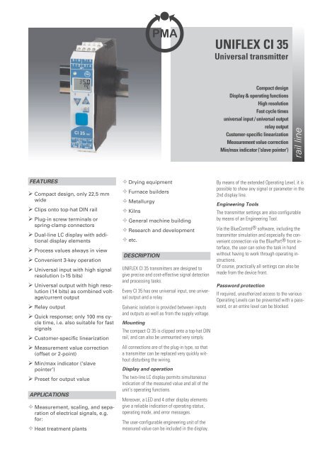
UNIFLEX CI 35 Universal Transmitter - Temp-Press Inc
UNIFLEX CI 35 Universal Transmitter - Temp-Press Inc
UNIFLEX CI 35 Universal Transmitter - Temp-Press Inc

Create successful ePaper yourself
Turn your PDF publications into a flip-book with our unique Google optimized e-Paper software.
<strong>UNIFLEX</strong> <strong>CI</strong> <strong>35</strong><br />
<strong>Universal</strong> transmitter<br />
Compact design<br />
Display & operating functions<br />
High resolution<br />
Fast cycle times<br />
universal input / universal output<br />
relay output<br />
Customer-specific linearization<br />
Measurement value correction<br />
Min/max indicator (‘slave pointer’)<br />
rail line<br />
FEATURES<br />
Compact design, only 22,5 mm<br />
wide<br />
Clips onto top-hat DIN rail<br />
Plug-in screw terminals or<br />
spring-clamp connectors<br />
Dual-line LC display with additional<br />
display elements<br />
Process values always in view<br />
Convenient 3-key operation<br />
<strong>Universal</strong> input with high signal<br />
resolution (>15 bits)<br />
<strong>Universal</strong> output with high resolution<br />
(14 bits) as combined voltage/current<br />
output<br />
Relay output<br />
Quick response; only 100 ms cycle<br />
time, i.e. also suitable for fast<br />
signals<br />
Customer-specific linearization<br />
Measurement value correction<br />
(offset or 2-point)<br />
Min/max indicator (‘slave<br />
pointer’)<br />
Preset for output value<br />
APPLICATIONS<br />
Measurement, scaling, and separation<br />
of electrical signals, e.g.<br />
for:<br />
Heat treatment plants<br />
Drying equipment<br />
Furnace builders<br />
Metallurgy<br />
Kilns<br />
General machine building<br />
Research and development<br />
etc.<br />
DESCRIPTION<br />
<strong>UNIFLEX</strong> <strong>CI</strong> <strong>35</strong> transmitters are designed to<br />
give precise and cost-effective signal detection<br />
and processing tasks.<br />
Every <strong>CI</strong> <strong>35</strong> has one universal input, one universal<br />
output and a relay.<br />
Galvanic isolation is provided between inputs<br />
and outputs as well as from the supply voltage.<br />
Mounting<br />
The compact <strong>CI</strong> <strong>35</strong> is clipped onto a top-hat DIN<br />
rail, and can also be unmounted very simply.<br />
All connections are of the plug-in type, so that<br />
a transmitter can be replaced very quickly without<br />
disturbing the wiring.<br />
Display and operation<br />
The two-line LC display permits simultaneous<br />
indication of the measured value and all of the<br />
unit’s operating functions.<br />
Moreover, a LED and 4 other display elements<br />
give a reliable indication of operating status,<br />
operating mode, and error messages.<br />
The user-configurable engineering unit of the<br />
measured value can be included in the display.<br />
By means of the extended Operating Level, it is<br />
possible to show any signal or parameter in the<br />
2nd display line.<br />
Engineering Tools<br />
The transmitter settings are also configurable<br />
by means of an Engineering Tool.<br />
Via the BlueControl® software, including the<br />
transmitter simulation and especially the convenient<br />
connection via the BluePort® front interface,<br />
the user can solve the task in hand<br />
without having to work through operating instructions.<br />
Of course, practically all settings can also be<br />
made from the device front.<br />
Password protection<br />
If required, unauthorized access to the various<br />
Operating Levels can be prevented with a password,<br />
or an entire level can be blocked.
TECHNICAL DATA<br />
Bild 2: Anschluss <strong>CI</strong> <strong>35</strong><br />
INP1<br />
OUT3<br />
PWR<br />
UNIVERSAL INPUT INP1<br />
Type: single ended, exept thermocouples<br />
Resolution:<br />
> 15 bits<br />
Decimal point: 0 to 3 decimals<br />
Digital input filter: adjustable 0.0...999.9 s<br />
Scanning cycle: 100 ms (only INP1)<br />
Linearization:<br />
31 segments, adaptable<br />
with BlueControl ®<br />
Measurement<br />
value correction: 2-point or offset<br />
Limiting frequency: 1.7 Hz<br />
Thermocouples (Table 1)<br />
Input resistance: ? 1M[<br />
Influence of source<br />
resistance:<br />
1 µV/[<br />
Input circuit monitor: sensor break, polarity<br />
Cold-junction compensation<br />
• Internal<br />
- additional error: typical ß_ 0.5 K<br />
max. ß +1.2 K<br />
• External:<br />
- value setting: 0 ...100 °C<br />
Break monitoring<br />
Sensor current: ß 1µA<br />
Operating sense configurable<br />
5<br />
1<br />
11<br />
15<br />
mV<br />
mA<br />
6<br />
2<br />
12<br />
16<br />
Resistance thermometer (Table 2)<br />
Connection technique: 3 or 4-wire<br />
Lead resistance: max. 30 [<br />
(max. at range end)<br />
Input circuit monitoring: break and short circuit<br />
Measurement span<br />
Separated into ranges<br />
Physical measurement range: 0...4,500 [<br />
The BlueControl® software enables the internal<br />
characteristic curve for the KTY 11-6 temperature<br />
sensor to be adapted.<br />
V<br />
L N<br />
~90-260V<br />
~24V<br />
7<br />
13<br />
V<br />
8<br />
3 4<br />
14<br />
17 18<br />
OUT1<br />
Table 1: Thermocouple input<br />
Thermocouple type Measurement range Error Typical resol.<br />
L Fe-CuNi (DIN) -100...900°C -148...1,652°F ß 2K 0.05 K<br />
J Fe-CuNi -100...1,200°C -148...2,192°F ß 2K 0.05 K<br />
K NiCr-Ni -100...1,<strong>35</strong>0° -148...2,462°F ß 2K 0.1 K<br />
N Nicrosil/Nisil -100...1,300°C -148...2,372°F ß 2K 0.1 K<br />
S PtRh-Pt 10% 0...1,760°C 32...3,200°F ß 2K 0.1 K<br />
R PtRh-Pt 13% 0...1,760°C 32...3,200°F ß 2K 0.1 K<br />
T** Cu-CuNi -200...400°C -328...752°F ß 2K 0.03 K<br />
C W5%Re-W26%Re 0...2,315°C 32...4,199°F ß 3K 0.2 K<br />
D W3%Re-W25%Re 0...2,315°C 32...4,199°F ß 3K 0.2 K<br />
E NiCr-CuNi -100...1,000°C -148...1,832°F ß 2K 0.05 K<br />
B* PtRh-Pt6% 0(400)...1,820°C 32(752)...3,308°F ß 3K 0.2 K<br />
Special -25…75mV ß 0.1% 0.005%<br />
* Values apply from 400°C upwards.<br />
**Values apply from -80°C upwards.<br />
Table 2: Resistive inputs<br />
Type Sensor current Measurement range Error Typical resol.<br />
Pt100 ***<br />
-200...100 (150)°C -328...212 (302)°F ß 1 K 0.05 K<br />
Pt100 -200...850°C -328...1,562°F ß 1 K 0.05 K<br />
Pt1000 -200...850°C -328...1,562°F ß 2 K 0.05 K<br />
KTY 11-6* -50...150°C -58...302°F ß 2 K 0.05 K<br />
Special* 0...4,500 [** ß 0.1% 0.005%<br />
ß 0.25mA<br />
Special 0...450 [** ß 0.1% 0.005%<br />
Potentiom. 0...160 [** ß 0.1% 0.005%<br />
Potentiom. 0...450 [** ß 0.1% 0.005%<br />
Potentiom. 0...1,600 [** ß 0.1% 0.005%<br />
Potentiom. 0...4,500 [** ß 0.1% 0.005%<br />
* Default setting is the characteristic for KTY 11-6 (-50...150°C)<br />
** <strong>Inc</strong>luding lead resistance<br />
*** up to 150 °C at reduced lead resistance (max. 160 [)<br />
Table 3: Current and voltage input<br />
Measurement range Input resistance Error Typical resol.(∅)<br />
0...10 V ~ 110 k[ ß 0.1 % 0.3 mV<br />
-10...10 V ~ 110 k[ ß 0.1 % 0.6 mV<br />
-5...5 V ~ 110 k[ ß 0.1 % 0.3 mV<br />
-2.5...115 mV* >1M[ ß 0.1 % 4 úV<br />
-25...1,150 mV* >1M[ ß 0.1 % 40 úV<br />
-25...90 mV* >1M[ ß 0.1 % 4 úV<br />
-500...500 mV* >1M[ ß 0.1 % 40 úV<br />
-200...200 mV* >1M[ ß 0.1 % 20 úV<br />
0...20 mA 20 [ ß 0.1 % 0.8 úA<br />
* high-impedance, without break monitoring<br />
Current and voltage measurement<br />
(Table 3)<br />
Span start and span: anywhere within the<br />
measurement range<br />
Scaling:<br />
freely selectable<br />
–1,999...9,999<br />
Input circuit monitoring<br />
(current):<br />
12.5% below span start<br />
(2 mA)<br />
OUTPUTS<br />
SURVEY OF OUTPUTS<br />
Output<br />
Purpose<br />
OUT1(relay) Limit contact, alarms, errors,<br />
status messages *<br />
OUT3 (logic) Same as OUT1<br />
OUT3<br />
(continuous)<br />
Analog output for display value, INP1,<br />
<strong>Transmitter</strong> supply 13V/22mA<br />
All logic signals can be ”OR-linked”.<br />
2 <strong>UNIFLEX</strong> <strong>CI</strong> <strong>35</strong>
RELAY OUTPUT OUT1<br />
Type:<br />
2 NO contact<br />
Max. contact rating: 500 VA, max. 250 V,<br />
max.2Aat48...62 Hz,<br />
resistive load<br />
Min. contact rating: 6V, 1 mA DC<br />
Switching<br />
cycles<br />
(electrical):<br />
for I=1A/2A: ? 800,000/500,000<br />
(at 250V AC, resistive load)<br />
Note:<br />
If the relay OUT1 is used to operate external contactors,<br />
these must be fitted with RC snubber circuits to<br />
manufacturer specifications to prevent excessive<br />
voltage peaks at switch-off.<br />
OUT3 AS UNIVERSAL OUTPUT<br />
Parallel current/voltage output with common ‘minus’<br />
terminal (combined use only in galvanically isolated<br />
circuits).<br />
Freely scalable<br />
Resolution:<br />
14 bits<br />
Dynamic response Output follows the<br />
input:<br />
(step change of input<br />
signal) T90:<br />
ß 540 ms<br />
Tracking error I/U: ß 2%<br />
Residual ripple: ß_1 %<br />
(rel. to range end) 0...130 kHz<br />
Current output<br />
0/4...20 mA, configurable.<br />
short circuit proof<br />
Dynamic range: -0.5...23 mA<br />
Load: ß 700 [<br />
Load effect: ß 0.02%<br />
Resolution: ß 1.5 µA<br />
Error: ß 0.1%<br />
Voltage output<br />
0/2...10V, configurable<br />
not continuous short-circuit proof<br />
Dynamic range: -0.15...11.5 V<br />
Load: ? 2k[<br />
Load effect: ß 0.06%<br />
Resolution:<br />
ß 0.75 mV<br />
Error: ß 0.1%<br />
Additional error when ß 0.09%<br />
using simultaneously<br />
the current output<br />
OUT3 as transmitter supply<br />
Output:<br />
22 mA / ? 13VDC<br />
OUT3 as logic signal<br />
Load ß 700 [ 0/ß 23 mA<br />
Load > 500 [<br />
0/> 13 V<br />
GALVANIC ISOLATION<br />
Between input and output:<br />
500 V AC; 1min<br />
Isolation:<br />
between in-/output against earth: ß 33VAC<br />
Fig. 3: Galvanic isolation<br />
FUNCTIONS<br />
Signal processing<br />
The selected input signal is converted into an<br />
analog output signal:<br />
• Measurement value correction (offset and<br />
2-point)<br />
• Scaling<br />
• 1st-order filter with adjustable parameters<br />
(bandwidth, see below)<br />
• Linearization with 31 segments<br />
• √x , with √-x=0<br />
• x 2<br />
Behaviour on sensor break/short<br />
circuit<br />
• Response of the analog output is selectable<br />
(upscale / downscale)<br />
• Preset substitute input value, can be<br />
disabled<br />
Min/max indicator (slave pointer)<br />
The minimum and maximum input values are<br />
stored in the <strong>CI</strong> <strong>35</strong>, and can be displayed by<br />
means of the keys D (minimum) and I (maximum).<br />
The values are resettable.<br />
Display of engineering units<br />
The engineering unit for the measured value<br />
can either be selected from a predefined list of<br />
standard units, or it can be defined by the user<br />
(BlueControl ® ). The unit appears in the second<br />
line of the display.<br />
FILTER<br />
power<br />
relay OUT1<br />
safety isolation<br />
functional isolation<br />
Fig. 4: Filter function<br />
x<br />
input INP1<br />
output OUT3<br />
The transmitter contains a 1st-order mathematical<br />
filter with adjustable time constant and<br />
bandwidth.<br />
The bandwidth is the adjustable tolerance range<br />
within which the filter is active above and<br />
below the process value. Measurement value<br />
changes in excess of the adjusted bandwidth<br />
are not filtered.<br />
LIMIT VALUE FUNCTIONS<br />
Max, Min or Max/Min monitoring with adjustable<br />
hysteresis.<br />
Monitored signals<br />
• Process value<br />
• Input 1<br />
Functions<br />
• Input value monitoring<br />
• Input value monitoring with storage<br />
• Signal changes / with storage<br />
• Reset via front panel<br />
• Alarm discriminator adjustable from<br />
0...9.999 seconds<br />
• Several limit values and alarm messages<br />
can be logically ”OR-linked”.<br />
• Limits can used as control signals.<br />
ALARMS<br />
Sensor break / short circuit<br />
Depending on the selected input type, the input<br />
circuit is monitored for break, short circuit, and<br />
reversed polarity.<br />
ERROR LIST<br />
Display of error messages, warnings, and stored<br />
limit value messages in the error list. Messages<br />
are stored, and can be reset manually.<br />
Possible elements in the error list:<br />
Sensor break, short circuit, incorrect polarity<br />
Stored limit values<br />
Heating current alarm<br />
Control loop alarm<br />
Fault during self-tuning<br />
E.g. Re-calibration warning (message is generated<br />
when a predefined operating time is reached)<br />
E.g. Maintenance interval for a switching device<br />
(message is generated when a predefined number<br />
of switching cycles is reached)<br />
Internal fault (RAM, EEPROM, ...)<br />
Galvanic isolation is provided between inputs and<br />
outputs as well as from the supply voltage<br />
(3-port-isolation).<br />
Test voltage:<br />
Between power supply and 2.3 kV AC, 1 min<br />
in-/outputs:<br />
output<br />
input<br />
Filterbandwidth b_F<br />
t<br />
<strong>UNIFLEX</strong> <strong>CI</strong> <strong>35</strong> 3
DISPLAY AND OPERATION<br />
Display<br />
LCD:<br />
dual-line plus additional display elements<br />
Upper line:<br />
4 digits, 7-segment LCD<br />
• for process value<br />
Lower line:<br />
5 digits, 14-segment LCD; configurable contents<br />
(via BlueControl®)<br />
• Engineering unit<br />
• Parameters<br />
• Extended Operating Level<br />
Additional display elements<br />
2 display elements (bars in the lower line of the<br />
LCD, identified as 1, 2, F, E)<br />
• Bars 1 and 2: OUT1 active<br />
• Bar E: Entry has been made in the error list<br />
LED:<br />
• Green = OK<br />
• Red = limit value Lim1 triggered<br />
• Red blinking = internal fault, configuration<br />
mismatch<br />
Operating functions<br />
Only three keys at the front of the <strong>CI</strong> <strong>35</strong> are<br />
used to operate process values, parameters,<br />
and configuration data. Different Operating Levels<br />
and selected parameters can be disabled<br />
by means of BlueControl®.<br />
POWER SUPPLY<br />
Depending on ordered version:<br />
AC supply<br />
Voltage:<br />
Frequency:<br />
Consumption:<br />
90...260 V AC<br />
48...62 Hz<br />
approx. 7 VA max.<br />
<strong>Universal</strong> supply 24 V UC*<br />
AC supply:<br />
18...30 V AC<br />
Frequency:<br />
48...62 Hz<br />
DC supply: 1<br />
8...31 V DC<br />
Consumption:<br />
approx. 4 VA/3 W max.<br />
Supply only from safety electrical low voltage<br />
(SELV).<br />
Behaviour with power failure<br />
Configuration and parameter settings:<br />
Permanent storage in EEPROM<br />
BLUEPORT® FRONT INTERFACE<br />
Connection to the transmitter front via a PC<br />
adapter (see ‘Accessories’). The BlueControl®<br />
software enables the <strong>CI</strong> <strong>35</strong> to be configured,<br />
parameters set, and operated.<br />
Fig. 5: Dimensions <strong>CI</strong> <strong>35</strong><br />
22.5<br />
(0.87”)<br />
ENVIRONMENTAL CONDITIONS<br />
Protection mode<br />
Front panel: IP 20<br />
Housing: IP 20<br />
Terminals: IP 20<br />
Permissible temperatures<br />
For specified accuracy: -10...55°C<br />
Warm-up time: < 20 minutes<br />
<strong>Temp</strong>erature effect: ß 0.05% / 10 K<br />
add. influence to<br />
cold junction compensation: ß 0.05% / 10 K<br />
Operating limits:<br />
Storage:<br />
-20...60°C<br />
-30...70°C<br />
Humidity<br />
Max. 95%, 75% yearly average, no condensation<br />
Shock and vibration<br />
Vibration test Fc (DIN EN 60068-2-6)<br />
Frequency:<br />
10...150 Hz<br />
Unit in operation: 1g or 0.075 mm<br />
Unit not in operation: 2g or 0.15 mm<br />
Shock test Ea (DIN EN 60068-2-27)<br />
Shock:<br />
15 g<br />
Duration:<br />
11 ms<br />
Electromagnetic compatibility<br />
Complies with EN 61 326-1 for continuous,<br />
unattended operation.<br />
Interference radiation:<br />
• Within the limits for Class B devices.<br />
Immunity to interference:<br />
117.5 (4.63”)<br />
5 6 7 8<br />
111 (4.37”)<br />
Klemme /<br />
terminal<br />
1516 17 18<br />
Meets the test requirements for devices in industrial<br />
areas.<br />
Evaluation criteria:<br />
• Surge interference partly has marked effects,<br />
which decay after the interference stops.<br />
• With high levels of surge interference on 24 V<br />
AC mains leads, it is possible that the device<br />
is reset.<br />
• With HF interference, effects up to 50 µV can<br />
occur.<br />
GENERAL<br />
1 2 3 4<br />
Klemme /<br />
terminal<br />
5.5<br />
(0.20”)<br />
11 12 13 14<br />
Housing front<br />
Material: Polyamide PA 6.6<br />
Flammability class: VO (UL 94)<br />
Connecting terminals<br />
Material:<br />
Polyamide PA<br />
Flammability class: V2 (UL 94)<br />
for screw terminals<br />
V0 (UL 94) for<br />
spring-clamp terminals<br />
bus connector<br />
Electrical safety<br />
Complies with EN 61010-1:<br />
Over-voltage category II<br />
Contamination degree 2<br />
Protection class II<br />
2.3<br />
(0.08”)<br />
99 (3.90”)<br />
Electrical connections<br />
Plug-in connector strips with choice of terminal<br />
type:<br />
• Screw terminals or spring-clamp terminals,<br />
both for lead cross-sections from 0.2 to 2.5<br />
mm 2 . (AWG24-12)<br />
.<br />
4 <strong>UNIFLEX</strong> <strong>CI</strong> <strong>35</strong>
Mounting method<br />
Clip-on rail mounting (<strong>35</strong> mm top-hat rail to EN<br />
50 022). Locked by means of metal catch in<br />
housing base.<br />
Close-packed mounting possible.<br />
Mounting position: vertical<br />
Weight: 0.18 kg<br />
CERTIFICATION<br />
• CE certified<br />
• UL / cUL certified (applied for)<br />
ACCESSORIES<br />
BlueControl® (Engineering Tool)<br />
PC program for configuring, parameter setting,<br />
and operating (commissioning) the <strong>CI</strong> <strong>35</strong> transmitter.<br />
Moreover, all settings are saved and<br />
can be printed, if required.<br />
Depending in version, a powerful data acquisition<br />
module with trend graphics is available.<br />
Show/hide function<br />
The BlueControl® software enables any number<br />
of parameters and configuration setting to<br />
be shown/hidden.<br />
This ensures that only permitted parameters &<br />
settings can be changed in the transmitter. Safety-relevant<br />
parameters are not displayed.<br />
Simulation function<br />
The built-in simulation serves to test the settings.<br />
Import function<br />
Engineerings of <strong>UNIFLEX</strong> <strong>CI</strong>/CB created by engineering<br />
tool ET/Uniflex can be read and<br />
transformed if possible.<br />
Software requirements:<br />
Windows 95/98/NT/2000/XP<br />
Configuration settings made only via the Blue-<br />
Control® software (not via the transmitter’s<br />
front keys)<br />
• Customer-specific linearization<br />
• Switch-over to 60 Hz mains frequency<br />
• Blocking operator functions, Operating<br />
Levels, and password definition<br />
• Text setting<br />
• Definition of the display contents<br />
Table 4: BlueControl®, versions und functions:<br />
Functionality Mini Basic Expert<br />
parameter and configuration setting<br />
yes yes yes<br />
download: writes an engineering to the device<br />
yes yes yes<br />
online-mode / visualisation<br />
SIM only yes yes<br />
creation of user defined linearizations<br />
yes yes yes<br />
configuration of extended operation level<br />
yes yes yes<br />
upload: reads an engineering from the device<br />
SIM only yes yes<br />
basic diagnosis function<br />
no no yes<br />
saves files and engineering data<br />
no yes yes<br />
printer function<br />
no yes yes<br />
online documentation / help system<br />
yes yes yes<br />
measurement correction (calibration procedure)<br />
yes yes yes<br />
data acquisition and trend function<br />
SIM only yes yes<br />
personal assistant function yes yes yes<br />
Hardware requirements:<br />
A special PC adapter (see ‘Accessories’) is required<br />
for connecting to the transmitter.<br />
Updates and demo software from:<br />
www.pma-online.de<br />
Standard accessories:<br />
• Operating notes<br />
<strong>UNIFLEX</strong> <strong>CI</strong> <strong>35</strong> 5
ORDERING INFORMATION<br />
<strong>Transmitter</strong> <strong>UNIFLEX</strong> <strong>CI</strong> <strong>35</strong><br />
1 universal-input<br />
®<br />
with display and BluePort -interface<br />
C I 3 5 1 0 0 0<br />
0<br />
00<br />
without plug-in connector terminals<br />
with screw-terminal connectors<br />
with spring-clamp terminals<br />
90..260V AC, mA/V/logic +1 relay<br />
2<br />
18...30VAC/18..31VDC, mA/V/logic +1 relay 3<br />
Standard configuration 0<br />
Configuration to order 9<br />
Standard (CE-certified) 0<br />
UL /cUL - certified (applied for)<br />
U<br />
0<br />
1<br />
2<br />
Fig. 6: Accessory parts<br />
ACCESSORIES<br />
Description Quantity Order no.<br />
1 Connector set with screw terminals 4 pieces 9407-998-07101<br />
2 Connector set with spring-clamp terminals 4 pieces 9407-998-07111<br />
2<br />
1<br />
ADDITIONAL ACCESSORIES<br />
Description Language Order no.<br />
®<br />
PC adapter for the BluePort front interface 9407-998-00001<br />
USB serial adaptor (USB to RS 232) 9407-998-00081<br />
®<br />
BlueControl Mini German/English www.pma-online.de<br />
®<br />
BlueControl with Basic license rail line German/English 9407-999-12001<br />
®<br />
BlueControl with Expert license rail line German/English 9407-999-12011<br />
Please also order the associated documentation:<br />
Description<br />
Order no.<br />
Operating instructions for <strong>CI</strong> <strong>35</strong> (D) 9499-040-71718<br />
Operating instructions for <strong>CI</strong> <strong>35</strong> (E) 9499-040-71711<br />
PMA<br />
Prozeß- und Maschinen- Automation GmbH<br />
P.O. Box 31 02 29<br />
D-34058 Kassel<br />
Tel.: +49 - 561- 505 1307<br />
Fax: +49 - 561- 505 1710<br />
E-mail: mailbox@pma-online.de<br />
Internet: http://www.pma-online.de<br />
Your local representative<br />
Printed in Germany - Edition 07/2006- Subject to change without notice - 9498 737 53413