View Catalogue (265 KB) - Process Pump Sales Inc
View Catalogue (265 KB) - Process Pump Sales Inc
View Catalogue (265 KB) - Process Pump Sales Inc

You also want an ePaper? Increase the reach of your titles
YUMPU automatically turns print PDFs into web optimized ePapers that Google loves.
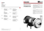
Transfer Gear <strong>Pump</strong>s BT, BTH
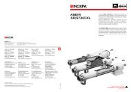
Construction of the Gear <strong>Pump</strong>s BT, BTH<br />
Basic construction of BT (rear bearing cover removed)<br />
Housing<br />
Driving shaft<br />
Shaft sealing by packed gland<br />
Stuffing-box cover<br />
Gearing with journals<br />
Transfering medium inlet or outlet<br />
Basic construction of BTH (rear bearing cover removed)<br />
Heating liquid outlet<br />
Housing<br />
Heating chamber<br />
Driving shaft<br />
Shaft sealing by packed gland<br />
<strong>Pump</strong>ing chamber<br />
Stuffing-box cover<br />
Gearing with journals<br />
Transfering medium inlet or outlet<br />
Heating liquid inlet<br />
(left or right optional)<br />
2<br />
KRACHT GmbH · Postbox 1420/1440 · D-58774 Werdohl · Phone 0049 (23 92) 935-0 · Fax 0049 (23 92) 935 209 · Internet: www.kracht-hydraulik.de · e-mail: info@kracht-hydraulik.de
Description<br />
<strong>Pump</strong> series BT and BTH are low speed gear pumps for<br />
transfering medium and high viscosity fluids, provided they<br />
have certain minimum amount of lubricating property, do<br />
not contain any solids and are chemically compatable with<br />
the materials of construction.<br />
The standard material of construction for housing, bearing<br />
cover and stuffing box cover is grey cast iron. The shafts<br />
and gears are manufactured from case hardening steel, hardened<br />
and ground. The shafts are carried in plain bearings<br />
manufactured in bronze, with an option of sintered iron.<br />
The rotary shaft seal is a packed gland consisting of PTFE<br />
fillied Aramid yarn, and the static sealing between mating<br />
parts is by means of either, liquid sealant or gaskets. All<br />
sealing materials are asbestos free.<br />
External axial loads are not permissable, restricted radial<br />
loads can be absorbed, dependant on their magnetude and<br />
direction.<br />
Driving by flexible shaft coupling is preferred.<br />
In the case of fluids which require elevated temperatures to<br />
flow i. e. bitumen, wax etc. the BTH series pump should be<br />
used. In this model the housing is double walled to provide<br />
a heating jacked. The pump transfer chamber is heated by<br />
circulating heat transfer fluid or steam through the jacket.<br />
The standard range of models is complimented by a range<br />
of a special models described below.<br />
The pump size BT2 can be supplied in a corrosion and acid<br />
- resistant construction (stainless steel body and gear) with<br />
carbone plain bearings bushes; the operating pressure of<br />
this pump is limited to 5 bars.<br />
BT1 up to BT4 pumps can be manufactured with bronze<br />
housing and with further combinations of stainless steel<br />
gears and shafts or bronze gears and stainless steel shafts.<br />
For use on liquids with an abrasive nature and high corrosive<br />
effects like resins, certain paints and varnishes as<br />
well as glues a special construction, Code No. / 04, is<br />
recommended, which is available for pump sizes BT1 up<br />
to BT7.<br />
In this model all pump parts which are in contact with the<br />
transfering fluid are protected from wear and corrosion by<br />
a chemically deposited Ni/SiC- dispersion layer. This treatment<br />
substantially extends the service life compared<br />
with that of a standard model when used in these types of<br />
fluid.<br />
KRACHT GmbH · Postbox 1420/1440 · D-58774 Werdohl · Phone 0049 (23 92) 935-0 · Fax 0049 (23 92) 935 209 · Internet: www.kracht-hydraulik.de · e-mail: info@kracht-hydraulik.de<br />
3
Characteristics<br />
General Characteristics<br />
Mounting<br />
Foot-Mounting<br />
Pipe Connection BT: Whitworth-Pipe thread<br />
BTH: Whitworth-Pipe thread Flange,<br />
Flange with counterflange<br />
Direction of Rotation BT = Clockwise and Anticlockwise<br />
BTH = Clockwise or Anticlockwise<br />
Weight see page 8 ... 11<br />
Fitting Position<br />
horizontal<br />
Permissible Ambient ϑ u min = - 10 °C<br />
Temperature Range ϑ u max = 60 °C<br />
Operating Characteristics<br />
Operating Pressures<br />
Suction Side p e min = - 0.4 bar<br />
Pressure Side * p N = 8 bar<br />
1 bar to BT0<br />
5 bar to BT2 Stainless Steel<br />
max. pressure in the heating jacket p H = 10 bar<br />
Temperature Range ϑ m min = - 10 °C<br />
ϑ m max = 220 °C<br />
Viscosity Range ν min = 76 mm 2 /s<br />
ν max = 30 000 mm 2 /s<br />
Viskosities other than within this range on request<br />
Discharge Flow see table page 6, 7<br />
Power input Speeds n min = 100 1/min<br />
n max = 750 1/min<br />
Mediums, suitable to be operated<br />
Lubricating-, Cutting Oils Waste Oils Adhesives, Plastics Cellulose<br />
Soluble-, Steel Hardening-, Bitumen Binding Agents etc.<br />
Rolling-, Drawing Oils Paints Resins<br />
Diesel Oils Greases Glue, Glue Liquors<br />
Fuel Oil S Synthetic-Resin Varnishes Molasses<br />
Engine Oils Nitrocellulose Lacquers Waxes<br />
Other Types<br />
DM <strong>Pump</strong> with electric motor, Coupling and Coupling guard mounted on a common base plate.<br />
Accessories<br />
Flexible Coupling<br />
* higher operating pressure on request<br />
4<br />
KRACHT GmbH · Postbox 1420/1440 · D-58774 Werdohl · Phone 0049 (23 92) 935-0 · Fax 0049 (23 92) 935 209 · Internet: www.kracht-hydraulik.de · e-mail: info@kracht-hydraulik.de
Type Key and Ordering Code<br />
Direction<br />
of rotation<br />
Pipe<br />
connection<br />
Construction of housing<br />
and friction bearing<br />
Construction<br />
of gear unit<br />
Kind of sealing<br />
(Packing)<br />
R clockwise<br />
L anticlockwise<br />
B clockwise<br />
and<br />
anticlockwise<br />
Z<br />
F<br />
Whitworth<br />
pipe thread<br />
Flange<br />
G Flange with<br />
counter flange<br />
A<br />
B<br />
C<br />
U<br />
R<br />
cast iron<br />
without bearing bush<br />
cast iron with Bz bearing bush<br />
iron bearing bush<br />
Bronze without bearing bush<br />
Stainless steel with carbonbearing<br />
bush<br />
(material No. 1.4308)<br />
C<br />
K<br />
F<br />
S<br />
T<br />
Steel shafts and gear<br />
unhardened<br />
Steel shafts and gear<br />
hardened<br />
Stainless steel shaft<br />
(material No. 1.4057)<br />
bronze gear<br />
Stainless steel shafts and<br />
gear heat treated<br />
(material No. 1.4057)<br />
51 Arolan<br />
Model with heating jacket<br />
Cylindrical shaft end without<br />
step bearing, with<br />
packing and threaded pipe<br />
connection<br />
BT 0 BZ OAC 51 / •<br />
BT 2 BZ ORT 51 / •<br />
BT 1...4 BZ OU S T 51 / •<br />
BT 1...7 BZ O B CK 51 / •<br />
BT 1...7 BZ OCK 51 / 04<br />
Code No. for special<br />
constructions<br />
04 Wear and corrosion<br />
protected model<br />
BTH 1 + 2<br />
BTH 3<br />
R<br />
L • O B CK 51<br />
R<br />
L • O B CF 51<br />
Model with heating jacket<br />
Cylindrical shaft end without<br />
step bearing, with packing,<br />
threated pipe- or flange<br />
connection<br />
KRACHT GmbH · Postbox 1420/1440 · D-58774 Werdohl · Phone 0049 (23 92) 935-0 · Fax 0049 (23 92) 935 209 · Internet: www.kracht-hydraulik.de · e-mail: info@kracht-hydraulik.de<br />
5
Characteristic Data<br />
<strong>Pump</strong> type<br />
Viscosity ν (mm 2 /s)<br />
Viscosity ν (mm 2 /s)<br />
Viscosity ν (mm 2 /s)<br />
reg. power input P (kW)<br />
reg. power input P (kW)<br />
reg. power input P (kW)<br />
BT 0<br />
BT 1<br />
BT 2<br />
BT 3<br />
BT 4<br />
BT 5<br />
BT 6<br />
BT 7<br />
BTH 1/55<br />
BTH 1/105<br />
BTH 2/100<br />
BTH 2/130<br />
BTH 3/150<br />
Power input required at high viscosities<br />
Viscosities above values specified in the table require a higher power<br />
input.<br />
In such cases the power input of the pump P 1Pu can be determined by<br />
means of the viscosity factor f ν (see table page 7) as follows:<br />
P 1Pu = P Tab 76 + f ν · Q Tab<br />
For example: BT 4 n = 200 1/min; ν = 10 000 mm 2 /s; p = 8 bar with<br />
P tab 76 = 0,6 kW, table data at ν = 76 mm 2 /s<br />
f ν = 27 x 10 -3 kW min/l<br />
Q Tab = 32 l/min<br />
gives power input P 1Pu = 1,46 kW<br />
6<br />
KRACHT GmbH · Postbox 1420/1440 · D-58774 Werdohl · Phone 0049 (23 92) 935-0 · Fax 0049 (23 92) 935 209 · Internet: www.kracht-hydraulik.de · e-mail: info@kracht-hydraulik.de
Characteristic Data<br />
<strong>Pump</strong> type<br />
Viscosity ν (mm 2 /s)<br />
Viscosity ν (mm 2 /s)<br />
Viscosity ν (mm 2 /s)<br />
Viscosity ν (mm 2 /s)<br />
reg. power input P (kW)<br />
reg. power input P (kW)<br />
reg. power input P (kW)<br />
reg. power input P (kW)<br />
BT 0<br />
BT 1<br />
BT 2<br />
BT 3<br />
BT 4<br />
BT 5<br />
BT 6<br />
BT 7<br />
BTH 1/55<br />
BTH 1/105<br />
BTH 2/100<br />
BTH 2/130<br />
BTH 3/150<br />
kin. viscosity<br />
ν < 1000 2000 3000 6000 10000 20000 30000<br />
mm 2 /s<br />
max. speed<br />
n max ≥ 750 600 500 400 300 200 100<br />
1/min<br />
visc.-factor<br />
f ν 9,5 14 17 22,5 27 34 38<br />
10 -3 kW min/l<br />
Spread of output:<br />
± 5% of table values Q. Viscosities below<br />
76 mm 2 /s effect a decrease of output flow<br />
values, Q.<br />
The power output of driving motor must<br />
exceed the table values P by about 20%.<br />
Important:<br />
When determining the power input required<br />
always consider the max. operating<br />
viscosity.<br />
(e.g. in the starting situation)!<br />
KRACHT GmbH · Postbox 1420/1440 · D-58774 Werdohl · Phone 0049 (23 92) 935-0 · Fax 0049 (23 92) 935 209 · Internet: www.kracht-hydraulik.de · e-mail: info@kracht-hydraulik.de<br />
7
Dimensions<br />
BT 0 BZ OAC 51<br />
BT 1...7 BZ O.. 51<br />
BT 1...7 BZ OCK 51/04<br />
Groove for retaining ring acc. to standard<br />
DIN 471<br />
Parallel key acc. to DIN 6885<br />
<strong>Pump</strong> type R A B C D øE F G H O J K P<br />
Shaft end<br />
approx.<br />
ød l m n u t d 1 l<br />
Z weight<br />
1<br />
kg<br />
BT 0 G 1 ⁄4 30 60 45 65 11 15 65 60 47 38 95 88 13 22 – – – – – – 11 2<br />
BT 1 G 1 ⁄2 – 45 55 75 9 12 85 69 54 48 150 100 13 40 15 10 5 15 M6 15 20 3<br />
BT 2 G 3 ⁄4 35 55 65 90 10 12 90 88,5 71 65 165 125 15 45 25 5 5 17 M6 15 20 5<br />
BT 3 G 1 40 65 85 105 10 12 100 111 88,5 70 190 155 18 50 30 5 6 20,5 M6 15 23 7<br />
BT 4 G 1 1 ⁄2 40 80 95 135 10 12 130 131,5 100 102 245 189 25 50 40 5 8 28 M8 20 28 15<br />
BT 5 G 1 1 ⁄2 35 75 140 180 14 20 150 145 103 98 250 213 25 50 40 5 8 28 M8 20 29 20<br />
BT 6 G 2 35 75 185 225 14 28 175 175 126 106 245 252 25 50 40 5 8 28 M8 20 29 29<br />
BT 7 G 2 60 100 185 225 14 28 240 175 126 123 260 252 25 50 40 5 8 28 M8 20 29 37<br />
Inlet and outlet ports equally sized<br />
8<br />
KRACHT GmbH · Postbox 1420/1440 · D-58774 Werdohl · Phone 0049 (23 92) 935-0 · Fax 0049 (23 92) 935 209 · Internet: www.kracht-hydraulik.de · e-mail: info@kracht-hydraulik.de
Dimensions<br />
BTH 1 /<br />
55<br />
105 • Z O • K 51<br />
Outlet port for heating liquids **<br />
Parallel key acc. to DIN 6885<br />
Inlet port for heating liquids<br />
clockwise or anticlockwise by choice<br />
unused connection is to be sealed<br />
BTH 1 /<br />
55<br />
105 • F O • K 51<br />
Outlet port for heating liquids **<br />
Parallel key acc. to DIN 6885<br />
Inlet port for heating liquids<br />
clockwise or anticlockwise by choice<br />
unused connection is to be sealed<br />
BTH 1 /<br />
55<br />
105 • G O • K 51<br />
Outlet port for heating liquids **<br />
Counterflange: Flange C 15 x 21,3 DIN 2633<br />
approx. Weight (kg)<br />
BTH 1/ 55 = 45 kg<br />
Z; F<br />
1/105 = 46 kg<br />
BTH 1/ 55 = 48 kg<br />
G<br />
1/105 = 49 kg<br />
** Dimensions correspond to mounting<br />
surface of inlet port for heating liquids<br />
Parallel key acc. to DIN 6885<br />
Counterflange: Welding flange acc. to B. 009 695 0002<br />
Inlet port for heating liquids<br />
Blank flange B 15 ND 16 DIN 2527<br />
(finished)<br />
Counterflange: Flange C 15 x 21,3 DIN 2633<br />
(finished) clockwise or anticlockwise by choice<br />
unused connection is to be sealed<br />
KRACHT GmbH · Postbox 1420/1440 · D-58774 Werdohl · Phone 0049 (23 92) 935-0 · Fax 0049 (23 92) 935 209 · Internet: www.kracht-hydraulik.de · e-mail: info@kracht-hydraulik.de<br />
9
Dimensions<br />
BTH 2 /<br />
100<br />
130 • Z O • K 51<br />
Outlet port for heating liquids **<br />
Parallel key acc. to DIN 6885<br />
Inlet port for heating liquids<br />
clockwise or anticlockwise by choice<br />
unused connection is to be sealed<br />
BTH 2 /<br />
100<br />
130 • F O • K 51<br />
Outlet port for heating liquids **<br />
Parallel key acc. to DIN 6885<br />
BTH 2 /<br />
100<br />
130 • G O • K 51<br />
Inlet port for heating liquids<br />
clockwise or anticlockwise by choice<br />
unused connection is to be sealed<br />
Outlet port for heating liquids **<br />
Counterflange: Flange C 20 x 26,9 DIN 2633<br />
approx. Weight (kg)<br />
BTH 2/100 = 84 kg<br />
Z; F<br />
2/130 = 85 kg<br />
BTH 2/100 = 93 kg<br />
G<br />
2/130 = 94 kg<br />
** Dimensions correspond to mounting<br />
surface of inlet port for heating liquids<br />
Parallel key acc. to DIN 6885<br />
Counterflange: Flange C 50 x 60,3 DIN 2633 (finished)<br />
Blank flange B 20 ND 16 DIN 2527<br />
(finished)<br />
Inlet port for heating liquids<br />
Counterflange: Flange C 20 x 26,9 DIN 2633<br />
(finished) clockwise or anticlockwise by choice<br />
unused connection is to be sealed<br />
10<br />
KRACHT GmbH · Postbox 1420/1440 · D-58774 Werdohl · Phone 0049 (23 92) 935-0 · Fax 0049 (23 92) 935 209 · Internet: www.kracht-hydraulik.de · e-mail: info@kracht-hydraulik.de
Dimensions<br />
BTH 3 / 150 • Z O • F 51<br />
Outlet port for heating liquids **<br />
Parallel key acc. to DIN 6885<br />
Inlet port for heating liquids<br />
clockwise or anticlockwise by choice<br />
unused connection is to be sealed<br />
BTH 3 / 150 • F O • F 51<br />
Outlet port for heating liquids **<br />
Parallel key acc. to DIN 6885<br />
Inlet port for heating liquids<br />
BTH 3 / 150 • G O • F 51<br />
clockwise or anticlockwise by choice<br />
unused connection is to be sealed<br />
Outlet port for heating liquids **<br />
Counterflange: Flange C 25 x 33,7 DIN 2633<br />
approx. Weight (kg)<br />
BTH 3/150 Z; F = 142 kg<br />
BTH 3/150 G = 155 kg<br />
** Dimensions correspond to mounting<br />
surface of inlet port for heating liquids<br />
Parallel key acc. to DIN 6885<br />
Counterflange: Flange C 80 x 88,9 DIN 2633 (finished)<br />
Blank flange B 25 ND 16 DIN 2527<br />
(finished)<br />
Inlet port for heating liquids<br />
Counterflange: Flange C 25 x 33,7 DIN 2633<br />
(finished) clockwise or anticlockwise by choice<br />
unused connection is to be sealed<br />
KRACHT GmbH · Postbox 1420/1440 · D-58774 Werdohl · Phone 0049 (23 92) 935-0 · Fax 0049 (23 92) 935 209 · Internet: www.kracht-hydraulik.de · e-mail: info@kracht-hydraulik.de<br />
11
Overview of<br />
our complete<br />
program<br />
Transfer pumps<br />
Volutronic ®<br />
Mobile hydraulics<br />
Industrial hydraulics<br />
Transfer pumps for lubricating<br />
oil supply equipment,<br />
low pressure filling and feed<br />
systems, dosing and mixing<br />
systems.<br />
Gear flow meters and electronics<br />
for volume and<br />
flow metering technology in<br />
hydraulics, processing and<br />
laquering technology.<br />
Single and multistage<br />
high pressure gear pumps,<br />
hydraulic motors and valves for<br />
construction machinery,<br />
lorry-mounted machines.<br />
Cetop directional control<br />
and proportional valves,<br />
hydraulic cylinders, pressure,<br />
quantity and stop valves<br />
for pipe and slab construction,<br />
hydraulic accessories<br />
for industrial hydraulics<br />
(mobile and stationary use).<br />
With our decades of<br />
experience, we are at your<br />
side, world-wide, for the<br />
professional mastery of<br />
specific applications and<br />
complete solutions in<br />
hydraulics and<br />
process technology.<br />
BT/BTH.e.10.99<br />
KRACHT GmbH · Postbox 1420/1440 · D-58774 Werdohl · Phone 0049 (23 92) 935-0 · Fax 0049 (23 92) 935 209 · Internet: www.kracht-hydraulik.de · e-mail: info@kracht-hydraulik.de