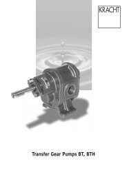
Pressure Relief Valves HV, HVF - Process Pump Sales Inc
Pressure Relief Valves HV, HVF - Process Pump Sales Inc
Pressure Relief Valves HV, HVF - Process Pump Sales Inc

You also want an ePaper? Increase the reach of your titles
YUMPU automatically turns print PDFs into web optimized ePapers that Google loves.
Construction of the <strong>Pressure</strong> <strong>Relief</strong> <strong>Valves</strong> <strong>HV</strong>, <strong>HV</strong>FSymbol1 Housing2 Main Sliding Piston3 Compression Spring4 Pilot Sliding Piston5 Compression Spring6 Set Screw7 Bleeding Screw8 Protective Cap2KRACHT GmbH · Gewerbestr. 20 · D-58791 Werdohl · Tel. 0 23 92/935-0 · Fax 0 23 92/935 209 · Internet: www.kracht-hydraulik.de · e-mail: info@kracht-hydraulik.de
DescriptionThe pilot operated, sliding piston <strong>Pressure</strong> <strong>Relief</strong> Valve<strong>HV</strong>/<strong>HV</strong>F is intended for inline mounting and is suitable tosafeguard mean pressure hydraulic circuits up to 160 bars.The pipe connection is to be effected either by SAE-MountingSurfaces (3000 psi) or by Whitworth Pipe Threads “G”.Due to the design principle of sliding piston piloting thevalve is also suitable for higher viscosities.Valve Construction:Main Valve StageThe Main Sliding Piston 2 is pressed against the AnnulatedArea a by the Compression Spring 3. The Valve Chamber blocated before the Main Sliding Piston 2 as well as the ValveChamber c to be found behind the Main Sliding Piston 2 aredirectly connected with the pilot valve.Pilot ValveThe Pilot Sliding Piston 4 is loaded by the CompressionSpring 5 and is balanced by the operating pressure p actingon the Annulated Area d. As soon as the spring force isexceeded by the operating pressure p the connection behindthe Main Sliding Piston 2 is blocked and the Valve Chamberc is then connected with the reservoir via the Bore e withinthe Pilot Sliding Piston 4. In this way it is guaranteed that, assoon as the set pressure is reached, the Main Sliding Piston2 releases the oil flow to the reservoir without any vibrationsmaintaining the operating pressure as adjusted by the SetScrew 6. The Spring chamber of the pilot valve can be bleededby the Bleeding Screw 7 provided the valve is installed invertical fitting position i.e. with the pressure setting arrangementup.KRACHT GmbH · Gewerbestr. 20 · D-58791 Werdohl · Tel. 0 23 92/935-0 · Fax 0 23 92/935 209 · Internet: www.kracht-hydraulik.de · e-mail: info@kracht-hydraulik.de 3
Characteristic Curves∆p = f (Q)Viscosity = 34 mm 2 /s<strong>HV</strong> 10 <strong>HV</strong>F 25<strong>HV</strong>F 40 <strong>HV</strong>F 50<strong>HV</strong>F 80KRACHT GmbH · Gewerbestr. 20 · D-58791 Werdohl · Tel. 0 23 92/935-0 · Fax 0 23 92/935 209 · Internet: www.kracht-hydraulik.de · e-mail: info@kracht-hydraulik.de 5
Type KeyNominal Size 10<strong>Pressure</strong> <strong>Relief</strong> Valvepilot operatedPipe Connectionby Threaded Ports G 1 ⁄2Panel MountingOptionNominal SizeQ max 50 l/minType of <strong>Pressure</strong> SettingA Set ScrewB KnobExample<strong>HV</strong> M . 10 A 1G 1 B 160Valve TypeDesign Serial No.Specified by KRACHT<strong>Relief</strong> Port G 1 ⁄4OptionModelsA Standard-TypeC Viton-Type<strong>Pressure</strong> Setting Ranges03 0.5 ...... 3 bars12 1 ...... 12 bars40 1 ...... 40 bars160 10 ......160 barsmeans:<strong>Pressure</strong> <strong>Relief</strong> Valve, Pilot Operated. For Panel Mounting,Nominal Size 10 (Q max 50 l/min), Standard Type, withThreaded Ports G 1 ⁄2, <strong>Pressure</strong> Setting by Knob, <strong>Pressure</strong>Setting Range: 10 up to 160 bars6KRACHT GmbH · Gewerbestr. 20 · D-58791 Werdohl · Tel. 0 23 92/935-0 · Fax 0 23 92/935 209 · Internet: www.kracht-hydraulik.de · e-mail: info@kracht-hydraulik.de
Type KeyNominal Size 25…80<strong>Pressure</strong> <strong>Relief</strong> Valvepilot operated, flange typePanel Mounting(NS 25/40 only)OptionNominal Size25 Q max 120 l/min40 Q max 350 l/min50 Q max 500 l/min80 Q max 750 l/minPipe Connection2F by SAE-Flanges1G by Threaded PortsType of <strong>Pressure</strong> SettingA Set ScrewB KnobExample<strong>HV</strong>F … E 50 A 1G 1 B 80Valve TypeDesign Serial No.Specified by KRACHT<strong>Relief</strong> Port G 1 ⁄4OptionModelsA Standard-TypeC Viton-Type<strong>Pressure</strong> Setting Ranges03 0.5 ...... 3 bars12 1 ...... 12 bars40 1 ...... 40 bars80 10 ...... 80 bars p max NG 50/80160 10 ......160 bars p max NG 25/40means:<strong>Pressure</strong> <strong>Relief</strong> Valve, Pilot Operated. Flange Type with<strong>Relief</strong> Port G 1 / 4 . Nominal Size 50 (Q max 500 l/min), StandardType, with Threaded Ports, <strong>Pressure</strong> Setting by Knob,<strong>Pressure</strong> Setting Range: 10 up to 80 bars8KRACHT GmbH · Gewerbestr. 20 · D-58791 Werdohl · Tel. 0 23 92/935-0 · Fax 0 23 92/935 209 · Internet: www.kracht-hydraulik.de · e-mail: info@kracht-hydraulik.de
DimensionsOrdering Code <strong>HV</strong>F . . 2F 1 A . Ordering Code <strong>HV</strong>F . . 1G 1 A .* ** <strong>Relief</strong> Port for Type <strong>HV</strong>FENom. SAE Thread WrenchWeightsize Flange R SizeA B C D E F G H K L M N kg25 1˝ G 1 52.4 26.2 M 10 59 70 26 20 50 75 200 55 Ø 55 24 3.440 1 1 ⁄2˝ G 1 1 ⁄2 69.9 35.7 M 12 83 94 39 20 65 95 220 65 Ø 75 36 6.750 2˝ G 2 77.8 42.9 M 12 97 102 50 20 75 105 240 75 Ø 90 30 10.980 3˝ G 3 106.4 61.9 M 16 131 135 78 25 110 125 280 110 Ø 105 40 18.1KRACHT GmbH · Gewerbestr. 20 · D-58791 Werdohl · Tel. 0 23 92/935-0 · Fax 0 23 92/935 209 · Internet: www.kracht-hydraulik.de · e-mail: info@kracht-hydraulik.de 9
DimensionsOrdering Code<strong>HV</strong>FM . . 2F 1 A .<strong>HV</strong>FM . . 1G 1 A .Ordering Code<strong>HV</strong>FM . . 2F 1 B .<strong>HV</strong>FM . . 1G 1 B .*** <strong>Relief</strong> Port for Type <strong>HV</strong>FENom. SAE ThreadSize Flange RA B C D E F G H K L 1 L 2 M N O S25 1˝ G 1 52.4 26.2 M 10 59 70 26 20 50 75 200 229 55 Ø 55 55 6040 1 1 ⁄2˝ G 1 1 ⁄2 69.9 35.7 M 12 83 94 39 20 65 95 220 246 65 Ø 75 55 60WrenchSizeP Weightkg24 M 40 x1.5 3.436 M 40 x1.5 6.7Drawing for Dimensions A, B, C, E, F, G, H, K see Page 10Accessories / Ordering Code <strong>HV</strong>FM 40 A 2F 1 A 60 + 2 x CFS 106-STWelding Flange SAE (3000 psi)Ordering SAECode FlangeO-Ring WeightA B C D F G H I L M kgCFS 102-ST 1˝ 34.5 25 38 18 14 M 10 71 52.4 53 26.2 4131 0.6CFS 106-ST 1 1 ⁄2˝ 48.6 38 44 25 18 M 12 94 70,0 77 35.7 4187 1.2CFS 108-ST 2˝ 61,0 50 45 25 18 M 12 103 77.8 89 42.9 4225 1.5CFS 112-ST 3˝ 89,0 73 50 27 23 M 16 135 106.4 124 62,0 4337 2.7KRACHT GmbH · Gewerbestr. 20 · D-58791 Werdohl · Tel. 0 23 92/935-0 · Fax 0 23 92/935 209 · Internet: www.kracht-hydraulik.de · e-mail: info@kracht-hydraulik.de 11
Overview ofour completeprogramTransfer pumpsVolutronic ®Mobile hydraulicsIndustrial hydraulicsTransfer pumps for lubricatingoil supply equipment,low pressure filling and feedsystems, dosing and mixingsystems.Gear flow meters and electronicsfor volume andflow metering technology inhydraulics, processing andlaquering technology.Single and multistagehigh pressure gear pumps,hydraulic motors and valves forconstruction machinery,lorry-mounted machines.Cetop directional controland proportional valves,hydraulic cylinders, pressure,quantity and stop valvesfor pipe and slab construction,hydraulic accessoriesfor industrial hydraulics(mobile and stationary use).With our decades ofexperience, we are at yourside, world-wide, for theprofessional mastery ofspecific applications andcomplete solutions inhydraulics andprocess technology.<strong>HV</strong>/<strong>HV</strong>F.e.8.99KRACHT GmbH · Gewerbestr. 20 · D-58791 Werdohl · Tel. 0 23 92/935-0 · Fax 0 23 92/935 209 · Internet: www.kracht-hydraulik.de · e-mail: info@kracht-hydraulik.de