92-100105-06 Rev 6 - Rheemote.Net
92-100105-06 Rev 6 - Rheemote.Net
92-100105-06 Rev 6 - Rheemote.Net

You also want an ePaper? Increase the reach of your titles
YUMPU automatically turns print PDFs into web optimized ePapers that Google loves.
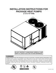
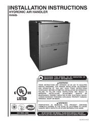
INSTALLATION INSTRUCTIONS<br />
FOR CASED/UNCASED COILS FOR GAS AND OIL<br />
FURNACES:<br />
(-)CFA: featuring R-407C/R-22 Refrigerant<br />
(-)CFL: featuring Industry Standard R-410A Refrigerant<br />
▲WARNING<br />
!<br />
These instructions are intended as an aid to qualified licensed<br />
service personnel for proper installation, adjustment and<br />
operation of this unit. Read these instructions thoroughly before<br />
attempting installation or operation. Failure to follow these<br />
instructions may result in improper installation, adjustment,<br />
service or maintenance possibly resulting in fire, electrical<br />
shock, property damage, personal injury or death.<br />
ISO 9001:2008<br />
<strong>92</strong>-<strong>100105</strong>-<strong>06</strong>-<strong>06</strong><br />
SUPERSEDES <strong>92</strong>-<strong>100105</strong>-<strong>06</strong>-05
TABLE OF CONTENTS<br />
1.0 Safety Information . . . . . . . . . . . . . . . . . . . . . . . . . . . . . . . . . . . . . . . . . . . . . . . . . .3<br />
2.0 General Information . . . . . . . . . . . . . . . . . . . . . . . . . . . . . . . . . . . . . . . . . . . . . . . . .4<br />
2.1 Inspection . . . . . . . . . . . . . . . . . . . . . . . . . . . . . . . . . . . . . . . . . . . . . . . . . . . . . .4<br />
2.2 Codes & Regulations . . . . . . . . . . . . . . . . . . . . . . . . . . . . . . . . . . . . . . . . . . . . .4<br />
2.3 Replacement Parts . . . . . . . . . . . . . . . . . . . . . . . . . . . . . . . . . . . . . . . . . . . . . . .5<br />
2.4 Model Number Explanation . . . . . . . . . . . . . . . . . . . . . . . . . . . . . . . . . . . . . . . .5<br />
2.5 Coil Specifications . . . . . . . . . . . . . . . . . . . . . . . . . . . . . . . . . . . . . . . . . . . . . . .6<br />
2.5A Coil Specifications: Dimensions & Weights . . . . . . . . . . . . . . . . . . . . . . . .6<br />
2.5B Coil Specifications: Airflow Pressure Drop . . . . . . . . . . . . . . . . . . . . . . . .7<br />
3.0 Installation . . . . . . . . . . . . . . . . . . . . . . . . . . . . . . . . . . . . . . . . . . . . . . . . . . . . . . . .7<br />
3.1 Applications . . . . . . . . . . . . . . . . . . . . . . . . . . . . . . . . . . . . . . . . . . . . . . . . . . . .7<br />
3.2 Refrigerant Connections . . . . . . . . . . . . . . . . . . . . . . . . . . . . . . . . . . . . . . . . . .9<br />
3.3 TXV Sensing Bulb . . . . . . . . . . . . . . . . . . . . . . . . . . . . . . . . . . . . . . . . . . . . . . .9<br />
3.4 Condensate Drain Tubing . . . . . . . . . . . . . . . . . . . . . . . . . . . . . . . . . . . . . . . . .9<br />
3.5 Duct Flanges . . . . . . . . . . . . . . . . . . . . . . . . . . . . . . . . . . . . . . . . . . . . . . . . . .10<br />
4.0 Maintenance . . . . . . . . . . . . . . . . . . . . . . . . . . . . . . . . . . . . . . . . . . . . . . . . . . . . . .11<br />
4.1 Air Filter . . . . . . . . . . . . . . . . . . . . . . . . . . . . . . . . . . . . . . . . . . . . . . . . . . . . . .11<br />
4.2 Indoor Coil - Drain Pan - Drain Line . . . . . . . . . . . . . . . . . . . . . . . . . . . . . . . . .11<br />
5.0 Accessories . . . . . . . . . . . . . . . . . . . . . . . . . . . . . . . . . . . . . . . . . . . . . . . . . . . . . .12<br />
5.1 Plenum Adapter Accessory . . . . . . . . . . . . . . . . . . . . . . . . . . . . . . . . . . . . . . .12<br />
5.2 Horizontal Flow Accessory . . . . . . . . . . . . . . . . . . . . . . . . . . . . . . . . . . . . . . . .12<br />
5.3 RXBC- Indoor Coil Casing . . . . . . . . . . . . . . . . . . . . . . . . . . . . . . . . . . . . . . . .13<br />
5.4 Uncased Coil Adapter Kit . . . . . . . . . . . . . . . . . . . . . . . . . . . . . . . . . . . . . . . . .14<br />
2
1.0 SAFETY INFORMATION<br />
! WARNING<br />
These instructions are intended as an aid to qualified licensed service personnel<br />
for proper installation, adjustment and operation of this unit. Read these<br />
instructions thoroughly before attempting installation or operation. Failure to<br />
follow these instructions may result in improper installation, adjustment, service<br />
or maintenance possibly resulting in fire, electrical shock, property damage,<br />
personal injury or death.<br />
! WARNING<br />
PROPOSITION 65: This appliance contains fiberglass insulation. Respirable<br />
particles of fiberglass are known to the State of California to cause cancer.<br />
All manufacturer products meet current Federal OSHA Guidelines for safety.<br />
California Proposition 65 warnings are required for certain products, which are<br />
not covered by the OSHA standards.<br />
California's Proposition 65 requires warnings for products sold in California<br />
that contain or produce any of over 600 listed chemicals known to the State of<br />
California to cause cancer or birth defects such as fiberglass insulation, lead in<br />
brass, and combustion products from natural gas.<br />
All “new equipment” shipped for sale in California will have labels stating that<br />
the product contains and/or produces Proposition 65 chemicals. Although we<br />
have not changed our processes, having the same label on all our products<br />
facilitates manufacturing and shipping. We cannot always know “when, or if”<br />
products will be sold in the California market.<br />
You may receive inquiries from customers about chemicals found in, or produced<br />
by, some of our heating and air-conditioning equipment, or found in natural<br />
gas used with some of our products. Listed below are those chemicals<br />
and substances commonly associated with similar equipment in our industry<br />
and other manufacturers.<br />
• Glass Wool (Fiberglass) Insulation<br />
• Carbon Monoxide (CO).<br />
• Formaldehyde<br />
• Benzene<br />
More details are available at the websites for OSHA (Occupational Safety and<br />
Health Administration), at www.osha.gov and the State of California’s OEHHA<br />
(Office of Environmental Health Hazard Assessment), at www.oehha.org.<br />
Consumer education is important since the chemicals and substances on the<br />
list are found in our daily lives. Most consumers are aware that products present<br />
safety and health risks, when improperly used, handled and maintained.<br />
CAUTION<br />
For horizontal applications, the horizontal drain pan must be located under the<br />
indoor coil. Failure to place the pan under the coil can result in property damage.<br />
CAUTION<br />
It is recommended that an auxiliary/secondary drain pan be installed under units<br />
containing evaporator coils that are located in any area of a structure where<br />
damage to the building or building contents may occur as a result of an overflow<br />
of the coil drain pan or a stoppage in the primary condensate drain piping.<br />
3
2.0. GENERAL INFORMATION<br />
2.1. INSPECTION<br />
Immediately upon receipt, all cartons, and contents should be inspected for transit damage.<br />
Units with damaged cartons should be opened immediately. If damage is found, it<br />
should be noted on the delivery papers and a damage claim filed with the last carrier.<br />
Shipping damage is not covered by the warranty.<br />
• After unit has been delivered to job site, remove carton taking care not to damage<br />
unit.<br />
• Check the unit rating plate to be sure equipment matches what is required for the job<br />
specification.<br />
• Read the entire instructions before starting the installation. This is particularly important<br />
if this is the first installation for this specific model series.<br />
• Many installation steps done prior to installing the unit can save time and simplify the<br />
installation.<br />
2.2. CODES/REGULATIONS<br />
Units should be installed in accordance with any local or national codes which may<br />
apply. Latest editions are available from: “National Fire Protection Association, Inc.,<br />
Batterymarch Park, Quincy, MA 02269.”<br />
These publications are:<br />
• ANSI/NFPA Latest Edition (NEC) National Electrical<br />
Code.<br />
• NFPA90A Installation of Air conditioning and<br />
Ventilating Systems.<br />
• NFPA90B Installation of Warm Air Heating and Air<br />
Conditioning Systems.<br />
4
2.3. REPLACEMENT PARTS<br />
Any replacement part must be the same as or an approved alternate to the original part<br />
supplied. The manufacturer will not be responsible for replacement parts not designed to<br />
physically fit or operate within the design parameters the original parts were selected for.<br />
When ordering replacement parts, it is necessary to order by part number and include<br />
the complete model number and serial number from the coil rating plate. (See parts list<br />
for unit component part numbers. Parts are available through the local distributor.)<br />
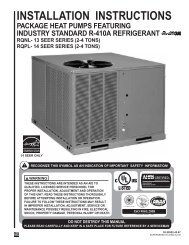
2.4 MODEL NUMBER EXPLANATION<br />
FIGURE 1<br />
MODEL NUMBER EXPLANATION<br />
(-) C F L — HM 24 14 A C<br />
GAS/OIL FURNACE COIL<br />
C = CASED<br />
U = UNCASED<br />
DESIGN VARIATION<br />
A = 1 ST DESIGN<br />
B = 2 ND DESIGN<br />
C = 3 RD DESIGN<br />
COIL SIZE (APPROXIMATE WIDTH)<br />
14 = 14"<br />
17 = 17.5"<br />
21 = 21"<br />
24 = 24.5"<br />
NOMINAL CAPACITY<br />
24/26 = 18,000 TO 24,000 BTU/HR<br />
36/38 = 30,000 TO 36,000 BTU/HR<br />
36/48 = 42,000 TO 48,000 BTU/HR<br />
36/60 = 60,000 BTU/HR<br />
F = PRODUCT GENERATION<br />
CLASSIFICATION<br />
C = COIL<br />
TRADE BRAND<br />
CASED COIL AIRFLOW:<br />
HM = A/C OR HEAT PUMP, MULTI-POSITION<br />
AU = A/C ONLY, UPFLOW / DOWNFLOW<br />
UNCASED COIL AIRFLOW:<br />
HU = A/C OR HEAT PUMP, UPFLOW / DOWNFLOW<br />
REFRIGERANT<br />
A = R-407C/R-22<br />
L = R-410A<br />
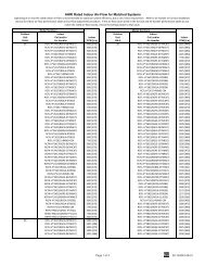
AVAILABLE MODELS OF<br />
RCFA COILS<br />
RCFA-HM2414AC<br />
RCFA-HM2417AC<br />
RCFA-HM3617AC<br />
RCFA-HM3621AC<br />
RCFA-HM4821AC<br />
RCFA-HM4824AC<br />
RCFA-HM6024AC<br />
RCFA-AU2414BC<br />
RCFA-AU2417BC<br />
RCFA-AU3617BC<br />
RCFA-AU3621BC<br />
RCFA-AU4821BC<br />
RCFA-AU4824BC<br />
RCFA-AU6024BC<br />
RCFA-HU2414AU<br />
RCFA-HU2417AU<br />
RCFA-HU3617AU<br />
RCFA-HU3621AU<br />
RCFA-HU4821AU<br />
RCFA-HU4824AU<br />
RCFA-HU6024AU<br />
AVAILABLE MODELS OF<br />
RCFL COILS<br />
RCFL-HM2414CC<br />
RCFL-HU2414CU<br />
RCFL-HM2417CC<br />
RCFL-HU2417CU<br />
RCFL-HM2617CC<br />
RCFL-HU2617CU<br />
RCFL-HM2621CC<br />
RCFL-HU2621CU<br />
RCFL-HM3617CC<br />
RCFL-HU3617CU<br />
RCFL-HM3621CC<br />
RCFL-HU3621CU<br />
RCFL-HM3821CC<br />
RCFL-HU3821CU<br />
RCFL-HM3824CC<br />
RCFL-HU3824CU<br />
RCFL-HM4821CC<br />
RCFL-HU4821CU<br />
RCFL-HM4824CC<br />
RCFL-HU4824CU<br />
RCFL-HM6024CC<br />
RCFL-HU6024CU<br />
5
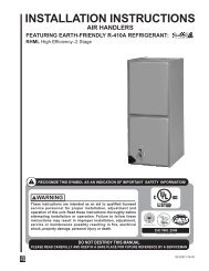
2.5 COIL SPECIFICATIONS<br />
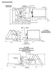
2.5A Coil Specifications: Dimensions & Weights (See Figure 2)<br />
FIGURE 2<br />
DIMENSIONS & WEIGHTS<br />
FRONT VIEW<br />
19 7 /8”<br />
[505 mm]<br />
A MINUS ONE INCH ➀<br />
SECONDARY DRAIN<br />
3/4" N.P.T. (HORIZONTAL)<br />
7 /16”<br />
[11.1 mm]<br />
PLENUM WIDTH<br />
1 13 /16”<br />
5 3 /8”<br />
[46 mm]<br />
[136.5<br />
mm] 2 1 /4”<br />
[57.1 mm]<br />
PRIMARY DRAIN<br />
3/4" N.P.T. (VERTICAL<br />
AND HORIZONTAL)<br />
PRIMARY DRAIN<br />
3/4" N.P.T. (VERTICAL)<br />
1 1 /4”<br />
[31.7 mm]<br />
SECONDARY DRAIN<br />
3/4" N.P.T. (VERTICAL)<br />
NOTE: FLANGES ARE PROVIDED<br />
FOR FIELD INSTALLATION<br />
1 /2"<br />
1 7 /16”<br />
[36.5 mm]<br />
SUCTION LINE<br />
LIQUID LINE<br />
SIDE VIEW<br />
5 15 /16”<br />
[150.8 mm] 4 1 /8”<br />
[104.7 mm]<br />
➀ CASING TOP AND BOTTOM OPENINGS<br />
ARE THE SAME DIMENSIONS.<br />
DIMENSIONS AND WEIGHTS DATA<br />
21 11 /16”<br />
[550.8 mm]<br />
Coil<br />
Model<br />
Liquid<br />
Connections I.D.<br />
Sweat (in) [mm]<br />
Suction<br />
Cased Coil Dimensions (in.) [mm]<br />
A B C<br />
Coil Weight<br />
(lbs.) [Kg]<br />
Weight<br />
Shipping Weight<br />
(lbs.) [Kg]<br />
2414* 3/8 [9.53] 3/4 [19.05] 14 [356] 21 [533] 23 3 /16 [589] 46 [21] 50 [23]<br />
2417 3/8 [9.53] 3/4 [19.05] 17 1 /2 [445] 14 1 /2 [368] 20 [508] 46 [21] 51 [23]<br />
2617/3617 3/8 [9.53] 3/4 [19.05] 17 1 /2 [445] 17 7 /8 [454] 20 [508] 52 [24] 57 [26]<br />
2621/3621 3/8 [9.53] 3/4 [19.05] 21 [533] 17 1 /2 [445] 20 [508] 54 [24] 60 [27]<br />
3821/4821 3/8 [9.53] 7/8 [22.23] 21 [533] 25 7 /8 [657] 28 [711] 76 [34] 83 [38]<br />
3824/4824 3/8 [9.53] 7/8 [22.23] 24 1 /2 [622] 25 3 /8 [645] 32 [812] 89 [40] 99 [45]<br />
6024 3/8 [9.53] 7/8 [22.23] 24 1 /2 [622] 30 1 /4 [768] 32 [812] 108 [49] 118 [54]<br />
*The 14 inch, 2 ton (-)CFA/(-)CFL Coil (2414) is part of the “N” Design Series, even though the coil shape resembles an “A” design.<br />
6
2.5B Coil Specifications: Airflow Pressure Drop<br />
TABLE 1<br />
AIRFLOW PRESSURE DROP<br />
Coil<br />
Model<br />
Approx.<br />
Design<br />
Air Flow<br />
CFM [L/s]<br />
Range<br />
Face<br />
Area<br />
Sq. Ft.<br />
[m 2 ]<br />
Fins-in./<br />
Rows<br />
Deep 600<br />
[283]<br />
700<br />
[330]<br />
800<br />
[378]<br />
900<br />
[425]<br />
Static Pressure Drop Through Wet Cooling Coil [kPa]<br />
(Inches W.C.) CFM [L/s]<br />
HIGH EFFICIENCY COOLING COILS<br />
2414<br />
600/1000 4.56<br />
.17 .21 .25 .31 .40 .46<br />
[283/472] (0.42)<br />
16/2<br />
[.043] [.053] [.<strong>06</strong>3] [.080] [.100] [.117]<br />
— — — — — — — —<br />
2417<br />
600/1000 4.56<br />
.15 .19 .23 .30 .38 .45<br />
[283/472] [0.42]<br />
16/2<br />
[.039] [.049] [.059] [.076] [.096] [.113]<br />
— — — — — — — —<br />
2617/3617<br />
900/1400 5.70<br />
.17 .21 .26 .31 .36 .41<br />
16/2 — —<br />
[424/661] [0.53] [.043] [.053] [.<strong>06</strong>4] [.080] [.0<strong>92</strong>] [.103]<br />
— — — — — —<br />
2621/3621<br />
900/1400 5.70<br />
.15 .18 .23 .27 .31 .37<br />
16/2 — —<br />
[424/661] [0.53] [.038] [.047] [.058] [.<strong>06</strong>9] [.080] [.094]<br />
— — — — — —<br />
3821/4821<br />
1200/1800 8.55<br />
.22 .25 .28 .32 .36 .41<br />
16/2 — — — — — —<br />
[566/850] [0.79] [.056] [.<strong>06</strong>3] [.071] [.081] [.0<strong>92</strong>] [.103]<br />
— —<br />
3824/4824<br />
1200/1800 8.55<br />
.22 .25 .28 .32 .32 .41<br />
16/2 — — — — — —<br />
[566/850] [0.79] [.056] [.<strong>06</strong>3] [.071] [.081] [.081] [.103]<br />
— —<br />
6024<br />
1600/1900 9.98<br />
.27 .30 .34 .37<br />
14/3 — — — — — — — — — —<br />
[755/897] [0.93] [.070] [.076] [.084] [.094]<br />
NOTE: Represents Coil-Only Airflow Ratings.<br />
[ ] Designates Metric Conversion<br />
1000<br />
[472]<br />
1100<br />
[519]<br />
1200<br />
[566]<br />
1300<br />
[614]<br />
1400<br />
[661]<br />
1500<br />
[708]<br />
1600<br />
[755]<br />
1700<br />
[802]<br />
1800<br />
[850]<br />
1900<br />
[897]<br />
TABLE 2<br />
COIL APPLICATION<br />
3.0 INSTALLATION<br />
3.1 APPLICATIONS<br />
(-)CFA-HM and (-)CFL-HM coils can be applied in upflow, downflow, horizontal right and<br />
horizontal left applications without modifications. (-)CFA-AU, (-)CFA-HU, (-)CFL-AU and<br />
(-)CFL-HU coils can only be applied in upflow and downflow applications (See Table 2<br />
and Figure 3). For horizontal applications, installation of a horizontal drip shield is<br />
required. (See Section 5.2: Horizontal Adapter Kit.)<br />
Coil Model<br />
2414, 2417, 3617<br />
2417<br />
2617, 3617<br />
2621, 3621<br />
3821, 4821<br />
3824, 4824<br />
6024<br />
Furnace Width<br />
(In.) [mm]<br />
Oil<br />
Gas<br />
— 14 [356]<br />
21 [533]<br />
17 1 ⁄2 [444]<br />
14 [356]<br />
21 [533]<br />
21 [533]<br />
17 1 ⁄2 [444]<br />
24 1 ⁄2 [622]<br />
24 1 ⁄2 [622]<br />
21 [533]<br />
NOTE: Due to the proximity of the drain pan to the high temperature oil furnace drum, a horizontal left application is not permitted on<br />
all oil furnaces.<br />
CAUTION<br />
For horizontal applications, the horizontal drain pan must be located under the<br />
indoor coil. Failure to place the pan under the coil can result in property damage.<br />
For coils that are two sizes larger than the furnace, for example, a 21” wide coil on a 14”<br />
furnace, a tapered adaptor with a minimum height of 6” is required to evenly distribute<br />
airflow. See Figure 4. For coils that are one size larger than the furnace; for example a<br />
21” wide coil on a 17 1 ⁄2” furnace, seal the gap between the two units with sheet metal, or<br />
use the specified adapter kit (RXBA-AC or RXBA-AD). See Figure 5.<br />
7
FIGURE 3<br />
COIL INSTALLATION OPTIONS<br />
AIRFLOW<br />
PRESSURE<br />
SENSITIVE<br />
GASKET<br />
AIRFLOW<br />
HORIZONTAL LEFT<br />
HORIZONTAL RIGHT<br />
DOWNFLOW<br />
AIRFLOW<br />
AIRFLOW<br />
UPFLOW<br />
IMPORTANT: Coil must be installed on the<br />
supply airflow side of a gas or oil furnace.<br />
FIGURE 4<br />
INSTALLATION OF COIL MATCHED WITH A FURNACE TWO SIZES SMALLER<br />
6.000<br />
MINIMUM<br />
8
FIGURE 5<br />
INSTALLATION OF COIL MATCHED WITH<br />
A FURNACE OF SMALLER SIZE<br />
DOWNFLOW OR<br />
HORIZONTAL<br />
RIGHT APPLICATION<br />
PLENUM<br />
ADAPTER<br />
RXBA-AC or<br />
RXBA-AD<br />
UPFLOW OR HORIZONTAL<br />
LEFT APPLICATION<br />
When a cooling coil is matched with a gas furnace<br />
of one smaller size, always center coil<br />
over the furnace.<br />
IMPORTANT: Seal the gap between the two<br />
units with appropriate sheet metal parts, or use<br />
the adapter kit RXBA-AC (Upflow/Horizontal<br />
80% Furnaces) or RXBA-AD (Downflow/<br />
Horizontal 90 Plus Furnaces).<br />
3.2 REFRIGERANT CONNECTIONS<br />
Keep the coil connections sealed until refrigerant connections are to be made. See the<br />
Installation Instructions for the outdoor unit for details on line sizing, tubing installation,<br />
and charging information.<br />
Coil is shipped with a low (5 - 10 PSIG) pressure charge of dry nitrogen. Evacuate the<br />
system before charging with refrigerant.<br />
Install refrigerant tubing so that it does not block service access to the front of the unit.<br />
Nitrogen should flow through the refrigerant lines while brazing.<br />
Use a brazing shield to protect the cabinet’s paint from being damaged by torch flames.<br />
After the refrigerant connections are made, seal the gap around the connections with<br />
pressure sensitive gasket. If necessary, cut the gasket into two pieces for a better seal<br />
(See Figure 3.)<br />
3.3 TXV SENSING BULB<br />
IMPORTANT: DO NOT perform any soldering with the TXV bulb attached to any line.<br />
After soldering operations have been completed, clamp the TXV bulb securely on the suction<br />
line at the 10 to 2 o’clock position with the strap provided in the parts bag.<br />
Insulate the TXV sensing bulb and suction line with the provided pressure sensitive insulation<br />
(size 4” x 7”) and secure with provided wire ties.<br />
IMPORTANT: TXV sensing bulb should be located on a horizontal section of suction line, just<br />
outside of coil box.<br />
3.4 CONDENSATE DRAIN TUBING<br />
Consult local codes or ordinances for specific requirements.<br />
IMPORTANT: When making drain fitting connections to the drain pan, use a thin layer of Teflon<br />
paste, silicone or Teflon tape and install hand tight.<br />
IMPORTANT: When making drain fitting connections to drain pan, do not overtighten.<br />
Overtightening fittings can split pipe connetions on the drain pan.<br />
9
• Install drain lines so they do not block service access to front of the unit. Minimum<br />
clearance of 24 inches is required for filter, coil or blower removal and service access.<br />
• Make sure unit is level or pitched slightly toward primary drain connection so that<br />
water will drain completely from the pan. (See Figure 6.)<br />
• Do not reduce drain line size less than connection size provided on condensate drain pan.<br />
• All drain lines must be pitched downward away from the unit a minimum of 1/8” per foot of<br />
line to ensure proper drainage.<br />
• Do not connect condensate drain line to a closed or open sewer pipe. Run condensate to an<br />
open drain or outdoors.<br />
• The drain line should be insulated where necessary to prevent sweating and damage due to<br />
condensate forming on the outside surface of the line.<br />
• Make provisions for disconnecting and cleaning of the primary drain line should it become<br />
necessary. Install a 3 in. trap in the primary drain line as close to the unit as possible. Make<br />
sure that the top of the trap is below connection to the drain pan to allow complete drainage<br />
of pan (See Figure 6).<br />
FIGURE 6<br />
CONDENSATE DRAIN TRAP<br />
DO NOT OPERATE UNIT WITHOUT<br />
CONDENSATE DRAIN TRAP.<br />
UNIT<br />
3''<br />
3''<br />
DO NOT OVERTIGHTEN DRAIN FITTING<br />
UNIT MUST BE SLIGHTLY INCLINED<br />
TOWARD DRAIN CONNECTION.<br />
• Auxiliary drain line should be run to a place where it will be noticeable if it becomes operational.<br />
Occupant should be warned that a problem exists if water should begin running from<br />
the auxiliary drain line.<br />
• Plug the unused drain connection with the plugs provided in the parts bag, using a thin layer<br />
of teflon paste, silicone or teflon tape to form a water tight seal.<br />
• Test condensate drain pan and drain line after installation is complete. Pour water into<br />
drain pan, enough to fill drain trap and line. Check to make sure drain pan is draining<br />
completely, no leaks are found in drain line fittings, and water is draining from the termination<br />
of the primary drain line.<br />
3.5 DUCT FLANGES<br />
Field-installed duct flanges (4 pieces) are shipped with units. Install duct flanges as<br />
needed on top or bottom of the coil casing. (See Figure 7.)<br />
CAUTION<br />
It is recommended that an auxiliary/secondary drain pan be installed under units<br />
containing evaporator coils that are located in any area of a structure where<br />
damage to the building or building contents may occur as a result of an overflow<br />
of the coil drain pan or a stoppage in the primary condensate drain piping.<br />
10
4.0 MAINTENANCE<br />
! WARNING<br />
These instructions are intended as an aid to qualified licensed service personnel<br />
for proper installation, adjustment and operation of this unit. Read these<br />
instructions thoroughly before attempting installation or operation. Failure to<br />
follow these instructions may result in improper installation, adjustment,<br />
service or maintenance possibly resulting in fire, electrical shock, property<br />
damage, personal injury or death.<br />
For continuing high performance and to minimize possible equipment failure, it is essential<br />
that annual maintenance be performed on this equipment. Consult your local dealer<br />
as to the availability of a maintenance contract.<br />
4.1 AIR FILTER<br />
Check the system filter every ninety days or as often as found to be necessary and if<br />
obstructed, clean or replace at once.<br />
IMPORTANT: Do not operate the system without a filter in place.<br />
4.2 INDOOR COIL - DRAIN PAN - DRAIN LINE<br />
Inspect the indoor coil once each year for cleanliness and clean as necessary. In some<br />
cases, it may be necessary to remove the filter and check the return side of the coil with<br />
a mirror and flashlight.<br />
IMPORTANT: Do not use caustic household drain cleaners or bleach in the condensate<br />
pan or near the indoor coil. Drain cleaners will quickly damage the indoor coil.<br />
FIGURE 7<br />
UNIVERSAL DUCT FLANGE<br />
11
5.0 ACCESSORIES<br />
5.1 PLENUM ADAPTER ACCESSORIES<br />
NOTE: In a plenum installation on an unknown manufacturer’s furnace, there must be a<br />
minimum of 6” clearance from the top of the furnace to avoid limit-tripping.<br />
RXBA-AE<br />
This plenum adapter accessory is for use with the 24-1/2” wide cased indoor cooling and<br />
heat pump coils. This allows a 24-1/2 wide cased coil to be installed on a 28” wide oil<br />
furnace. This is a field-installed accessory only.<br />
RXBA-AC (Upflow/Horizontal 80% Furnaces)<br />
RXBA-AD (Downflow/Horizontal 90 Plus Furnaces)<br />
This plenum adapter accessory is for installation on cased indoor cooling and heat pump<br />
coils. This allows a nominal size cased coil to be installed on the next smaller size gas or<br />
oil furnace. NOTE: This accessory is for installation on coil casings to fit gas or oil<br />
furnaces only - this accessory must not be used on electric furnaces or heat pump<br />
air handlers. Consult the installation instructions packaged with the accessory for proper<br />
installation.<br />
5.2 HORIZONTAL ADAPTER KIT<br />
RXHH- (See Figure 8)<br />
This horizontal adapter kit is used to convert an upflow or downflow coil for a horizontal<br />
application. See Table 3 to order the proper horizontal adapter kit.<br />
NOTE: The horizontal adapter kit cannot be used for RCFA/RCFL-AU****BC applications.<br />
It can only be used for RCFA/RCFL-HU****AC and for RCFA/RCFL-AU****AC<br />
applications.<br />
FIGURE 8<br />
HORIZONTAL ADAPTER KIT ILLUSTRATION<br />
AIRFLOW:<br />
HORIZONTAL-<br />
DUAL<br />
DIRECTION<br />
HORIZONTAL ADAPTER KIT (RXHH-)<br />
12
TABLE 3<br />
HORIZONTAL ADAPTER KIT<br />
Coil Model<br />
Horizontal Adapter<br />
Kit Model No.<br />
2414 RXHH-A01<br />
2417 RXHH-A02<br />
2617/2621/3617/3621 RXHH-A03<br />
3821/3824/4821/4824 RXHH-A04<br />
6024 RXHH-A05<br />
5.3 INDOOR COIL CASING RXBC - (See Figure 9 & Table 4)<br />
FIGURE 9<br />
MODEL NUMBER EXPLANATION<br />
R X B C — D 14 I<br />
INSULATION<br />
I = Insulated<br />
Blank = Uninsulated<br />
CABINET WIDTH<br />
14 = 14” [355.6 mm]<br />
17 = 17.5” [444.6 mm]<br />
21 = 21” [533.4 mm]<br />
24 = 24.5” [622.3 mm]<br />
DESIGN SERIES<br />
COIL CASING<br />
BLOWER UNIT<br />
ACCESSORY<br />
TRADEBRAND<br />
TABLE 4<br />
UNIT DIMENSIONS & WEIGHTS — RXBC- INDOOR COIL CASINGS<br />
Indoor Coil<br />
Casing Model<br />
Number<br />
Width<br />
In.<br />
Height<br />
In.<br />
Depth<br />
Weight Shipping Weight<br />
In. Lbs [Kg] Lbs [Kg]<br />
RXBC-D14AI 14 23 3 ⁄16 19 [9] 23 [10] 13<br />
RXBC-D17AI 17 1 ⁄2 20 18 [8] 23 [10] 16 1 ⁄2<br />
RXBC-D21AI 21 20 21-5/8 20 [9] 26 [12] 20 19 31 ⁄32<br />
RXBC-D21BI 21 28 27 [12] 36 [17] 20<br />
Width<br />
In.<br />
RXBC-D24AI 24 1 ⁄2 32 1 ⁄2 34 [16] 44 [20] 23 1 ⁄2<br />
Supply Air/Return Air Openings<br />
Depth<br />
In.<br />
13
5.4 UNCASED COIL ADAPTER KIT<br />
RXBA- (See Figure 10 & 11)<br />
This uncased coil adapter kit is used to adapt the coil to a furnace or ductwork. See<br />
Table 5 to order the proper adapter kit. Each kit contains a quantity a 20 adapters.<br />
FIGURE 10<br />
UNCASED COIL ADAPTER KIT ILLUSTRATION<br />
1.6<br />
7.7<br />
A<br />
20.3<br />
FIGURE 11<br />
UNCASED COIL ADAPTER KIT ASSEMBLED<br />
TABLE 5<br />
UNCASED COIL ADAPTER KIT<br />
Uncased Coil<br />
Adapter<br />
Uncased<br />
Model A Coil<br />
Number<br />
Model<br />
RXBA Width In. RCFA/L<br />
B14x20 13.1 -HUxx14<br />
B17x20 16.6 -HUxx17<br />
B21x20 20.1 -HUxx21<br />
B24x20 23.6 -HUxx24<br />
NOTE: Sliding the coil into the coil rail before attaching coil rack front.<br />
14
16 CM 0810