use of new developments of attitude control sensors - FU Berlin, FB MI
use of new developments of attitude control sensors - FU Berlin, FB MI
use of new developments of attitude control sensors - FU Berlin, FB MI

Create successful ePaper yourself
Turn your PDF publications into a flip-book with our unique Google optimized e-Paper software.
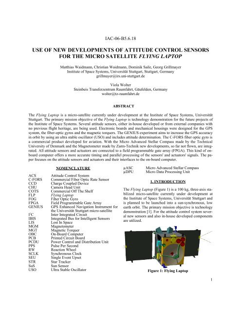
IAC-06-B5.6.18<br />
USE OF NEW DEVELOPMENTS OF ATTITUDE CONTROL SENSORS<br />
FOR THE <strong>MI</strong>CRO SATELLITE FLYING LAPTOP<br />
Matthias Waidmann, Christian Waidmann, Dominik Saile, Georg Grillmayer<br />
Institute <strong>of</strong> Space Systems, Universität Stuttgart, Stuttgart, Germany<br />
grillmayer@irs.uni-stuttgart.de<br />
Viola Wolter<br />
Steinbeis Transferzentrum Raumfahrt, Gäufelden, Germany<br />
wolter@tz-raumfahrt.de<br />
ABSTRACT<br />
The Flying Laptop is a micro-satellite currently under development at the Institute <strong>of</strong> Space Systems, Universität<br />
Stuttgart. The primary mission objective <strong>of</strong> the Flying Laptop is technology demonstration for the future projects <strong>of</strong><br />
the Institute <strong>of</strong> Space Systems. Several <strong>attitude</strong> <strong>sensors</strong>, either in-ho<strong>use</strong> developed or from external companies with<br />
no previous flight heritage, are being <strong>use</strong>d. Electronic boards and mechanical housings were designed for the GPS<br />
system, the fiber-optic gyros and the magnetic torquers. The GENIUS experiment aims to increase the GPS accuracy<br />
in orbit by using an ultra stable oscillator (USO) and includes <strong>attitude</strong> determination. The C-FORS fiber optic gyro is<br />
a commercial product developed for aviation. With the Micro Advanced Stellar Compass made by the Technical<br />
University <strong>of</strong> Denmark and the Magnetometer made by Zarm-Technik <strong>new</strong> <strong>developments</strong>, so far not flown, are integrated.<br />
All <strong>attitude</strong> <strong>sensors</strong> and actuators are connected to a field programmable gate array (FPGA). This kind <strong>of</strong> onboard<br />
computer <strong>of</strong>fers a more accurate timing and parallel processing <strong>of</strong> the <strong>sensors</strong>' and actuators' signals. The paper<br />
foc<strong>use</strong>s on the <strong>attitude</strong> <strong>sensors</strong> and actuators and their interfaces to the on-board computer.<br />
ACS<br />
C-FORS<br />
CCD<br />
CHU<br />
COTS<br />
FLP<br />
FOG<br />
FPGA<br />
GENIUS<br />
I 2 C<br />
IBIS<br />
LIS<br />
MGM<br />
MGT<br />
OBC<br />
PCB<br />
PCDU<br />
PPS<br />
RW<br />
SCLK<br />
SEU<br />
STR<br />
SuS<br />
USO<br />
NOMENCLATURE<br />
Attitude Control System<br />
Commercial Fiber Optic Rate Sensor<br />
Charge Coupled Device<br />
Camera Head Unit<br />
Commercial Off The Shelf<br />
Flying Laptop<br />
Fiber Optic Gyro<br />
Field Programmable Gate Array<br />
GPS Enhanced Navigation Instrument for<br />
the Universität Stuttgart micro-satellite<br />
Inter Integrated Circuit<br />
Integrated Bus for Intelligent Sensors<br />
Lost In Space<br />
Magnetometer<br />
Magnetic Torquer<br />
On-Board Computer<br />
Printed Circuit Board<br />
Power Control and Distribution Unit<br />
Pulse Per Second<br />
Reaction Wheel<br />
Synchronous Clock<br />
Single Event Upset<br />
Star Tracker<br />
Sun Sensor<br />
Ultra Stable Oscillator<br />
µASC<br />
µDPU<br />
Micro Advanced Stellar Compass<br />
Micro Data Processing Unit<br />
1. INTRODUCTION<br />
The Flying Laptop (Figure 1) is a 100 kg, three-axis stabilized<br />
micro-satellite currently under development at<br />
the Institute <strong>of</strong> Space Systems, Universität Stuttgart and<br />
is planned to be launched into a sun-synchronous, low<br />
earth orbit. The primary mission objective is technology<br />
demonstration [1]. For the <strong>attitude</strong> <strong>control</strong> system several<br />
<strong>new</strong> <strong>sensors</strong> and also in-ho<strong>use</strong> developed components<br />
are utilized.<br />
Figure 1: Flying Laptop<br />
1
2. ACS DEVELOPMENT OVERVIEW<br />
The satellite's motion is monitored by five different<br />
types <strong>of</strong> <strong>sensors</strong>: two three-axis magnetometers, two<br />
coarse sun <strong>sensors</strong>, four fiber-optic rate <strong>sensors</strong>, one<br />
autonomous star tracker with two camera heads and<br />
three GPS receivers. The actuators that rotate the satellite<br />
to the desired <strong>attitude</strong> are four reaction wheels and<br />
three magnetic torquers. All <strong>sensors</strong> and actuators are<br />
connected to the FPGA On-Board Computer (OBC) in a<br />
star like configuration. The ACS hardware devices are<br />
shown in Figure 2 and Figure 5, a more detailed description<br />
about the FPGA and the <strong>control</strong> algorithms is given<br />
in [2].<br />
2.1 Operational Modes<br />
The Flying Laptop <strong>use</strong>s different sensor/actuator combinations<br />
for several pointing modes as described in<br />
Table 1:<br />
The objective <strong>of</strong> the detumbling mode is to reduce the<br />
angular velocity after launcher separation. An additional<br />
<strong>use</strong> is rate damping in case <strong>of</strong> accidentally exceeding the<br />
angular velocity limit.<br />
The satellite is commanded to safe mode subsequent to<br />
the initial detumbling phase or in later mission phases<br />
whenever non-recoverable errors occur during pointing<br />
modes. The <strong>sensors</strong> for this mode need to have a high<br />
reliability, sensor outputs need to be available all the<br />
time but only a course pointing knowledge is required.<br />
Thus, only sun sensor and magnetometer information<br />
will be <strong>use</strong>d. The commanded torque is realized with the<br />
help <strong>of</strong> the magnetic torque rods.<br />
Mode<br />
Table 1: Operational Modes<br />
MGT RW MGM SuS STR FOG GPS<br />
Detumbling x x<br />
Safe-Mode x x x<br />
Inertial<br />
Pointing<br />
Nadir<br />
Pointing<br />
Target<br />
Pointing<br />
x x x (x) x x<br />
x x x x x x<br />
x x x x x x<br />
The inertial pointing mode will mainly be <strong>use</strong>d for calibration<br />
and for technology demonstration <strong>of</strong> automated<br />
asteroid detection using the star tracker. A pointing stability<br />
<strong>of</strong> 150 arcseconds is required. Attitude and rate information<br />
is provided by the star tracker and the fiber<br />
optical rate <strong>sensors</strong>. Four reaction wheels are <strong>use</strong>d for<br />
Figure 2: "SpaceCube" for ACS Development<br />
actuation.<br />
During earth observation in nadir pointing mode the<br />
satellite's body axes are aligned with the nadir coordinate<br />
system. The same type <strong>of</strong> non-linear <strong>control</strong>ler with<br />
quaternion and rate feedback as for inertial pointing is<br />
<strong>use</strong>d (the error quaternion now describes the error<br />
between body and nadir frame). The <strong>control</strong>ler allows<br />
for large angle slew maneuvers to a nadir-pointed orientation<br />
from an arbitrary <strong>attitude</strong> and then stabilizes the<br />
satellite's nadir orientation within 150 arcseconds.<br />
No earth referenced <strong>attitude</strong> is directly available from<br />
any sensor, but with the help <strong>of</strong> GPS data it is possible<br />
to transform the initial quaternions from the star tracker<br />
to the nadir frame. First the GPS-time is converted to<br />
JD2000 to calculate the Greenwich Mean Sidereal Time<br />
(GMST). From this, GPS position and velocity can be<br />
transformed from the earth-fixed to the earth-inertial<br />
frame.<br />
In the target pointing mode the satellite remains<br />
aligned towards a fixed point on the earth's surface. This<br />
mode is mainly <strong>use</strong>d for scientific investigations <strong>of</strong> the<br />
bi-directional reflectance distribution function (BRDF),<br />
<strong>of</strong>f-nadir inspection <strong>of</strong> ground areas and during contact<br />
with the ground station using the high gain antennas.<br />
Suitable images for a BRDF target need to be taken<br />
along ±60 ° pitch <strong>of</strong>f nadir and within a maximum roll<br />
angle <strong>of</strong> ±5 °. An image with the payload cameras needs<br />
to be taken at every degree between the ±60 ° during the<br />
flyover.<br />
The <strong>control</strong>ler for this mode is only slightly different<br />
from the one for nadir pointing. It <strong>use</strong>s quaternion and<br />
rate feedback as well but different setpoints for <strong>attitude</strong><br />
and angular velocities. Star tracker, GPS and rate<br />
<strong>sensors</strong> will be <strong>use</strong>d to precisely follow the calculated<br />
<strong>attitude</strong> pr<strong>of</strong>ile within a pointing accuracy <strong>of</strong> 150 arcseconds.<br />
2
2.2 ACS Algorithms<br />
Figure 6 shows a global overview <strong>of</strong> the ACS algorithms.<br />
Each block shown represents a sub-function<br />
with inputs and outputs. On the left, inputs from the 5<br />
<strong>sensors</strong> are shown representing the interface variables<br />
from the lower hardware dependent levels. The Processing<br />
section merges, converts and extrapolates the<br />
sensor variables to the current time and also contains the<br />
Kalman filters. In the Navigation part the reference <strong>attitude</strong><br />
and reference angular velocity are calculated depending<br />
on the pointing mode selected. The Control<br />
section contains the safe mode, detumbling, desaturation,<br />
nullspace, inertial, nadir and target pointing <strong>control</strong>ler<br />
[2]. For the last three an error quarternion feedback<br />
<strong>control</strong>ler is <strong>use</strong>d. The torque output from the <strong>control</strong>lers<br />
is scaled and processed in the Command section<br />
and sent to the wheels and magnetic torquers shown at<br />
the right hand.<br />
2.3 ACS Algorithm Development Process<br />
Figure 3 shows the development cycle for the ACS navigation<br />
and <strong>control</strong> algorithms. After initial theoretical<br />
analysis the algorithms are implemented in Matlab/Simulink<br />
and tested extensively for performance. All functions<br />
which are going to be implemented in the on-board<br />
computer are written as an embedded m-file. In the next<br />
step the algorithms have to be converted to Handel-C,<br />
which is a high level language compiler generating the<br />
binary netlist for the FPGA. Control algorithms and filters<br />
contain a large amount <strong>of</strong> calculations which require<br />
a large amount <strong>of</strong> gates in the FPGA. In order to limit<br />
the space needed on the FPGA almost all variables are<br />
converted to fixed point arithmetic and the outputs <strong>of</strong><br />
the optimized algorithms is compared to the original<br />
double precision algorithms. The comparison is still performed<br />
in the Matlab/Simulink environment and is<br />
identical to the approach <strong>use</strong>d for digital signal processors.<br />
After compilation the netlist is loaded to a prototype<br />
FPGA board (Figure 2) for initial testing. For final<br />
verification <strong>of</strong> the algorithms a real time simulation<br />
environment is needed. A model-based system-simulation<br />
environment represented by the MDVE (Modelbased<br />
Development and Verification Environment) is<br />
<strong>use</strong>d.<br />
3. GENIUS GPS SYSTEM<br />
GPS is a commonly <strong>use</strong>d sensor for satellites in low<br />
earth orbit in order to determine the position and velocity.<br />
This experiment will test the advanced usage <strong>of</strong><br />
GPS for orbit navigation.<br />
GENIUS was developed to serve two purposes. The first<br />
is the standard supply <strong>of</strong> real-time position and velocity<br />
data for on-board usage during nadir and target pointing.<br />
A precision <strong>of</strong> 10 m in position, 0.1 m/s in velocity and<br />
1 µs in time is envisaged using and internal orbit<br />
propagator and the possibility <strong>of</strong> uploading two line elements.<br />
The system is composed <strong>of</strong> three independent receivers,<br />
thus it assures a high level <strong>of</strong> redundancy for<br />
GPS on-board navigation. The second, innovative task<br />
is an experiment conducted in cooperation with the<br />
DLR/GSOC (German Space Operations Center) for accurate<br />
determination <strong>of</strong> the spacecraft <strong>attitude</strong>. This will<br />
be accomplished by the ground analysis <strong>of</strong> the measured<br />
GPS carrier phase <strong>of</strong> each receiver that is recorded on<br />
the satellite and dumped during ground station contacts.<br />
An accuracy <strong>of</strong> 0.1° to 1° is envisaged. Furthermore due<br />
to the <strong>use</strong> <strong>of</strong> an ultra stable time base navigation solutions<br />
with less than 4 tracked satellites can be studied,<br />
considering the future <strong>use</strong> <strong>of</strong> GPS in higher altitude orbits.<br />
3.1 System Design Overview<br />
Each <strong>of</strong> the three Phoenix GPS receivers is connected to<br />
Figure 3: ACS Development Process<br />
Figure 4: GPS Block Diagram<br />
3
Figure 5: Overview <strong>of</strong> ACS Sensors and Actuators<br />
Figure 6: ACS Subfunction Map<br />
4
a separate GPS antenna and low noise amplifier as<br />
shown in Figure 4. The three GPS receivers are integrated<br />
in one box together with an interface board (Figure<br />
7). The three external connections are the on-board<br />
computer, the power <strong>control</strong> and distribution unit<br />
(PCDU) and the ultra-stable-oscillator (USO).<br />
modifications were made to prepare the receiver boards<br />
for space usage and to adjust them to the needs <strong>of</strong> the<br />
GENIUS system. The crystal oscillator <strong>of</strong> the GPS<br />
boards was removed since the time base for the GPS receivers<br />
is provided by an ultra-stable 10 MHz crystal oscillator<br />
(USO) on board the Flying Laptop. This way the<br />
receivers are synchronized for the carrier phase measurements.<br />
Figure 7: GPS Modules<br />
The three antennas are placed on three corners <strong>of</strong> the<br />
satellite in an L-like arrangement, creating two baselines<br />
<strong>of</strong> 44 cm and 61 cm (Figure 8). This configuration is<br />
<strong>use</strong>d to define the spacecraft <strong>attitude</strong>.<br />
Figure 9: GPS Hardware<br />
4. RATE SENSOR<br />
For the measurement <strong>of</strong> the angular rate, the micro-satellite<br />
Flying Laptop is equipped with 4 single-axis COTS<br />
fiber optic rate <strong>sensors</strong> in a tetrahedron configuration.<br />
4.1 Fiber Optic Rate Sensor<br />
Figure 8: GPS Antenna Arrangement on the Solar<br />
Panel.<br />
3.2 Phoenix GPS Receiver<br />
The Phoenix GPS receiver is a commercial GPS receiver<br />
board with a <strong>new</strong> DLR/GSOC developed firmware<br />
for space and high dynamics applications. The receiver<br />
has 12 tracking channels and is able to measure phase<br />
and Doppler shift <strong>of</strong> the GPS-L1 carrier signal. Several<br />
The measurement principle <strong>of</strong> fiber optic rate <strong>sensors</strong> is<br />
based on the Sagnac effect. The <strong>use</strong>d <strong>sensors</strong> C-FORS<br />
(Commercial Fiber Optic Rate Sensor, Figure 10) are<br />
produced for terrestrial and aeronautical applications by<br />
Litef. Due to the <strong>use</strong> <strong>of</strong> COTS parts, the sensor is much<br />
cheaper than space qualified rate <strong>sensors</strong>, but nevertheless<br />
its performance is similar to those <strong>use</strong>d for space<br />
applications. Currently it is one <strong>of</strong> the most accurate rate<br />
<strong>sensors</strong> not subject to ITAR restrictions. By flying the<br />
sensor the space environment effects on the sensor are<br />
evaluated.<br />
The C-FORS [3] is designed to survive shocks <strong>of</strong> up to<br />
250 g (non-operating, 1 ms half-sine) as well as linear<br />
accelerations <strong>of</strong> up to 100 g and sine sweep vibrations<br />
with an amplitude <strong>of</strong> 1.5 g RMS in the frequency range <strong>of</strong><br />
5-2000 Hz. Therefore the sensor is expected to with-<br />
5
Figure 10: Fiber Optic Rate Sensor C-FORS with<br />
Soldered Interface Circuit Board<br />
stand launch without any damage or performance degradation.<br />
Due to the hermetically sealed case <strong>of</strong> the sensor no difference<br />
in the sensor's performance both on ground and<br />
in space is expected. Also outgassing is not an issue.<br />
The operating temperature range <strong>of</strong> -40°C to +75°C is<br />
not expected to be exceeded.<br />
To reduce the total dose ca<strong>use</strong>d by cosmic radiation additional<br />
shielding for the sensor is necessary. Due to the<br />
weight <strong>of</strong> ferromagnetic metals, these cases are made <strong>of</strong><br />
aluminium, no additional shielding against electromagnetic<br />
influences is intended as the sensor already contains<br />
a μ-metal shield around its optic fiber coil. The<br />
wall thickness <strong>of</strong> the shielding is 3 mm.<br />
The C-FORS is configured to measure the angular rate<br />
around its sensitive axis. The output value is the mean<br />
value calculated from the angle increment that is run<br />
through since the last data output, divided by the time<br />
elapsed since the last data output.<br />
The properties and performance <strong>of</strong> the C-FORS according<br />
to the manufacturer's specification and the settings<br />
<strong>use</strong>d for the Flying Laptop are summarized in Table 2.<br />
The performance values <strong>of</strong> the 4 flight models are all<br />
within the specified limits.<br />
Table 2: Characteristics <strong>of</strong> the C-FORS<br />
Mechanical<br />
Dimensions [mm] 78 x 53 x 22<br />
Mass [kg] ≤ 0.13<br />
Environment<br />
Shocks (non-op.)<br />
250g<br />
Linear Accel.<br />
100g<br />
Sine sweep<br />
1.5g RMS (5-2000 Hz)<br />
Temp. Range (op.)<br />
-40°C to +75°C<br />
Performance<br />
Rate Bias [°/h] ≤ 3<br />
Random Walk [°/√h] ≤ 0.15<br />
Scale Factor Error [ppm] ≤ 1000<br />
Magnetic Sensitivity [°/h/mT] 30<br />
Axis misalignment [mrad] ±10 (absolute)<br />
± 1 (stability)<br />
Initialization time [s] ≤ 0.12<br />
Settings<br />
Measurement range [°/s] ±16.771 (max.±1000)<br />
LSB [°/s] 2·10 -6<br />
Resolution [bit] 24<br />
Data rate [Hz] 10 (5 – 4000)<br />
Electrical<br />
Power Consumption [W] < 2.5<br />
The electrical interface for both power supply and communication<br />
is provided via soldering pins. Each sensor<br />
requires three different voltages for power supply according<br />
to Table 3.<br />
Table 3: Power Supply <strong>of</strong> the C-FORS<br />
Nominal voltage [VDC] +5 -5 +3.3<br />
Max. current [mA] 100 40 540<br />
The <strong>use</strong> <strong>of</strong> 4 rate <strong>sensors</strong> in a tetrahedron configuration<br />
requires a mounting platform. Furthermore, an electronic<br />
unit for power supply <strong>of</strong> the <strong>sensors</strong> and for communication<br />
is needed.<br />
4.2 Design Fundamentals<br />
The design is based on single redundancy and the <strong>use</strong> <strong>of</strong><br />
COTS parts which are not specially space qualified.<br />
For the measurement <strong>of</strong> the three angular rates around<br />
the satellite's axes three <strong>sensors</strong> are needed. The designed<br />
FOG-unit <strong>use</strong>s 4 independent <strong>sensors</strong> to allow for<br />
autonomous detection <strong>of</strong> a single failure.<br />
For the whole unit COTS parts are selected, but taking<br />
into account the design requirements for the space environment.<br />
Space qualified micro-D connectors are <strong>use</strong>d to<br />
minimize size.<br />
The whole unit has to fit in a given envelope and be as<br />
compact and light-weight as possible due to the limited<br />
dimensions and weight <strong>of</strong> the micro-satellite.<br />
4.3 Electrical Design<br />
In Figure 11 an overview <strong>of</strong> the electrical configuration<br />
is given. The dashed box comprises the FOG-unit in-<br />
6
Figure 12: Power supply <strong>of</strong> one FOG (data lines and<br />
ground not illustrated).<br />
Figure 11: Electrical Design Overview<br />
cluding the 4 <strong>sensors</strong> and an electronic unit (FOG electronics).<br />
Both, power supply and communication is independent<br />
for each FOG but placed together on this<br />
common electronic board.<br />
A small interface board is soldered to the bottom side <strong>of</strong><br />
each FOG (Figure 10) to provide a connector interface.<br />
The DC/DC converters and the signal driver mainly consist<br />
<strong>of</strong> commercial integrated circuits.<br />
4.4 Power Supply<br />
Due to the necessity <strong>of</strong> 4 independent <strong>sensors</strong>, each <strong>of</strong><br />
the <strong>sensors</strong> is supplied separately by the Power Control<br />
and Distribution Unit (PCDU). To avoid a huge amount<br />
<strong>of</strong> wires and due to the exigency <strong>of</strong> switching all<br />
voltages simultaneously, only one voltage <strong>of</strong> +5.2 V is<br />
supplied 4 times by the PCDU. The operating voltages<br />
for each <strong>of</strong> the <strong>sensors</strong> (Table 3) are generated by<br />
DC/DC converters located on the common electronic<br />
unit as shown for one FOG in Figure 12. Each converter<br />
ensures the required voltage stability <strong>of</strong> all supply<br />
voltages for each FOG and a simultaneous switch on<br />
and <strong>of</strong>f <strong>of</strong> the voltages.<br />
4.5 Data transmission<br />
The C-FORS provides both an asynchronous and a synchronous<br />
interface for communication.<br />
The synchronous interface allows for a maximum data<br />
rate <strong>of</strong> 4 kHz, as opposed to a possible maximum data<br />
rate <strong>of</strong> 1 kHz for the asynchronous interface. Also, the<br />
Figure 13: Data lines between FOG and OBC (power<br />
supply and ground not illustrated)<br />
data request is issued to all four <strong>sensors</strong> at exactly the<br />
same time. Thus the data from each sensor is exactly<br />
synchronized to the OBC time. For this reason the common<br />
synchronous 4-wire IBIS bus is utilized (Figure<br />
13). The SCLK line is <strong>use</strong>d to issue a 2 MHz clock signal<br />
to each sensor. On the receive frame synchronization<br />
(RFS) line, a 500 ns pulse synchronization signal triggers<br />
the simultaneous generation <strong>of</strong> measurement data in<br />
each FOG every 256 clock cycles. The <strong>sensors</strong> are then<br />
read out sequentially following a preprogrammed<br />
scheme.<br />
The IBIS lines <strong>of</strong> the FOGs are connected to the common<br />
bus on the electronic unit, where the ground asymmetric<br />
signals are converted into ground symmetric signals<br />
by a signal driver for transmission to the OBC. If<br />
any FOG is powered down, the sensor is disconnected<br />
from the IBIS by an analog switch. Thus, the bus is not<br />
affected by an defective and/or powered down FOG.<br />
4.6 Heat Dissipation<br />
The waste heat produced by the DC/DC-converters and<br />
the signal driver is dissipated via the mounting screws <strong>of</strong><br />
the printed circuit board <strong>of</strong> the FOG electronics.<br />
7
4.7 Mechanical Design<br />
The whole FOG-unit is shown in Figure 14 and within<br />
the satellite in Figure 15. It consists <strong>of</strong> the following<br />
main parts:<br />
• Electronic box which is both mounting interface to<br />
the satellite and housing <strong>of</strong> the main electronic unit.<br />
• Electronic unit;<br />
• Base plate which is both cover for the electronic<br />
box and basis for the tetrahedron alignment <strong>of</strong> the<br />
FOGs;<br />
• Ramps and a mounting plate for the assembly <strong>of</strong> the<br />
FOGs in tetrahedron configuration;<br />
• FOGs including the interface board equipped with<br />
the interface connector;<br />
• Shielding cases for reduction <strong>of</strong> the total radiation<br />
dose.<br />
The system is currently being assembled. The calculated<br />
total weight is approx. 1.7 kg at the overall dimensions<br />
<strong>of</strong> 186 x 122 x 150 mm (LxWxH).<br />
5. STAR TRACKER<br />
The star tracker is the most accurate <strong>attitude</strong> determination<br />
sensor on the Flying Laptop. The selected model is<br />
the micro-Advanced Stellar Compass (µASC) <strong>of</strong> the<br />
Technical University <strong>of</strong> Denmark.<br />
Figure 16: Micro-Advanced Stellar Compass (left)<br />
and Camera Head Unit & Baffle (right)<br />
The µASC is the successor <strong>of</strong> the Advanced Stellar<br />
Compass, which has been successfully <strong>use</strong>d for more<br />
than 15 missions for ESA, CNES, NASA, DLR and<br />
NASDA. Its smaller size and lighter weight makes it a<br />
suitable device for micro-satellites like the Flying<br />
Laptop. So far it was not launched on a satellite.<br />
The µASC system (Figure 16) consists <strong>of</strong> 3 separate<br />
units; the micro-Data Processing Unit (µDPU), the<br />
Camera Head Unit (CHU) and the baffle system.<br />
In normal operation, the µDPU creates a digital image<br />
<strong>of</strong> the acquired analogue data received from the CHUs<br />
every 0.5 s and stores it in the internal RAM. In further<br />
computing, the lens distortion is removed and the image<br />
is sifted for adequately bright objects. The amount <strong>of</strong><br />
bright objects that are found in an image can be influenced<br />
by varying a s<strong>of</strong>tware parameter, but should never<br />
be below 16 stars, which is the minimum to guarantee<br />
Figure 14: FOG Unit<br />
Figure 15: FOG Unit within the Micro-Satellite<br />
Flying Laptop<br />
Figure 17: Image taken by the CHU with exemplary<br />
position and magnitude <strong>of</strong> three stars<br />
8
eliable information. The developers recommend an<br />
amount <strong>of</strong> detected stars between 20 and 80. Up to 199<br />
stars can be detected. The center and magnitude <strong>of</strong> each<br />
detected star is determined and stored in a list. Figure 17<br />
shows a representative image where the position and<br />
magnitude <strong>of</strong> 3 stars is labeled. In normal operation, the<br />
stars are matched against the star catalog. It contains approximately<br />
the 12,000 brightest stars and is based on<br />
the Hipparcos catalog supplemented by Tycho II. If the<br />
match quality is within a defined threshold, the <strong>new</strong> <strong>attitude</strong><br />
is found. Under the threshold, a further procedure,<br />
the Lost In Space (LIS) mode, is initiated automatically.<br />
In this mode, stars that are brighter than a certain value<br />
and their neighbours are compared to a separate star<br />
database to find a crude <strong>attitude</strong>. This database contains<br />
the <strong>attitude</strong> and distances between the 4,000 brightest<br />
stars and is <strong>use</strong>d either to feed the normal operation algorithm,<br />
the initial <strong>attitude</strong> determination or helps to<br />
provide a coarse <strong>attitude</strong> in case <strong>of</strong> high rotation. The <strong>attitude</strong><br />
is delivered to the OBC as quaternions in the heliocentric<br />
inertial equatorial reference frame J2000.0.<br />
5.1 Camera Head Unit (CHU)<br />
The CHU <strong>use</strong>s a CCD-chip with a size <strong>of</strong><br />
7.95 mm x 6.45 mm with 752 x 558 pixels to make images<br />
<strong>of</strong> the firmament. Stray light <strong>of</strong> bright objects like<br />
the sun, the earth and the moon that could interfere with<br />
the measurement is absorbed in the baffle system, which<br />
also reduces the field <strong>of</strong> view for each CHU to<br />
13.4° x 18.4°.<br />
While the µASC is capable <strong>of</strong> supporting four CHUs,<br />
for the Flying Laptop a configuration <strong>of</strong> two CHUs was<br />
selected as a compromise between <strong>attitude</strong> availability<br />
on the one hand and available space and size (specially<br />
for the baffles) on the other hand.<br />
5.2 Micro-Data Processing Unit (µDPU)<br />
The data acquired by the CHUs is picked up by the<br />
µDPU to process the satellite's <strong>attitude</strong>. It is equipped<br />
with a 486 microprocessor and three types <strong>of</strong> memory; a<br />
Figure 19: Integration <strong>of</strong> the Star Tracker System on<br />
the Flying Laptop<br />
64 kB PROM , an 8 MB Flash and an 8 MB RAM.<br />
5.3 Electrical Interface<br />
As shown in Figure 18 the µDPU is connected to the onboard<br />
computer through a RS-422 interface with<br />
115200 baud. The 20 V power supply is provided by the<br />
power <strong>control</strong> and distribution unit (PCDU). The nominal<br />
power consumption for the FLP configuration with<br />
two CHUs is 5 W. For ground tests, the µDPU can additionally<br />
be <strong>control</strong>led by a PC over a special debug line.<br />
5.4 Arrangement on the Satellite<br />
Figure 19 shows the integration <strong>of</strong> the star-tracker system<br />
on the FLP. Both CHUs with corresponding baffles<br />
are placed on an optical bench and connected with the<br />
µDPU which is located on the other side <strong>of</strong> the bench.<br />
To avoid blinding, an analysis for the angle between the<br />
boresight <strong>of</strong> the CHUs and the sun-earth axis has been<br />
conducted. The orientation <strong>of</strong> the CHUs has to be<br />
chosen in a way that the mentioned angle does not fall<br />
below the worst case sun exclusion angle <strong>of</strong> 55° and the<br />
Figure 18: µASC Interface Diagram<br />
Figure 20: Orientation <strong>of</strong> CHUs and Baffles.<br />
9
earth exclusion angle <strong>of</strong> 25° and that the system still fits<br />
into the already tightly packed satellite design. These<br />
studies have led to the following orientation <strong>of</strong> the<br />
CHUs with respect to the axes <strong>of</strong> the satellite: 125° elevation<br />
from the z-axis and 45° between the two CHUs<br />
(Figure 20). This orientation avoids blinding <strong>of</strong> the<br />
CHUs for most <strong>of</strong> the pointing maneuvers.<br />
The baffles are optimized for earth proximity operations<br />
to maximize roll at the expense <strong>of</strong> the sun exclusion<br />
angle.<br />
5.5 Accuracy<br />
The µASC allows the determination <strong>of</strong> the <strong>attitude</strong> within<br />
an accuracy <strong>of</strong> 1-2 arcseconds for an angular rate <strong>of</strong><br />
less than 0.025°/s [4]. The accuracy is disturbed by various<br />
influences. The most obvious disturbance is ca<strong>use</strong>d<br />
by motion and rotation <strong>of</strong> the satellite that ca<strong>use</strong>s a<br />
smearing <strong>of</strong> some <strong>of</strong> the stars on the image or even moving<br />
them out <strong>of</strong> the FOV. The µASC is much more sensitive<br />
to rotations across the boresight than around it: For<br />
an update rate <strong>of</strong> 0.5 s, the µASC switches to the LIS<br />
mode for a rotation <strong>of</strong> 4°/s around boresight, whereas<br />
this mode is already reached for a rotation <strong>of</strong> 0.4°/s<br />
across boresight. A higher update rate allows higher angular<br />
rates but reduces integration time and thus accuracy.<br />
For highest accuracy 2 Hz update rate is recommended<br />
by the Technical University <strong>of</strong> Denmark.<br />
Furthermore, precession and nutation <strong>of</strong> the earth ca<strong>use</strong><br />
deviations from the true <strong>attitude</strong> beca<strong>use</strong> the output quaternions<br />
are given in an equatorial system, leading to an<br />
error <strong>of</strong> about 5 arcseconds per year. Orbital aberration<br />
and annual aberration results from relativistic effects <strong>of</strong><br />
fast movement <strong>of</strong> the satellite around the earth and the<br />
sun. The maximum displacement ca<strong>use</strong>d by annual aberration<br />
is 5.4 arcseconds in LEO. On the Flying Laptop it<br />
is possible to correct these effects by transmitting the<br />
GPS time and position to the star tracker.<br />
Another error is ca<strong>use</strong>d by the inaccuracy <strong>of</strong> the internal<br />
clock <strong>of</strong> the star tracker. To minimize it, the clock is<br />
synchronized with the ultra-stable on-board computer<br />
clock every 10 seconds.<br />
6. MAGNETOMETER<br />
The satellite is equipped with two 3-axis anisotropicmagneto-resistive<br />
(AMR) magnetometers manufactured<br />
by Zarm-Technik. It is a <strong>new</strong> development that was initiated<br />
by the Flying Laptop project.<br />
The measured vector <strong>of</strong> the earth's magnetic field is <strong>use</strong>d<br />
as input information for the magnetic torquers, for<br />
detumbling after launcher separation, rate damping in<br />
case <strong>of</strong> accidentally exceeding the angular velocity limit<br />
Figure 21: AMR Magnetometer<br />
and desaturation <strong>of</strong> the momentum wheels.<br />
An integrated three-axis AMR sensor HMC-1023 from<br />
Honeywell measures the magnetic field in three directions<br />
[5] . For each direction, an independent permalloy<br />
bridge is <strong>use</strong>d for magnetic measurement. The output is<br />
linear proportional to the applied magnetic field. The<br />
analogue sensor output voltage is converted into a digital<br />
value by a sigma delta A/D-converter. The magnetometer<br />
temperature is monitored by a temperature sensor<br />
that is also <strong>use</strong>d for temperature compensation. A micro<strong>control</strong>ler<br />
handles the communication between <strong>use</strong>r and<br />
<strong>sensors</strong>. The magnetometer is encased by a housing consisting<br />
<strong>of</strong> 2 to 3 mm aluminium alloy.<br />
6.1 Magnetometer Interface<br />
The magnetometer is connected to the on-board computer<br />
by a RS-422 interface with 57 600 baud. A micro-<br />
D connector is <strong>use</strong>d on the magnetometer for communication<br />
and 5 V (0.082 W) power supply.<br />
After each data request a response message, containing<br />
2 bytes <strong>of</strong> data for each direction and additional 2 bytes<br />
for the temperature, is transmitted to the on-board computer.<br />
The magnetometer runs in fast mode using an integration<br />
time <strong>of</strong> 167 ms, but data is requested only<br />
every 5 s when the magnetic torquers are shut <strong>of</strong>f.<br />
The sensor sensitivity is about 8.5 nT. The A/D-converter<br />
resolution is 16 bits, which is equal to 5 nT for the<br />
last significant bit. The measurement range is ±150 µT.<br />
The manufacturer states an accuracy <strong>of</strong> < ± 1%.<br />
7. MAGNETIC TORQUER<br />
Three ZARM-Technik magnetic torquers (torque rods)<br />
with a linear dipole moment <strong>of</strong> 6 Am² are utilized. The<br />
torquers are connected to a power switch that is commanded<br />
by two independent I 2 C b<strong>use</strong>s from the OBC<br />
(Figure 22). The magnetic torquer system is essential to<br />
the satellites functioning and thus the whole system is<br />
10
Figure 22: MGT Block Diagram<br />
Figure 24: OBC Block Diagram<br />
10. ON-BOARD COMPUTER<br />
Figure 23: Magnetic Torquer Power Electronics<br />
fully redundant.<br />
The power electronics contain an H-bridge supplying<br />
the torquers with either 5V, -5V or switched <strong>of</strong>f (bangbang<br />
actuation). The torquers are pulse-width-modulated<br />
and commanded by the acsPWM subroutine in the<br />
ACS <strong>control</strong>ler via the I 2 C interface. Again, to reduce<br />
mass the pockets <strong>of</strong> the aluminium case are milled out as<br />
shown in Figure 23.<br />
8. SUN SENSORS<br />
The sun <strong>sensors</strong> system consists <strong>of</strong> two three-axis<br />
Coarse Sun Sensors from Sun Space mounted at diagonal<br />
corners <strong>of</strong> the satellite. The sensor's voltages are digitized<br />
and sent to the OBC via two I 2 C b<strong>use</strong>s.<br />
9. REACTION WHEELS<br />
Four reaction wheels RSI 01-5/28 made by Teldix are<br />
running in a single hot redundant tetrahedron configuration<br />
with nullspace <strong>control</strong>. Each <strong>of</strong> the wheels has an<br />
angular momentum capacity <strong>of</strong> 0.12 Nms and a reaction<br />
torque <strong>of</strong> 5 mNm over the range <strong>of</strong> ±3000 rpm. The reaction<br />
wheels are connected to the on-board computer<br />
via a RS-422 interface at 9600 baud.<br />
The on-board computer (OBC) <strong>of</strong> the Flying Laptop is a<br />
<strong>new</strong> development based on field programmable gate arrays<br />
(FPGAs). The OBC computer consists <strong>of</strong> four<br />
FPGA nodes (Figure 24), each <strong>of</strong> which can act as the<br />
master OBC. The quadruple redundancy is necessary to<br />
handle radiation as the individual nodes are not radiation<br />
hard. The master OBC is selected by a radiation<br />
hardened command decoder and voter (CDV).<br />
The FPGA OBC nodes are programmed with Handel-C,<br />
a programming language simular to C, developed especially<br />
for FPGAs. Handel-C allows programming in the<br />
high-level-language style with the additional feature <strong>of</strong><br />
direct hardware manipulation.<br />
10.1 Sensor Control by the FPGA<br />
All <strong>sensors</strong> and actuators are connected to the OBC.<br />
Each <strong>of</strong> the four FPGA nodes is able to listen to signals<br />
from the <strong>sensors</strong>. Only the master node is allowed to<br />
send commands. If a restart <strong>of</strong> a node is necessary, e.g.<br />
ca<strong>use</strong>d by a single event upset (SEU), it can synchronize<br />
itself to the other nodes by listening to the signals from<br />
the <strong>sensors</strong> and through synchronization signals between<br />
the nodes.<br />
The <strong>use</strong> <strong>of</strong> FPGAs allows the implementation <strong>of</strong> many<br />
kinds <strong>of</strong> interfaces directly in the FPGA. Asynchronous<br />
as well as synchronous communication is possible, binary<br />
signals like clocks can be issued with only minor<br />
limitations. Since most <strong>of</strong> the <strong>attitude</strong> <strong>control</strong> <strong>sensors</strong><br />
and actuators are designed for the <strong>use</strong> with micro-processor<br />
systems, serial communication is the most common<br />
interface. It is <strong>use</strong>d by the GPS, the reaction wheel,<br />
the magnetometer and the star tracker. For the fiber optic<br />
gyro synchronous serial communication is chosen.<br />
For <strong>sensors</strong> and actuators that require only simple and<br />
low amount <strong>of</strong> data communication, the I 2 C Bus was selected<br />
like for the magnetic torquers and sun <strong>sensors</strong>.<br />
11
10.2 FPGA Advantages<br />
When serial communication is <strong>use</strong>d for the sensor <strong>control</strong>,<br />
the speed is mostly determined by the serial baud<br />
rate and the response time by the <strong>sensors</strong>. With the<br />
FPGA real parallel transmission, reception and processing<br />
<strong>of</strong> the many interfaces is possible.<br />
Another advantage <strong>of</strong> programs running in hardware is<br />
the time stability. When telemetry is received from the<br />
<strong>sensors</strong>, the time for the processing <strong>of</strong> the message is always<br />
exactly the same (no interrupts like for micro-<strong>control</strong>lers)<br />
and can also be pre-calculated as a function <strong>of</strong><br />
the OBC internal clock rate.<br />
The GPS and the star tracker are the only devices that<br />
do not require a data request or command, but send their<br />
telemetry individually and not in sync to the ACS <strong>control</strong><br />
cycle. The GPS therefore sends a PPS synchronization<br />
signal every second. The star tracker on the other is<br />
synchronized directly with a PPS signal every<br />
10 seconds. Having always a constant processing time<br />
directly results in no time variation and thus the best<br />
available navigation accuracy.<br />
[5] Zarm-Technik GmbH, “Magnetometer Manual<br />
(MM)”, IRS-ZAR-MAG-MM-01-0001, Issue 1,<br />
2006.<br />
11. CONCLUSIONS<br />
The <strong>attitude</strong> <strong>control</strong> system contributes to the main purpose<br />
<strong>of</strong> the Flying Laptop, technology demonstration,<br />
by using <strong>new</strong> developed components and COTS<br />
devices. The critical components are redundant as a<br />
safeguard against unpredicted failures. New concepts<br />
like the GENIUS GPS system and the FPGA on-board<br />
computer are <strong>use</strong>d to increase the overall performance<br />
<strong>of</strong> the <strong>attitude</strong> <strong>control</strong> system.<br />
REFERENCES<br />
[1] Grillmayer, G., Falke, A. and Roeser, H.P., “Technology<br />
Demonstration with the Micro-Satellite Flying<br />
Laptop”, Selected Proceedings <strong>of</strong> the 5th IAA<br />
Symposium on Small Satellites for Earth Observation,<br />
<strong>Berlin</strong>, Germany, 4-8 Apr. 2005, pp. 419-427.<br />
[2] Grillmayer, G., Hirth, M., Huber, F., Wolter, V.,<br />
“Development <strong>of</strong> an FPGA Based Attitude Control<br />
System for a Micro-Satellite”, AIAA-2006-6522,<br />
AIAA/AAS Astrodynamics Specialist Conference,<br />
Keystone, CO, USA, 21-24 Aug. 2006.<br />
[3] Litef GmbH, “Specification <strong>of</strong> the Litef C-FORS<br />
fiber-optic gyroscope”, 144410-0000-312, Rev. B,<br />
2005.<br />
[4] Technical University <strong>of</strong> Denmark, “micro-Advanced<br />
Stellar Compass User's Manual”, IRS-DTU-MA-<br />
3001, Issue 1.1, 2005.<br />
12