use of new developments of attitude control sensors - FU Berlin, FB MI
use of new developments of attitude control sensors - FU Berlin, FB MI
use of new developments of attitude control sensors - FU Berlin, FB MI

Create successful ePaper yourself
Turn your PDF publications into a flip-book with our unique Google optimized e-Paper software.
4.7 Mechanical Design<br />
The whole FOG-unit is shown in Figure 14 and within<br />
the satellite in Figure 15. It consists <strong>of</strong> the following<br />
main parts:<br />
• Electronic box which is both mounting interface to<br />
the satellite and housing <strong>of</strong> the main electronic unit.<br />
• Electronic unit;<br />
• Base plate which is both cover for the electronic<br />
box and basis for the tetrahedron alignment <strong>of</strong> the<br />
FOGs;<br />
• Ramps and a mounting plate for the assembly <strong>of</strong> the<br />
FOGs in tetrahedron configuration;<br />
• FOGs including the interface board equipped with<br />
the interface connector;<br />
• Shielding cases for reduction <strong>of</strong> the total radiation<br />
dose.<br />
The system is currently being assembled. The calculated<br />
total weight is approx. 1.7 kg at the overall dimensions<br />
<strong>of</strong> 186 x 122 x 150 mm (LxWxH).<br />
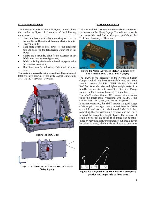
5. STAR TRACKER<br />
The star tracker is the most accurate <strong>attitude</strong> determination<br />
sensor on the Flying Laptop. The selected model is<br />
the micro-Advanced Stellar Compass (µASC) <strong>of</strong> the<br />
Technical University <strong>of</strong> Denmark.<br />
Figure 16: Micro-Advanced Stellar Compass (left)<br />
and Camera Head Unit & Baffle (right)<br />
The µASC is the successor <strong>of</strong> the Advanced Stellar<br />
Compass, which has been successfully <strong>use</strong>d for more<br />
than 15 missions for ESA, CNES, NASA, DLR and<br />
NASDA. Its smaller size and lighter weight makes it a<br />
suitable device for micro-satellites like the Flying<br />
Laptop. So far it was not launched on a satellite.<br />
The µASC system (Figure 16) consists <strong>of</strong> 3 separate<br />
units; the micro-Data Processing Unit (µDPU), the<br />
Camera Head Unit (CHU) and the baffle system.<br />
In normal operation, the µDPU creates a digital image<br />
<strong>of</strong> the acquired analogue data received from the CHUs<br />
every 0.5 s and stores it in the internal RAM. In further<br />
computing, the lens distortion is removed and the image<br />
is sifted for adequately bright objects. The amount <strong>of</strong><br />
bright objects that are found in an image can be influenced<br />
by varying a s<strong>of</strong>tware parameter, but should never<br />
be below 16 stars, which is the minimum to guarantee<br />
Figure 14: FOG Unit<br />
Figure 15: FOG Unit within the Micro-Satellite<br />
Flying Laptop<br />
Figure 17: Image taken by the CHU with exemplary<br />
position and magnitude <strong>of</strong> three stars<br />
8