use of new developments of attitude control sensors - FU Berlin, FB MI
use of new developments of attitude control sensors - FU Berlin, FB MI
use of new developments of attitude control sensors - FU Berlin, FB MI

Create successful ePaper yourself
Turn your PDF publications into a flip-book with our unique Google optimized e-Paper software.
eliable information. The developers recommend an<br />
amount <strong>of</strong> detected stars between 20 and 80. Up to 199<br />
stars can be detected. The center and magnitude <strong>of</strong> each<br />
detected star is determined and stored in a list. Figure 17<br />
shows a representative image where the position and<br />
magnitude <strong>of</strong> 3 stars is labeled. In normal operation, the<br />
stars are matched against the star catalog. It contains approximately<br />
the 12,000 brightest stars and is based on<br />
the Hipparcos catalog supplemented by Tycho II. If the<br />
match quality is within a defined threshold, the <strong>new</strong> <strong>attitude</strong><br />
is found. Under the threshold, a further procedure,<br />
the Lost In Space (LIS) mode, is initiated automatically.<br />
In this mode, stars that are brighter than a certain value<br />
and their neighbours are compared to a separate star<br />
database to find a crude <strong>attitude</strong>. This database contains<br />
the <strong>attitude</strong> and distances between the 4,000 brightest<br />
stars and is <strong>use</strong>d either to feed the normal operation algorithm,<br />
the initial <strong>attitude</strong> determination or helps to<br />
provide a coarse <strong>attitude</strong> in case <strong>of</strong> high rotation. The <strong>attitude</strong><br />
is delivered to the OBC as quaternions in the heliocentric<br />
inertial equatorial reference frame J2000.0.<br />
5.1 Camera Head Unit (CHU)<br />
The CHU <strong>use</strong>s a CCD-chip with a size <strong>of</strong><br />
7.95 mm x 6.45 mm with 752 x 558 pixels to make images<br />
<strong>of</strong> the firmament. Stray light <strong>of</strong> bright objects like<br />
the sun, the earth and the moon that could interfere with<br />
the measurement is absorbed in the baffle system, which<br />
also reduces the field <strong>of</strong> view for each CHU to<br />
13.4° x 18.4°.<br />
While the µASC is capable <strong>of</strong> supporting four CHUs,<br />
for the Flying Laptop a configuration <strong>of</strong> two CHUs was<br />
selected as a compromise between <strong>attitude</strong> availability<br />
on the one hand and available space and size (specially<br />
for the baffles) on the other hand.<br />
5.2 Micro-Data Processing Unit (µDPU)<br />
The data acquired by the CHUs is picked up by the<br />
µDPU to process the satellite's <strong>attitude</strong>. It is equipped<br />
with a 486 microprocessor and three types <strong>of</strong> memory; a<br />
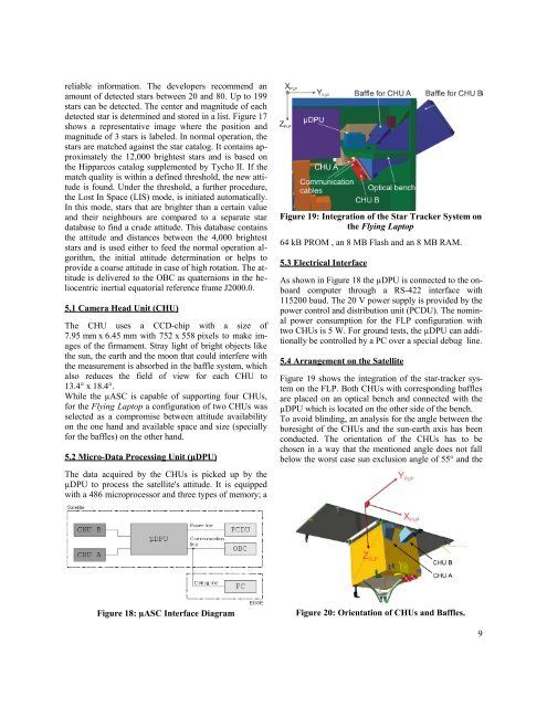
Figure 19: Integration <strong>of</strong> the Star Tracker System on<br />
the Flying Laptop<br />
64 kB PROM , an 8 MB Flash and an 8 MB RAM.<br />
5.3 Electrical Interface<br />
As shown in Figure 18 the µDPU is connected to the onboard<br />
computer through a RS-422 interface with<br />
115200 baud. The 20 V power supply is provided by the<br />
power <strong>control</strong> and distribution unit (PCDU). The nominal<br />
power consumption for the FLP configuration with<br />
two CHUs is 5 W. For ground tests, the µDPU can additionally<br />
be <strong>control</strong>led by a PC over a special debug line.<br />
5.4 Arrangement on the Satellite<br />
Figure 19 shows the integration <strong>of</strong> the star-tracker system<br />
on the FLP. Both CHUs with corresponding baffles<br />
are placed on an optical bench and connected with the<br />
µDPU which is located on the other side <strong>of</strong> the bench.<br />
To avoid blinding, an analysis for the angle between the<br />
boresight <strong>of</strong> the CHUs and the sun-earth axis has been<br />
conducted. The orientation <strong>of</strong> the CHUs has to be<br />
chosen in a way that the mentioned angle does not fall<br />
below the worst case sun exclusion angle <strong>of</strong> 55° and the<br />
Figure 18: µASC Interface Diagram<br />
Figure 20: Orientation <strong>of</strong> CHUs and Baffles.<br />
9