Chemtrol 255 Manual - Texas Aquatic Supply
Chemtrol 255 Manual - Texas Aquatic Supply
Chemtrol 255 Manual - Texas Aquatic Supply

You also want an ePaper? Increase the reach of your titles
YUMPU automatically turns print PDFs into web optimized ePapers that Google loves.
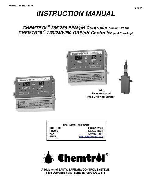
<strong>Manual</strong> 250/<strong>255</strong> – 2010<br />
INSTRUCTION MANUAL<br />
$ 20.00<br />
CHEMTROL ® <strong>255</strong>/265 PPM/pH Controller (version 2010)<br />
CHEMTROL ® 230/240/250 ORP/pH Controller (v. 4.5 and up)<br />
With<br />
New Improved<br />
Free Chlorine Sensor<br />
TECHNICAL SUPPORT<br />
TOLL FREE 800-621-2279<br />
PHONE 805-683-8833<br />
FAX 805-683-1893<br />
EMAIL<br />
support@sbcontrol.com<br />
A Division of SANTA BARBARA CONTROL SYSTEMS<br />
5375 Overpass Road, Santa Barbara CA 93111
IMPORTANT SAFETY INSTRUCTIONS<br />
Mandated by ITS Testing Laboratories, Inc<br />
1. READ AND FOLLOW ALL INSTRUCTIONS<br />
2. WARNING - To reduce the risk of injury, do not permit children to use this product unless they are closely supervised<br />
at all times.<br />
3. WARNING - Risk of Electric Shock. Connect only to a grounding type receptacle protected by a ground-fault circuit<br />
interrupter (GFCI). Contact a qualified electrician if you cannot verify that the receptacle is protected by a GFCI.<br />
(Only required for cord-connected units.)<br />
4. Do not bury cord. Locate cord to minimize abuse from lawn mowers, hedge trimmers, and other equipment. (Only<br />
required for cord-connected units.)<br />
5. WARNING - To reduce the risk of electric shock, replace damaged cord immediately. (Only required for cordconnected<br />
units.)<br />
6. WARNING - To reduce the risk of electric shock, do not use extension cord to connect unit to electric supply; provide<br />
a properly located outlet. (Only required for cord-connected units.)<br />
7. SAVE THESE INSTRUCTIONS.<br />
WARRANTY<br />
This CHEMTROL ® Electronic Controller Model ________S/N _____________________________________ is warranted by SANTA<br />
BARBARA CONTROL SYSTEMS (SBCS) to be free from defects in manufacturing and workmanship for a period of FIVE (5) YEARS from<br />
the date of purchase for the electronic module and ONE (1) YEAR for all other components. SBCS will repair or replace, at its option, any<br />
defective part during the warranty period. Labor, shipping or incidental expenses are specifically excluded from this warranty. For warranty<br />
coverage, defective parts should be returned immediately to your CHEMTROL ® Dealer or to our factory postpaid with a copy of your<br />
purchase receipt and a detailed description of the malfunction.<br />
TABLE OF CONTENTS<br />
TECHNICAL SUPPORT 1<br />
WARRANTY 2<br />
INTRODUCTION 3<br />
FREE CHLORINE 3<br />
ORP CONTROL (Models 230/250) 3<br />
PPM CONTROL (Models <strong>255</strong> and 265) 3<br />
WATER CHEMISTRY 3<br />
INPUTS AND OUTPUTS 3<br />
INSTALLATION (CH230, CH240, CH250) 4<br />
LOCATION 4<br />
SENSOR INSTALLATION (pH and ORP) 4<br />
MAIN LINE INSTALLATION 4<br />
BYPASS LINE INSTALLATION 5<br />
SENSOR CELL 5<br />
WATER FLOW 5<br />
INSTALLATION (CH<strong>255</strong> and CH265) 6<br />
PPM SENSORS 6<br />
PPM SENSOR FLOW CELL 6<br />
PPM SENSOR INSTALLATION 7<br />
ELECTRICAL 7<br />
UNINTERRUPTED POWER SUPPLY 7<br />
OPERATING VOLTAGE 7<br />
POWER TERMINAL BLOCK WIRING 7<br />
REMOTE ALARM 8<br />
FLOW SWITCH 8<br />
SETUP MENU 8<br />
ACID/BASE FEED 8<br />
SANITIZER/pH INTERLOCK 8<br />
SAFETY FLOW SWITCH 8<br />
CHEMICAL FEEDERS 9<br />
CHEMICAL FEED PUMPS 9<br />
EROSION FEEDER 9<br />
OPERATION 9<br />
PPM SENSOR CONDITIONING 9<br />
CALIBRATION OF SENSORS 9<br />
CONTROL SETPOINTS 9<br />
OVERFEED SAFETY TIMERS 9<br />
OUT-OF-RANGE ALARMS 10<br />
FEED MODE 10<br />
PROPORTIONAL FEED 10<br />
CONTROLLER RESET 10<br />
STARTUP 10<br />
DEFAULT PARAMETERS 10<br />
AUTOMATIC CONTROL 10<br />
MAINTENANCE 11<br />
GENERAL MAINTENANCE 11<br />
EFFECT OF CYANURIC ACID 11<br />
PPM SENSOR TESTING 11<br />
PPM SENSOR MAINTENANCE 11<br />
NO PPM SENSOR CLEANING 11<br />
ORP AND pH SENSOR TESTING 11<br />
ORP AND pH SENSOR CLEANING 11<br />
SENSOR REPLACEMENT 11<br />
SENSOR STORAGE 11<br />
WINTERIZING 11<br />
PORTABLE TESTER 12<br />
ORP SENSOR TESTING 12<br />
pH SENSOR TESTING 12<br />
ORP AND pH SIMULATION 12<br />
TROUBLESHOOTING 13<br />
LIST OF FIGURES 13<br />
PARTS LIST 14<br />
OPTIONS 14<br />
SPECIFICATIONS 14
<strong>Manual</strong> 250/<strong>255</strong> - 2010 Page 3<br />
INTRODUCTION<br />
The CHEMTROL ® 250 Series Controllers are microprocessorbased<br />
digital controllers designed to monitor and control the<br />
sanitizer and pH levels in swimming pools, spas, cooling towers<br />
and industrial applications.<br />
The controllers are available with three types of sensors for<br />
measurement of water acidity (pH) and of sanitizer level in either<br />
PPM (parts per million or milligrams/liter) or ORP in millivolts.<br />
This manual covers new versions (2010) of five models:<br />
• CHEMTROL ® 265 PPM/pH Controller (4-20 mA outputs),<br />
• CHEMTROL ® <strong>255</strong> PPM/pH Controller (ON/OFF outputs),<br />
• CHEMTROL ® 250 ORP/pH Controller,<br />
• CHEMTROL ® 240 pH Controller,<br />
• CHEMTROL ® 230 ORP Controller.<br />
FREE CHLORINE<br />
As shown on the dissociation curve on the right, Free Chlorine in<br />
water is in equilibrium under two forms:<br />
• Molecular HOCl, a strong sanitizer and oxidizer,<br />
• Ionized OCl-, a weak sanitizer and oxidizer.<br />
At a pH of 7.5, the two forms are in equal proportions of 50%<br />
each. At lower pH values, HOCl predominates. At higher pH<br />
values, OCl- is dominant.<br />
ORP CONTROL (Models 230/250)<br />
The ORP sensor shows the voltage (in mV) produced by<br />
oxidizers in water.<br />
It responds to strong oxidizers, such as HOCl and its bromine<br />
equivalent HOBr. It also responds to other strong oxidizers that<br />
are used in water treatment, such as Ozone (O3) or Potassium<br />
Monopersulfate (KSO3).<br />
Because HOCl is the primary oxidizer, the signal of the ORP<br />
sensor decreases with increasing pH values.<br />
It is not specific to chlorine or bromine and responds to other<br />
oxidizers.<br />
The chlorine or bromine concentration required to generate a<br />
desired ORP value varies with pH and overall water quality,<br />
particularly Total Dissolved Solids (TDS) concentration, organic<br />
load and cyanuric stabilizer concentration.<br />
The ORP setpoint default value on the controller is 700 mV,<br />
which is recommended to kill germs and bacteria and maintain<br />
good water quality.<br />
PPM CONTROL (Models <strong>255</strong> and 265)<br />
Direct FREE CHLORINE measurement including:<br />
- free chlorine (HOCl and OCL-) and<br />
- chlorinated isocyanurates if present, corresponding to the<br />
DPD1 test.<br />
The controller displays the concentration of Total Free Chlorine<br />
(HOCl + OCl-) in PPM (parts per million or milligrams/liter). It<br />
does not respond to Bromine and/or oxidizers.<br />
The Free Chlorine display does not vary up to a pH of 7.8.<br />
The PPM setpoint default value on the controller is 1.0 ppm,<br />
which is recommended to kill germs and bacteria and maintain<br />
good water quality. It can be adjusted to meet local conditions<br />
and Health Department requirements.<br />
WATER CHEMISTRY<br />
Before starting automatic control, test the water chemistry to<br />
make sure that the pH, Cyanuric Acid and Total Dissolved Solids<br />
are within the ranges recommended by the National Spa and<br />
Pool Institute (NSPI).<br />
The pH should be adjusted manually within 7.4 to 7.6. If it is<br />
below 7.0 or above 8.0, the controller will show an alarm<br />
condition and prevent feeding (programmable option).<br />
To stabilize chlorine against solar UV radiation, a cyanuric acid<br />
level of 20 to 25 ppm is ideal. However, this level can be quickly<br />
exceeded with stabilized chlorine (dichlor or trichlor). Note that<br />
many Health Department codes do not allow stabilizer levels<br />
above 100 ppm. If above 100 ppm, this results in chlorine lock<br />
that shows as low ORP readings even with high chlorine levels.<br />
The Total Dissolved Solid (TDS) level should be below 2,000<br />
ppm. If higher, the water is full of organic and inorganic<br />
impurities and should be dumped and replaced partially or<br />
completely.<br />
For effective pH control, the Total Alkalinity should be between<br />
80 to 120 ppm. If too low, the pH will bounce and be hard to<br />
control. If too high, the pH will be hard to change.<br />
INPUTS AND OUTPUTS<br />
Figure 1 - Equilibrium of Free<br />
Chlorine<br />
Depending on the model number, the inputs include one or two<br />
sensors:<br />
• a PPM sensor to monitor free chlorine concentration,<br />
• an ORP sensor to monitor ORP or Redox,<br />
• a pH sensor and a safety flow switch (optional).<br />
The outputs are two relays for sanitizer and pH feed - acid or<br />
base - plus a relay for an optional remote alarm or telephone<br />
dialer.
<strong>Manual</strong> 250/<strong>255</strong> - 2010 Page 4<br />
INSTALLATION (CH230, CH240, CH250)<br />
Figure 2 – CH250 Installation on<br />
Main Line<br />
LOCATION<br />
Mount the controller cabinet on a wall in a secure location, as<br />
shown on the schematic:<br />
• more than 10' (3 m) away from the water edge to<br />
comply with electrical code requirements,<br />
• if possible, not more than 10' (3 m) of the main<br />
recirculation line or of the bypass line. The sensors<br />
come with standard 10-foot (3-m) cables. If needed,<br />
you can order 25 or 50-ft BNC extension cables from<br />
your dealer.<br />
• not exposed to direct sunlight,<br />
• easily accessible to maintenance personnel,<br />
• if possible in a separate room, or in a well- ventilated<br />
room as far away as possible from corrosive chemicals<br />
and storage tanks,<br />
• at a safe distance from power transformers, pump<br />
motors or high voltage power lines<br />
• safe from unauthorized access or vandalism.<br />
SENSOR INSTALLATION (pH and ORP)<br />
MAIN LINE INSTALLATION<br />
On smaller installations (2 “ pipe diameter), the sensors can be<br />
mounted directly on the main recirculation line).<br />
Use only the 2x2x1/2 in. SST reducing tees without reducers (Do<br />
not install the sensors near an elbow or a constriction where<br />
there might be excessive turbulence.<br />
Install the tees after the pump and filter. Insert the sensor tip<br />
down so that the tip is about 1/4 inch (1 cm) in the water. The<br />
sensors should be readily accessible for servicing but not<br />
exposed to physical damage.<br />
Tighten the compression fitting by hand only to avoid breaking<br />
the internal glass tube in the sensors. Do not use a wrench!<br />
Save the sensor caps for storage or shipping of the sensors.<br />
When in storage or shipping, add salt water in the cap to keep the<br />
sensors from drying out. During winter, store the sensors above<br />
freezing temperature.<br />
The sensors can be mounted three different ways:<br />
• directly on the main recirculation line) (2 in. pipe only),<br />
• on a 1/2 in. bypass line as shown,<br />
• even better, in a sensor cell mounted on the bypass line<br />
(Figure 5).<br />
Figure 3 – ORP or pH Sensor<br />
in PVC Tee
<strong>Manual</strong> 250/<strong>255</strong> - 2010 Page 5<br />
Figure 4 – CH250 Installation with<br />
Bypass Line<br />
BYPASS LINE INSTALLATION<br />
To facilitate installation of the sensors and to assure a smooth<br />
and steady flow of water by the sensors, it is recommended to<br />
install the optional Bypass Line Assembly (P/N BPL-0.5). As<br />
shown in Figure 4, it includes:<br />
- two (2) compression gland fittings (1/2" MPT),<br />
- two (2) PVC tees (1/2" SST),<br />
- one (1) in-line Y-filter (3/4" MPT),<br />
- one (1) in-line flowmeter (1/2" FPT),<br />
- one (1) rotary safety flow switch (1/2" FPT),<br />
- two (2) ball valves (1/2" SxS) for flow adjustment and for<br />
isolating the bypass line during backwashing of the filter and<br />
other maintenance operations,<br />
- one (1) spigot (1/2" SxS) for water sampling and testing.<br />
To check the water flow in the bypass line, start the main<br />
recirculation pump. Open both the intake and the return valves<br />
on the bypass line and read the flow rate on the flowmeter. It<br />
should be in the middle of the range, i.e. about 2-3 gpm (about 8<br />
to 12 l/min). If the water flow is too high, you can turn down the<br />
valve on the RETURN SIDE of the bypass line. If there is no<br />
water flow, replumb the bypass line as shown on the schematic.<br />
NOTE: Most common installation problems with bypass line<br />
installations are caused by faulty hydraulics.<br />
The Bypass Line Assembly should be installed exactly as shown<br />
on Figure 4. In particular, make sure to install the flowmeter in a<br />
vertical position and to install the flow switch downstream (after<br />
the sensors) to assure a smooth flow of water near the sensors.<br />
SENSOR CELL<br />
For additional ease of installation and maintenance, it is also<br />
recommended to mount the sensors in the optional Flow Cell,<br />
Assembly as shown in Figure 5. It includes:<br />
• the sensor cell with air vent and clear cover,<br />
• two (2) compression fittings for the sensors,<br />
• one (1) water sampling tap<br />
• two (2) ball valves for controlling the water flow in and out.<br />
WATER FLOW<br />
Proper flow of water past the sensors is essential to obtaining<br />
good readings.<br />
Figure 5 – Flow Cell Assembly<br />
To ensure proper water flow, make sure that the bypass line is<br />
properly connected. As shown in Figure 4, the intake side should<br />
be on the effluent side of the recirculation system, i.e. after the<br />
filter. The return side should be to a low-pressure area - such as<br />
the vacuum side before the recirculation pump, or downstream<br />
after the heater, or atmospheric pressure in the pit of a vacuum<br />
sand filter or balancing tank.
<strong>Manual</strong> 250/<strong>255</strong> - 2010 Page 6<br />
INSTALLATION (CH<strong>255</strong> and CH265)<br />
Figure 6 – CH<strong>255</strong>/265 Installation<br />
with 2 Flow Cells<br />
PPM SENSORS<br />
The following new, improved PPM Sensors (Model 2010) are<br />
available with the CH<strong>255</strong> and CH265 controllers:<br />
- PPM002 for 0-2 PPM (mg/l) of Free Chlorine<br />
- PPM010 for 0-10 PPM (mg/l) of Free Chlorine<br />
Both use the same membrane Part Number PPMM01<br />
- PPM200 for 0-200 PPM (mg/l) of Free Chlorine with<br />
membrane part number PPMM02<br />
- PPMSLT 0-10 PPM Membraneless Sensor for electrolytic<br />
chlorine generators.<br />
NOTES<br />
1. These new sensors are not affected by cyanuric acid -<br />
therefore the new CH<strong>255</strong>/265 (Version 2010) have no GAIN<br />
FACTOR adjustment.<br />
2. All sensors use the same flow cell PPMCLL and do not require<br />
the plastic spacer ring.<br />
PPM SENSOR FLOW CELL<br />
The PPM Sensor must be installed in the specially designed flow<br />
cell for better water flow control. Install the flow cell on a bypass<br />
line with 3/8” tubing as shown above.<br />
SPAS<br />
Figure 7 - PPM Sensor Cell<br />
For a spa, it is recommended to increase the flow rate sufficiently<br />
to avoid the formation of air bubbles and to install the cell<br />
horizontally with the inflow coming in from the bottom.<br />
Make sure that the bypass line is located after the filter and that<br />
there is a sufficient but not excessive flow of water. The<br />
recommended flow rate is between 20 to 100 l/h (0.1 to 0.6<br />
gal/min.) with a best value of about 30l/h (0.2 gal/min).
<strong>Manual</strong> 250/<strong>255</strong> - 2010 Page 7<br />
PPM SENSOR INSTALLATION<br />
The new PPM Sensors are shipped in a molded foam package<br />
containing:<br />
- One (1) chlorine sensor with warranty serial number,<br />
- One (1) compression fitting with O-ring,<br />
- One (1) electrolyte cap with membrane,<br />
- One (1) electrolyte bottle and screw-on filling tip,<br />
- One (1) screwdriver (not needed if pre-wired).<br />
In order to prevent serious damage to the sensor, be careful not<br />
to touch the membrane or the electrodes. To facilitate shipment<br />
and storage of the sensor, it is not fitted with the electrolyte cap<br />
until ready for installation. The sensor cap must be filled with the<br />
electrolyte solution immediately before usage and emptied during<br />
storage.<br />
Fill the sensor cap with the electrolyte taking care to prevent air<br />
bubbles. Fill the cap to the bottom of the threaded section.<br />
Thread the sensor into the cap as far as it will go while making<br />
sure not to touch the membrane film at the bottom with your<br />
fingers. Excess air and electrolyte may escape through the hole<br />
below the rubber seal. Wipe any excess electrolyte with a soft<br />
tissue. Contact your CHEMTROL (R) dealer if you need additional<br />
electrolyte.<br />
Slide the O-ring over the sensor tip up to the compression ring.<br />
Finally, insert the sensor with O-ring in the flow cell and make it<br />
finger tight.<br />
For best performance, it is recommended to change the<br />
membrane cap and electrolyte at least once a year.<br />
PPMSLT SENSOR<br />
Figure 8 - PPM Sensor Package<br />
The PPMSLT sensor does not use a membrane and has a<br />
different open-through cap that holds the electrolyte solution<br />
around the electrodes glass shaft. Because this cap is opened<br />
from both sides, the procedure to fill it with the necessary<br />
electrolyte is slightly different in that you must do so with the<br />
accompanied lid on before fully screwing that cap onto the<br />
electrodes then finally removing that lid.<br />
The PPMSLT sensor is the only sensor that requires cleaning of<br />
its gold electrodes tip and you do so with the small special<br />
abrasive cleaner the sensor is shipped with.<br />
ELECTRICAL<br />
Make sure to follow all local electrical codes.<br />
Always interlock the controller with the timer on the main<br />
power supply (see Error! Reference source not found.) to<br />
prevent injection of chemicals when the recirculation pump is not<br />
running.<br />
UNINTERRUPTED POWER SUPPLY<br />
It is highly recommended to use a power conditioning protection<br />
system, such as a UPS (Uninterrupted Power <strong>Supply</strong>) to protects<br />
the integrated circuits (Ics) in the controller that are susceptible to<br />
power spikes, lightning, etc.<br />
To prevent electrical shock, make sure that the power is<br />
disconnected before opening the cabinet.<br />
The Mother Board is mounted behind the front panel and the<br />
Power Board (Figure 9) in the back of the controller.<br />
OPERATING VOLTAGE<br />
The operating voltage is factory set for 110, 230 or 24 VAC.<br />
Make sure to check the voltage before installation to avoid<br />
damage to the control board and void the warranty. 110 V units<br />
have a power cord with a 3-prong plug. 230 V units have bare<br />
wires. 24 V units do not have a transformer. You can also check<br />
Jumpers JP5 on the Power Board (Figure 9).<br />
All outputs voltages are the same as the input voltages.<br />
POWER TERMINAL BLOCK WIRING<br />
HOT CMN GND<br />
+ 5V<br />
Red<br />
SIG<br />
White<br />
GND<br />
Black<br />
SIG GND HOT CMN GND HOT CMN GND HOT CMN GND<br />
SANITIZER FEED<br />
AC OUT<br />
PADDLE WHEEL<br />
DC IN<br />
FLOW<br />
SWITCH<br />
POWER<br />
AC IN<br />
ALARM<br />
AC OUT<br />
ACID/BASE FEED<br />
AC OUT
<strong>Manual</strong> 250/<strong>255</strong> - 2010 Page 8<br />
LINE 1…………..BLACK (HOT)<br />
LINE 2…………..WHITE (NEUTRAL)<br />
GROUND………..GREEN (GROUND)<br />
BLUE TERMINAL BLOCK<br />
PADDLE WHEEL FLOW SWITCH<br />
TB2-1 (+5v) Red Wire<br />
TB2-2 Signal White Wire<br />
TB2-3 Ground Black Wire<br />
FLOW SWITCH<br />
TB2-4<br />
TB2-5<br />
Signal Dry Contact<br />
Ground Flow Switch<br />
ALARM JUMPERS<br />
The alarm is hot by default.<br />
JP6 jumpers for the alarm relay output are set on pins 1-2 and<br />
3-4 by factory.<br />
Jump pins 2-3 instead for dry contact alarm function.<br />
Figure 9 – Power Board<br />
FUSE CONFIGURATION<br />
F1 + F2 5A Slow blow Sanitizer feed<br />
F3 + F4 5A Slow blow Acid/Base feed<br />
F5 + F6 5A Slow blow Alarm<br />
F7 2.50A Slow Blow For 24VAC Controllers<br />
F7 1.0A Slow Blow For 120/240VAC Controllers<br />
REMOTE ALARM<br />
The remote alarm is connected through the terminal block as<br />
shown below. It can be used to activate a remote alarm such as<br />
a light, a buzzer, or a bell, or even an automatic telephone dialer<br />
with voice messaging capability.<br />
The Alarm Jumpers JP6 (Figure 9) are normally set for a HOT<br />
(powered) contact with two jumpers in the 1-2 and 3-4 positions.<br />
For a dry (N.O.) contact, set one jumper only in position 2-3.<br />
FLOW SWITCH<br />
Note: with a bypass line, a Safety Flow Switch is<br />
absolutely required to prevent accidental feeding of<br />
chemicals if the line is shut off or obstructed.<br />
The rotary paddlewheel flow switch connects to the controller<br />
terminal block as shown below using the + 5V power input.<br />
DO NOT CONNECT TO HIGH VOLTAGE.<br />
A blade flow switch uses a dry contact that connects as shown<br />
below to interrupt the power output. Make sure to orient the flow<br />
switch in the direction of flow.<br />
SETUP MENU<br />
Upon startup, the Setup Menu is displayed. You can also recall it<br />
at any time by pressing both arrow keys simultaneously.<br />
ACID/BASE FEED<br />
The Setup Menu first displays PHF (pH Feed) and either AC for<br />
Acid Feed (default value) or bA for Base Feed. Press either<br />
arrow to change the setting.<br />
Acid Feed is used for all basic (alkaline) sanitizers: liquid chlorine<br />
(sodium hypochlorite NaOCl) or dry chlorine (calcium<br />
hypochlorite Ca(OCl) 2). Base Feed is used only for acidic<br />
sanitizers (trichlor tablets).<br />
SANITIZER/pH INTERLOCK<br />
The Setup Menu then displays IL for Interlock and either 0 for<br />
OFF or 1 for ON (default value).<br />
The Sanitizer/pH Interlock is a safety feature designed to<br />
deactivate the sanitizer feed when the pH is out of range. This is<br />
particularly important with liquid chlorine, a strong basic chemical<br />
that raises the pH of the water.<br />
SAFETY FLOW SWITCH<br />
The Setup Menu then displays FLO for Flow Switch with either 0<br />
for OFF or 1 for ON (default value).
<strong>Manual</strong> 250/<strong>255</strong> - 2010 Page 9<br />
CHEMICAL FEEDERS<br />
Make sure to inject all the chemicals downstream of the sensors<br />
to avoid false readings, and downstream of all equipment (pump,<br />
filter, heater) to avoid corrosion.<br />
CHEMICAL FEED PUMPS<br />
Install the feed pumps for liquid chlorine, calcium hypochlorite or<br />
dichlor solutions as shown in Error! Reference source not found.,<br />
according to the manufacturer’s instructions.<br />
EROSION FEEDER<br />
With an erosion feeder for bromine or chlorine tablets, install a<br />
solenoid valve on the intake side of the bypass line to the erosion<br />
feeder as shown in Figure 10.<br />
Figure 10 - Erosion Feeder Installation<br />
OPERATION<br />
PPM SENSOR CONDITIONING<br />
IMPORTANT: DO NOT CONNECT THE PPM SENSOR before<br />
the conditioning procedure is completed. Warranty may be void<br />
if sensor is powered without proper conditioning.<br />
Before using the PPM sensor for the first time – or after long<br />
storage in air – it is important to hydrate the sensor. Remove the<br />
sensor cap and place the sensor for at least 30 to 60 minutes in<br />
water containing a small amount of chlorine without connecting it<br />
to the controller.<br />
Please note that the sensor’s time response for accurate chlorine<br />
reading could take up to 30 minutes after first hydration and up to<br />
15 minutes to stabilize after each water chemistry change.<br />
CALIBRATION OF SENSORS<br />
No calibration is required for the ORP sensor.<br />
To calibrate the PPM and pH sensors, test the water with a<br />
reliable, fresh test kit (DPD and Phenol Red). Note the values<br />
and compare to the display values. Re-calibrate if needed, as<br />
follows:<br />
- press [CALIBRATION],<br />
- press [PPM] or [pH]: the display flashes,<br />
- use the [UP] and [DOWN] arrows to adjust the value,<br />
- press [CALIBRATION] again to save the new value.<br />
To calibrate the PPM sensor, use a DPD #1 test kit for free<br />
chlorine. It is recommended to do the first calibration 2 hours<br />
after startup and to repeat it after 24 h.<br />
CONTROL SETPOINTS<br />
The PPM setpoint is factory set at 1.0 ppm.<br />
The ORP setpoint is factory set at 700 mV, which is<br />
recommended to maintain water quality by killing germs and<br />
bacteria. There is no need for ORP calibration.<br />
The pH setpoint is factory set at 7.5, which is recommended for<br />
pool and spa applications.<br />
To change a control setpoint:<br />
- press [SETPOINT],<br />
- press [PPM], [ORP] or [pH] : the display flashes,<br />
- use the [UP] and [DOWN] arrows to adjust the setpoint,<br />
- press [SETPOINT] again to save the new value.<br />
OVERFEED SAFETY TIMERS<br />
The internal safety timers are designed to alert the operator in<br />
case of overfeeding of chemicals as a result of mechanical or<br />
electronic failure or empty containers.<br />
The timers are factory set at 15 minutes for PPM or ORP and 5<br />
minutes for pH. This is normally sufficient to reach the setpoint.<br />
At that time feeding stops and the timer resets to zero. If the limit<br />
is reached however, the feeder is deactivated, the alarm turned<br />
on and the display flashes the overfeed time. The operator<br />
should then check the chemical feeders, feed lines and tanks.<br />
After correcting the problem, the safety timer is reset by switching<br />
the feed mode to OFF and then back to AUTO.<br />
To change the limits of a safety timer:<br />
- press [SAFETY TIMER],<br />
- press [ORP], [PPM] or [pH] : the display flashes,<br />
- use the [UP] and [DOWN] arrows to adjust the value,<br />
- press [SAFETY TIMER] again to save the new value.<br />
CAUTION: Increasing the limit on a safety timer may cause<br />
overfeeding of chemicals.
<strong>Manual</strong> 250/<strong>255</strong> - 2010 Page 10<br />
OUT-OF-RANGE ALARMS<br />
The out-of-range alarms are factory set at 650 to 900 mV for<br />
ORP, 0.3 to 6.0 for PPM and 7.0 to 8.0 for pH. If the ORP or PPM<br />
readings are below the low limit, the red LED alarm flashes but<br />
sanitizer feed continues.<br />
If the pH limits are exceeded, the red LED alarm flashes and all<br />
feeders (pH and sanitizer) are deactivated - unless the<br />
sanitizer/pH interlock is defeated (see below).<br />
To change an alarm limit:<br />
- press [LOW LIMIT] or [HIGH LIMIT],<br />
- press [PPM], [ORP] or [pH]: the display flashes,<br />
- use the [UP] and [DOWN] arrows to adjust the value,<br />
- press [LOW LIMIT] or [HIGH LIMIT] again.<br />
Figure 11 - ON/OFF Control<br />
CAUTION: Increasing the out-of-range limits may cause<br />
overfeeding of chemicals.<br />
FEED MODE<br />
The feed mode for the sanitizer or pH can be set to OFF, <strong>Manual</strong><br />
or Automatic. To select the desired feed mode, press [PPM],<br />
[ORP] or [pH] until the corresponding LED indicator light is<br />
illuminated. There is a short delay before activation. (Note:<br />
Holding the switch for more than 5 seconds resets the setpoint<br />
and calibration for [PPM], [ORP] or [pH] to original factory<br />
values).<br />
.<br />
PROPORTIONAL FEED<br />
Figure 12 - Proportional Control<br />
There are two ways to control the feed rate.<br />
In standard ON/OFF control (Figure 11), the feed rate remains<br />
constant until the setpoint is reached, whereupon it stops.<br />
In the Proportional Zone, activation of the chemical feeder is<br />
based on 1-minute cycles with varying ratios of ON and OFF feed<br />
times. As the sensor reading approaches the setpoint value, the<br />
ON portion of the cycle decreases progressively. During the OFF<br />
portion, the feed light flashes continuously to indicate that the<br />
controller is under proportional control.<br />
In proportional control (Figure 12), the feed rate decreases<br />
progressively as it approaches the setpoint. Proportional control<br />
is particularly useful to avoid overfeeding of chemicals in small<br />
bodies of water.<br />
CONTROLLER RESET<br />
The CHEMTROL ® controller saves all user-defined values as<br />
well as factory defaults in its internal non-volatile memory.<br />
Therefore, user-modified setpoints and acid/base feed modes will<br />
not be lost in the event of power failure and the factory default<br />
values can be restored at any time.<br />
To reset the setpoint and calibration values to the original factory<br />
values, press and hold [PPM], [ORP] or [pH] for 5 seconds.<br />
DEFAULT PARAMETERS<br />
STARTUP<br />
PPM ORP pH<br />
Setpoint 1.0 ppm 700 mV 7.5<br />
High/Low Alarms 0.3/6 ppm 650/900 mV 7.0/8.0<br />
Overfeed Safety Alarm 15 min. 15 min. 5 min.<br />
Proportional Bandwidth 1% 1% 1%<br />
AUTOMATIC CONTROL<br />
1. Run the recirculation pump with both sensors in line at least 30<br />
minutes to stabilize the sensor readings.<br />
2. Turn the controller on. The displays will show:<br />
a. the software version number,<br />
b. [pHF] with [AC] for Acid feed or [bA] for Base feed,<br />
c. [IL] with 0 or 1 if the sanitizer/pH interlock is ON,<br />
d. [FLO] with 0 or 1 if the flow switch is ON.<br />
e. the sensor readings.<br />
3. Press [ORP] or [PPM] until the feed control light is on AUTO.<br />
4. Press [pH] until the feed control light is on AUTO.<br />
5. After 30 minutes, test the pH of the water with a Phenol Red<br />
test kit. Adjust the pH calibration if needed.<br />
6. Test the free chlorine or bromine ppm in the water with a DPD<br />
test kit. Adjust the PPM or ORP setpoint if required.<br />
7. Test the water regularly as required by local health authorities.
<strong>Manual</strong> 250/<strong>255</strong> - 2010 Page 11<br />
MAINTENANCE<br />
The CHEMTROL ® controller is virtually maintenance free. The<br />
enclosure and front panel can be cleaned with a soft cloth<br />
moistened with a mild soap and water solution or a glass cleaner.<br />
Do not use abrasives or harsh chemicals.<br />
GENERAL MAINTENANCE<br />
For commercial and public pools, it is important to test and record<br />
the water chemistry readings in compliance with Health<br />
Department requirements using a good quality manual test kit.<br />
Adjust the pH, ORP or PPM calibration and setpoint as required.<br />
It is important to note that changes in pH, cyanuric acid<br />
concentration, TDS (total dissolved solids), and use of additional<br />
or alternative sanitizers will all impact the primary sanitizer<br />
residual level in comparison to ORP. To maintain a consistent<br />
sanitizer residual in parts-per-million (ppm), adjust the ORP<br />
setpoint as required.<br />
EFFECT OF CYANURIC ACID<br />
Increasing cyanuric acid levels reduce the concentration of free<br />
chlorine HOCl in water. This affects the effectivity of the sanitizer,<br />
as shown by reduced readings for ORP (Model 250) or PPM<br />
(Model <strong>255</strong>).<br />
The controller reacts by adding more chlorine to compensate for<br />
the reduced effectivity. The only remedy is to replace all or part<br />
of the water until the cyanuric acid level is reduced.<br />
PPM SENSOR TESTING<br />
To test the PPM sensor, use a DC Voltmeter and connect it to the<br />
HOCl and Ground terminals on the Mother Board, with the PPM<br />
sensor in chlorinated water. You should read 2.6 V or higher.<br />
PPM SENSOR MAINTENANCE<br />
There is no special maintenance requirements except to make<br />
sure that the membrane remains clean and to remove the sensor<br />
to prevent freezing in winter.<br />
The sensor is covered with a standard manufacturer’s warranty of<br />
2 years. Under proper water conditions, the membrance should<br />
last 1 to 2 years. Do not reuse the membrane if removed.<br />
Replace with a new membrane.<br />
NO PPM SENSOR CLEANING<br />
Do not clean the PPM sensor.<br />
membrane and void the warranty.<br />
Cleaners will damage the<br />
ORP AND pH SENSOR TESTING<br />
To test the sensors on line, carefully add a small amount of white<br />
vinegar or dilute acid solution in the skimmer. After a few<br />
minutes:<br />
- the pH reading should go DOWN.<br />
- the ORP reading should go UP.<br />
If you still get no response or a sluggish response, clean or<br />
replace the sensors as soon as possible.<br />
For additional testing, use the PORTA-PROBE II (Figure 13)<br />
Portable Tester, as shown on the next page.<br />
ORP AND pH SENSOR CLEANING<br />
The sensor tips must be kept clean and free from chemical<br />
deposits and contamination to function properly. After saturation<br />
in pool or spa water, the sensors may need to be cleaned on a<br />
weekly or monthly basis depending on the water quality and other<br />
facility-specific characteristics. Slow response and inconsistent<br />
readings are indications that the sensors are in need of cleaning.<br />
To clean a sensor, carefully remove it from the compression<br />
fitting. Clean the tip of the sensor with a mild liquid detergent<br />
(Joy, etc.) solution. Rinse with fresh water and soak the sensor in<br />
a mild acid solution for five minutes. Rinse with fresh water and<br />
reinstall the sensor.<br />
SENSOR REPLACEMENT<br />
For optimum controller performance, always use genuine<br />
CHEMTROL ® replacement sensors. For preventive maintenance<br />
it is also recommended to replace the sensors on an annual basis<br />
or as performance diminishes.<br />
SENSOR STORAGE<br />
Extended exposure to atmospheric conditions will cause the ORP<br />
and pH sensor tips to dry out.<br />
The PPM sensor should be stored dry and electrically<br />
disconnected.<br />
Always remove and properly store the sensors if the pool or spa<br />
is to be winterized or inactive. Store the sensors with the original<br />
cap provided, making sure that each cap is filled with the original<br />
storage solution or salt water. If the storage containers have<br />
been misplaced, store the sensors individually in small glass or<br />
plastic containers with clean water covering the sensor tips.<br />
WINTERIZING<br />
The sensors should be prepared for storage as outlined above<br />
and protected from freezing. Although the controller is designed<br />
to withstand a broad temperature range, winter storage in a<br />
secure location at normal room temperature is recommended.
<strong>Manual</strong> 250/<strong>255</strong> - 2010 Page 12<br />
PORTABLE TESTER<br />
The PORTA-PROBE II (Figure 13) is a battery-operated portable tester/signal<br />
generator designed to test the ORP and pH sensors and to generate calibrated<br />
signals to test the controller. It is supplied with a 9V battery and a pair of shielded<br />
cables with BNC connectors.<br />
The PORTA-PROBE II is not used to calibrate the sensors. This should be done<br />
with a chemical test kit, such as DPD for Free Chlorine and Phenol Red for pH.<br />
It can also be used to test the TDS and Temperature sensors on the CHEMTROL ®<br />
PC or CT controllers.<br />
Figure 13 - Portable Tester<br />
ORP SENSOR TESTING<br />
Set the Mode Switch to TESTING. Connect the ORP sensor to the ORP BNC<br />
connector on the tester. Turn the Selector Knob to ORP.<br />
Place the sensor in balanced water (pH = 7.5 / PPM = 1.0 Cl). You should get an<br />
ORP reading within 650 to 750 mV.<br />
Place the sensor in an acid solution. You should get a HIGH POSITIVE reading.<br />
Place the sensor in a BLEACH (liquid chlorine) solution. You should get a LOW<br />
POSITIVE reading.<br />
pH SENSOR TESTING<br />
The PORTA-PROBE II shows actual pH sensor readings in millivolts, as shown on<br />
the Table on the right.<br />
Set the Mode Switch to TESTING. Connect the pH sensor to the pH BNC connector<br />
on the tester. Turn the Selector Knob to pH.<br />
Place the pH sensor in nearly neutral water (pH = 7.5). You should get a pH reading<br />
of about -30 mV.<br />
Place the sensor in an acid solution. You should get a HIGH POSITIVE reading.<br />
Place the sensor in a BLEACH solution. You should get a HIGH NEGATIVE<br />
reading.<br />
The linear scale on the right shows the conversion of millivolt readings into pH units.<br />
ORP AND pH SIMULATION<br />
Set the Mode Switch to SIMULATOR.<br />
Use the two coaxial cables to connect the BNC connectors on the tester to the<br />
respective BNC connectors on the controller.<br />
Set the Selector Knob to either pH or ORP Simulator. The readings on the<br />
controller should match the readings of the tester display (unless offset by<br />
calibration of the pH probe).<br />
The outputs of the ORP and pH simulators can be adjusted with the two small knobs<br />
located below the digital display. The ORP range is 0 to 1,000 mV.. The pH range<br />
is -180 to + 180 mV (10 to 4 on the pH scale). These outputs can be used to test for<br />
proper operation of the feed and alarm features of the controller.<br />
mV<br />
pH Scale<br />
pH<br />
+420 0<br />
+30 6.5<br />
0 7.0<br />
-6 7.1<br />
-12 7.2<br />
-18 7.3<br />
-24 7.4<br />
-30 7.5<br />
-60 8.0<br />
-90 8.5<br />
-420 14.0<br />
NOTE 1: Due to signal stabilization, the readings on the controller may take up to 10<br />
seconds to reach full value.<br />
NOTE 2: ORP and pH signals can be generated simultaneously but only one signal<br />
is displayed.
<strong>Manual</strong> 250/<strong>255</strong> - 2010 Page 13<br />
TROUBLESHOOTING<br />
No lights on. 1. Check the circuit breaker and/or receptacle for proper operation. Connect to functional<br />
grounding-type GFCI protected power source.<br />
2. Check for a damaged power connector.<br />
3. Check internal fuse (1A slow blow) marked F7 on Power Board.<br />
Alarm lights and buzzer<br />
on.<br />
1. Verify that the filtration system is functioning properly, water flow is adequate and water chemistry is<br />
in balance.<br />
2. Verify that sensor and power cables are properly connected to the respective connectors on the<br />
controller.<br />
3. Check the operation of the chemical feeders (pumps or erosion feeder).<br />
4. Verify that the (optional) flow sensor is properly installed.<br />
Illogical value displays. 1. The sensor cable connections may be reversed. Verify that the sensor cables are properly connected<br />
to their respective BNC connectors on the controller unit.<br />
2. Verify that the filtration system is functioning properly, the water flow is adequate, and the water<br />
chemistry is in balance.<br />
No Chemical feed.<br />
No Sanitizer feed.<br />
1. Check FLO setting in Setup Menu and safety flow switch on bypass line if applicable.<br />
1. Make sure the AUTO feed light is on.<br />
2. Check the setpoint.<br />
3. Check relay fuse (5A slow blow) marked F1 and F2 on Power Board.<br />
No Acid/Base feed. 1. Check pHF setting in Setup Menu for Acid or Base feed.<br />
2. Make sure the AUTO feed light for pH is on.<br />
3. Check the pH setpoint.<br />
4. Check pH relay fuse (5A slow blow) marked F3 and F4 on Power Board.<br />
Chlorine or bromine<br />
residual too high or too<br />
low.<br />
pH requires frequent<br />
calibration.<br />
Inconsistent or slow<br />
readings.<br />
Chemical feeder runs<br />
continuously.<br />
pH or Sanitizer<br />
overshoots setpoint.<br />
pH or Sanitizer does not<br />
reach setpoint.<br />
1. Remember that the pH, cyanuric acid concentration, total dissolved solids, and use of additional or<br />
alternative sanitizers will all impact the sanitizer residual level in comparison to ORP. Consider the<br />
impact of any chemicals recently added to the pool or spa.<br />
2. Check and adjust the setpoint.<br />
1. Clean or replace the sensor as outlined in the maintenance section.<br />
1. Verify that the sensor cables are properly connected to their respective BNC connectors on the<br />
controller unit.<br />
2. Clean the sensors as outlined in the maintenance section.<br />
3. Check to verify that all the electrical equipment in the facility pump room is properly grounded.<br />
4. Replace the sensors if needed.<br />
1. Make sure the AUTO feed mode is selected.<br />
2. Verify that the chemical feeders are properly connected to their respective connectors on the<br />
controller unit.<br />
1. Increase the width of the proportional zone.<br />
2. Check the dilution of sanitizer or acid/base solution.<br />
1. Decrease the width of the proportional zone.<br />
2. Increase the concentration of sanitizer or acid/base solution.<br />
3. Check chemical feeders for proper operation.<br />
LIST OF FIGURES<br />
Figure 1 - Equilibrium of Free Chlorine............................................3<br />
Figure 2 – CH250 Installation on Main Line.....................................4<br />
Figure 3 – ORP or pH Sensor .........................................................4<br />
Figure 4 – CH250 Installation with Bypass Line ..............................5<br />
Figure 5 – Flow Cell Assembly........................................................5<br />
Figure 6 – CH<strong>255</strong>/265 Installation with 2 Flow Cells .......................6<br />
Figure 7 - PPM Sensor Cell.............................................................6<br />
Figure 8 - PPM Sensor Package.....................................................7<br />
Figure 9 – Power Board...................................................................8<br />
Figure 10 - Erosion Feeder Installation ...........................................9<br />
Figure 11 - ON/OFF Control..........................................................10<br />
Figure 12 - Proportional Control ....................................................10<br />
Figure 13 - Portable Tester............................................................12
<strong>Manual</strong> 250/<strong>255</strong> - 2010 Page 14<br />
PARTS LIST<br />
MB250/<strong>255</strong><br />
PB250/<strong>255</strong><br />
ORP<br />
pH<br />
PKT-2.0<br />
PKT-1.5<br />
PPM002<br />
PPM010<br />
PPM200<br />
PPMSLT<br />
PPMCLL<br />
PPMM01<br />
PPMM02<br />
Mother Board for CH250 or CH<strong>255</strong> (specify voltage)<br />
Power Board for CH250 or CH<strong>255</strong> (specify voltage)<br />
ORP sensor with 10-ft BNC cable<br />
pH sensor with 10-ft BNC cable.<br />
Set of two (2) PVC tees and compression fittings for 2 in. (50 mm) line<br />
Set of two (2) PVC tees and compression fittings for 1 1/2 in. (37 mm) line<br />
0-2 PPM Chlorine Sensor with connector<br />
0-10 PPM Chlorine Sensor with connector<br />
0-200 PPM Chlorine Sensor with connector<br />
0-10 PPM Membraneless Sensor for Electrolytic Salt Generator with connector<br />
Flow Cell for Chlorine sensor<br />
Membrane for PPM002/PPM010 Sensors<br />
Membrane for PPM200<br />
OPTIONS<br />
BPL-0.5<br />
PWFS<br />
FCA<br />
XC25<br />
XC50<br />
DIAL<br />
1/2 in. bypass line assembly with Y-filter, flowmeter, safety flow switch, two (2) shutoff valves and sampling tap.<br />
Rotary paddle-wheel safety flow switch.<br />
Machined transparent polycarbonate flow cell assembly for sensors.<br />
Sensor cable extension with BNC connectors, 25-ft (8 m).<br />
Sensor cable extension with BNC connectors, 50-ft (16 m).<br />
Telephone dialer with voice messaging.<br />
SPECIFICATIONS<br />
Cabinet<br />
Polystyrene (9.5x7.25" or 23.5x18 cm)<br />
PPM Display<br />
0 to 10 ppm<br />
ORP Display<br />
0 to 999 mV<br />
pH Display 0 to 14<br />
PPM Setpoint 0 to 10 ppm or 0 to 200 ppm<br />
ORP Setpoint 250 to 950 mV<br />
pH Setpoint 4.5 to 9.5<br />
PPM Accuracy 0.1 ppm<br />
ORP Accuracy +/- 5.0 MV<br />
pH Accuracy<br />
+/- 0.1 pH<br />
Feed Controls Off / <strong>Manual</strong> / Automatic / Proportional<br />
pH Feed<br />
Acid or Base Feed.<br />
Safety Systems Visual and Remote Alarms<br />
Control<br />
Comprehensive Diagnostic Self-Test<br />
PPM Output<br />
5 Amp/120 or 230 VAC<br />
ORP Output<br />
5 Amp/120 or 230 VAC<br />
pH Output<br />
5 Amp/120 or 230 VAC<br />
Remote Alarm Dry contact for audio, visual or telephone dialer<br />
Input Power<br />
0.25 A at 120 or 230 VAC (exclusive of pumps)