Design of a 2D DCT/IDCT Application Specific VLIW Processor ...
Design of a 2D DCT/IDCT Application Specific VLIW Processor ...
Design of a 2D DCT/IDCT Application Specific VLIW Processor ...

Create successful ePaper yourself
Turn your PDF publications into a flip-book with our unique Google optimized e-Paper software.
Mhz within a latency <strong>of</strong> 50 cycles and can hence handle<br />
dual MPEG HD stream. The <strong>VLIW</strong> architecture fully exploits<br />
the instruction level parallelism (ILP) present in the<br />
<strong>DCT</strong>/I<strong>DCT</strong> application. It conforms to the accuracy requirements<br />
<strong>of</strong> CCITT[10]. Our approach uses the high level<br />
synthesis methodology <strong>of</strong>fered by A|RT designer[9]. By<br />
working at a high level <strong>of</strong> abstraction, we explore a larger<br />
design space, evaluate the effect <strong>of</strong> each design decision on<br />
the area-time constraints early in the design cycle, and perform<br />
test simulations and functional verification using the<br />
high level C/C++ language. We thus arrive at a feature-rich<br />
processor in a short design time.<br />
2 Algorithm design and fixed point performance<br />
Many fast <strong>DCT</strong> algorithms have been published in<br />
literature[12]. We consider a solution based on the fast algorithm<br />
proposed by Loeffler et al. [8], popularly known as<br />
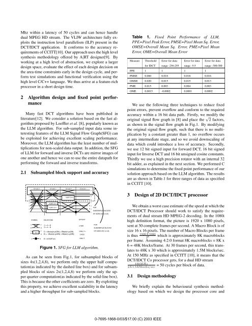
the LLM algorithm. For sub-sampled input data some interesting<br />
features <strong>of</strong> the LLM Signal Flow Graph(SFG) can<br />
be exploited for achieving excellent scaling performance.<br />
Moreover, the LLM algorithm has the least number <strong>of</strong> multiplications<br />
for non-scaled data output. In addition, the SFG<br />
<strong>of</strong> LLM for forward and inverse <strong>DCT</strong>s are mirror images <strong>of</strong><br />
one another and hence we can re-use the entire datapath for<br />
performing the forward and inverse transforms.<br />
2.1 Subsampled block support and accuracy<br />
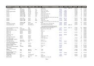
Table 1. Fixed Point Performance <strong>of</strong> LLM,<br />
PPE=Pixel Peak Error, PMSE=Pixel Mean Sq. Error,<br />
OMSE=Overall Mean Sq. Error, PME=Pixel Mean<br />
Error, OME=Overall Mean Error<br />
Measure Threshold Error for data Error for data Error for data<br />
for I<strong>DCT</strong> range -256:255 range -5:5 range -300:300<br />
PPE 1 1 1 1<br />
PMSE 0.060 0.018 0.018 0.016<br />
OMSE 0.020 0.015 0.015 0.013<br />
PME 0.015 0.003 0.004 0.003<br />
OME 0.0015 -0.0002 0.0001 0.0002<br />
We use the following three techniques to reduce fixed<br />
point errors, prevent overflow and conform to the required<br />
accuracy within a 16 bit data path. Firstly, we modify the<br />
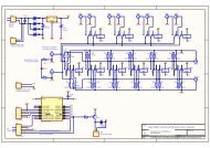
original signal flow graph in [8] and place the √ 2 factors,<br />
as shown in the signal flow graph in Fig.1. By modifying<br />
the original signal flow graph, such that there is no multiplication<br />
by a constant greater than 1, no overflow occurs<br />
at any intermediate stage, and so we avoid downscaling <strong>of</strong><br />
data which could introduce a loss <strong>of</strong> accuracy. Secondly,<br />
we use 12 bit signed input for forward <strong>DCT</strong>, 16 bit signed<br />
input for Inverse <strong>DCT</strong> and 16 bit unsigned cosine constants.<br />
Thirdly we use a high precision rotator with an internal 32<br />
bit adder, as explained in the next section. We performed C<br />
simulations to determine the fixed point performance <strong>of</strong> our<br />
solution approach based on the LLM algorithm. The results<br />
are as shown in Table.1 for three ranges <strong>of</strong> data as specified<br />
in CCITT [10].<br />
0<br />
1<br />
2<br />
3<br />
STAGE 1 STAGE 2 STAGE 3 STAGE 4<br />
SQRT(2)C6<br />
0<br />
4<br />
2<br />
6<br />
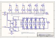
3 <strong>Design</strong> <strong>of</strong> <strong>2D</strong> <strong>DCT</strong>/I<strong>DCT</strong> processor<br />
4<br />
5<br />
6<br />
7<br />
A<br />
B<br />
A<br />
B<br />
SYMBOL<br />
A<br />
kcn<br />
B<br />
EQUATIONS<br />
SQRT(2)C3<br />
SQRT(2)C1<br />
C C = A + B<br />
D<br />
D = A − B<br />
C<br />
C = Akcos(n pi/2N) + Bksin(n pi/2N)<br />
D D = −Aksin(n pi/2N) + Bksin(n pi/2N)<br />
B = A/(SQRT(2))<br />
EFFORT<br />
2 ADD<br />
3 MULT +<br />
3 ADD<br />
1 MULT<br />
Figure 1. SFG for LLM algorithm.<br />
7<br />
3<br />
5<br />
1<br />
FOR<br />
SUBSAMPLED BLOCKS<br />
OF SIZES 4X{1,2,4,8}<br />
FOR<br />
SUBSAMPLED BLOCKS<br />
OF SIZES 2X{1,2,4,8}<br />
As can be seen from Fig.1, for subsampled blocks <strong>of</strong><br />
sizes 4x(1,2,4,8), we perform only the upper half computation(as<br />
indicated by the dashed line box) and for subsampled<br />
blocks <strong>of</strong> sizes 2x(1,2,4,8) we perform only the upper<br />
quarter computation(as indicated by the solid-line box).<br />
This is because the other coefficients are zero. By exploiting<br />
this property, we achieve excellent scalability in the latency<br />
and a higher throughput for sub-sampled blocks.<br />
We obtain a worst case estimate <strong>of</strong> the speed at which the<br />
<strong>DCT</strong>/I<strong>DCT</strong> <strong>Processor</strong> should work to satisfy the requirements<br />
<strong>of</strong> dual stream HD MPEG-2 decoding. In the 1080i<br />
high definition format, the picture is 1920 x 1080 pixels,<br />
sent at 30 complete frames per second. A Macro Block is <strong>of</strong><br />
size 16 x 16 pixels. The number <strong>of</strong> Macro Blocks per frame<br />
is thus 1920X1080<br />
2<br />
which is approximately 8K macroblocks<br />
8<br />
per frame. Assuming 4:2:0 format 8K macroblocks = 8K x<br />
6 = 48K blocks/frame. At 30 frames per second, this translates<br />
to 48K x 30 which is approximately 1.5M blocks/sec.<br />
At 150 MHz as specified in CCITT [10], it means that the<br />
<strong>DCT</strong>/I<strong>DCT</strong> Co processor gets, for a dual HD stream<br />
= 50 cycles per block <strong>of</strong> data.<br />
150MHz<br />
2X1.5Mblocks/sec<br />
3.1 <strong>Design</strong> methodology<br />
We briefly explain the behavioural synthesis methodology<br />
based on which we design the processor core and<br />
0-7695-1868-0/03/$17.00 (C) 2003 IEEE