Design of a 2D DCT/IDCT Application Specific VLIW Processor ...
Design of a 2D DCT/IDCT Application Specific VLIW Processor ...
Design of a 2D DCT/IDCT Application Specific VLIW Processor ...

You also want an ePaper? Increase the reach of your titles
YUMPU automatically turns print PDFs into web optimized ePapers that Google loves.
<strong>Design</strong> <strong>of</strong> a <strong>2D</strong> <strong>DCT</strong>/I<strong>DCT</strong> application specific <strong>VLIW</strong> processor supporting<br />
scaled and sub-sampled blocks<br />
Rohini Krishnan, O.P.Gangwal, Jos.v.Eijndhoven,<br />
Philips Research Laboratories,<br />
Eindhoven, The Netherlands.<br />
Email : rohini.krishnan@philips.com.<br />
Anshul Kumar,<br />
Dept. Of Computer Science,<br />
Indian Institute Of Technology,<br />
New Delhi.<br />
Abstract<br />
We present an innovative design <strong>of</strong> an accurate, <strong>2D</strong> <strong>DCT</strong><br />
I<strong>DCT</strong> processor, which handles scaled and sub-sampled input<br />
blocks efficiently. In the I<strong>DCT</strong> mode, the latency <strong>of</strong> the<br />
processor scales with the size <strong>of</strong> the input blocks varying<br />
from 7 cycles for an 1x1 block to 38 cycles for an 8x8 block.<br />
This scalability is possible because the processor has input<br />
data dependant control by which it can exploit the reduced<br />
computational needs <strong>of</strong> sub-sampled blocks and blocks <strong>of</strong><br />
smaller sizes to work in lesser cycles. This is a very useful<br />
feature for MPEG and HDTV decoders and has hitherto not<br />
been exploited. Clocking at 150 Mhz, the processor satisfies<br />
the high sample rate requirement <strong>of</strong> dual MPEG stream HD<br />
decoding with a picture size <strong>of</strong> 1920 x 1080 at 30 frames per<br />
second. Fixed word length and accuracy simulations <strong>of</strong> our<br />
design shows that it conforms to the accuracy specifications<br />
<strong>of</strong> the CCITT standard within a 16 bit data path.<br />
A methodology based on architecture level synthesis is<br />
used to design the <strong>VLIW</strong> processor core. The <strong>VLIW</strong> design<br />
exploits the Instruction Level Parallelism present in the<br />
<strong>DCT</strong>/I<strong>DCT</strong> application, efficiently. The processor core is<br />
characterised by an area <strong>of</strong> 0.834 mm sq. and a frequency<br />
<strong>of</strong> 150 Mhz in 0.18 micron CMOS technology.<br />
1 Introduction<br />
The Discrete Cosine Transform (<strong>DCT</strong>) is a compute<br />
intensive part <strong>of</strong> the encoders and decoders <strong>of</strong> JPEG,<br />
MPEG, digital HDTV etc. In the past, several architectures<br />
for <strong>DCT</strong>/I<strong>DCT</strong> processors for various application domains<br />
based on different algorithms have been proposed<br />
[12]. All the previous architectures have been optimised<br />
for either performing I<strong>DCT</strong> on fixed 8x8 blocks [1] typically<br />
used in decoders (MPEG, JPEG etc.), or performing<br />
both F<strong>DCT</strong> and I<strong>DCT</strong> on fixed 8x8 blocks [2]-[6]. None <strong>of</strong><br />
these processors are capable <strong>of</strong> exploiting the reduced computational<br />
needs <strong>of</strong> scaled or sub-sampled blocks to give a<br />
higher throughput. Almost all the hitherto published architectures<br />
have a fixed latency for all blocks. Paek et al [7]<br />
support a dual mode <strong>of</strong> operating on 8x8 blocks or 2x4x8<br />
blocks for the digital VCR domain, thus providing support<br />
for scaled blocks <strong>of</strong> size 4x8. In our work, we go a step further<br />
by providing full support for scaled and sub-sampled<br />
blocks <strong>of</strong> sizes (1,2,4,8)x(1,2,4,8). Furthermore, the fixed<br />
point accuracy <strong>of</strong> our design meets the specifications <strong>of</strong> the<br />
CCITT[10] which is more stringent than that <strong>of</strong> the digital<br />
VCR domain.<br />
Scaled blocks (<strong>of</strong> sizes less than 8x8) can arise in MPEG-<br />
2 decoders. For instance, the output <strong>of</strong> the inverse quantiser<br />
in a MPEG-2 decoder, can have many rows with zero<br />
valued coefficients. This output serves as an input to the<br />
inverse <strong>DCT</strong> processor. Instead <strong>of</strong> communicating the the<br />
zero valued rows, only the non-zero rows can be communicated<br />
from the output <strong>of</strong> the inverse quantiser to the inverse<br />
<strong>DCT</strong> processor. This would not only reduce the communication<br />
between the inverse quantiser and the inverse<br />
<strong>DCT</strong> processor but also speed up the decoding due to the<br />
reduced computational requirements. Sub-sampled blocks<br />
are those in which components <strong>of</strong> certain frequencies are<br />
omitted. Sub-sampled blocks can arise, for example, due to<br />
Picture In Picture requirements <strong>of</strong> HDTV where one picture<br />
is displayed inside another, at the cost <strong>of</strong> a reduced resolution<br />
<strong>of</strong> one. Another application where sub-sampled blocks<br />
can arise is in High Definition to Standard Definition downconversion.<br />
The speed up in decoding can only be achieved<br />
if the inverse <strong>DCT</strong> processor is capable <strong>of</strong> working at a reduced<br />
latency for scaled and sub-sampled blocks.<br />
In summary, the proposed architecture can perform<br />
F<strong>DCT</strong> and I<strong>DCT</strong> and in the I<strong>DCT</strong> mode support subsampled<br />
and scaled blocks. It is area-efficient and uses a<br />
common 16 bit data path for performing both F<strong>DCT</strong> and<br />
I<strong>DCT</strong>. It shows excellent scaling in its performance by having<br />
a higher throughput for sub-sampled and scaled blocks.<br />
The latency <strong>of</strong> the processor varies from 7 cycles to 38 cycles,<br />
depending on the input block size. It works at 150<br />
0-7695-1868-0/03/$17.00 (C) 2003 IEEE
Mhz within a latency <strong>of</strong> 50 cycles and can hence handle<br />
dual MPEG HD stream. The <strong>VLIW</strong> architecture fully exploits<br />
the instruction level parallelism (ILP) present in the<br />
<strong>DCT</strong>/I<strong>DCT</strong> application. It conforms to the accuracy requirements<br />
<strong>of</strong> CCITT[10]. Our approach uses the high level<br />
synthesis methodology <strong>of</strong>fered by A|RT designer[9]. By<br />
working at a high level <strong>of</strong> abstraction, we explore a larger<br />
design space, evaluate the effect <strong>of</strong> each design decision on<br />
the area-time constraints early in the design cycle, and perform<br />
test simulations and functional verification using the<br />
high level C/C++ language. We thus arrive at a feature-rich<br />
processor in a short design time.<br />
2 Algorithm design and fixed point performance<br />
Many fast <strong>DCT</strong> algorithms have been published in<br />
literature[12]. We consider a solution based on the fast algorithm<br />
proposed by Loeffler et al. [8], popularly known as<br />
the LLM algorithm. For sub-sampled input data some interesting<br />
features <strong>of</strong> the LLM Signal Flow Graph(SFG) can<br />
be exploited for achieving excellent scaling performance.<br />
Moreover, the LLM algorithm has the least number <strong>of</strong> multiplications<br />
for non-scaled data output. In addition, the SFG<br />
<strong>of</strong> LLM for forward and inverse <strong>DCT</strong>s are mirror images <strong>of</strong><br />
one another and hence we can re-use the entire datapath for<br />
performing the forward and inverse transforms.<br />
2.1 Subsampled block support and accuracy<br />
Table 1. Fixed Point Performance <strong>of</strong> LLM,<br />
PPE=Pixel Peak Error, PMSE=Pixel Mean Sq. Error,<br />
OMSE=Overall Mean Sq. Error, PME=Pixel Mean<br />
Error, OME=Overall Mean Error<br />
Measure Threshold Error for data Error for data Error for data<br />
for I<strong>DCT</strong> range -256:255 range -5:5 range -300:300<br />
PPE 1 1 1 1<br />
PMSE 0.060 0.018 0.018 0.016<br />
OMSE 0.020 0.015 0.015 0.013<br />
PME 0.015 0.003 0.004 0.003<br />
OME 0.0015 -0.0002 0.0001 0.0002<br />
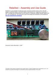
We use the following three techniques to reduce fixed<br />
point errors, prevent overflow and conform to the required<br />
accuracy within a 16 bit data path. Firstly, we modify the<br />
original signal flow graph in [8] and place the √ 2 factors,<br />
as shown in the signal flow graph in Fig.1. By modifying<br />
the original signal flow graph, such that there is no multiplication<br />
by a constant greater than 1, no overflow occurs<br />
at any intermediate stage, and so we avoid downscaling <strong>of</strong><br />
data which could introduce a loss <strong>of</strong> accuracy. Secondly,<br />
we use 12 bit signed input for forward <strong>DCT</strong>, 16 bit signed<br />
input for Inverse <strong>DCT</strong> and 16 bit unsigned cosine constants.<br />
Thirdly we use a high precision rotator with an internal 32<br />
bit adder, as explained in the next section. We performed C<br />
simulations to determine the fixed point performance <strong>of</strong> our<br />
solution approach based on the LLM algorithm. The results<br />
are as shown in Table.1 for three ranges <strong>of</strong> data as specified<br />
in CCITT [10].<br />
0<br />
1<br />
2<br />
3<br />
STAGE 1 STAGE 2 STAGE 3 STAGE 4<br />
SQRT(2)C6<br />
0<br />
4<br />
2<br />
6<br />
3 <strong>Design</strong> <strong>of</strong> <strong>2D</strong> <strong>DCT</strong>/I<strong>DCT</strong> processor<br />
4<br />
5<br />
6<br />
7<br />
A<br />
B<br />
A<br />
B<br />
SYMBOL<br />
A<br />
kcn<br />
B<br />
EQUATIONS<br />
SQRT(2)C3<br />
SQRT(2)C1<br />
C C = A + B<br />
D<br />
D = A − B<br />
C<br />
C = Akcos(n pi/2N) + Bksin(n pi/2N)<br />
D D = −Aksin(n pi/2N) + Bksin(n pi/2N)<br />
B = A/(SQRT(2))<br />
EFFORT<br />
2 ADD<br />
3 MULT +<br />
3 ADD<br />
1 MULT<br />
Figure 1. SFG for LLM algorithm.<br />
7<br />
3<br />
5<br />
1<br />
FOR<br />
SUBSAMPLED BLOCKS<br />
OF SIZES 4X{1,2,4,8}<br />
FOR<br />
SUBSAMPLED BLOCKS<br />
OF SIZES 2X{1,2,4,8}<br />
As can be seen from Fig.1, for subsampled blocks <strong>of</strong><br />
sizes 4x(1,2,4,8), we perform only the upper half computation(as<br />
indicated by the dashed line box) and for subsampled<br />
blocks <strong>of</strong> sizes 2x(1,2,4,8) we perform only the upper<br />
quarter computation(as indicated by the solid-line box).<br />
This is because the other coefficients are zero. By exploiting<br />
this property, we achieve excellent scalability in the latency<br />
and a higher throughput for sub-sampled blocks.<br />
We obtain a worst case estimate <strong>of</strong> the speed at which the<br />
<strong>DCT</strong>/I<strong>DCT</strong> <strong>Processor</strong> should work to satisfy the requirements<br />
<strong>of</strong> dual stream HD MPEG-2 decoding. In the 1080i<br />
high definition format, the picture is 1920 x 1080 pixels,<br />
sent at 30 complete frames per second. A Macro Block is <strong>of</strong><br />
size 16 x 16 pixels. The number <strong>of</strong> Macro Blocks per frame<br />
is thus 1920X1080<br />
2<br />
which is approximately 8K macroblocks<br />
8<br />
per frame. Assuming 4:2:0 format 8K macroblocks = 8K x<br />
6 = 48K blocks/frame. At 30 frames per second, this translates<br />
to 48K x 30 which is approximately 1.5M blocks/sec.<br />
At 150 MHz as specified in CCITT [10], it means that the<br />
<strong>DCT</strong>/I<strong>DCT</strong> Co processor gets, for a dual HD stream<br />
= 50 cycles per block <strong>of</strong> data.<br />
150MHz<br />
2X1.5Mblocks/sec<br />
3.1 <strong>Design</strong> methodology<br />
We briefly explain the behavioural synthesis methodology<br />
based on which we design the processor core and<br />
0-7695-1868-0/03/$17.00 (C) 2003 IEEE
achieve the support for scaled and sub-sampled blocks. The<br />
A|RT <strong>Design</strong>er tool [9], which we use for the design <strong>of</strong> our<br />
processor core, takes as input the behavioural description<br />
<strong>of</strong> the algorithm in a subset <strong>of</strong> C, and generates a RT level<br />
synthesisable HDL model <strong>of</strong> the application specific<strong>VLIW</strong><br />
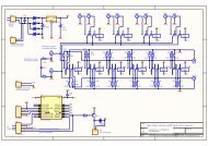
processor. The classical design flow steps begins with the<br />
compilation <strong>of</strong> the source code inclusive <strong>of</strong> identifying and<br />
accurately representing the parallelism present in the source<br />
program. This is followed by creation <strong>of</strong> an architecture and<br />
mapping the source code data flow to the architecture. Removal<br />
<strong>of</strong> redundant hardware, scheduling <strong>of</strong> the operations<br />
and finally generating the microcode control ROM and RT<br />
level synthesisable HDL model completes the design flow<br />
steps shown in Fig.2.<br />
C<br />
DEFAULT<br />
LIBRARY<br />
USER<br />
LIBRARY<br />
PRAGMA<br />
A<br />
32<br />
MULTIPLY<br />
COS(N)<br />
16<br />
ROUND ADD<br />
B<br />
MULTIPLY<br />
16<br />
SIN(N)<br />
−B<br />
32<br />
32<br />
MULTIPLY<br />
COS(N)<br />
16<br />
ROUND ADD<br />
A<br />
MULTIPLY<br />
16<br />
SIN(N)<br />
32<br />
LOW PRECISION(LP) ROTATORS<br />
C<br />
16<br />
D<br />
16<br />
A<br />
MULTIPLY<br />
32<br />
COS(N)<br />
B<br />
ADD<br />
32<br />
ROUND<br />
C<br />
16<br />
MULTIPLY<br />
SIN(N)<br />
−B<br />
32<br />
32<br />
MULTIPLY<br />
COS(N)<br />
ADD<br />
32<br />
ROUND<br />
D<br />
A<br />
16<br />
MULTIPLY<br />
SIN(N)<br />
32<br />
HIGH PRECISION(HP) ROTATORS<br />
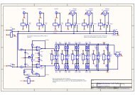
Figure 3. Block diagram <strong>of</strong> LP and HP rotators.<br />
Table 2. Fixed Point Performance for F<strong>DCT</strong> with HP<br />
and LP rotator.<br />
Measure Data range Data range Data range<br />
(-256:255) (-5:5) (-300:300)<br />
HP, LP HP, LP HP, LP<br />
PPE 1, 1 1, 1 1, 1<br />
EDIT/COMPILE<br />
SOURCE<br />
CREATE<br />
ARCHITECTURE<br />
MAP TO<br />
ARCHITECTURE<br />
SCHEDULE<br />
OPERATIONS<br />
PMSE 0.126, 0.146 0.122, 0.148 0.124, 0.149<br />
OMSE 0.101, 0.114 0.100, 0.119 0.101, 0.122<br />
PRAGMA<br />
PRAGMA<br />
PRAGMA<br />
BUILD RT<br />
LEVEL<br />
VHDL<br />
VERILOG<br />
CYCLE<br />
TRUE C<br />
PME 0.009, 0.012 0.009, 0.013 0.009, 0.010<br />
OME 0.0006, 0.0001 0.0002, 0.0002 0.0004, 0.0007<br />
Figure 2. A|RT design flow steps.<br />
In addition to the default library present in the tool<br />
framework (consisting <strong>of</strong> ALU, MAC, Multiplier etc), the<br />
designer can describe a custom library, where the resource<br />
can be modelled as a black box with only the time shape<br />
<strong>of</strong> the inputs and outputs described. The detailed HDL or<br />
cycle true C model <strong>of</strong> the custom components needs to be<br />
provided only before the RT model <strong>of</strong> the processor is built.<br />
The mapping <strong>of</strong> the operations to the type <strong>of</strong> functional unit<br />
is done by the designer during the mapping to architecture<br />
phase. The schedule step generates the total cycle count<br />
for the particular combination <strong>of</strong> resources and mapping.<br />
The A|RT tool generates the <strong>VLIW</strong> controller (consisting<br />
<strong>of</strong> micro code ROM, status and branch logic blocks, program<br />
counter), register files and multiplexers. The inputs<br />
<strong>of</strong> the controller are the status flags generated in the data<br />
path as well as a reset, initialise, and start up signal generated<br />
by the external hardware. The controller uses them to<br />
determine which instructions to execute next.<br />
3.2 <strong>Design</strong> <strong>of</strong> computational core<br />
The butterfly operation in Fig.1 translates to two additions<br />
in terms <strong>of</strong> effort. The butterfly is modelled as a single<br />
cycle resource. It takes two 16 bits normalised signed inputs<br />
and produces two 16 bits normalised signed outputs,<br />
one being the sum <strong>of</strong> the two inputs, the other being the<br />
difference.<br />
The rotation operation is a dual output one. It is implemented<br />
using two single output resources as shown in Fig.3.<br />
The rotator is a two cycle pipelined resource. It consists <strong>of</strong><br />
a multiplication followed by an addition and rounding stage<br />
as shown in Fig.3. The rotator can be designed as a high<br />
precision (HP) rotator or a low precision (LP) rotator. The<br />
low precision version, has a multiplication stage followed<br />
by rounding and 16 bit addition. The high precision version,<br />
has a multiplication stage followed by 32 bit addition<br />
and rounding.<br />
Table.2 shows the improved accuracy achieved in HP rotator<br />
by rounding after the 32 bit addition and thereby reducing<br />
the frequency <strong>of</strong> the last bit in error. Table.2 only<br />
shows the fixed point simulations for the forward <strong>DCT</strong>,<br />
since the accuracy for inverse <strong>DCT</strong> is acceptable with both<br />
the LP and HP rotators. It can be seen from Table.2 that for<br />
the forward <strong>DCT</strong>, using a LP rotator, the mean square errors<br />
are significantly higher than when a HP rotator is used.<br />
Since the 32 bit output from the adder is rounded by the<br />
rounding unit to produce a 16 bit output, the external interface<br />
remains at 16 bits. If a lower accuracy version can<br />
be tolerated, LP rotators can be used. Throughout this discussion,<br />
when we say rotator, we refer to the single output<br />
resource, as shown in the upper half or lower half <strong>of</strong> the<br />
block diagram for high precision (HP) rotators. So, a rotation<br />
operation is performed by two single output rotators.<br />
Any good logic synthesis tool would produce a compact<br />
multiplier when either <strong>of</strong> the inputs to the multiplier is a<br />
constant (resulting in a hardwired, constant coefficient multiplier)<br />
[11]. In our implementation, we re-use the constants<br />
<strong>of</strong> the same precision for both F<strong>DCT</strong> and I<strong>DCT</strong> and thus<br />
re-use the compact rotator blocks for both the forward and<br />
inverse operations. From the LLM signal flow graph it can<br />
0-7695-1868-0/03/$17.00 (C) 2003 IEEE
e seen that there are 3 Rotation operations, each with a different<br />
constant and 2 multiplications with 1/ √ 2 (which can<br />
be considered as a rotation by 45 degrees with one <strong>of</strong> the<br />
inputs to the rotator being zero).<br />
The Logic Unit (LU) is a single cycle combinational unit<br />
which needs the following inputs<br />
(a) Scale/No Scale<br />
(b) Number <strong>of</strong> rows in input block<br />
(c) Horizontal Scale Factor (HSF)<br />
(d) Vertical Scale Factor (VSF)<br />
(e) Fdct or Idct. The logic unit produces twenty, 1 bit outputs,<br />
in 1 cycle, each output indicating a particular control<br />
condition. The presence <strong>of</strong> the logic unit eliminates the<br />
overhead for control condition checks.<br />
The Round and Saturation unit is a single cycle unit. It<br />
gets eight, 16 bit numbers as inputs. It is a multi mode resource.<br />
In the F<strong>DCT</strong> case, it produces eight, 12 bit rounded<br />
and saturated outputs. In the I<strong>DCT</strong> case, it produces eight,<br />
9 bit rounded and saturated outputs. In the design <strong>of</strong> this<br />
processor all the intermediate values are stored in registers<br />
and the design <strong>of</strong> a transposition memory is avoided.<br />
3.3 Scaled and sub-sampled block support<br />
The scalability in performance is achieved by avoiding<br />
redundant calculations. For eg., bit 2 output <strong>of</strong> the LU indicates<br />
that the input block is vertically subsampled by 2 and<br />
is <strong>of</strong> size 8x4, bit 17 indicates that the input block is scaled<br />
and is <strong>of</strong> size 4x8 etc. In a vertically subsampled block <strong>of</strong><br />
size 8x4, only the even elements are non zero and thus the<br />
odd half <strong>of</strong> the I<strong>DCT</strong> flow graph can be bypassed (in effect<br />
performing a 4 point I<strong>DCT</strong>). In a scaled 4x8 block, we<br />
perform only 4 row-wise and 8 column-wise transforms.<br />
3.4 <strong>Design</strong> space explorations<br />
In the A|RT design methodology, the user has to manually<br />
map the operations to the resources. The number <strong>of</strong> resources<br />
<strong>of</strong> each type also needs to be decided by the user. To<br />
determine the number <strong>of</strong> resources <strong>of</strong> each type a good areatime<br />
trade<strong>of</strong>f point needs to be found. We experimented<br />
with various combinations <strong>of</strong> general purpose and custom<br />
resources. The general purpose resources are available to<br />
the designer in the default library <strong>of</strong> the tool. For the custom<br />
resources, the designer needs to define the time shape<br />
<strong>of</strong> the inputs and the outputs.<br />
General purpose/custom units can be used for performing<br />
the data path operations. For eg., the butterfly consists<br />
<strong>of</strong> one addition and one subtraction operation. It can be<br />
implemented by mapping these operations to the arithmetic<br />
and logic units (ALUs) present in the default library. To perform<br />
the addition and subtraction in parallel, each butterfly<br />
has to be mapped onto two ALUs. This mapping for each<br />
<strong>of</strong> the butterfly operations has to be done manually in A|RT,<br />
which is a bit tricky, since a bad mapping could result in a<br />
bad schedule and cycle overheads. The mapping is much<br />
simpler when we use custom units for the operation, since<br />
there is a direct correspondence between the operation and<br />
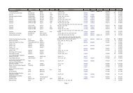
the functionality <strong>of</strong> the custom unit. We evaluated the cycle<br />
and regfile size overhead for each combination <strong>of</strong> general<br />
purpose and custom units. This is illustrated in Fig.4. Ap-<br />
NUMBER OF RESOURCES<br />
CYCLE COUNT<br />
20<br />
18<br />
16<br />
14<br />
12<br />
10<br />
8<br />
6<br />
4<br />
2<br />
65<br />
60<br />
55<br />
50<br />
45<br />
40<br />
35<br />
CUSTOM LOGIC UNIT<br />
ROTATOR ALU (USED FOR ADDITION<br />
AND LOGIC)<br />
01<br />
01<br />
01<br />
01<br />
0<br />
01<br />
01<br />
01<br />
01<br />
ALU(ONLY FOR ADDITION) 01<br />
BUTTERFLY<br />
01<br />
01<br />
01<br />
01<br />
01<br />
01<br />
01<br />
01<br />
01<br />
01<br />
01<br />
01<br />
01<br />
01<br />
01<br />
01<br />
01<br />
01<br />
01<br />
01<br />
01<br />
01<br />
01<br />
01<br />
01<br />
01<br />
01<br />
01<br />
01<br />
01<br />
01<br />
01<br />
01<br />
01<br />
01<br />
01<br />
01<br />
01<br />
01<br />
01<br />
01<br />
01<br />
01<br />
01<br />
01<br />
01<br />
01<br />
01<br />
01<br />
01<br />
01<br />
01<br />
01<br />
01<br />
01<br />
01<br />
01<br />
01<br />
01<br />
01<br />
01<br />
01<br />
01<br />
01<br />
01<br />
01<br />
01<br />
01<br />
01<br />
01<br />
01<br />
01<br />
01<br />
01<br />
01<br />
01<br />
01<br />
01<br />
01<br />
01<br />
01<br />
01<br />
01<br />
01<br />
01<br />
01<br />
01<br />
01<br />
01<br />
01<br />
01<br />
01<br />
01<br />
01<br />
01<br />
01<br />
01<br />
01<br />
01<br />
01<br />
01<br />
01<br />
01<br />
01<br />
01<br />
01<br />
01<br />
01<br />
01<br />
01<br />
01<br />
01<br />
01<br />
01<br />
01<br />
01<br />
01<br />
01<br />
01<br />
01<br />
01<br />
01<br />
01<br />
01<br />
01<br />
01<br />
01<br />
01<br />
01<br />
01<br />
01<br />
01<br />
01<br />
01<br />
01<br />
01<br />
01<br />
01<br />
01<br />
01<br />
01<br />
01<br />
01<br />
01<br />
01<br />
01<br />
01<br />
01<br />
01<br />
01<br />
01<br />
01<br />
01<br />
01<br />
01<br />
01<br />
01<br />
01<br />
01<br />
01<br />
01<br />
01<br />
01<br />
01<br />
01<br />
01<br />
01<br />
01<br />
01<br />
01<br />
01<br />
01<br />
01<br />
01<br />
01<br />
01<br />
01<br />
1 2 3 4 5 6 7 8 9 10 11 12 13<br />
3 4 5 6 7 8 9 10 11 12<br />
1 2 13<br />
COMBINATION USED<br />
1<br />
0 0 1 1<br />
REGFILE SIZE(KBITS)<br />
8<br />
6<br />
4<br />
2<br />
01<br />
01<br />
01<br />
01<br />
01<br />
1<br />
01 0 00 1 11 0 000000 1 111111<br />
COMBINATION USED<br />
01<br />
01<br />
01<br />
01<br />
01<br />
01<br />
01<br />
01<br />
01<br />
01<br />
01<br />
01<br />
01<br />
01<br />
01<br />
01<br />
01<br />
01<br />
01<br />
01<br />
01<br />
01<br />
01<br />
01<br />
01<br />
01<br />
01<br />
01<br />
01<br />
01<br />
01<br />
01<br />
01<br />
01<br />
01<br />
01<br />
01<br />
01<br />
01<br />
01<br />
01<br />
01<br />
01<br />
01<br />
01<br />
01<br />
01<br />
01<br />
01<br />
2 3 4 5 6 7 8 9 10 11 12 13<br />
COMBINATION USED<br />
Figure 4. Cycle Count for various combinations <strong>of</strong><br />
resources.<br />
proach 1 with 20 ALUs, 8 rotators, 1 custom logic unit has<br />
the best cycle count <strong>of</strong> 38, but the area overhead is high.<br />
The register file size is 3.8 kbits. Approach 2 with 10 Butterflies,<br />
8 rotators, 1 custom logic unit has a cycle count <strong>of</strong><br />
41 and a register file size <strong>of</strong> 3 kbits. In Approach 11, we<br />
map the logic operation <strong>of</strong> the control condition check and<br />
addition <strong>of</strong> the butterfly to the same ALU, and observe the<br />
cycle count and register file size. In some <strong>of</strong> the approaches,<br />
we use dedicated ALUs for addition (i.e. logic operations<br />
are not mapped on the same ALU).<br />
We conclude that Approach 2 is promising and provides<br />
the most optimal area-cycle count trade <strong>of</strong>f point. In Fig.4<br />
we do not show the rounding and saturation unit, input and<br />
output ports which are common to all the approaches. We<br />
use 1 rounding and saturation unit and 8 input ports and<br />
8 output ports in all the approaches. We next, experiment<br />
with different kinds <strong>of</strong> input and output ports. In the A|RT<br />
design flow, the designer has an option <strong>of</strong> choosing addressable<br />
or non-addressable ports. The former reads data from<br />
and writes data to a RAM (assuming all the input data is<br />
readily available), while the latter communicates with the<br />
external world through handshake signals [9]. The input<br />
and output ports used for obtaining the cycle count figures<br />
in Fig.4 referred to the addressable variety.<br />
Table.3 shows the cycle count and register file sizes for<br />
input and output ports <strong>of</strong> the non-addressable variety. From<br />
the table it is clear that non-addressable inports and outports<br />
are preferable. The regfile size and cycle counts are larger<br />
when using addressable ports because <strong>of</strong> the overhead in<br />
0-7695-1868-0/03/$17.00 (C) 2003 IEEE
Table 3. Addressable and Non-addressable ports<br />
comparison<br />
Type <strong>of</strong> port Regfile(Kbits) Cycle count<br />
Addressable 3.454 41<br />
Non-addressable 2.872 38<br />
PR = PIPELINE REG<br />
01<br />
01<br />
01<br />
00000<br />
11111 01<br />
01<br />
00000<br />
111110<br />
1<br />
PR 1 PR 2 PR 3 PR 4<br />
READ 01<br />
READ FROM EXTERNAL MEMORY 01<br />
WRITE 01<br />
01<br />
000 111<br />
01<br />
01<br />
INTO PROC<br />
FOR NEXT BLOCK CAN BEGIN HERE<br />
STAGE1 STAGE2 STAGE3 STAGE4<br />
01<br />
01<br />
FROM PROC 01<br />
01<br />
01<br />
01<br />
00000<br />
11111<br />
00000000000000<br />
11111111111111<br />
01<br />
0000 1111 01<br />
01<br />
00000<br />
11111<br />
00000000000000<br />
111111111111110000<br />
00000<br />
11111<br />
00000000000000<br />
11111111111111111<br />
0000<br />
00000<br />
11111<br />
01<br />
00000000000000<br />
11111111111111111<br />
0000<br />
01<br />
01<br />
01<br />
COMPUTE<br />
01<br />
01<br />
00000000000000000000<br />
11111111111111111111<br />
01<br />
01<br />
01<br />
01<br />
38 CYCLES<br />
01<br />
01<br />
000000000000000000000<br />
1111111111111111111110<br />
1<br />
01<br />
READ FROM<br />
READ NEXT BLOCK FROM<br />
EXTERNAL MEMORY EXTERNAL MEMORY<br />
COMPUTATION<br />
COMPUTATION<br />
WRITE TO<br />
EXTERNAL MEMORY<br />
generating the address values for data to be read from the<br />
external RAM.<br />
Table 4. Scheduling algorithms comparison<br />
Type Regfile(Kbits) Cycle count<br />
All 2.872 38<br />
Asap 3.688 43<br />
Alap 2.792 38<br />
Alap Greedy 2.776 38<br />
Table.4 depicts the various scheduling algorithms and<br />
their effects on regfile sizes and cycle counts. Depending<br />
on the scheduling algorithm chosen, the register life time<br />
can vary, and the size <strong>of</strong> the register file can change. For<br />
instance, the table clearly shows that the ASAP scheduling<br />
algorithm increases the register life time in our application.<br />
We choose the ALAP Greedy scheduling algorithm since it<br />
has the best cycle count, regfile file size combination. The<br />
final block diagram <strong>of</strong> the processor is as shown in Fig.5.<br />
ROT1<br />
ROT8<br />
LOGIC<br />
UNIT<br />
BF1<br />
MICRO CODE ROM<br />
BF10<br />
REGISTER FILES<br />
MULTIPLEXERS<br />
ROUND<br />
SAT UNIT<br />
INTERCONNECT NETWORK<br />
Figure 5. Final block diagram<br />
8 INPUT PORTS 8 OUTPUT PORTS<br />
3.5 Pipelining and interfacing to external hardware<br />
The rotator is internally pipelined as explained in section<br />
3.2. The <strong>DCT</strong>/I<strong>DCT</strong> processor has a four stage pipeline as<br />
shown in the left half <strong>of</strong> the Fig.6 where each stage refers<br />
to a stage in the flow graph in Fig.1 and has a latency <strong>of</strong><br />
two. The next block <strong>of</strong> data can be read in only after the<br />
latency as shown in Fig.7. This is because a common data<br />
path has been used for computing the row wise and column<br />
wise transform. The row-wise transform for the next block<br />
Figure 6. Pipelining <strong>of</strong> Read-Compute-Write phases.<br />
cannot begin until the column-wise transform for the previous<br />
block is completed. For example, the data introduction<br />
interval is 26 cycles for an 8x2 subsampled block and 38<br />
cycles for a 8x8 block (Fig.7).<br />
The processor communicates with the external world<br />
through handshake signals [9]. All the cycle counts mentioned<br />
so far indicate the time taken for computing the forward<br />
or inverse <strong>DCT</strong> assuming the input data is available at<br />
the input port as soon as it is needed and the output data can<br />
be drained from the output port as soon as it becomes available.<br />
This is far from true in a realistic situation. If the input<br />
data is not available the processor will stall until it becomes<br />
available [9]. Similarly, if the data at the output ports is not<br />
drained immediately, the processor will stall again [9]. To<br />
reduce the frequency <strong>of</strong> stalls, the input and output data can<br />
be buffered external to the processor. The depth <strong>of</strong> the FIFO<br />
buffers will depend on the external read and write latency.<br />
With the introduction <strong>of</strong> such buffers, the read from external<br />
memory, computation and write to external memory can<br />
work in a pipeline as shown in the right half <strong>of</strong> Fig.6.<br />
4 Results<br />
The <strong>VLIW</strong> F<strong>DCT</strong>/I<strong>DCT</strong> processor shows good scaling<br />
in its performance. This is illustrated in Fig. 7. For example,<br />
the processor works in 24 cycles for a subsampled<br />
block <strong>of</strong> size 4x4, in 18 cycles for 2x4 etc.<br />
4.1 Comparison with previous architectures<br />
Table.5 compares the previous designs after scaling them<br />
to the technology used in the current design. The table<br />
clearly shows that only the proposed design fully supports<br />
scaled and sub-sampled blocks. The delay figures <strong>of</strong> the<br />
proposed design vary from 0.046 to 0.253µs. Thus for subsampled<br />
and scaled blocks, the proposed design is faster<br />
than all the existing architectures. The design proposed in<br />
[6] can be scaled in the sense that it can be adapted for<br />
higher throughput by adding data path units in parallel with<br />
a consequent increase in area. But with a fixed architecture,<br />
it is not scalable. The architecture proposed in [7] is par-<br />
0-7695-1868-0/03/$17.00 (C) 2003 IEEE
44<br />
40<br />
36<br />
32<br />
28<br />
24<br />
20<br />
16<br />
12<br />
8<br />
4<br />
CYCLE<br />
COUNT<br />
NON−SUBSAMPLED BLOCKS<br />
(SCALED BLOCKS)<br />
F<strong>DCT</strong><br />
SUBSAMPLED BLOCKS<br />
1X8<br />
2X8<br />
4X8<br />
8X8<br />
4X8<br />
2X8<br />
1X8<br />
8X4<br />
4X4<br />
2X4<br />
1X4<br />
8X2<br />
4X2<br />
2X2<br />
1X2<br />
8X1<br />
4X1<br />
2X1<br />
1X1<br />
Figure 7. Scaling performance <strong>of</strong> processor.<br />
BLOCK SIZES<br />
tially scalable and is very compact. It can operate on 8x8<br />
blocks or 2x4x8 blocks. Their proposed architecture is optimised<br />
for the digital VCR domain and does not meet the<br />
higher accuracy requirements <strong>of</strong> CCITT. (For e.g., the mean<br />
square error should be ≤ 0.083 for I<strong>DCT</strong> in the digital VCR<br />
domain, whereas the mean square error required by CCITT<br />
is ≤ 0.020.) If the accuracy requirements <strong>of</strong> CCITT need<br />
to be met by the architecture in [7], it would no longer be<br />
as compact. Hence, the proposed architecture is superior in<br />
its higher accuracy and support for sub-sampled and scaled<br />
blocks and <strong>of</strong>fers significant advantages in comparison with<br />
the existing designs.<br />
Table 5. Comparison after scaling to 0.18µ CMOS<br />
technology<br />
Method Latency(cycles) Area(mm 2 Delay = latency/Freq.(µs)<br />
[1] ∗∗ 24 3.57 0.108<br />
[2] ∗ 128 1.0692 0.288<br />
[3] ∗ 135 0.588 0.2209<br />
[5] ∗ 72 5.4 0.216<br />
[7] ∗ 1208(fdct) 0.072 10.98(fdct)<br />
1192(idct)<br />
10.84(fdct)<br />
[8] ∗+ 54-108 0.196 0.1335 (4x8)<br />
0.267(8x8)<br />
Ours ∗++ 7-38 0.834 0.046 - 0.253<br />
∗∗ I<strong>DCT</strong> only<br />
∗ F<strong>DCT</strong> and I<strong>DCT</strong><br />
∗+ F<strong>DCT</strong> and I<strong>DCT</strong> and partial support for scaled blocks<br />
∗++ F<strong>DCT</strong> and I<strong>DCT</strong> and full support for scaled and sub-sampled blocks<br />
5 Conclusion<br />
This paper showed the design <strong>of</strong> a fully scalable<br />
F<strong>DCT</strong>/I<strong>DCT</strong> <strong>VLIW</strong> processor. The core fully satisfies the<br />
accuracy requirements specified in CCITT. The processor<br />
can handle the high speed requirements <strong>of</strong> dual stream HD<br />
decoding. The presence <strong>of</strong> input data dependant control results<br />
in an excellent scaling performance <strong>of</strong> the processor.<br />
Such multi-functional hardware ensures that the processor<br />
can find extensive use in applications where both forward<br />
and inverse <strong>DCT</strong> need to be performed (Eg. where<br />
both encoders and decoders are present locally). The proposed<br />
design <strong>of</strong>fers specific advantages among others, in<br />
MPEG-2 decoders where scaled blocks can arise, in HDTV<br />
decoders where sub-sampled blocks can arise since there is<br />
a need to handle the Picture in Picture(PIP) functionality,<br />
and also in HD to SD down conversion in set top boxes. By<br />
working at a reduced latency for scaled and sub-sampled<br />
blocks, the proposed processor core can speed up MPEG-2<br />
decoding.<br />
The paper also discusses how the effects <strong>of</strong> each design<br />
decision on area and cycle time were analysed to arrive<br />
at the final optimal architecture. The comparison with the<br />
existing architectures shows that the proposed design is<br />
superior and <strong>of</strong>fers many advantages.<br />
References<br />
[1] P.A.Ruetzetal., ”A 160 Mpixels/s I<strong>DCT</strong> processor for<br />
HDTV”, IEEE Micro, pp. 28-32, 1991.<br />
[2] Uramoto et al., ”A 100 Mhz 2-D Discrete Cosine Transform<br />
Core <strong>Processor</strong>”, IEEE Journal <strong>of</strong> Solid State Circuits, Vol.<br />
27, No. 4, pp. 492-499, Apr 1992.<br />
[3] W. Li et al., ”A high speed 2-D <strong>DCT</strong>/I<strong>DCT</strong> processor”,<br />
IEEE Intl. Symposium On Circuits And Systems, Vol. 1, pp.<br />
192-195, 1991.<br />
[4] V. Srinivasan et al., ”VLSI <strong>Design</strong> <strong>of</strong> high speed time recursive<br />
<strong>2D</strong> <strong>DCT</strong>/I<strong>DCT</strong> processor for video applications”, IEEE<br />
Transaction On Circuits And Systems For Video Tech., Vol.<br />
6, No. 1, pp. 87-96, Feb, 1996.<br />
[5] H. Lim et al., ”A Serial Parallel architecture for <strong>2D</strong> <strong>DCT</strong><br />
and I<strong>DCT</strong>”, IEEE Transaction On Computer, Vol. 49, No.<br />
12, pp. 1297-1309, Dec, 2000.<br />
[6] T. Chang et al., ”A simple processor core design for<br />
<strong>DCT</strong>/I<strong>DCT</strong>”, IEEE Transaction On Circuits And Systems<br />
For Video Tech., Vol. 10, No. 3, pp. 439-447, Apr, 2000.<br />
[7] S. K. Paek et al., ”A mode changeable <strong>2D</strong> <strong>DCT</strong>/I<strong>DCT</strong> processor<br />
for digital VCR”, IEEE Transaction On Consumer<br />
Electronics, Vol. 42, No. 3, pp. 606-616, Aug, 1996.<br />
[8] C. Loeffler et al., ”Practical Fast 1-D <strong>DCT</strong> Algorithms with<br />
11 multiplications”, Intl. Conf. On Acoustics, Speech and<br />
Signal Processing, ICASSP, pp. 988-991, May, 1989.<br />
[9] ART <strong>Design</strong>er Reference manual, Frontier <strong>Design</strong>, v2.3<br />
rev15, Apr, 2001. www.adelantetechnologies.com.<br />
[10] CCITT SGXV Working Party XV/1 Specialists Group On<br />
Coding For Visual Telephony, Document 584, Nov., 1989.<br />
[11] K. E. Wires et al. ”Combined Unsigned and Two’s Complement<br />
Squarers”, Proc. <strong>of</strong> the 33 Asilomar Conference on<br />
Signals, Systems, and Computers, Pacific Grove, California,<br />
pp. 1215-1219, Oct, 1999.<br />
[12] K. R. Rao and P. Yip ”Discrete Cosine Transform : algorithms,<br />
advantages, applications”. Academic Press, 1990.<br />
0-7695-1868-0/03/$17.00 (C) 2003 IEEE