Design of a 2D DCT/IDCT Application Specific VLIW Processor ...
Design of a 2D DCT/IDCT Application Specific VLIW Processor ...
Design of a 2D DCT/IDCT Application Specific VLIW Processor ...

You also want an ePaper? Increase the reach of your titles
YUMPU automatically turns print PDFs into web optimized ePapers that Google loves.
e seen that there are 3 Rotation operations, each with a different<br />
constant and 2 multiplications with 1/ √ 2 (which can<br />
be considered as a rotation by 45 degrees with one <strong>of</strong> the<br />
inputs to the rotator being zero).<br />
The Logic Unit (LU) is a single cycle combinational unit<br />
which needs the following inputs<br />
(a) Scale/No Scale<br />
(b) Number <strong>of</strong> rows in input block<br />
(c) Horizontal Scale Factor (HSF)<br />
(d) Vertical Scale Factor (VSF)<br />
(e) Fdct or Idct. The logic unit produces twenty, 1 bit outputs,<br />
in 1 cycle, each output indicating a particular control<br />
condition. The presence <strong>of</strong> the logic unit eliminates the<br />
overhead for control condition checks.<br />
The Round and Saturation unit is a single cycle unit. It<br />
gets eight, 16 bit numbers as inputs. It is a multi mode resource.<br />
In the F<strong>DCT</strong> case, it produces eight, 12 bit rounded<br />
and saturated outputs. In the I<strong>DCT</strong> case, it produces eight,<br />
9 bit rounded and saturated outputs. In the design <strong>of</strong> this<br />
processor all the intermediate values are stored in registers<br />
and the design <strong>of</strong> a transposition memory is avoided.<br />
3.3 Scaled and sub-sampled block support<br />
The scalability in performance is achieved by avoiding<br />
redundant calculations. For eg., bit 2 output <strong>of</strong> the LU indicates<br />
that the input block is vertically subsampled by 2 and<br />
is <strong>of</strong> size 8x4, bit 17 indicates that the input block is scaled<br />
and is <strong>of</strong> size 4x8 etc. In a vertically subsampled block <strong>of</strong><br />
size 8x4, only the even elements are non zero and thus the<br />
odd half <strong>of</strong> the I<strong>DCT</strong> flow graph can be bypassed (in effect<br />
performing a 4 point I<strong>DCT</strong>). In a scaled 4x8 block, we<br />
perform only 4 row-wise and 8 column-wise transforms.<br />
3.4 <strong>Design</strong> space explorations<br />
In the A|RT design methodology, the user has to manually<br />
map the operations to the resources. The number <strong>of</strong> resources<br />
<strong>of</strong> each type also needs to be decided by the user. To<br />
determine the number <strong>of</strong> resources <strong>of</strong> each type a good areatime<br />
trade<strong>of</strong>f point needs to be found. We experimented<br />
with various combinations <strong>of</strong> general purpose and custom<br />
resources. The general purpose resources are available to<br />
the designer in the default library <strong>of</strong> the tool. For the custom<br />
resources, the designer needs to define the time shape<br />
<strong>of</strong> the inputs and the outputs.<br />
General purpose/custom units can be used for performing<br />
the data path operations. For eg., the butterfly consists<br />
<strong>of</strong> one addition and one subtraction operation. It can be<br />
implemented by mapping these operations to the arithmetic<br />
and logic units (ALUs) present in the default library. To perform<br />
the addition and subtraction in parallel, each butterfly<br />
has to be mapped onto two ALUs. This mapping for each<br />
<strong>of</strong> the butterfly operations has to be done manually in A|RT,<br />
which is a bit tricky, since a bad mapping could result in a<br />
bad schedule and cycle overheads. The mapping is much<br />
simpler when we use custom units for the operation, since<br />
there is a direct correspondence between the operation and<br />
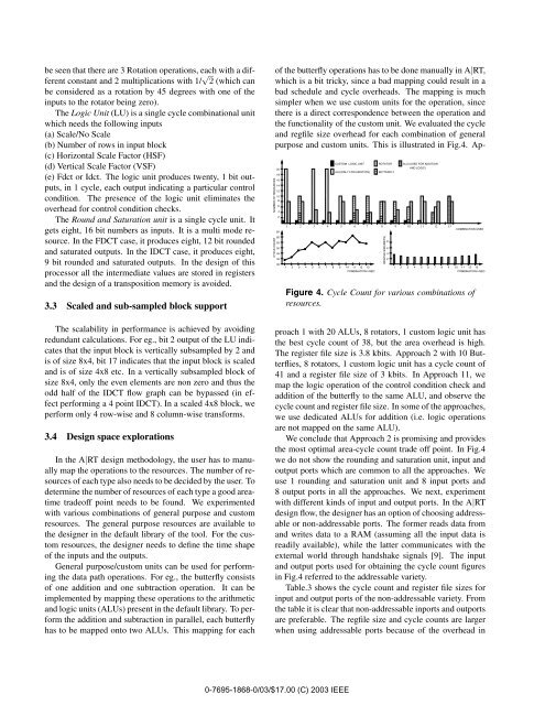
the functionality <strong>of</strong> the custom unit. We evaluated the cycle<br />
and regfile size overhead for each combination <strong>of</strong> general<br />
purpose and custom units. This is illustrated in Fig.4. Ap-<br />
NUMBER OF RESOURCES<br />
CYCLE COUNT<br />
20<br />
18<br />
16<br />
14<br />
12<br />
10<br />
8<br />
6<br />
4<br />
2<br />
65<br />
60<br />
55<br />
50<br />
45<br />
40<br />
35<br />
CUSTOM LOGIC UNIT<br />
ROTATOR ALU (USED FOR ADDITION<br />
AND LOGIC)<br />
01<br />
01<br />
01<br />
01<br />
0<br />
01<br />
01<br />
01<br />
01<br />
ALU(ONLY FOR ADDITION) 01<br />
BUTTERFLY<br />
01<br />
01<br />
01<br />
01<br />
01<br />
01<br />
01<br />
01<br />
01<br />
01<br />
01<br />
01<br />
01<br />
01<br />
01<br />
01<br />
01<br />
01<br />
01<br />
01<br />
01<br />
01<br />
01<br />
01<br />
01<br />
01<br />
01<br />
01<br />
01<br />
01<br />
01<br />
01<br />
01<br />
01<br />
01<br />
01<br />
01<br />
01<br />
01<br />
01<br />
01<br />
01<br />
01<br />
01<br />
01<br />
01<br />
01<br />
01<br />
01<br />
01<br />
01<br />
01<br />
01<br />
01<br />
01<br />
01<br />
01<br />
01<br />
01<br />
01<br />
01<br />
01<br />
01<br />
01<br />
01<br />
01<br />
01<br />
01<br />
01<br />
01<br />
01<br />
01<br />
01<br />
01<br />
01<br />
01<br />
01<br />
01<br />
01<br />
01<br />
01<br />
01<br />
01<br />
01<br />
01<br />
01<br />
01<br />
01<br />
01<br />
01<br />
01<br />
01<br />
01<br />
01<br />
01<br />
01<br />
01<br />
01<br />
01<br />
01<br />
01<br />
01<br />
01<br />
01<br />
01<br />
01<br />
01<br />
01<br />
01<br />
01<br />
01<br />
01<br />
01<br />
01<br />
01<br />
01<br />
01<br />
01<br />
01<br />
01<br />
01<br />
01<br />
01<br />
01<br />
01<br />
01<br />
01<br />
01<br />
01<br />
01<br />
01<br />
01<br />
01<br />
01<br />
01<br />
01<br />
01<br />
01<br />
01<br />
01<br />
01<br />
01<br />
01<br />
01<br />
01<br />
01<br />
01<br />
01<br />
01<br />
01<br />
01<br />
01<br />
01<br />
01<br />
01<br />
01<br />
01<br />
01<br />
01<br />
01<br />
01<br />
01<br />
01<br />
01<br />
01<br />
01<br />
01<br />
01<br />
01<br />
01<br />
01<br />
01<br />
01<br />
01<br />
01<br />
01<br />
01<br />
1 2 3 4 5 6 7 8 9 10 11 12 13<br />
3 4 5 6 7 8 9 10 11 12<br />
1 2 13<br />
COMBINATION USED<br />
1<br />
0 0 1 1<br />
REGFILE SIZE(KBITS)<br />
8<br />
6<br />
4<br />
2<br />
01<br />
01<br />
01<br />
01<br />
01<br />
1<br />
01 0 00 1 11 0 000000 1 111111<br />
COMBINATION USED<br />
01<br />
01<br />
01<br />
01<br />
01<br />
01<br />
01<br />
01<br />
01<br />
01<br />
01<br />
01<br />
01<br />
01<br />
01<br />
01<br />
01<br />
01<br />
01<br />
01<br />
01<br />
01<br />
01<br />
01<br />
01<br />
01<br />
01<br />
01<br />
01<br />
01<br />
01<br />
01<br />
01<br />
01<br />
01<br />
01<br />
01<br />
01<br />
01<br />
01<br />
01<br />
01<br />
01<br />
01<br />
01<br />
01<br />
01<br />
01<br />
01<br />
2 3 4 5 6 7 8 9 10 11 12 13<br />
COMBINATION USED<br />
Figure 4. Cycle Count for various combinations <strong>of</strong><br />
resources.<br />
proach 1 with 20 ALUs, 8 rotators, 1 custom logic unit has<br />
the best cycle count <strong>of</strong> 38, but the area overhead is high.<br />
The register file size is 3.8 kbits. Approach 2 with 10 Butterflies,<br />
8 rotators, 1 custom logic unit has a cycle count <strong>of</strong><br />
41 and a register file size <strong>of</strong> 3 kbits. In Approach 11, we<br />
map the logic operation <strong>of</strong> the control condition check and<br />
addition <strong>of</strong> the butterfly to the same ALU, and observe the<br />
cycle count and register file size. In some <strong>of</strong> the approaches,<br />
we use dedicated ALUs for addition (i.e. logic operations<br />
are not mapped on the same ALU).<br />
We conclude that Approach 2 is promising and provides<br />
the most optimal area-cycle count trade <strong>of</strong>f point. In Fig.4<br />
we do not show the rounding and saturation unit, input and<br />
output ports which are common to all the approaches. We<br />
use 1 rounding and saturation unit and 8 input ports and<br />
8 output ports in all the approaches. We next, experiment<br />
with different kinds <strong>of</strong> input and output ports. In the A|RT<br />
design flow, the designer has an option <strong>of</strong> choosing addressable<br />
or non-addressable ports. The former reads data from<br />
and writes data to a RAM (assuming all the input data is<br />
readily available), while the latter communicates with the<br />
external world through handshake signals [9]. The input<br />
and output ports used for obtaining the cycle count figures<br />
in Fig.4 referred to the addressable variety.<br />
Table.3 shows the cycle count and register file sizes for<br />
input and output ports <strong>of</strong> the non-addressable variety. From<br />
the table it is clear that non-addressable inports and outports<br />
are preferable. The regfile size and cycle counts are larger<br />
when using addressable ports because <strong>of</strong> the overhead in<br />
0-7695-1868-0/03/$17.00 (C) 2003 IEEE