HP E-MSM430, E-MSM460, and E-MSM466 Access Points - Etilize
HP E-MSM430, E-MSM460, and E-MSM466 Access Points - Etilize
HP E-MSM430, E-MSM460, and E-MSM466 Access Points - Etilize

Create successful ePaper yourself
Turn your PDF publications into a flip-book with our unique Google optimized e-Paper software.
The E-<strong>MSM430</strong>, E-<strong>MSM460</strong>, <strong>and</strong> E-<strong>MSM466</strong> are Wi-Fi Alliance<br />
authorized Wi-Fi CERTIFIED 802.11n/a/b/g products. The Wi-Fi<br />
CERTIFIED Logo is a certification mark of the Wi-Fi Alliance.<br />
E-<strong>MSM430</strong>, E-<strong>MSM460</strong>, <strong>and</strong> E-<strong>MSM466</strong> 802.11n <strong>Access</strong> <strong>Points</strong> Quickstart<br />
This Quickstart shows you how to install <strong>and</strong> get started using the E-<strong>MSM430</strong>, E-<strong>MSM460</strong>, <strong>and</strong> E-<strong>MSM466</strong> Dual Radio 802.11n <strong>Access</strong> <strong>Points</strong>, hereafter referred<br />
to as the AP except for where specific model references are made. (See Products list on page 8 for part numbers.)<br />
Please visit www.hp.com/networking/support for the latest documentation including the MSM3xx / MSM4xx <strong>Access</strong> <strong>Points</strong> Management <strong>and</strong> Configuration Guide<br />
<strong>and</strong> the MSM7xx Controllers Management <strong>and</strong> Configuration Guide.<br />
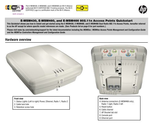
Hardware overview<br />
Front view<br />
1: Status Lights (Left to right) Power, Ethernet, Radio 1, Radio 2<br />
2: Cable lock hole<br />
3: Retention screw hole<br />
➀<br />
➂<br />
➁<br />
In<br />
➆<br />
➆<br />
➃<br />
➇ ➈<br />
➄<br />
➅<br />
➃<br />
Back view<br />
4: Antenna connectors (E-<strong>MSM466</strong> only), �<br />
Radio 1 right, Radio 2 left<br />
5: Reset button<br />
6: Cable channel<br />
7: AP Bracket tab slot<br />
8: Console port<br />
9: Ethernet port<br />
➆<br />
➆
<strong>HP</strong> E-<strong>MSM430</strong>, E-<strong>MSM460</strong>, E-<strong>MSM466</strong> Dual Radio 802.11n <strong>Access</strong> <strong>Points</strong> Quickstart 2 Important information to read before installing<br />
Package contents<br />
The AP, AP Bracket, Padlock Bracket, two sets of AP Bracket T-bar clips with<br />
screws, two mounting screws with wall anchors, retention screw (4-40x1/4”),<br />
Adapter Bracket, <strong>and</strong> documentation.<br />
Ports<br />
• Ethernet port: Auto-sensing 10/100/1000 BaseT Ethernet port with RJ-45<br />
connector. The port supports Power over Ethernet (PoE) 802.3af.<br />
Console port: St<strong>and</strong>ard console (serial) port with RJ-45 connector. See<br />
Console Ports in the MSM3xx / MSM4xx <strong>Access</strong> <strong>Points</strong> Management <strong>and</strong><br />
Configuration Guide. Note that there is no need to use the Console port for<br />
initial configuration. The CLI Reference Guide is available online.<br />
Warning: Never connect the Console port to an Ethernet switch or<br />
PoE power source. This may damage the AP. Connect it only to other<br />
serial ports using an RJ-45 to Serial Port adapter.<br />
Radios <strong>and</strong> antennas<br />
Each AP features two radios, providing 802.11n/a on Radio 1 <strong>and</strong><br />
802.11n/a/b/g on Radio 2. For maximum performance, the E-<strong>MSM460</strong> <strong>and</strong><br />
E-<strong>MSM466</strong> both support 3x3 MIMO three-spatial-stream 802.11n. The<br />
E-<strong>MSM430</strong> only supports 2x3 MIMO two-spatial-stream 802.11n.<br />
The E-<strong>MSM430</strong> <strong>and</strong> the E-<strong>MSM460</strong> each contain two 3-element, dual-b<strong>and</strong>,<br />
MIMO antennas. The E-<strong>MSM466</strong> includes no integrated antennas. It provides<br />
three antenna connectors for each radio, color-coded red, green, <strong>and</strong> blue.<br />
When connecting the antenna cables, be sure to respect the color-coding. See<br />
E-<strong>MSM466</strong> available antennas on page 8.<br />
Reset button<br />
The Reset button is accessible via a hole on the bottom of the AP, labeled as 5<br />
on page 1. Insert a paper clip into the Reset button hole. Press <strong>and</strong> quickly<br />
release the button to reset the AP. To reset the AP to factory defaults, press the<br />
button until the status lights blink three times, then release.<br />
Important information to read before installing<br />
Warning: PROFESSIONAL INSTALLATION REQUIRED. For indoor<br />
installation only. Prior to installing or using the AP, consult with a<br />
professional installer trained in RF installation <strong>and</strong> knowledgeable in local<br />
regulations including building <strong>and</strong> wiring codes, safety, channel, power,<br />
indoor/outdoor restrictions, <strong>and</strong> license requirements for the intended<br />
country. It is the responsibility of the end user to ensure that installation<br />
<strong>and</strong> use comply with local safety <strong>and</strong> radio regulations.<br />
Surge protection <strong>and</strong> grounding: When connecting antennas installed<br />
outdoors to the E-<strong>MSM466</strong>, make sure that proper lightning surge protection<br />
<strong>and</strong> grounding precautions are taken according to local electrical code. Failure<br />
to do so may result in personal injury, fire, equipment damage, or a voided<br />
warranty. The <strong>HP</strong> hardware warranty provides no protection against damage<br />
caused by static discharge or a lightning strike.<br />
Cabling: You must use the appropriate cables, <strong>and</strong> where applicable, surge<br />
protection, for your given region. Cat 5e (or better) cabling is required.<br />
Plenum installation: The AP can be installed in a plenum. The AP is suitable<br />
for use in environmental air space in accordance with Section 300-22(C) of the<br />
National Electrical Code, <strong>and</strong> Sections 2-128, 12-010(3) <strong>and</strong> 12-100 of the<br />
Canadian Electrical Code, Part 1, CSA C22.1. It should be installed in a similar<br />
orientation as in a ceiling installation. However, it is left to a qualified installer<br />
to determine how to install/secure the AP in a plenum in an appropriate <strong>and</strong><br />
safe manner. Plenum-rated cables <strong>and</strong> attachment hardware must be used.<br />
Country of use: In some regions, you are prompted to select the country of<br />
use during setup. After the country has been set, the AP will automatically limit<br />
the available wireless channels, ensuring compliant operation in the selected<br />
country. Entering the incorrect country may result in illegal operation <strong>and</strong> may<br />
cause harmful interference to other systems.<br />
Safety: Take note of the following safety information during installation.<br />
If your network covers an area served by more than one power distribution<br />
system, make sure all safety grounds are securely interconnected.<br />
Network cables may occasionally be subject to hazardous transient<br />
voltages (caused by lightning or disturbances in the electrical power grid).<br />
H<strong>and</strong>le exposed metal components of the network with caution.<br />
The AP is powered-on when connected to a PoE power source.<br />
The AP <strong>and</strong> all interconnected equipment must be installed indoors within<br />
the same building (except for outdoor antennas), including all<br />
PoE-powered network connections, as described by Environment A of the<br />
IEEE 802.3af st<strong>and</strong>ard.<br />
See also Other regulatory information on page 8.<br />
Powering the AP<br />
The AP can be powered by:<br />
A 10/100 or 10/100/1000 PoE-enabled switch. Various PoE-enabled<br />
switches are available from <strong>HP</strong>.<br />
An <strong>HP</strong> 1-Port Power Injector (J9407A).
<strong>HP</strong> E-<strong>MSM430</strong>, E-<strong>MSM460</strong>, E-<strong>MSM466</strong> Dual Radio 802.11n <strong>Access</strong> <strong>Points</strong> Quickstart 3 Installation<br />
Caution: If the AP will be powered by a user-supplied PoE power injector,<br />
use only a gigabit-compatible power injector. Although 10/100 PoE-enabled<br />
switches are compatible, PoE injectors designed for 10/100 networks only are<br />
NOT compatible with the AP.<br />
Installation<br />
The AP can be mounted on a wall, a wall-mounted electrical box, or a suspended<br />
ceiling. The AP Bracket is mounted first <strong>and</strong> then the AP is attached to the<br />
bracket. The AP Bracket is two-sided: The AP is installed on the side with the UP<br />
arrow. The other side with the T-bar clip screw holes faces the wall or T-bar.<br />
➀<br />
➃<br />
➃<br />
➀<br />
➁<br />
➂<br />
➄ ➄<br />
➄<br />
➆<br />
➅<br />
➂<br />
➄<br />
➀<br />
➃<br />
➀<br />
➃<br />
➇ ➇<br />
AP Bracket (AP side left, wall/�<br />
ceiling side right)<br />
1: Adapter Bracket mounting holes<br />
2: AP Bracket latch<br />
3: Electrical box mounting holes<br />
4: AP retention tabs<br />
5: Drywall mounting holes<br />
6: Cutout area<br />
7: AP Bracket lock tab<br />
8: T-bar clip screw holes<br />
Mounting directly on a wall<br />
1. Respecting the UP arrow on the AP Bracket, hold it against the wall at the<br />
desired position. Mark two holes for the screws (wall anchors) <strong>and</strong> one<br />
hole in the cutout area of the AP Bracket for the Ethernet cable.<br />
2. Drill two holes for the wall anchors, typically 4.7 mm (3/16 inch) in<br />
diameter.<br />
➇<br />
➅<br />
➇<br />
3. If necessary, drill a hole for the Ethernet cable in the marked cutout area<br />
of the AP Bracket. Alternatively, you can feed the Ethernet cable from<br />
above <strong>and</strong> through the AP cable channel.<br />
4. Insert the anchors <strong>and</strong> tap them flush with the wall surface.<br />
5. Pull the Ethernet cable through the hole in the wall <strong>and</strong> the AP Bracket.<br />
6. Screw the AP Bracket to the wall. Continue with Attach the AP on page 4.<br />
Mounting on an electrical box<br />
1. Disconnect power <strong>and</strong> take any other needed security precautions.<br />
2. Remove the electrical box cover <strong>and</strong> any contents.<br />
3. Pull the Ethernet cable down into the box <strong>and</strong> then through the hole in the<br />
AP Bracket.<br />
4. Hold the AP Bracket against the box respecting the UP arrow, <strong>and</strong> attach<br />
the AP Bracket to the box using appropriate countersunk screws.<br />
Continue with Attach the AP on page 4.<br />
Mounting on a suspended ceiling<br />
The AP can be mounted on a suspended ceiling using the supplied T-bar clips.<br />
Two sets of T-bar clips are provided, a 12.5 mm set for recessed tiles <strong>and</strong> a 4.5<br />
mm set for flush-mount tiles.<br />
➀<br />
➀<br />
➁<br />
➂<br />
➃<br />
➃<br />
T-bar clips for ceiling mount<br />
1: AP Bracket<br />
2: Recessed tile 12.5 mm T-bar clip<br />
➃<br />
➃<br />
➁<br />
➂<br />
3: Flat tile 4.5 mm T-bar clip<br />
4: AP Bracket T-bar slot
<strong>HP</strong> E-<strong>MSM430</strong>, E-<strong>MSM460</strong>, E-<strong>MSM466</strong> Dual Radio 802.11n <strong>Access</strong> <strong>Points</strong> Quickstart 4 Installation<br />
1. Slide one of the T-bar clips into the AP Bracket T-bar slot. Screw it into<br />
place using two of the four provided self-tapping screws. Select the screw<br />
holes marked according to the width of your T-bar, one of 9/16”, 15/16”,<br />
or 1.5”. (The other T-bar clip must be attached to the AP Bracket from<br />
above the false ceiling, after the bracket is in place on the T-bar.)<br />
Warning: Areas above false ceilings may contain dangerous<br />
electrical cabling, gas pipes, <strong>and</strong> other hazards. Make whatever safety<br />
arrangements are needed to ensure that you can work safely above the<br />
false ceiling. It is recommended that you use a non-conductive step<br />
ladder such as one made of fiberglass.<br />
2. Normally, you will need to position yourself at shoulder-height above the<br />
ceiling so that you can attach the second T-bar clip. Remove/relocate two<br />
ceiling tiles, one on each side of the T-bar on which you will perform the<br />
installation.<br />
3. Carrying a screw driver, the AP Bracket with T-bar clip attached, <strong>and</strong> the<br />
other T-bar clip <strong>and</strong> two screws, position yourself approximately 60 cm�<br />
(2 feet) above the T-bar on which you will install the AP Bracket.<br />
4. Attach the AP Bracket with the already-installed T-bar clip onto the T-bar,<br />
<strong>and</strong> then slide the other T-bar clip into the AP Bracket T-bar clip slot <strong>and</strong><br />
screw it in place so that both T-bar clips firmly grip the T-bar.<br />
5. Tighten all four T-bar clip screws fully <strong>and</strong> verify that the AP Bracket is<br />
firmly anchored to the T-bar from both sides.<br />
6. Re-install the ceiling tile through which you will pass the Ethernet cable.<br />
7. Using the hole in the AP Bracket as a guide, drill or cut a hole in the<br />
ceiling tile at the desired position large enough to pass through the<br />
Ethernet connector. Alternatively, you can run a cable outside of the<br />
ceiling tile <strong>and</strong> through the cable channel.<br />
8. Slide the ceiling tile to the side. Feed the Ethernet cable down from above<br />
<strong>and</strong> through the hole in the tile <strong>and</strong> through the hole in the AP Bracket.<br />
Pull through an extra 60 cm (2 feet) of cable.<br />
Attach the AP<br />
1. Connect the Ethernet cable to the AP.<br />
2. Hold the bottom side of the AP against the AP Bracket, aligning the AP tab<br />
slots with the AP retention tabs on the AP Bracket. Pull back any Ethernet<br />
cable slack at the same time.<br />
3. While firmly holding the AP against the AP Bracket, slide the AP toward the<br />
AP Bracket lock tab so that the AP snaps onto the bracket. DO NOT let go<br />
of the AP until you confirm that it is firmly in place.<br />
➀<br />
➂<br />
➁<br />
AP attached to bracket<br />
1: AP Bracket lock tab<br />
2: AP Bracket<br />
3: AP tab slots snapped onto�<br />
AP Bracket retention tabs<br />
4: AP Bracket latch<br />
Secure the AP<br />
It is strongly recommended that as soon as the AP is installed, you perform<br />
the following.<br />
1. Install at least the retention screw that anchors the AP Bracket to the AP.<br />
2. Optionally, attach a cable lock in its hole or Insert the tab of the supplied<br />
AP Padlock Bracket into the cable lock hole, <strong>and</strong> then align the AP<br />
Padlock Bracket hole with the AP Bracket lock hole <strong>and</strong> install a<br />
user-supplied padlock.<br />
➀<br />
➂<br />
➂ ➃<br />
➁<br />
➅<br />
➄<br />
➂<br />
➃<br />
➂<br />
Retention/locking features<br />
1: AP Bracket<br />
2: Retention screw<br />
3: AP Bracket lock tab<br />
4: Padlock hole<br />
5: AP Padlock Bracket<br />
6: Cable lock hole
<strong>HP</strong> E-<strong>MSM430</strong>, E-<strong>MSM460</strong>, E-<strong>MSM466</strong> Dual Radio 802.11n <strong>Access</strong> <strong>Points</strong> Quickstart 5 About controlled mode <strong>and</strong> autonomous mode<br />
Connect the antennas (E-<strong>MSM466</strong> only)<br />
Connect the antenna cables to the E-<strong>MSM466</strong>, respecting the color-coding <strong>and</strong><br />
radio designation.<br />
Removing the AP<br />
To remove the AP from the bracket:<br />
1. Detach any locks <strong>and</strong> remove the retaining screw.<br />
2. While carefully holding the AP, insert a flat screwdriver into the cable<br />
channel between the channel wall <strong>and</strong> the AP Bracket latch, releasing the<br />
AP from the bracket, while being careful to retain grip on the AP as you<br />
slide it away from the AP Bracket lock tab <strong>and</strong> remove the AP.<br />
3. Disconnect the Ethernet cable from the AP.<br />
Using pre-installed brackets (optional)<br />
If you have other AP brackets installed for <strong>HP</strong> devices such as the MSM320,<br />
MSM335, <strong>and</strong> MSM422 APs, you can attach the supplied Adapter Bracket<br />
between the existing bracket <strong>and</strong> the supplied AP Bracket using the existing<br />
screw holes. In some cases, for example with the MSM335 <strong>and</strong> the MSM422,<br />
you must discard the old bracket, <strong>and</strong> attach the Adapter Bracket, using the<br />
same screw holes. (Note that the above MSM products are also known as<br />
E-MSM320, E-MSM335, <strong>and</strong> E-MSM422.)<br />
1. Attach the Adapter Bracket to the AP Bracket via the four raised screw holes<br />
on the Adapter Bracket <strong>and</strong> the four outermost screw holes on the four<br />
corners of the AP Bracket. Four counter-sunk machine screws are<br />
provided.<br />
2. Attach the AP to the AP Bracket as already described. Openings in the<br />
center of the Adapter Bracket that align with similar openings in the AP<br />
Bracket can be used for running an Ethernet cable.<br />
Note: The AP can be directly attached to an MSM410 (also known as<br />
E-MSM410) bracket in place of the AP Bracket. However you must<br />
provide your own mechanism to ensure that the AP remains firmly<br />
anchored to the ceiling. This is not an issue when mounting the AP<br />
vertically on a wall.<br />
About controlled mode <strong>and</strong> autonomous mode<br />
The AP can operate in one of two modes: controlled (the default) or autonomous.<br />
Switching modes resets all configuration settings to factory defaults.<br />
Controlled mode: To become operational, the AP must establish a<br />
management tunnel with an MSM7xx Controller. The controller manages<br />
the AP <strong>and</strong> provides all configuration settings. Discovery of the controller<br />
is automatic if default settings are used on the AP <strong>and</strong> the controller, <strong>and</strong><br />
both devices are on the same subnet. See Working with controlled APs in<br />
the MSM7xx Controllers Management <strong>and</strong> Configuration Guide.<br />
Autonomous mode: After being switched to autonomous mode, the AP<br />
operates as a st<strong>and</strong>-alone AP. You configure <strong>and</strong> manage an autonomous<br />
AP by using its Web-based management tool, as described in Initial<br />
configuration (autonomous mode) on page 6.<br />
Status light behavior in controlled mode<br />
Status light behavior Description<br />
Power light blinks every two<br />
seconds.<br />
The AP is starting up.<br />
Power light blinks once per The AP is looking for an IP address, or<br />
second.<br />
building the list of VLANs on which to<br />
perform discovery. The management tool<br />
is available until discovery occurs.<br />
Power, Ethernet, <strong>and</strong> Radio lights The AP has obtained an IP address <strong>and</strong> is<br />
blink in sequence from left to<br />
right.<br />
attempting to discover a controller.<br />
Power light is on. Ethernet <strong>and</strong> The AP has found a controller <strong>and</strong> is<br />
Radio lights blink alternately. attempting to establish a secure<br />
management tunnel with it.<br />
Power <strong>and</strong> Ethernet lights blink The AP has received a discovery reply<br />
alternately <strong>and</strong> quickly. Radio from two or more controllers with the<br />
lights are off.<br />
same priority setting. It is unable to<br />
connect with either controller until the<br />
conflict is resolved.<br />
Power <strong>and</strong> Radio lights blink The AP is attempting to establish a local<br />
slowly.<br />
mesh link to a master node.<br />
Power <strong>and</strong> Ethernet lights blink The AP is attempting to establish wired<br />
slowly.<br />
connectivity.
<strong>HP</strong> E-<strong>MSM430</strong>, E-<strong>MSM460</strong>, E-<strong>MSM466</strong> Dual Radio 802.11n <strong>Access</strong> <strong>Points</strong> Quickstart 6 Initial configuration (autonomous mode)<br />
After the discovery process is complete, <strong>and</strong> the AP has established a secure<br />
management tunnel to a controller, the Power light remains on <strong>and</strong> the<br />
Ethernet <strong>and</strong> Radio lights blink to indicate the presence of traffic.<br />
Status light behavior in autonomous mode<br />
Light State Description<br />
Off The AP has no power.<br />
Blinking The AP is starting up. If the Power light<br />
continues to blink after several minutes, it<br />
Power<br />
indicates that the software failed to load.<br />
Reset or power cycle the AP. If this condition<br />
persists, contact <strong>HP</strong> customer support.<br />
On The AP is fully operational.<br />
Off The port is not connected or there is no<br />
Ethernet<br />
activity.<br />
Blinking The port is transmitting or receiving data.<br />
Radio Blinking The radio is transmitting or receiving data.<br />
Initial configuration (autonomous mode)<br />
This procedure describes how to switch a factory-default AP to autonomous<br />
mode <strong>and</strong> then perform its initial configuration that enables you to establish a<br />
wireless connection through the AP to the Internet.<br />
Note: For controlled-mode configuration, see Working with controlled APs in<br />
the MSM7xx Controllers Management <strong>and</strong> Configuration Guide.<br />
In autonomous mode, the AP is managed via its Web-based management tool<br />
using at least Microsoft Internet Explorer 7/8 or Mozilla Firefox 3.x.<br />
Caution: Wireless Protection: A factory-default AP that has been switched<br />
to autonomous mode has wireless protection options disabled. It is<br />
recommended that you either follow the procedure in Configure basic wireless<br />
protection on page 7 or configure protection of your choice.<br />
See also Wireless protection in the MSM3xx / MSM4xx <strong>Access</strong> <strong>Points</strong><br />
Management <strong>and</strong> Configuration Guide.<br />
Note: Do not power on the AP until directed.<br />
A. Configure your computer<br />
1. Disconnect your computer LAN port <strong>and</strong> configure it to use a static IP<br />
address in the range 192.168.1.2 to 192.168.1.254, <strong>and</strong> a subnet mask<br />
of 255.255.255.0. Set the default gateway to 192.168.1.1, <strong>and</strong> DNS<br />
server to 192.168.1.1. For example to do this in Windows Vista, use<br />
Control Panel > Network <strong>and</strong> Sharing Center > Manage network<br />
connections, right click Local Area Connection, select Properties then<br />
select Internet Protocol Version 4 (TCP/IPv4) > Properties.<br />
2. Disable any wireless connection on your computer.<br />
B. Connect the cables <strong>and</strong> power on the AP<br />
1. Connect the cables:<br />
If using a PoE switch, use Ethernet cables to connect your<br />
computer <strong>and</strong> the AP to an unused factory-default PoE switch.<br />
If using a PoE injector, use Ethernet cables to connect your<br />
computer to the data in port of the PoE injector <strong>and</strong> the AP to the<br />
data <strong>and</strong> power out port of the PoE injector.<br />
2. Power on the AP by powering on the PoE switch or injector.<br />
Initially, the AP power light will blink once every two seconds. Wait<br />
approximately a minute until it begins blinking once per second before<br />
proceeding to the next step.<br />
C. Switch the AP to autonomous mode<br />
Note: A factory-default AP is assumed.<br />
1. In a Web browser, enter the address: https://192.168.1.1.<br />
2. A security certificate warning is displayed the first time you connect to the<br />
management tool. This is normal. Select whatever option is needed in<br />
your Web browser to continue to the management tool.<br />
3. On the Login page, specify admin for both Username <strong>and</strong> Password<br />
<strong>and</strong> then select Login. The AP management tool home page opens.<br />
4. Select Switch to Autonomous Mode <strong>and</strong> confirm the change. The AP<br />
restarts in autonomous mode.<br />
Note: To avoid a delay after switching modes, clear the ARP (address<br />
resolution protocol) cache on your computer. In Windows for<br />
example, from the Windows Start menu, select Run <strong>and</strong> enter�<br />
“arp -d” (without the quotes). Select OK.
<strong>HP</strong> E-<strong>MSM430</strong>, E-<strong>MSM460</strong>, E-<strong>MSM466</strong> Dual Radio 802.11n <strong>Access</strong> <strong>Points</strong> Quickstart 7 Initial configuration (autonomous mode)<br />
D. Log in<br />
1. Wait until the Power light stops blinking <strong>and</strong> remains on.<br />
2. On the Login page, specify admin for both Username <strong>and</strong> Password<br />
<strong>and</strong> then select Login.<br />
3. Click through the other prompts for License <strong>and</strong> Registration.<br />
4. In some regions, a Country prompt appears. Select the country in which<br />
the AP will operate.<br />
Caution: The correct country must be selected. See Country of use<br />
on page 3.<br />
5. At the password prompt it is recommended that you change the default<br />
password <strong>and</strong> select Save. Passwords must be at least six characters<br />
long <strong>and</strong> include four different characters.<br />
The management tool is organized with menus <strong>and</strong> sub-menus. Instructions for<br />
making menu selections, such as “select Wireless > Local mesh” instruct you<br />
to select the Wireless menu <strong>and</strong> then the Local mesh sub-menu, as follows:<br />
E. Configure basic wireless protection<br />
It is recommended that you at least configure basic wireless protection. See<br />
Wireless protection in the MSM3xx / MSM4xx <strong>Access</strong> <strong>Points</strong> Management <strong>and</strong><br />
Configuration Guide. To configure basic WPA protection:<br />
1. Select VSC > <strong>HP</strong> <strong>and</strong> then enable Wireless protection <strong>and</strong> set it to WPA.<br />
2. Under Mode, select WPA or WPA2, then under Key source, select<br />
Preshared key <strong>and</strong> specify a key of at least 20 characters. Select Save.<br />
F. Assigning an IP address to the AP<br />
By default the AP operates as a DHCP client. This means that if the network<br />
has a DHCP server, the AP will automatically receive a new IP address in place<br />
of its default address of 192.168.1.1 upon connecting to the network. Use one<br />
of the following methods to assign an IP address to the AP:<br />
Pre-configure the DHCP server to assign a specific IP address to the AP.<br />
To do this you need to specify the AP Ethernet MAC address <strong>and</strong> a<br />
reserved IP address on the DHCP server. The AP Ethernet MAC address is<br />
printed on the AP label identified as LAN MAC, <strong>and</strong> listed on the<br />
management tool Home page as Ethernet base MAC address.<br />
Let the DHCP server automatically assign an IP address. By default,<br />
the DHCP server will assign an IP address after the AP connects to the<br />
network. After the DHCP server has assigned the AP an IP address, you can<br />
then find the IP address of the AP by looking for its Ethernet base MAC<br />
address in the DHCP server log. For example after Step F.4 below, you could<br />
go to the DHCP server log to retrieve the IP address assigned to the AP.<br />
Assign a static IP address to the AP. The address must be on the same<br />
subnet as the network to which the AP will connect.<br />
1. Select Network > DNS, <strong>and</strong> set the DNS server address. Select Save.<br />
2. Select Network > Ports > Bridge port.<br />
3. Select Static <strong>and</strong> then Configure. For IP address set an address that<br />
is on the same subnet as the network to which the AP will connect<br />
after installation. Respect any DHCP server-m<strong>and</strong>ated static address<br />
ranges. Also set Mask <strong>and</strong> Default gateway.<br />
4. Select Save. Connection to the management tool is lost. You can later<br />
reconnect to the management tool by specifying the new IP address.<br />
G. Test the wireless network<br />
For the purposes of this example, the network must have a DHCP server <strong>and</strong><br />
an Internet connection. Broadb<strong>and</strong> routers typically include a DHCP server.<br />
1. Disconnect your computer from the PoE switch or injector.<br />
2. Power off the AP by disconnecting the Ethernet cable from the AP.<br />
3. Use a st<strong>and</strong>ard Ethernet cable to connect the switch or the data in port of<br />
the injector to the network.<br />
4. Reconnect <strong>and</strong> power on the AP. Use a st<strong>and</strong>ard Ethernet cable to reconnect<br />
the AP to the PoE switch or the data <strong>and</strong> power out port of the injector.<br />
5. Enable the wireless network interface of your computer, <strong>and</strong> verify that it<br />
is set to obtain an IP address automatically. For example, to do this in<br />
Windows Vista, use Control Panel > Network <strong>and</strong> Sharing Center ><br />
Manage Network Connections > Wireless Network Connection,<br />
right-click Properties <strong>and</strong> select Internet Protocol Version 4 (TCP/IPv4)<br />
> Properties, <strong>and</strong> make sure that Obtain an IP address automatically<br />
<strong>and</strong> Obtain a DNS server address automatically are both enabled.<br />
6. By default, the AP creates a wireless network named <strong>HP</strong> in the 5GHz b<strong>and</strong><br />
for 802.11n <strong>and</strong> 802.11a users. Connect your computer to this wireless<br />
network, specifying the preshared key you set earlier in step E.2.<br />
7. Confirm that you can browse the Internet using the wireless network.
<strong>HP</strong> E-<strong>MSM430</strong>, E-<strong>MSM460</strong>, E-<strong>MSM466</strong> Dual Radio 802.11n <strong>Access</strong> <strong>Points</strong> Quickstart 8 Products list<br />
H. Before performing additional configuration<br />
Configure your computer LAN port <strong>and</strong> connect it to the same network as the<br />
AP. Re-launch the AP management tool at https:// where�<br />
is the AP IP address from Section F above.<br />
Products list<br />
Model Part Numbers<br />
E-<strong>MSM430</strong> J9651A (WW), J9650A (AM), J9652A (JP), J9653A (IL).<br />
E-<strong>MSM460</strong> J9591A (WW), J9590A (AM), J9589A (JP), J9618A (IL).<br />
E-<strong>MSM466</strong> J9622A (WW), J9621A (AM), J9620A (JP).<br />
WW=World-wide, AM=The Americas, JP=Japan, IL=Israel.<br />
E-<strong>MSM466</strong> available antennas<br />
Only the following antennas are approved for use with the E-<strong>MSM466</strong>:<br />
Part Type B<strong>and</strong> Gain Use Elements<br />
J9169A Narrow Beam<br />
Sector<br />
2.4/5GHz 8/10.7dBi Outdoor 3<br />
J9170A Directional 2.4/5GHz 10.9/13.5dBi Outdoor 3<br />
J9171A Omni-directional 2.4/5GHz 3/4dBi Indoor 3<br />
J9659A Omni-directional 2.4/5GHz 1.5/5dBi Indoor 6<br />
The following information applies only to the E-<strong>MSM466</strong>.<br />
Caution: In the European Community, the J9169A <strong>and</strong> J9170A antennas<br />
can only be used in the 5470-5725 MHz b<strong>and</strong>. In the USA, the same antennas<br />
can be only be used in the 5725-5850 MHz b<strong>and</strong>.<br />
Caution: Depending on the country of use, the antenna selected, <strong>and</strong> your<br />
radio settings, it may be m<strong>and</strong>atory to reduce the radio transmission power<br />
level to maintain regulatory compliance. For specific power limits for your<br />
country, consult the Antenna Power-Level Setting Guide (for MSM Products)<br />
available from www.hp.com/networking/support.<br />
For MIMO antenna installation information, refer to the respective Antenna<br />
Guide. Important safety information is included.<br />
Other regulatory information<br />
FCC Notice<br />
This FCC Class B device complies with Part 15 of the FCC rules. Operation is subject to<br />
the following two conditions: 1) this device may not cause harmful interference, <strong>and</strong> 2)<br />
this device must accept any interference received, including interference that may cause<br />
undesired operation.<br />
This device has been tested <strong>and</strong> found to comply with the limits for a Class B digital<br />
device, pursuant to part 15 of the FCC Rules. These limits are designed to provide<br />
reasonable protection against harmful interference in a residential installation. This<br />
equipment generates, uses <strong>and</strong> can radiate radio frequency energy <strong>and</strong>, if not installed<br />
<strong>and</strong> used in accordance with the instructions, may cause harmful interference to radio<br />
communications. However, there is no guarantee that interference will not occur in a<br />
particular installation. If this equipment does cause harmful interference to radio or<br />
television reception, which can be determined by turning the equipment off <strong>and</strong> on, the<br />
user is encouraged to try to correct the interference by one or more of the following<br />
measures:<br />
Reorient or relocate the receiving antenna.<br />
Increase the separation between the equipment <strong>and</strong> the receiver.<br />
Connect the equipment into an outlet on a circuit different from that to which the<br />
receiver is connected.<br />
Consult the dealer or an experienced radio/television technician for help. The FCC<br />
requires the user to be notified that any changes or modifications made to the<br />
device that are not expressly approved by the Hewlett-Packard Company may void<br />
the user's authority to operate the equipment.<br />
Caution: In the United States, operation on channels 100-140 in the<br />
5470-5725 MHz b<strong>and</strong> is restricted to indoor-use only. Outdoor operation on these<br />
channels is a strict violation of the FCC rules <strong>and</strong> can cause harmful interference to<br />
commercial radar communications. For outdoor operation, channels 100-140 must<br />
not be used. If using automatic channel assignment, add channels 100 through 140<br />
to the Automatic channel exclusion list.<br />
© Copyright 2011 Hewlett-Packard Development<br />
Company, L.P. The information contained herein is<br />
subject to change without notice.<br />
January 2011<br />
Printed in<br />
Document part # 5998-0615<br />
*5998-0615*