1 SysML - a modeling language for Systems Engineering
1 SysML - a modeling language for Systems Engineering
1 SysML - a modeling language for Systems Engineering

You also want an ePaper? Increase the reach of your titles
YUMPU automatically turns print PDFs into web optimized ePapers that Google loves.
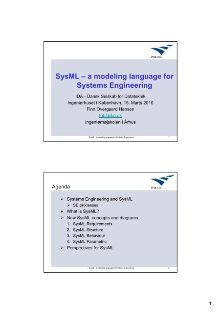
<strong>SysML</strong> – a <strong>modeling</strong> <strong>language</strong> <strong>for</strong><br />
<strong>Systems</strong> <strong>Engineering</strong><br />
IDA - Dansk Selskab <strong>for</strong> Datateknik<br />
Ingeniørhuset i København, 15. Marts 2010<br />
Finn Overgaard Hansen<br />
foh@iha.dk<br />
Ingeniørhøjskolen i Århus<br />
<strong>SysML</strong> - a <strong>modeling</strong> <strong>language</strong> <strong>for</strong> <strong>Systems</strong> <strong>Engineering</strong> 1<br />
Agenda<br />
<strong>Systems</strong> <strong>Engineering</strong> and <strong>SysML</strong><br />
SE processes<br />
What is <strong>SysML</strong><br />
New <strong>SysML</strong> concepts and diagrams<br />
1. <strong>SysML</strong> Requirements<br />
2. <strong>SysML</strong> Structure<br />
3. <strong>SysML</strong> Behaviour<br />
4. <strong>SysML</strong> Parametric<br />
Perspectives <strong>for</strong> <strong>SysML</strong><br />
<strong>SysML</strong> - a <strong>modeling</strong> <strong>language</strong> <strong>for</strong> <strong>Systems</strong> <strong>Engineering</strong> 2<br />
1
<strong>Systems</strong> <strong>Engineering</strong><br />
According to INCOSE:<br />
“<strong>Systems</strong> <strong>Engineering</strong> is an engineering discipline<br />
whose responsibility is creating and executing an<br />
interdisciplinary process to ensure that the<br />
customer and stakeholder’s needs are satisfied<br />
in a high quality, trustworthy, cost efficient and<br />
schedule compliant manner throughout a<br />
system’s entire life cycle”<br />
INCOSE: The International Council on <strong>Systems</strong> <strong>Engineering</strong><br />
Founded in 1990, 6720 members in dec. 2008<br />
<strong>SysML</strong> - a <strong>modeling</strong> <strong>language</strong> <strong>for</strong> <strong>Systems</strong> <strong>Engineering</strong> 3<br />
Model Based <strong>Systems</strong> <strong>Engineering</strong><br />
(MBSE)<br />
• From document-based to model-based approach<br />
• A model-based approach requires <strong>modeling</strong> concepts<br />
and tools<br />
• MBSE: producing and controlling a coherent System<br />
Model<br />
• <strong>SysML</strong> is created to realize an MBSE approach based<br />
on a System model of the wanted system<br />
• <strong>SysML</strong> is a <strong>modeling</strong> <strong>language</strong> not a System<br />
<strong>Engineering</strong> (SE) process<br />
<strong>SysML</strong> - a <strong>modeling</strong> <strong>language</strong> <strong>for</strong> <strong>Systems</strong> <strong>Engineering</strong> 4<br />
2
<strong>Systems</strong> Modeling<br />
<strong>SysML</strong> - a <strong>modeling</strong> <strong>language</strong> <strong>for</strong> <strong>Systems</strong> <strong>Engineering</strong> 5<br />
The SIMILAR (SE) Process<br />
Customer<br />
Needs<br />
State the<br />
Problem<br />
Investigate<br />
Alternatives<br />
Model the<br />
System<br />
Integrate<br />
Launch<br />
the System<br />
Access<br />
Per<strong>for</strong>mance<br />
Re-evaluate Re-evaluate Re-evaluate Re-evaluate Re-evaluate Re-evaluate<br />
Note: All functions are per<strong>for</strong>med in a parallel and iterative manner.<br />
Outputs<br />
Ref. A.T. Bahill and B.Gissing, 1998<br />
<strong>SysML</strong> - a <strong>modeling</strong> <strong>language</strong> <strong>for</strong> <strong>Systems</strong> <strong>Engineering</strong> 6<br />
3
The Harmony (SE) Process (IBM)<br />
• The Harmony process facilitates a seamless transition<br />
from <strong>Systems</strong> <strong>Engineering</strong> to Software <strong>Engineering</strong><br />
• It uses <strong>SysML</strong> exclusively <strong>for</strong> system representation and<br />
specification.<br />
• Harmony process characteristics:<br />
• a scenario-driven and iterative development process<br />
• promotes reuse of test scenarios throughout system<br />
development<br />
<strong>SysML</strong> - a <strong>modeling</strong> <strong>language</strong> <strong>for</strong> <strong>Systems</strong> <strong>Engineering</strong> 7<br />
Harmony Process <strong>for</strong> <strong>Systems</strong> <strong>Engineering</strong><br />
<strong>SysML</strong> - a <strong>modeling</strong> <strong>language</strong> <strong>for</strong> <strong>Systems</strong> <strong>Engineering</strong> 8<br />
4
The Harmony process benefits<br />
• The Harmony process models allow systems<br />
engineers to find design errors early in the<br />
development<br />
• Customer requests can be more efficiently<br />
assessed, incorporated, and given timely feedback<br />
• However, the greatest benefit of a model-driven<br />
process is improved communication<br />
• between engineering disciplines<br />
• between technical and non-technical parties<br />
• using different levels of abstraction<br />
• avoids in<strong>for</strong>mation overload<br />
<strong>SysML</strong> - a <strong>modeling</strong> <strong>language</strong> <strong>for</strong> <strong>Systems</strong> <strong>Engineering</strong> 9<br />
What is <strong>SysML</strong><br />
• A graphical <strong>modeling</strong> <strong>language</strong> created in response to the<br />
UML <strong>for</strong> <strong>Systems</strong> <strong>Engineering</strong> RFP developed by the OMG<br />
and INCOSE.<br />
• a UML Profile that represents a subset of UML 2 with<br />
important extensions<br />
• Supports the specification, analysis, design, verification<br />
and validation of systems that include hardware, software,<br />
data, personnel, procedures, and facilities<br />
• Supports model and data interchange via XMI<br />
<strong>SysML</strong> is a Critical Enabler <strong>for</strong> Model Driven or<br />
Model Based <strong>Systems</strong> <strong>Engineering</strong><br />
<strong>SysML</strong> - a <strong>modeling</strong> <strong>language</strong> <strong>for</strong> <strong>Systems</strong> <strong>Engineering</strong> 10<br />
5
<strong>SysML</strong> Specification History and Status<br />
• Nov. 1997: UML V1.1 launched by OMG<br />
• March 2003: The UML <strong>for</strong> <strong>Systems</strong> <strong>Engineering</strong> RFP<br />
(Request <strong>for</strong> Proposal) was developed jointly by OMG and<br />
INCOSE<br />
• The <strong>SysML</strong> specification was developed in response to<br />
these requirements by the diverse group of tool<br />
vendors, end users, academia, and government<br />
representatives<br />
• Sept. 2007: OMG <strong>SysML</strong> v.1.0<br />
• Nov. 2008: OMG <strong>SysML</strong> v1.1<br />
• (doc.id: <strong>for</strong>mal/2008-11-02, 256 pages)<br />
<strong>SysML</strong> - a <strong>modeling</strong> <strong>language</strong> <strong>for</strong> <strong>Systems</strong> <strong>Engineering</strong> 11<br />
System <strong>Engineering</strong> Technical Processes<br />
Stakeholder<br />
Needs<br />
System Specification<br />
and Design<br />
System Requirements<br />
System Integration<br />
and Test<br />
System<br />
Solution<br />
Component<br />
Requirements<br />
Verified<br />
Components<br />
Design Feedback<br />
Component Design,<br />
Implementation<br />
and Test<br />
Integration & Test Feedback<br />
<strong>SysML</strong> - a <strong>modeling</strong> <strong>language</strong> <strong>for</strong> <strong>Systems</strong> <strong>Engineering</strong> 12<br />
6
System Model and SW/HW Components<br />
<strong>SysML</strong> - a <strong>modeling</strong> <strong>language</strong> <strong>for</strong> <strong>Systems</strong> <strong>Engineering</strong> 13<br />
Comparison of <strong>SysML</strong> and UML<br />
<strong>SysML</strong> - a <strong>modeling</strong> <strong>language</strong> <strong>for</strong> <strong>Systems</strong> <strong>Engineering</strong> 14<br />
7
<strong>SysML</strong> Diagram Taxonomy<br />
<strong>SysML</strong> - a <strong>modeling</strong> <strong>language</strong> <strong>for</strong> <strong>Systems</strong> <strong>Engineering</strong> 15<br />
Major Extensions to UML 2.x<br />
• New Diagram Types<br />
• Requirement Diagram (req)<br />
• Parametric Diagram (par)<br />
• Structure Diagrams<br />
• Block Definition Diagram (bdd)<br />
• Internal Block Diagrams (ibd)<br />
• Activity Diagrams<br />
• extensions <strong>for</strong> continuous flow <strong>modeling</strong><br />
• extensions to support control operators<br />
<strong>SysML</strong> - a <strong>modeling</strong> <strong>language</strong> <strong>for</strong> <strong>Systems</strong> <strong>Engineering</strong> 16<br />
8
The 4 Pillars of <strong>SysML</strong><br />
2: 3:<br />
1:<br />
4:<br />
<strong>SysML</strong> - a <strong>modeling</strong> <strong>language</strong> <strong>for</strong> <strong>Systems</strong> <strong>Engineering</strong> 17<br />
Project activities using <strong>SysML</strong><br />
1. Capture and analyze black box system requirements<br />
• System Context & System Use Cases, Requirement diagrams<br />
2. Develop one ore more candidate system architectures<br />
• Block Definition & Internal Block diagrams<br />
3. Per<strong>for</strong>m engineering trade-off analysis to evaluate and<br />
select the optimal architecture<br />
• Parametric Diagrams<br />
4. Specify component requirements and their traceability<br />
to system requirements<br />
• Requirement diagram<br />
5. Verify the system design by executing system-level<br />
test cases<br />
<strong>SysML</strong> - a <strong>modeling</strong> <strong>language</strong> <strong>for</strong> <strong>Systems</strong> <strong>Engineering</strong> 18<br />
9
1. <strong>SysML</strong> Requirements<br />
• Requirement Diagram – a NEW diagram type<br />
• Graphical visualization of requirements<br />
• Functional<br />
• Non-functional<br />
• Requirements can graphical be related to:<br />
• Other requirements<br />
• Design elements<br />
• Test Cases<br />
• Standard stereotypes:<br />
• derive, satisfy, verify, refine, trace and copy<br />
• Used <strong>for</strong> requirement traceability<br />
<strong>SysML</strong> - a <strong>modeling</strong> <strong>language</strong> <strong>for</strong> <strong>Systems</strong> <strong>Engineering</strong> 19<br />
Requirement Diagram Example<br />
<strong>SysML</strong> - a <strong>modeling</strong> <strong>language</strong> <strong>for</strong> <strong>Systems</strong> <strong>Engineering</strong> 20<br />
10
Requirement Traceability Example<br />
<strong>SysML</strong> - a <strong>modeling</strong> <strong>language</strong> <strong>for</strong> <strong>Systems</strong> <strong>Engineering</strong> 21<br />
2. <strong>SysML</strong> Structure<br />
• UMLs class concept is replaced with the Block concept<br />
• A Block connect to other blocks via Ports<br />
• Class diagrams are replaced with Block Definition<br />
Diagrams (bdd)<br />
• Each Block has an Internal Block Diagram (ibd)<br />
where the internal parts are connected via ports<br />
• a replacement <strong>for</strong> class composite diagrams<br />
• Ports can connect discrete as well as continuous<br />
flows of material or in<strong>for</strong>mation<br />
<strong>SysML</strong> - a <strong>modeling</strong> <strong>language</strong> <strong>for</strong> <strong>Systems</strong> <strong>Engineering</strong> 22<br />
11
Blocks are Basic Structural Elements<br />
<strong>SysML</strong> - a <strong>modeling</strong> <strong>language</strong> <strong>for</strong> <strong>Systems</strong> <strong>Engineering</strong> 23<br />
Blocks and Atomic Flow Ports<br />
• A flow port describes an interaction point <strong>for</strong> items<br />
flowing in or out of a block<br />
• An atomic flow port specifies only a single type of<br />
input or output<br />
optical image: Light<br />
Imaging Assembly<br />
electrical image: Image<br />
external light: Light<br />
Optical Assembly<br />
Optical image: Image<br />
<strong>SysML</strong> - a <strong>modeling</strong> <strong>language</strong> <strong>for</strong> <strong>Systems</strong> <strong>Engineering</strong> 24<br />
12
Blocks and Nonatomic Flow Ports<br />
An interaction point with a complex interface<br />
is modeled as a Nonatomic Port<br />
:Light<br />
«block»<br />
camera i/o:<br />
Camera Interface<br />
Camera <br />
station i/o:<br />
Camera Interface<br />
<br />
«block»<br />
Monitoring<br />
Station<br />
«flow specification»<br />
Camera Interface<br />
flowProperties<br />
out digital video: MPEG4<br />
out analog video: Composite<br />
in control: Control Data<br />
in startup sig: Start Up<br />
A Conjugate flow port<br />
<strong>SysML</strong> - a <strong>modeling</strong> <strong>language</strong> <strong>for</strong> <strong>Systems</strong> <strong>Engineering</strong> 25<br />
Connector and Ports<br />
:Light<br />
cameras:<br />
Camera [4]<br />
camera i/o:<br />
Camera Interface<br />
<br />
station i/o:<br />
Camera Interface<br />
<br />
4 1<br />
:Monitoring<br />
Station<br />
Connector<br />
:Camera Module<br />
:Image<br />
:Image<br />
:Electronics<br />
Assembly<br />
<strong>SysML</strong> - a <strong>modeling</strong> <strong>language</strong> <strong>for</strong> <strong>Systems</strong> <strong>Engineering</strong> 26<br />
13
Delegation Ports<br />
Ibd [Block] Camera [Nested flow]<br />
:Light<br />
:Camera Module<br />
:Electronic Assembly<br />
:Light<br />
:Optical Assembly<br />
:Light<br />
:MPEG Converter<br />
:Video<br />
:MPEG4<br />
<br />
camera i/o:<br />
Camera<br />
Interface<br />
:Imaging Assembly<br />
:Image<br />
:Image<br />
:Image Processor<br />
Delegation port<br />
<strong>SysML</strong> - a <strong>modeling</strong> <strong>language</strong> <strong>for</strong> <strong>Systems</strong> <strong>Engineering</strong> 27<br />
Standard (service based) ports<br />
Provided<br />
interface<br />
Camera<br />
Control<br />
camera requests<br />
Monitoring Station<br />
Required interface<br />
«interface»<br />
Camera Control<br />
operations<br />
getCameraStatus(in cameraId: Integer, in cameraStatus: String)<br />
testCameras()<br />
panCamera(in strength: Integer)<br />
tiltCamera(in strength: Integer)<br />
<strong>SysML</strong> - a <strong>modeling</strong> <strong>language</strong> <strong>for</strong> <strong>Systems</strong> <strong>Engineering</strong> 28<br />
14
Block Definition Diagram Example<br />
<strong>SysML</strong> - a <strong>modeling</strong> <strong>language</strong> <strong>for</strong> <strong>Systems</strong> <strong>Engineering</strong> 29<br />
Internal Block Diagram<br />
<strong>for</strong> Automobile Domain<br />
Port<br />
<strong>SysML</strong> - a <strong>modeling</strong> <strong>language</strong> <strong>for</strong> <strong>Systems</strong> <strong>Engineering</strong> 30<br />
15
Block Definition Diagram Example<br />
<strong>SysML</strong> - a <strong>modeling</strong> <strong>language</strong> <strong>for</strong> <strong>Systems</strong> <strong>Engineering</strong> 31<br />
Internal Block Diagram Example<br />
Part<br />
<strong>SysML</strong> - a <strong>modeling</strong> <strong>language</strong> <strong>for</strong> <strong>Systems</strong> <strong>Engineering</strong> 32<br />
16
3. <strong>SysML</strong> - Behavior<br />
• Activity diagrams are enhanced with new concepts<br />
• Flows can be continuous and model in<strong>for</strong>mation as<br />
well as material flow<br />
• Control flows are introduced<br />
• Activities can have pins<br />
Input control flow<br />
Requried input [1] Requried output [1]<br />
Optional input [0..1]<br />
Action a1<br />
Optional output [0..1]<br />
Output control flow<br />
<strong>SysML</strong> - a <strong>modeling</strong> <strong>language</strong> <strong>for</strong> <strong>Systems</strong> <strong>Engineering</strong> 33<br />
Activity Diagram with parameter nodes<br />
act Operate Camera [Activity Frame]<br />
«optional»<br />
currentImage : Light[0..1]<br />
{stream, direction = in }<br />
«optional»<br />
MPEG output : MPEG4[0..1]<br />
{stream, direction = out }<br />
config :ConfigurationData<br />
{direction = in }<br />
«optional»<br />
composite out : Composite[0..1]<br />
{stream, direction = out }<br />
<strong>SysML</strong> - a <strong>modeling</strong> <strong>language</strong> <strong>for</strong> <strong>Systems</strong> <strong>Engineering</strong> 34<br />
17
Activity Diagram - decomposed<br />
act Operate Camera [Object Flow]<br />
«optional»<br />
current image<br />
{stream}<br />
:CollectImages<br />
Object flow<br />
captured image<br />
{stream}<br />
:CaptureVideo<br />
video out<br />
{stream}<br />
input signal<br />
{stream}<br />
:GenerateVideo<br />
Outputs<br />
Subdiagram<br />
«optional»<br />
MPEG output<br />
{stream}<br />
«optional»<br />
Composite out<br />
{stream}<br />
<strong>SysML</strong> - a <strong>modeling</strong> <strong>language</strong> <strong>for</strong> <strong>Systems</strong> <strong>Engineering</strong> 35<br />
Activity Diagram Notation<br />
Flows can be discrete, streaming or control<br />
<strong>SysML</strong> - a <strong>modeling</strong> <strong>language</strong> <strong>for</strong> <strong>Systems</strong> <strong>Engineering</strong> 36<br />
18
Activity Diagram Example<br />
swimlanes<br />
<strong>SysML</strong> - a <strong>modeling</strong> <strong>language</strong> <strong>for</strong> <strong>Systems</strong> <strong>Engineering</strong> 37<br />
4. <strong>SysML</strong> Parametric<br />
• Parametric Diagram – a NEW diagram type<br />
• Used to express constraints (equations) between value<br />
properties<br />
• Provides support <strong>for</strong> engineering analysis (e.g., per<strong>for</strong>mance,<br />
reliability)<br />
• Constraint block captures equations shown on a bdd<br />
• Expression <strong>language</strong> can be <strong>for</strong>mal (e.g., MathML, OCL) or in<strong>for</strong>mal<br />
• Computational engine is defined by applicable analysis tool and not<br />
by <strong>SysML</strong><br />
• Parametric diagram represents the usage of the<br />
constraints in an analysis context<br />
• Binding of constraint usage to value properties of blocks (e.g., vehicle<br />
mass bound to F= m × a)<br />
• Parametric enable integration of engineering analysis<br />
with design models<br />
<strong>SysML</strong> - a <strong>modeling</strong> <strong>language</strong> <strong>for</strong> <strong>Systems</strong> <strong>Engineering</strong> 38<br />
19
BDD Parametric Constraint Blocks<br />
<strong>SysML</strong> - a <strong>modeling</strong> <strong>language</strong> <strong>for</strong> <strong>Systems</strong> <strong>Engineering</strong> 39<br />
Parametric Diagram - Example<br />
<strong>SysML</strong> - a <strong>modeling</strong> <strong>language</strong> <strong>for</strong> <strong>Systems</strong> <strong>Engineering</strong> 40<br />
20
Combining Model-Driven (MDD) and Model Based<br />
Design (MBD) in Industrial Machine Control<br />
MDD: Model Driven Development<br />
in Rhapsody (IBM)<br />
MBD: Model Based Design<br />
in Simulink (Mathworks)<br />
<strong>SysML</strong> - a <strong>modeling</strong> <strong>language</strong> <strong>for</strong> <strong>Systems</strong> <strong>Engineering</strong> 41<br />
MDD versus MBD Feature Comparison<br />
Table 1. MDD versus MBD feature comparison<br />
<strong>SysML</strong> - a <strong>modeling</strong> <strong>language</strong> <strong>for</strong> <strong>Systems</strong> <strong>Engineering</strong> 42<br />
21
Cross Connecting Model Elements<br />
Structure<br />
ibd [block] Anti-LockController<br />
satisfies<br />
[Internal Block Diagram]<br />
«requirement»<br />
Anti-Lock<br />
Per<strong>for</strong>mance<br />
ibd [block] Anti-LockController<br />
[Internal Block Diagram] d1:TractionDetector<br />
c1:modulator<br />
c1:modulator<br />
Interface<br />
Interface<br />
c1:modulator<br />
interface<br />
allocatedFrom<br />
«ObjectNode»<br />
TractionLoss:<br />
Requirements<br />
allocatedFrom<br />
«activity»DetectLos<br />
d1:Traction<br />
OfTraction<br />
Detector<br />
m1:BrakeModulator<br />
m1:Brake<br />
allocatedFrom<br />
Modulator<br />
«activity»Modulate<br />
BrakingForce<br />
values<br />
DutyCycle: Percentage<br />
satisfy<br />
req [package] VehicleSpecifications<br />
[Requirements Diagram - Braking Requirements]<br />
allocate<br />
value<br />
binding<br />
act PreventLockup [Swimlane Diagram]<br />
«allocate»<br />
act PreventLockup<br />
:TractionDetector<br />
[Activity Diagram]<br />
DetectLossOf<br />
Traction<br />
TractionLoss:<br />
«allocate»<br />
:BrakeModulator<br />
Modulate<br />
BrakingForce<br />
allocatedTo<br />
«connector»c1:modulatorInterface<br />
par [constraintBlock] StraightLineVehicleDynamics [Parametric Diagram]<br />
v.chassis.tire.<br />
Friction:<br />
v.brake.abs.m1.<br />
DutyCycle:<br />
v.brake.rotor.<br />
BrakingForce:<br />
v.Weight:<br />
Behavior<br />
Parametrics<br />
Vehicle System<br />
Specification<br />
Braking Subsystem<br />
Specification<br />
par [constraintBlock] StraightLineVehicleDynamics [Parametric Diagram]<br />
tf:<br />
tl:<br />
bf:<br />
m: c<br />
«requirement»<br />
StoppingDistance<br />
id=“102”<br />
text=”The vehicle shall stop<br />
from 60 mph within 150 ft<br />
on a clean dry surface.”<br />
«requirement»<br />
Anti-LockPer<strong>for</strong>mance<br />
id=”337"<br />
text=”Braking subsystem<br />
shall prevent wheel lockup<br />
under all braking conditions.”<br />
:BrakingForce<br />
Equation<br />
[f = (tf*bf)*(1-tl)]<br />
f:<br />
F:<br />
:Accelleration<br />
Equation<br />
[F = ma]<br />
a:<br />
a:<br />
VerifiedBy<br />
SatisfiedBy<br />
«interaction»MinimumStopp<br />
«block»Anti-LockController<br />
ingDistance<br />
«deriveReqt»<br />
:DistanceEquation<br />
[v = dx/dt]<br />
v:<br />
v:<br />
:VelocityEquation<br />
[a = dv/dt]<br />
«deriveReqt»<br />
verify<br />
x:<br />
v.Position:<br />
<strong>SysML</strong> - a <strong>modeling</strong> <strong>language</strong> <strong>for</strong> <strong>Systems</strong> <strong>Engineering</strong> 43<br />
Vendors of <strong>SysML</strong> tools<br />
• ARTiSAN Software Tools<br />
• EmbeddedPlus <strong>Engineering</strong> (Third party <strong>for</strong> IBM Rational)<br />
• IBM<br />
• Rhapsody<br />
• Tau<br />
• InterCAX<br />
• No Magic<br />
• Papyrus <strong>for</strong> <strong>SysML</strong> (open source eclipse <strong>modeling</strong> tool)<br />
• Software Stencils - Microsoft Visio <strong>SysML</strong> and UML templates<br />
• Sparx <strong>Systems</strong><br />
<strong>SysML</strong> - a <strong>modeling</strong> <strong>language</strong> <strong>for</strong> <strong>Systems</strong> <strong>Engineering</strong> 44<br />
22
Perspectives <strong>for</strong> <strong>SysML</strong><br />
• Enable a common <strong>modeling</strong> <strong>language</strong> and model<br />
across engineering disciplines<br />
• Enable traceability between disciplines<br />
• Enable different kinds of system analysis<br />
• Enable integration of discrete and continuous based<br />
<strong>modeling</strong> tools<br />
• Critical enabler <strong>for</strong> Model Based System <strong>Engineering</strong><br />
with tool support<br />
<strong>SysML</strong> - a <strong>modeling</strong> <strong>language</strong> <strong>for</strong> <strong>Systems</strong> <strong>Engineering</strong> 45<br />
Summary<br />
• <strong>SysML</strong> a common <strong>modeling</strong> <strong>language</strong> <strong>for</strong> different<br />
disciplines e.g. Hardware, Software and Mechanics<br />
• New and important concepts <strong>for</strong> cross disciplinary<br />
analysis of system properties (e.g. parametric)<br />
• Blocks and ports as general <strong>modeling</strong> elements<br />
• Important enhancement to activity diagrams<br />
• Lot of support <strong>for</strong> traceability between models and<br />
model elements<br />
• Must be supported by an appropriate SE process<br />
<strong>SysML</strong> - a <strong>modeling</strong> <strong>language</strong> <strong>for</strong> <strong>Systems</strong> <strong>Engineering</strong> 46<br />
23
References<br />
• OMGs <strong>SysML</strong> homepage: www.omgsysml.org<br />
• INCOSE organization: www.incose.org<br />
• “Re-evaluating systems engineering concepts using systems<br />
thinking”, A.T. Bahill and B. Gissing, IEEE Transaction on <strong>Systems</strong>,<br />
Man and Cybernetics, Part C, 28 (4), 516-527, 1988.<br />
• IBM Rational Harmony:<br />
• http://www-01.ibm.com/software/rational/services/harmony/<br />
• Books:<br />
• ”A Practical Guide to <strong>SysML</strong> – The System Modeling<br />
Language”, San<strong>for</strong>d Friedenthal, Allan Moore, Rick Steiner,<br />
Elsevier, 2008.<br />
• ”<strong>Systems</strong> <strong>Engineering</strong> with <strong>SysML</strong>/UML – Modeling,<br />
Analysis, Design”, Tim Weilkiens, Elsevier, 2007.<br />
<strong>SysML</strong> - a <strong>modeling</strong> <strong>language</strong> <strong>for</strong> <strong>Systems</strong> <strong>Engineering</strong> 47<br />
<strong>SysML</strong><br />
<strong>SysML</strong> - a <strong>modeling</strong> <strong>language</strong> <strong>for</strong> <strong>Systems</strong> <strong>Engineering</strong> 48<br />
24