
Create successful ePaper yourself
Turn your PDF publications into a flip-book with our unique Google optimized e-Paper software.
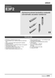
Fieldbus Segment Protector<br />
*-<strong>JBSC</strong>-*<br />
Fieldbus junction box with integrated short-circuit current limitation<br />
Type code see overleaf<br />
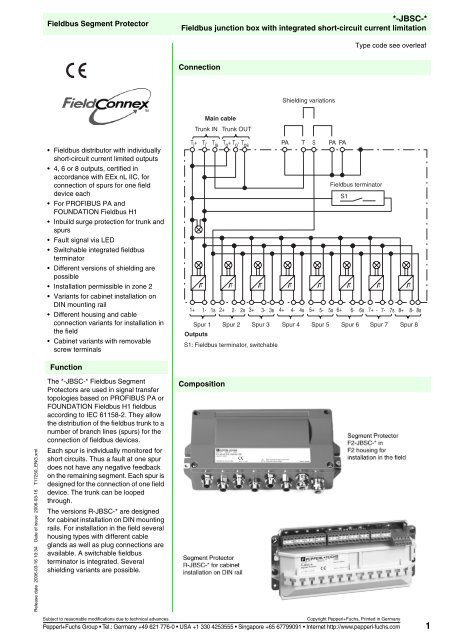
Connection<br />
Shielding variations<br />
Main cable<br />
Trunk IN Trunk OUT<br />
• Fieldbus distributor with individually<br />
short-circuit current limited outputs<br />
• 4, 6 or 8 outputs, certified in<br />
accordance with EEx nL IIC, for<br />
connection of spurs for one field<br />
device each<br />
• For PROFIBUS PA and<br />
FOUNDATION Fieldbus H1<br />
• Inbuild surge protection for trunk and<br />
spurs<br />
• Fault signal via LED<br />
• Switchable integrated fieldbus<br />
terminator<br />
• Different versions of shielding are<br />
possible<br />
• Installation permissible in zone 2<br />
• Variants for cabinet installation on<br />
DIN mounting rail<br />
• Different housing and cable<br />
connection variants for installation in<br />
the field<br />
• Cabinet variants with removable<br />
screw terminals<br />
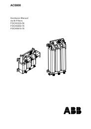
T i + T i - T is T o + T o - T os<br />
PA T S PA PA<br />
Fieldbus terminator<br />
S1<br />
I<br />
I<br />
I<br />
I<br />
I<br />
I<br />
I<br />
I<br />
1+ 1- 1s 2+ 2- 2s 3+ 3- 3s 4+ 4- 4s 5+ 5- 5s 6+ 6- 6s 7+ - 7- 7s 8+ 8- 8s<br />
Spur 1<br />
Outputs<br />
Spur 2 Spur 3 Spur 4 Spur 5 Spur 6 Spur 7 Spur 8<br />
S1: Fieldbus terminator, switchable<br />
Function<br />
Release date 2006-03-16 10:34 Date of issue 2006-03-16 T17250_ENG.xml<br />
The *-<strong>JBSC</strong>-* Fieldbus Segment<br />
Protectors are used in signal transfer<br />
topologies based on PROFIBUS PA or<br />
FOUNDATION Fieldbus H1 fieldbus<br />
according to IEC 61158-2. They allow<br />
the distribution of the fieldbus trunk to a<br />
number of branch lines (spurs) for the<br />
connection of fieldbus devices.<br />
Each spur is individually monitored for<br />
short circuits. Thus a fault at one spur<br />
does not have any negative feedback<br />
on the remaining segment. Each spur is<br />
designed for the connection of one field<br />
device. The trunk can be looped<br />
through.<br />
The versions R-<strong>JBSC</strong>-* are designed<br />
for cabinet installation on DIN mounting<br />
rails. For installation in the field several<br />
housing types with different cable<br />
glands as well as plug connections are<br />
available. A switchable fieldbus<br />
terminator is integrated. Several<br />
shielding variants are possible.<br />
Composition<br />
Subject to reasonable modifications due to technical advances.<br />
Copyright Pepperl+Fuchs, Printed in Germany<br />
Pepperl+Fuchs Group • Tel.: Germany +49 621 776-0 • USA +1 330 4253555 • Singapore +65 67799091 • Internet http://www.pepperl-fuchs.com 1
Technical data<br />
*-<strong>JBSC</strong>-*<br />
Release date 2006-03-16 10:34 Date of issue 2006-03-16 T17250_ENG.xml<br />
Fieldbus interface<br />
Main cable (Trunk)<br />
Connection see table 1<br />
Rated voltage<br />
9 ... 31 V DC<br />
Rated current<br />
≤ 6 A<br />
Screening option<br />
looped through direct to earth potential, trunk and outputs<br />
Outputs<br />
Connection see table 1<br />
Rated voltage<br />
≤ 31 V<br />
Rated current<br />
≤ 40 mA<br />
Short-circuit current<br />
Screening option<br />
Self current consumption<br />
Voltage drop main cable/outputs<br />
≤ 45 mA<br />
looped through direct to earth potential, trunk and outputs<br />
max. 9 mA<br />
≤ 1.3 V<br />
Terminator<br />
switchable 100 Ω integrated<br />
Surge protection<br />
trunk, spurs overvoltage protected if voltage exceeds typ. 39 V, max. 41 V<br />
Indicators/operating means<br />
LED voltage Fieldbus<br />
green: Fieldbus voltage > 10V<br />
LED status Fieldbus<br />
yellow: bus activity<br />
LED state outputs<br />
red flashing: short-circuit<br />
Directive conformity<br />
Electromagnetic compatibility<br />
standards<br />
Directive 89/336/EC EN 61326<br />
Standard conformity<br />
Electromagnetic compatibility NE 21<br />
Protection degree IEC 60529<br />
Fieldbus standard IEC 61158-2<br />
Climatic conditions IEC 60721<br />
Ambient conditions<br />
Ambient temperature see table 2<br />
Storage temperature -40 ... 85 °C (233 ... 358 K)<br />
Shock resistance<br />
15 g , 11 ms<br />
Vibration resistance<br />
5 g , 10 ... 150 Hz<br />
Mechanical specifications<br />
Connection type see table 2<br />
Core cross-section up to 2.5 mm 2<br />
Cable diameter see table 3<br />
Cable gland see table 2<br />
Housing see figures 1 ... 3<br />
Housing material<br />
R... DIN rail housing PA 6.6<br />
F2... aluminium housing<br />
ALSI12 (Cu) DIN1725 (Si 1,2%), anodised<br />
F6... stainless steel housing<br />
1.4404 (S316L)<br />
Protection degree<br />
R... DIN rail housing<br />
IP20<br />
F2... aluminium housing<br />
IP67<br />
F6... stainless steel housing<br />
IP66<br />
Mass<br />
R... DIN rail housing<br />
380 g<br />
F2... aluminium housing<br />
1800 g<br />
F6... stainless steel housing<br />
2450 g<br />
Mounting<br />
panel or DIN rail mounting<br />
Data for application in conjunction<br />
with hazardous areas<br />
Main cable (Trunk)<br />
Rated current<br />
≤ 2.5 A<br />
Outputs<br />
Voltage U o 32 V<br />
Current I o 45 mA<br />
Inductance L o 0.25 mH<br />
Capacitance C o 100 nF<br />
Statement of conformity<br />
TÜV 04 ATEX 2465 X<br />
Group, category, type of protection, ¬ II 3 G EEx nA [L] IIC T4<br />
temperature classification<br />
Directive conformity<br />
Subject to reasonable modifications due to technical advances.<br />
Copyright Pepperl+Fuchs, Printed in Germany<br />
Pepperl+Fuchs Group • Tel.: Germany +49 621 776-0 • USA +1 330 4253555 • Singapore +65 67799091 • Internet http://www.pepperl-fuchs.com<br />
2
Technical data<br />
*-<strong>JBSC</strong>-*<br />
Directive 94/9 EC EN 50021<br />
Release date 2006-03-16 10:34 Date of issue 2006-03-16 T17250_ENG.xml<br />
Subject to reasonable modifications due to technical advances.<br />
Copyright Pepperl+Fuchs, Printed in Germany<br />
Pepperl+Fuchs Group • Tel.: Germany +49 621 776-0 • USA +1 330 4253555 • Singapore +65 67799091 • Internet http://www.pepperl-fuchs.com<br />
3
Technical data<br />
*-<strong>JBSC</strong>-*<br />
Type code/order designation<br />
Type of housing<br />
F2<br />
F6<br />
R<br />
Field housing with 4, 6 or 8 outputs, aluminium<br />
Field housing with 4, 6 or 8 outputs, stainless steel<br />
without field housing, for mounting in cabinet on DIN rail<br />
Type of device<br />
<strong>JBSC</strong> Segment Protector with short-circuit power limitation<br />
Explosion protection method<br />
leave blank for general purpose applications in non-hazardous areas and Zone 2/Class I, Div. 2<br />
Number of outputs<br />
4<br />
6<br />
8<br />
Type of cable connection<br />
Fieldbus-independent: variants with field housing and cable glands or without field housing<br />
FF Field housing with plug connection for FOUNDATION Fieldbus<br />
PA Field housing with plug connection for PROFIBUS PA<br />
Connection of trunk cable<br />
similar to output cable resp. variant without field housing<br />
CG Cable gland, plastic, M20<br />
CGB Cable gland, nickel plated brass, M20<br />
CGS Cable gland, stainless steel, M20<br />
CGAB Cable gland for armoured cables, nickel plated brass, M20<br />
7/8S Plug connection 7/8", stainless steel<br />
M12B Plug connection M12 x 1, nickel plated brass<br />
M12S Plug connection M12 x 1, stainless steel<br />
Connection of output cable (spur)<br />
Variant without field housing<br />
COM Variant without field housing, plug-in terminals<br />
CG Cable gland, plastic, M16<br />
CGB Cable gland, nickel plated brass, M16<br />
CGS Cable gland, stainless steel, M16<br />
CGAB Cable gland for armoured cables, nickel plated brass, M20<br />
CG2 Cable gland, plastic, M20<br />
CGS2 Cable gland, stainless steel, M20<br />
7/8S Plug connection, stainless steel, 7/8"<br />
M12B Plug connection, nickel plated brass, M12 x 1<br />
M12S Plug connection, stainless steel, M12 x 1<br />
- <strong>JBSC</strong> - . . .<br />
A - B - C D . E . F . G<br />
Identification for assignment of the type code to the following tables<br />
Example:<br />
Release date 2006-03-16 10:34 Date of issue 2006-03-16 T17250_ENG.xml<br />
Segment Protector for cabinet installation on standard DIN rail, 8 outputs for FOUNDATION Fieldbus H1 and PROFIBUS PA,<br />
plug-in screw terminals: R-<strong>JBSC</strong>-8.COM<br />
Example:<br />
Segment Protector in field housing aluminium, trunk cable glands stainless steel, 6 outputs plug connection 7/8" stainless steel,<br />
pin assignment for FOUNDATION Fieldbus H1: F2-<strong>JBSC</strong>-6.FF.CGS.7/8S<br />
Note: Not all variants are available. For available variants please refer to the electronic configuration tool or contact<br />
your Pepperl+Fuchs representative.<br />
Subject to reasonable modifications due to technical advances.<br />
Copyright Pepperl+Fuchs, Printed in Germany<br />
Pepperl+Fuchs Group • Tel.: Germany +49 621 776-0 • USA +1 330 4253555 • Singapore +65 67799091 • Internet http://www.pepperl-fuchs.com<br />
4
Technical data<br />
*-<strong>JBSC</strong>-*<br />
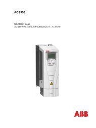
Dimensions<br />
LED<br />
Connections<br />
Trunk<br />
Fieldbus terminator,<br />
switchable<br />
Connections Spurs<br />
217<br />
Shield brigdes<br />
DIN mounting rail<br />
64<br />
SPUR 1 SPUR 2 SPUR 3 SPUR 4 SPUR 5 SPUR 6 SPUR 7 SPUR 8 TRUNK IN TRUNK OUT<br />
100<br />
Cable fixing<br />
with cable tie<br />
Mounting on<br />
DIN rail<br />
Figure 1: R-<strong>JBSC</strong>-* for cabinet installation on DIN rail, terminal connections see table 1<br />
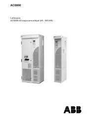
258<br />
228<br />
240<br />
Function unit<br />
similar R-<strong>JBSC</strong>-*<br />
see above<br />
for fixing<br />
with screws<br />
M6<br />
x<br />
114<br />
9,5<br />
84<br />
(57)<br />
Earthing<br />
point<br />
Release date 2006-03-16 10:34 Date of issue 2006-03-16 T17250_ENG.xml<br />
SW<br />
Spurs<br />
Trunk IN<br />
Figure 2: F2-<strong>JBSC</strong>-* with aluminium housing, connection variants and dimensions see table 2 ... 4<br />
Trunk OUT<br />
Subject to reasonable modifications due to technical advances.<br />
Copyright Pepperl+Fuchs, Printed in Germany<br />
Pepperl+Fuchs Group • Tel.: Germany +49 621 776-0 • USA +1 330 4253555 • Singapore +65 67799091 • Internet http://www.pepperl-fuchs.com<br />
5
Technical data<br />
*-<strong>JBSC</strong>-*<br />
Function unit similar<br />
R-<strong>JBSC</strong>-* see above<br />
For mounting<br />
with screws<br />
M6<br />
320<br />
300<br />
280<br />
Y<br />
170<br />
Earthing<br />
point<br />
SW<br />
Spurs<br />
Trunk IN<br />
Trunk OUT<br />
Height of F6 housing: 86 mm<br />
Figure 3: F6-<strong>JBSC</strong>-* with stainless steel housing, connection variants and dimensions see tables 2 ... 4<br />
Electrical connection<br />
Release date 2006-03-16 10:34 Date of issue 2006-03-16 T17250_ENG.xml<br />
Table 1: Connection of terminals<br />
Terminals<br />
Function<br />
1+, 2+, 3+, 4+, 5+, 6+, 7+, 8+ Output (spur) +<br />
1-, 2-, 3-, 4-, 5-, 6-, 7-, 8- Output (spur) -<br />
1s, 2s, 3s, 4s, 5s, 6s, 7s, 8s Output (spur) shield<br />
T i + Trunk IN +<br />
T i - Trunk IN -<br />
T is<br />
Trunk IN shield<br />
T o + Trunk OUT +<br />
T o - Trunk OUT -<br />
T os<br />
Trunk OUT shield<br />
T<br />
Trunk, shield bridge<br />
S<br />
Outputs, shield bridge<br />
PA<br />
Potential equalization<br />
The terminals T is and T os are connected internally with terminal T.<br />
The terminals 1s ... 8s are connected internally with terminal S.<br />
The terminals PA are connected with the external earthing point (versions with field housing only).<br />
Different connections of the terminals T, S and PA allow to choose different shielding concepts.<br />
Variants R-<strong>JBSC</strong>-*.COM have plug-in terminals.<br />
Subject to reasonable modifications due to technical advances.<br />
Copyright Pepperl+Fuchs, Printed in Germany<br />
Pepperl+Fuchs Group • Tel.: Germany +49 621 776-0 • USA +1 330 4253555 • Singapore +65 67799091 • Internet http://www.pepperl-fuchs.com<br />
6
Technical data<br />
*-<strong>JBSC</strong>-*<br />
Table 2: Variations of cable connections, housing types and temperature ranges<br />
Type of connection,<br />
identification F, G<br />
Type of cable connection<br />
Number of outputs<br />
(spurs)<br />
identification D<br />
4 6 8<br />
F2 housing,<br />
outside<br />
dimension<br />
"X" (mm)<br />
F6 housing,<br />
outside<br />
dimension<br />
"Y" (mm)<br />
SW<br />
(mm)<br />
Temperature<br />
range<br />
(°C)<br />
CG Terminals, cable glands plastic X X X 140 200 20 -30 ... 70<br />
CGB Terminals, cable glands nickel plated brass X X X 140 n.a. 20 -40 ... 70<br />
CGS Terminals, cable glands stainless steel X X – 140 200 22 -40 ... 70<br />
CGAB<br />
Terminals, cable glands nickel plated brass for<br />
armoured cable<br />
X – – 160 220 24 -40 ... 70<br />
CG2 Terminals, cable glands plastic X – – 140 200 24 -30 ... 70<br />
CGS2 Terminals, cable glands stainless steel X – – 140 200 24 -40 ... 70<br />
M12B Plug connection M12 x 1, nickel plated brass X X X 135 195 n.a. -25 ... 70<br />
M12S Plug connection M12 x 1, stainless steel X X X 135 195 n.a. -25 ... 70<br />
7/8S Plug connection 7/8", stainless steel X X X 135 195 n.a. -40 ... 70<br />
without field housing Terminals<br />
(R-<strong>JBSC</strong>-*)<br />
X X X n.a. n.a. n.a. -50 ... 70<br />
Table 3: Cable diameter depending on cable gland<br />
Type of connection Cable diameter (mm)<br />
identification F, G<br />
CG 5 ... 10<br />
CGB 5 ... 10<br />
CGS 5 ... 10<br />
CGAB<br />
8.5 ... 16 outside<br />
6 ... 12 inside<br />
0 ... 1.25 armour<br />
CG2 7 ... 12<br />
CGS2 7 ... 12<br />
Table 4: Pin assignment of plug connections<br />
Outputs<br />
Trunk OUT<br />
Trunk IN<br />
Outputs<br />
Trunk OUT<br />
Trunk IN<br />
3<br />
4<br />
4<br />
3<br />
3<br />
1<br />
1<br />
3<br />
2<br />
1<br />
1<br />
2<br />
4<br />
2<br />
2<br />
4<br />
Plug connection M12 x 1 Plug connection 7/8"<br />
Pin PROFIBUS PA FOUNDATION Fieldbus<br />
1 PA+ Data-<br />
2 n.c. (GND) Data+<br />
3 PA- Shield<br />
4 Shield n.c. (GND)<br />
Note for connector variants:<br />
Outputs (spur, trunk Out) are always sockets (female).<br />
Trunk IN is always plug (male).<br />
Release date 2006-03-16 10:34 Date of issue 2006-03-16 T17250_ENG.xml<br />
Installation note<br />
see manual<br />
Accessories<br />
Socket M12 x 1: blind plug VAZ-V1-B<br />
Socket M20: bind plug CG EX PLUG MT 20X<br />
Socket 7/8": blind plug V9-R-F-COV<br />
Subject to reasonable modifications due to technical advances.<br />
Copyright Pepperl+Fuchs, Printed in Germany<br />
Pepperl+Fuchs Group • Tel.: Germany +49 621 776-0 • USA +1 330 4253555 • Singapore +65 67799091 • Internet http://www.pepperl-fuchs.com<br />
7