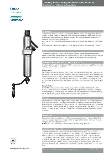
Sampling Valves - Yarway Model 56 / Narvik Model 36 - avintos
Sampling Valves - Yarway Model 56 / Narvik Model 36 - avintos
Sampling Valves - Yarway Model 56 / Narvik Model 36 - avintos

You also want an ePaper? Increase the reach of your titles
YUMPU automatically turns print PDFs into web optimized ePapers that Google loves.
<strong>Sampling</strong> <strong>Valves</strong> - <strong>Yarway</strong> <strong>Model</strong> <strong>56</strong> / <strong>Narvik</strong> <strong>Model</strong> <strong>36</strong><br />
Installation and Maintenance Instructions<br />
Unpacking<br />
The <strong>Yarway</strong> Sample Valve and the <strong>Narvik</strong> Sampler Valve are packed with the greatest of care in<br />
wooden boxes or cartons for protection during handling or transit to site. If it is found, however,<br />
that damage has occurred during shipment, then this should be reported immediately to your<br />
forwarder or <strong>Narvik</strong>/<strong>Yarway</strong> representative.<br />
Particular care should be taken with valves equipped with limit switches, air cylinder, glass bottle,<br />
etc.<br />
If the unit needs to be stored, please refer to the storage procedure as described at the end.<br />
Installation<br />
The <strong>Yarway</strong> Sample Valve and the <strong>Narvik</strong> Sampler Valve are supplied with either threaded or<br />
flanged connections. A suitable sealing compound as PTFE tape or equivalent should be used for<br />
sealing. Do not apply any force to the air cylinder when screwing-in the valve assembly.<br />
Dismantling instructions (see fig. 2 up to including fig. 5)<br />
Overhauling the Sample Valve / Sampler Valve is best carried out after removing it from the vessel,<br />
drip ring or pipeline to the workshop.<br />
Sample Valve<br />
Grind-off the tackweld between the stem bushing (12) and the valve bonnet (11). Untighten and<br />
remove the 4 cap screws. Remove the bonnet assembly, unscrew the stem bushing for the stem<br />
(10) and remove stem / coupling / plunger assembly. Disassemble the plunger (5) by removing the<br />
2 half couplings (9) that hold it to the stem. Remove other valve internals, care should be taken<br />
not to lose the securing ball (3). In special alloy valves, a key may be fitted in place of the securing<br />
ball.<br />
Sampler Valve<br />
Grind-off the tackweld between the stem bushing and the valve bonnet. Unscrew the stem<br />
bushing counter clockwise. Remove the stem bushing together with the stem, the coupling (9)<br />
and the plunger (5). Remove other valve internals, care should be taken not to lose the securing<br />
ball. In special alloy valves, a key may be fitted in place of the securing ball.<br />
Cleaning<br />
Clean all internals thoroughly using a suitable solvent. When necessary, use a find grade grinding<br />
cloth to repolish surfaces. The plunger should be free of longitudinal scratches or score marks.<br />
Plunger can not be remachined but may be ground with a fine grade of grinding cloth. Special are<br />
should be taken to clean the internal bore of the body where the upper/lower seal rings (2) (6) are<br />
located, as sealing integrity is very much dependent on the cleanness and smoothness of these<br />
surfaces.<br />
Reassembly<br />
Reassembly of the valve is the reverse of the procedure given above. Do not use old seal rings,<br />
otherwise sealing integrity may be impaired. Do not forget to tackweld the bushing to the body,<br />
using a 309 or similar type electrode.<br />
Note: <strong>Narvik</strong> can supply a special tool to facilitate the reassembly of the valve.<br />
Actuation (see fig. 1 and fig. 4)<br />
The <strong>Yarway</strong> Sample Valve and the <strong>Narvik</strong> Sampler Valve can be supplied with air cylinder<br />
actuators. These are specially adapted “Festo” type cylinders (other manufacturer type upon<br />
request) which are not commercially available through the normal “Festo” distribution network.<br />
The cylinder is a non-repairable item. Cylinders are made to individual order and this should be<br />
considered when deciding upon which spare parts should be retained at site. When ordering<br />
replacement cylinders, the valve plunger extension should be specified. Always use a clean dry<br />
instrument air supply with this equipment. The air supply pressure should have a minimum of 3.5<br />
bar.<br />
www.tycovalves-eu.com<br />
Tyco reserves the right to change the contents without notice<br />
NRVSB-0050-EN-0710
<strong>Sampling</strong> <strong>Valves</strong> - <strong>Yarway</strong> <strong>Model</strong> <strong>56</strong> / <strong>Narvik</strong> <strong>Model</strong> <strong>36</strong><br />
Installation and Maintenance Instructions<br />
Temperature limitations<br />
Sample Valve / Sampler Valve are supplied with various seal materials. Carefully check the original<br />
seal type before ordering spare parts.<br />
Maximum temperature seals are indicated in the product documentation.<br />
Maintenance<br />
The <strong>Yarway</strong> Sample Valve and the <strong>Narvik</strong> Sampler Valve require little maintenance. Regular<br />
greasing of the stem, however, is recommended using a high quality molybdenum grease.<br />
Inspection<br />
Sample Valve / Sampler Valve body, plunger, glands and seal rings should be smooth and free<br />
from scratches, indentations or any other physical damage, or damaged internal components will<br />
impair sealing capability and should be replaced if this is evident. Always renew sealing rings, as a<br />
matter of course, if the valve is dismantled for any reason.<br />
Valve testing<br />
the hydrostatic and leakage testing at the factory is performed based on the following parameters<br />
using water:<br />
- Hydrostatic test of the body (valve open) at 94.0 bar for 1 minute<br />
- Packing leakage testing (valve closed) at 40.0 bar for 1 minute<br />
Acceptance criteria: no visible leakage<br />
Notes<br />
- The maximum operating temperature is limited by the seal ring material. Check the identification<br />
plate for details.<br />
- If there is evidence of leakage, and the gland springs are adjusted correctly, then do not tighten<br />
further but dismantle the valve for inspection.<br />
Figure 1 - Pneumatic systems (examples)<br />
Pressurized air net<br />
Vent<br />
Air cylinder<br />
Solenoid<br />
valve<br />
Air cylinder with<br />
‘air failure to<br />
close’ system<br />
Optional<br />
Capacity<br />
tank<br />
Tyco reserves the right to change the contents without notice page 2
<strong>Sampling</strong> <strong>Valves</strong> - <strong>Yarway</strong> <strong>Model</strong> <strong>56</strong> / <strong>Narvik</strong> <strong>Model</strong> <strong>36</strong><br />
Installation and Maintenance Instructions<br />
3<br />
/4 ”<br />
14<br />
1 •<br />
45˚<br />
2 •<br />
3 •<br />
4 •<br />
5 •<br />
6 •<br />
7 •<br />
8 •<br />
9 •<br />
10 •<br />
11 •<br />
12 •<br />
1 /2 ”<br />
Table 1 - Standard materials<br />
Item Name Material Equivalent<br />
1 Body (316Nb) 1.4581<br />
2 * • Lower seal PTFE PTFE<br />
3 • Securing ball St. Steel St. Steel<br />
4 Lower gland A182 F316L 1.4404<br />
5 • Plunger A182 F316L 1.4404<br />
6 * • Upper seal PTFE PTFE<br />
7 Upper gland A182 F316L 1.4404<br />
8 • Belleville washers 50 CrV 4 50 CrV 4<br />
9 Coupling AISI 410 1.4006<br />
10 • Stem AISI 410 1.4006<br />
11 Bonnet A351 CF8 1.4308<br />
12 • Stem bushing GGG60 zinc plated GGG60 zinc plated<br />
13 Crank C.Steel zinc plated C.Steel zinc plated<br />
14 Washer St. Steel St. Steel<br />
15 Cap nut St. Steel St. Steel<br />
16 Handle C.Steel zinc plated C.Steel zinc plated<br />
* Other materials upon request<br />
● Recommended spares<br />
Weight: 1.8 kg<br />
For other penetration lengths and/or materials, please consult <strong>Narvik</strong>-<strong>Yarway</strong> or your<br />
local Tyco representative<br />
13 •<br />
14 •<br />
15 •<br />
16 •<br />
Figure 2 - <strong>Yarway</strong> 1/2” Sample Valve<br />
Tyco reserves the right to change the contents without notice page 3
<strong>Sampling</strong> <strong>Valves</strong> - <strong>Yarway</strong> <strong>Model</strong> <strong>56</strong> / <strong>Narvik</strong> <strong>Model</strong> <strong>36</strong><br />
Installation and Maintenance Instructions<br />
25,4<br />
1 1 /2 ”<br />
•<br />
1<br />
•<br />
45˚<br />
2<br />
Table 2 - Standard materials<br />
•<br />
3<br />
Item Name Material Equivalent<br />
1 Body A351 CF8M 1.4408<br />
2 * • Lower seal PTFE PTFE<br />
3 • Securing ball St. Steel St. Steel<br />
4 Lower gland A182 F316L 1.4404<br />
5 • Plunger A182 F316L 1.4404<br />
6 * • Upper seal PTFE PTFE<br />
7 Upper gland A182 F316L 1.4404<br />
8 Helical spring - 1.1200<br />
9 ** Coupling AISI 630 1.4542<br />
10 • Stem AISI 420 1.4021<br />
11 Bonnet A351 CF8M 1.4408<br />
12 • Stem bushing GGG60 zinc plated GGG60 zinc plated<br />
13 Handwheel Aluminium Aluminium<br />
14 Washer St. Steel St. Steel<br />
15 Cap nut St. Steel St. Steel<br />
* Other materials upon request<br />
** For Copper-free environments, material 1.4005<br />
● Recommended spares<br />
Weight: 6.5 kg<br />
For other penetration lengths and/or materials, please consult <strong>Narvik</strong>-<strong>Yarway</strong> or your<br />
local Tyco representative<br />
1 ”<br />
•<br />
•<br />
•<br />
•<br />
•<br />
•<br />
•<br />
•<br />
•<br />
5<br />
4<br />
6<br />
7<br />
9<br />
10<br />
8<br />
11<br />
12<br />
•<br />
13<br />
•<br />
•<br />
14<br />
15<br />
Figure 3 - <strong>Narvik</strong> Sampler Valve 1”<br />
Tyco reserves the right to change the contents without notice page 4
<strong>Sampling</strong> <strong>Valves</strong> - <strong>Yarway</strong> <strong>Model</strong> <strong>56</strong> / <strong>Narvik</strong> <strong>Model</strong> <strong>36</strong><br />
Installation and Maintenance Instructions<br />
3<br />
/4 ”<br />
14<br />
1 •<br />
2 •<br />
3 •<br />
4 •<br />
5 •<br />
6 •<br />
7<br />
•<br />
8<br />
•<br />
9<br />
10<br />
11<br />
16<br />
17<br />
45˚<br />
•<br />
•<br />
•<br />
•<br />
•<br />
1 /2 ”<br />
Table 3 - Standard materials<br />
Item Name Material Equivalent<br />
1 Body (316Nb) 1.4581<br />
2 * • Lower seal PTFE PTFE<br />
3 • Securing ball St. Steel St. Steel<br />
4 Lower gland A182 F316L 1.4404<br />
5 • Plunger A182 F316L 1.4404<br />
6 * • Upper seal PTFE PTFE<br />
7 Upper gland A182 F316L 1.4404<br />
8 • Belleville washers 50 CrV 4 50 CrV4<br />
9 Coupling AISI 410 1.4008<br />
10 • Stem AISI 410 1.4008<br />
11 Bonnet A351 CF8 1.4308<br />
16 Adaptor<br />
17 ** Air cylinder. “Sempress” Double act<br />
18 O-rings Rubber Rubber<br />
19 Piston rod St. Steel 1.4104<br />
20 Cylinder Aluminium Aluminium<br />
21 Guiding Synthetic Synthetic<br />
* Other materials upon request<br />
** Max. air supply: 10 bar<br />
Pneumatic connection: G3/8”<br />
Spring return, upon request<br />
● Recommended spares<br />
Weight: 5.3 kg<br />
For other penetration lengths and/or materials, please consult <strong>Narvik</strong>-<strong>Yarway</strong> or your<br />
local Tyco representative<br />
18<br />
19<br />
•<br />
•<br />
20<br />
•<br />
21<br />
•<br />
18<br />
•<br />
Figure 4 - <strong>Yarway</strong> 1/2” Sample Valve with air cylinder<br />
Tyco reserves the right to change the contents without notice page 5
<strong>Sampling</strong> <strong>Valves</strong> - <strong>Yarway</strong> <strong>Model</strong> <strong>56</strong> / <strong>Narvik</strong> <strong>Model</strong> <strong>36</strong><br />
Installation and Maintenance Instructions<br />
3<br />
/4 ”<br />
14<br />
- R -<br />
1 •<br />
45˚<br />
2 •<br />
3 •<br />
4<br />
5<br />
•<br />
•<br />
6 •<br />
7 •<br />
8 •<br />
9 •<br />
- D -<br />
- C -<br />
10 •<br />
11 •<br />
- A -<br />
250 ml<br />
12 •<br />
13 •<br />
14 •<br />
15 •<br />
16 •<br />
- E -<br />
- B -<br />
Figure 5 - <strong>Yarway</strong> 1/2” Sample Valve with bottle holder<br />
Table 5 - Dimensions (mm)<br />
R A B C D E<br />
0 271 60 45, 5 55 60<br />
50 321 110 45, 5 55 60<br />
Table 4 - Standard materials<br />
Item Name Material Equivalent<br />
1 Body (316Nb) 1.4581<br />
2 * • Lower seal PTFE PTFE<br />
3 • Securing ball St. Steel St. Steel<br />
4 Lower gland A182 F316L 1.4404<br />
5 • Plunger A182 F316L 1.4404<br />
6 * • Upper seal PTFE PTFE<br />
7 Upper gland A182 F316L 1.4404<br />
8 • Belleville washers 50 CrV 4 50 CrV4<br />
9 Coupling AISI 410 1.4006<br />
10 • Stem AISI 410 1.4006<br />
11 Bonnet A351 CF8 1.4008<br />
12 • Stem bushing GGG60 zinc plated GGG60 zinc plated<br />
13 Crank C.Steel zinc plated C.Steel zinc plated<br />
14 Washer St. Steel St. Steel<br />
15 Cap nut St. Steel St. Steel<br />
16 Handle C.Steel zinc plated C.Steel zinc plated<br />
* Other materials upon request<br />
● Recommended spares<br />
Weight: 3.2 kg<br />
Dimensions may be subject to change<br />
without prior notification<br />
<strong>Narvik</strong> will provide a certified dimensional<br />
drawing upon request<br />
For other penetration lengths and/or<br />
materials, please consult <strong>Narvik</strong>-<strong>Yarway</strong> or<br />
your local Tyco representative.<br />
Tyco reserves the right to change the contents without notice page 6
<strong>Sampling</strong> <strong>Valves</strong> - <strong>Yarway</strong> <strong>Model</strong> <strong>56</strong> / <strong>Narvik</strong> <strong>Model</strong> <strong>36</strong><br />
Installation and Maintenance Instructions<br />
Storage procedure<br />
Upon receipt, check both the Sample Valve / Sampler Valve and the packing case for any transit<br />
damage. Any damage to the Sample Valve / Sampler Valve should be reported immediately to<br />
<strong>Narvik</strong>-<strong>Yarway</strong> or their local agent.<br />
Any damage to the packing container should be rectified to prevent the ingress of dust or water,<br />
prior to placing the equipment into storage.<br />
Check the information contained on the identification plate / tagplate and documentation and<br />
return the unit to the packing with protective covers in place.<br />
For short term storage, up to 6 months duration, no additional preservation measures are<br />
necessary. Retain the unit in the original packing in a clean, dry indoor location. If outdoor storage<br />
is unavoidable, then the packing case should be enclosed in a waterproof covering.<br />
For long term storage, use only a dry indoor location. Remove the stem packing and ensure that<br />
the Sample Valve / Sampler Valve are dry and free from moisture. Apply a Cosmo line type grease<br />
to machined faces, valve stem and stuffing box. Retain Sample Valve / Sampler Valve in the<br />
original packing and inspect at 3 monthly intervals to ensure that no deterioration has occurred.<br />
Before placing the Sample Valve / Sampler Valve intoservice, replace stem packing and inspect<br />
other components, such as actuator seals, etc. to ensure correct functioning. Follow the<br />
procedure for installation as detailed in the Operating and Maintenance Instruction Manual.<br />
Note<br />
Materials and data of units supplied, may deviate from this Instruction Manual. Please consult<br />
order documents in case of doubt.<br />
Sample Valve / Sampler Valve are classified under European Directive 97/23/EC under Article 3,<br />
sub 3 (SEP) / Note: Gases & Fluids Group 1).<br />
Tyco reserves the right to change the contents without notice page 7