4d - VAHLE, Inc
4d - VAHLE, Inc
4d - VAHLE, Inc

You also want an ePaper? Increase the reach of your titles
YUMPU automatically turns print PDFs into web optimized ePapers that Google loves.
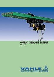
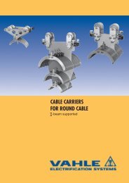
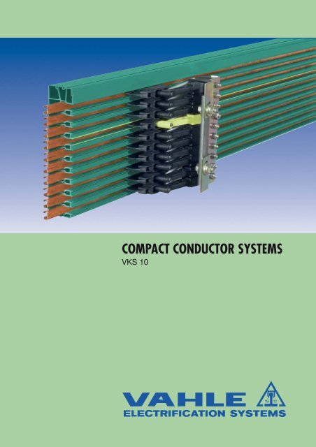
COMPACT CONDUCTOR SYSTEMS<br />
VKS 10
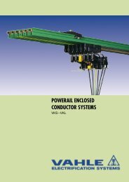
POWERAIL ENCLOSED CONDUCTORS VKS 10<br />
CONTENTS<br />
Page<br />
General 2, 3<br />
Planning guide 4<br />
Application photos 5<br />
Technical data, standard sections 6, 7<br />
Curved sections and jointing material 8<br />
Hangers 9<br />
End caps 9<br />
End feeds 9<br />
Line feeds 10<br />
Transfer funnels 11<br />
Tangential entry funnel, transfer guide and powerail isolating section 12<br />
Compact current collectors 13, 14<br />
Single current collectors 15<br />
Connecting cables 15<br />
Accessories and spare parts for current collectors 16<br />
Support profile for high bay storage 17<br />
Support profile attachments 18<br />
Positioning systems 19. 20<br />
Installation tools for VKS 10 20<br />
Questionnaire (1) 21, 22<br />
General<br />
<strong>VAHLE</strong> compact conductor system type VKS 10 are compact and<br />
shock hazard protected safety powerails. They consist of a flatformed<br />
insulated housing with integrated copper conductors.<br />
These conductors are protected according to European<br />
standard EN 60529.<br />
They comply with accident and VDE regulations in the context of<br />
electrical, mechanical and fire safety and are protected to IP 21<br />
standards. Collectors are proof against touch only when fully entered<br />
into the powerail.<br />
Powerail installations within reach of hand require a special protection<br />
on the part of the operator against accidental touch of<br />
current collectors which are leaving the powerail (e.g. locking or<br />
cut-off the power).<br />
This is only applicable for voltages above 25 V AC respectively<br />
60 V DC.<br />
The insulated housing accommodates up to 10 conductors. No<br />
special finishing work to the rail ends is necessary. The compact<br />
design allows direct mounting in runway beams and Vahle support<br />
profiles.<br />
The conductor rail is designed for indoor use only and for hanging<br />
and lateral arrangement in straight or curve systems.<br />
UL-approval<br />
Powerail electrical values: VKS 10<br />
max. continuous current = 140 A (2)<br />
Permitted operating voltage (UL) = 690 V (600 V)<br />
Dielectric strength in accord. with<br />
DIN 53481<br />
> 25 kV/mm<br />
Specific resistance in acc. with<br />
IEC 60093<br />
> 1 x 10 16 Ohm x cm<br />
Surface resistivity IEC 60093<br />
2,1 x 10 15 Ohm<br />
Leakage resistance in acc. with<br />
IEC 60112 = CTI >400<br />
Combustibility in acc. with DIN 4102, part 1: Class B1, flame<br />
retardant, self- ex<br />
tinguishing.<br />
Conductor material Copper Units<br />
Cross section 16 25 30 35 mm 2<br />
Impedance at 50 Hz (4) 1,106 0,728 0,602 0,518 Ohm/1000 m<br />
Resistance 1,102 0,723 0,595 0,510 Ohm<br />
Ampacity 60 100 120 140 (2) Amp<br />
Chemical resistance of the insulated housing<br />
Petrol, mineral oil, greases<br />
Caustic soda up to 50%<br />
Hydrochloric acid, concentrated<br />
Sulfuric acid up to 50 %<br />
UV (Xenon test >1500)<br />
Water absorption: max. at 20 °C = 0.06%<br />
resistant<br />
resistant<br />
resistant<br />
resistant<br />
resistant<br />
Ambient temperature:<br />
from -30 °C to + 55 °C (Application area)<br />
Max. temperature differences: 50 °C (50 T) (3)<br />
from -10 °C to + 40 °C with supply length = 6 m<br />
from -30 °C bis + 20 °C with supply length = 4 m (deep freeze storage (3) )<br />
Please note: When using extra-low voltages please submit<br />
detailed information with your inquiry, especially with regard<br />
to the ambient conditions.<br />
In order to process quotations and orders, we require drawings<br />
if the powerail system includes with curves or rail<br />
section isolation<br />
Please use our questionnaire on pages 18 and 19<br />
2<br />
(1)<br />
(2)<br />
(3)<br />
(4)<br />
Please submit with your inquiry!<br />
80% duty cycle<br />
Cold store applications on request<br />
By parallel circuit (doubling of cross section) is the impedance and the resistance halved.
POWERAIL ENCLOSED CONDUCTORS VKS 10<br />
VKS-10 Powerail<br />
Area of application: Indoor installation<br />
Sections:<br />
The insulated housing accommodates up to max. 10 conductors<br />
and provides reliable insulation. The standard length is 6 m, shorter<br />
lengths can be supplied. The ground conductor rail is identified<br />
with continuous yellow marking. The asymmetric design eliminates<br />
the possibility of reversing the phases during installation.<br />
One fixpoint hanger is required for each powerail<br />
section.<br />
Joints:<br />
The insulated housing sections are connected with joint caps, the<br />
conductors are joined with copper plug-in connectors.<br />
Feeds:<br />
Feed units can be supplied as end or line feeds with plastic terminal<br />
boxes or as especially flat line feeds for direct single core<br />
cable connection. Both line feed types are supplied preassembled<br />
on a 1 m powerail section.<br />
The end feeds are supplied loose and can only be used in conjunction<br />
with the VLS line feed.<br />
Current collectors:<br />
The current collectors are manufacutred from impact resistant<br />
plastic and stainless steel parts.The current is trasmitted by a<br />
carbon brush. According to the application, one or more current<br />
collectors are required per phase and ground conductor. The<br />
current collectors for the ground conductor can be identified by<br />
yellow color-coding and are equipped with different fixings to<br />
make them not-interchangeable with the phase current collectors.<br />
Springs in the current collectors ensure even pressure of the<br />
carbon brush against the conductor, thus maintaining reliable<br />
contact.<br />
The current collectors must be mounted on base plates or rectangular<br />
brackets.<br />
The length of the current collector cable should not exeed 3 m, if<br />
the connected overload protection is not according to the load of<br />
this connecting cable. See aswell DIN VDE 0100, part 430 and DIN<br />
EN 60204-32. (Note: The a.m. often occurs in systems with more<br />
collectors per system.)<br />
The connection cables provided are adequately sized for the<br />
specified nominal currents. Reduction factors in accordance with<br />
DIN VDE 0298-4 are to be taken into account for various layout<br />
methods.<br />
Electronic layout support:<br />
Please use our electronic layout software<br />
Hangers:<br />
The maximum distance between suspension points must not exceed<br />
1.2 m. The hangers are available for the following mounting<br />
options:<br />
- for assembly in <strong>VAHLE</strong> support profile (self-locking)<br />
- for assembly in c-rail (bolted type)<br />
- for assembly to plain surface (bolted type)<br />
The powerail can move with the sliding hangers for longitudinal<br />
expansion. At the fixpoint it is locked by an additional screw. The<br />
distance between two fixpoints is max. 6 m.<br />
Isolating sections:<br />
Conductor dead sections are electrical interrupts of the conductor.<br />
Under normal operating conditions a cross over with collectors<br />
to switch the voltage off or on is only allowed with low power<br />
ratings (control current).<br />
Conductor dead sections can be mounted at any position of the<br />
system. The plastic inserts are pushed into the copper profiles<br />
and ensure a smooth transfer of the collector brushes.<br />
The length of the isolating section has to consider the total length<br />
of the carbon brush and whether the carbon brush must or must<br />
not bridge the isolation area.<br />
Special attention is required for double collectors or collectors<br />
switched in parallel. Use double isolating sections where necessary.<br />
3
PLANNING GUIDE VKS 10<br />
1. System diagram<br />
L2<br />
L<br />
L1<br />
150<br />
L3<br />
end cap<br />
line feed VNS fixpoint hanger joint<br />
sliding hanger<br />
line feed VL S<br />
end feed<br />
75<br />
L = length of powerail section (standard lenght: 1 m, 2 m, 3 m, 4 m, 5 m, 6 m<br />
respectively short lenght)<br />
L 1 = distance for straight runs: max. 1.2 m<br />
in curves: max. 0.6 m<br />
= overhang (max. 300 mm)<br />
L 2<br />
L 3<br />
= distance, to be allowed for powerail expansion (min. 50 mm)<br />
2. Symbols used in installation drawing<br />
VKS 10<br />
Runway -<br />
Powerail VKS 10<br />
Joint<br />
SV<br />
Fixpoint hanger<br />
VEPS<br />
Sliding hanger<br />
VAS<br />
End cap<br />
VES<br />
End feed<br />
VEKS<br />
3. Max. hanger distance<br />
a) Powerail VKS 10<br />
-in straight runs 1.2 m<br />
-in curves<br />
0.6 m<br />
Horizontal<br />
0,6 m<br />
b) Support profile VTP 10<br />
-on rack uprights<br />
-on support posts<br />
Horizontal arrangement<br />
Attached to the wall<br />
4.5 m<br />
4.0 m<br />
3,0 m<br />
3,0 m<br />
Line feed<br />
Section isolator<br />
Transfer funnel<br />
VLS, VNS<br />
VSTS<br />
EFT- V10<br />
180 (KESR) 206 (KESR)<br />
250 (KST, KESL) 356 (KST, KESL)<br />
Arrangement 1<br />
min. 180 (KESR)<br />
min. 250 (KST, KESL)<br />
Arrangement 2<br />
min. 150<br />
Joint<br />
Line feed<br />
End feed<br />
End cap<br />
Hanger<br />
4
INSTALLATION PHOTOS VKS 10<br />
5
TECHNICAL DATA VKS 10<br />
Sections<br />
Standard lengths: 6 m<br />
Cold stores: 4 m<br />
34 (3)<br />
Left side<br />
Right side<br />
HS= with ground (PE)<br />
Attention: Joints to be ordered separately<br />
(see page 8).<br />
Max.<br />
Nominal<br />
Conductor cross section<br />
Type No. of continuous Voltage mm 2 Weight Order-No.<br />
Conductors<br />
at 35 °C<br />
L1-L3 Ground 5-10 (5)<br />
Conductor<br />
current A<br />
V<br />
material kg/m<br />
(4)<br />
VKS 10-4/ 60-6 HS 4 60 690 3 x 16 1 x 16 - Cu 2.31 780 99•<br />
VKS 10-4/100-6 HS 4 100 690 3 x 25 1 x 16 - Cu 2,54 780 71•<br />
VKS 10-4/120-6 HS 4 120 690 3 x 30 1 x 16 - Cu 2,66 780 90•<br />
VKS 10-4/140-6 HS 4 140 (1) 690 3 x 35 1 x 16 - Cu 2,79 780 68•<br />
VKS 10-5/ 60-6 HS 5 60 690 3 x 16 1 x 16 1 x 16 Cu 2,45 780 61•<br />
VKS 10-5/100-6 HS 5 100 690 3 x 25 1 x 16 1 x 16 Cu 2,69 780 70•<br />
VKS 10-5/120-6 HS 5 120 690 3 x 30 1 x 16 1 x 16 Cu 2,81 780 62•<br />
VKS 10-5/140-6 HS 5 140 (1) 690 3 x 35 1 x 16 1 x 16 Cu 2,94 780 28•<br />
VKS 10-6/ 60-6 HS 6 60 690 3 x 16 1 x 16 2 x 16 Cu 2.30 780 04•<br />
VKS 10-6/100-6 HS 6 100 690 3 x 25 1 x 16 2 x 16 Cu 2.54 780 05•<br />
VKS 10-6/120-6 HS 6 120 690 3 x 30 1 x 16 2 x 16 Cu 2.64 780 06•<br />
VKS 10-6/140-6 HS 6 140 (1) 690 3 x 35 1 x 16 2 x 16 Cu 2.81 780 07•<br />
VKS 10-7/ 60-6 HS 7 60 690 3 x 16 1 x 16 3 x 16 Cu 2.45 780 03•<br />
VKS 10-7/100-6 HS 7 100 690 3 x 25 1 x 16 3 x 16 Cu 2.68 780 08•<br />
VKS 10-7/120-6 HS 7 120 690 3 x 30 1 x 16 3 x 16 Cu 2.81 780 09•<br />
VKS 10-7/140-6 HS 7 140 (1) 690 3 x 35 1 x 16 3 x 16 Cu 2.95 780 01•<br />
VKS 10-8/ 60-6 HS 8 60 690 3 x 16 1 x 16 4 x 16 Cu 2.59 780 21•<br />
VKS 10-8/100-6 HS 8 100 690 3 x 25 1 x 16 4 x 16 Cu 2.83 780 22•<br />
VKS 10-8/120-6 HS 8 120 690 3 x 30 1 x 16 4 x 16 Cu 2.96 780 23•<br />
VKS 10-8/140-6 HS 8 140 (1) 690 3 x 35 1 x 16 4 x 16 Cu 3.09 780 24•<br />
VKS 10-9/ 60-6 HS 9 60 690 3 x 16 1 x 16 5 x 16 Cu 2.74 780 25•<br />
VKS 10-9/100-6 HS 9 100 690 3 x 25 1 x 16 5 x 16 Cu 2.97 780 26•<br />
VKS 10-9/120-6 HS 9 120 690 3 x 30 1 x 16 5 x 16 Cu 3.11 780 27•<br />
VKS 10-9/140-6 HS 9 140 (1) 690 3 x 35 1 x 16 5 x 16 Cu 3.24 780 28•<br />
VKS 10-9/200-6 HS 9 200 (2) 690 6 x 25 1 x 25 2 x 16 Cu 3.28 780 14•<br />
VKS 10-9/240-6 HS 9 240 (2) 690 6 x 30 1 x 30 2 x 16 Cu 3.60 780 13•<br />
VKS 10-9/280-6 HS 9 280 (1) (2) 690 6 x 35 1 x 35 2 x 16 Cu 3.91 780 12•<br />
VKS 10-10/ 60-6 HS 10 60 690 3 x 16 1 x 16 6 x 16 Cu 2.88 780 29•<br />
VKS 10-10/100-6 HS 10 100 690 3 x 25 1 x16 6 x 16 Cu 3.11 780 20•<br />
VKS 10-10/120-6 HS 10 120 690 3 x 30 1 x 16 6 x 16 Cu 3.25 780 30•<br />
VKS 10-10/140-6 HS 10 140 (1) 690 3 x 35 1 x 16 6 x 16 Cu 3.38 780 31•<br />
VKS 10-10/200-6 HS 10 200 (2) 690 6 x 25 1 x 25 3 x 16 Cu 3.43 780 10•<br />
VKS 10-10/240-6 HS 10 240 (2) 690 6 x 30 1 x 30 3 x 16 Cu 3.74 780 11•<br />
VKS 10-10/280-6 HS 10 280 (1) (2) 690 6 x 35 1 x 35 3 x 16 Cu 4.05 780 02•<br />
6<br />
(1)<br />
(2)<br />
(3)<br />
(4)<br />
At 80% duty cycle<br />
2 conductors per phase.<br />
Powerail projecting length 34 mm at 20 °C ambient.<br />
Consult factory in case of circuits incl. N conductors.<br />
(5)<br />
Not with UL-approval; UUL= 600 V<br />
• Supplement type designations, e.g. 2 m VKS 10-6/60 with PE (ground)<br />
VKS 10-6/60 - 2 HS Order-No. 780042.<br />
Short lengths will be produced out of the next larger rail section.
STANDARD SECTIONS VKS 10<br />
Right side<br />
Left side<br />
168<br />
160<br />
Ø 15,3<br />
130<br />
80<br />
9 x 14 = 126 24,5<br />
VKS 10-4/ 60-140 VKS 10-5/ 60-140 VKS 10-6/ 60-140 VKS 10-7/ 60-140 VKS 10-8/ 60-140<br />
L1 L1 L1 L1 L1<br />
L2 L2 L2 L2 L2<br />
L3 L3 L3 L3 L3<br />
PE (ground) PE (ground) PE (ground) PE (ground) PE (ground)<br />
Free 5 5 5 5<br />
Free Free 6 6 6<br />
Free Free Free 7 7<br />
Free Free Free Free 8<br />
Free Free Free Free Free<br />
Free Free Free Free Free<br />
6,5 24,5<br />
37<br />
168<br />
160<br />
Ø 15,3<br />
130<br />
80<br />
9 x 14 = 126 24,5<br />
VKS 10-9/ 60-140 VKS 10-9/200-280 VKS 10-10/ 60-140 VKS 10-10/200-280<br />
L1 L1 L1 L1<br />
L2 L2 L2 L2<br />
L3 L3 L3 L3<br />
PE (ground) PE (ground) PE (ground) PE (ground)<br />
5 L1 5 L1<br />
6 L2 6 L2<br />
7 L3 7 L3<br />
8 8 8 8<br />
9 9 9 9<br />
Free Free 10 10<br />
6,5 24,5<br />
37<br />
7
CURVED SECTIONS AND JOINTS VKS 10<br />
Curved sections<br />
vertical in accordance with your design drawings<br />
Copper cross section min. 25 mm 2<br />
Max. length of bend = 5.3 m<br />
Hanger distance 0.6 m<br />
Max. angle = 180°<br />
Inside bend = conductors inside<br />
Outside bend = conductors outside<br />
(not shown)<br />
Inside bend R Outside bend R<br />
Bends are supplied with straight ends, each 250 mm long.<br />
Type R mm (2) Order-No.<br />
Inside bend (as shown) 1000 780 344<br />
Outside bend 1500 780 345<br />
Joints (3)<br />
150<br />
Plug-in joint<br />
for 140 A<br />
Plug-in joint<br />
for 10-60 A and 100- 120 A<br />
Type<br />
No. of poles<br />
Weight kg<br />
Order-No.<br />
SV 10- 4/ 60 4 0,165 781 321<br />
SV 10- 4/100-120 4 0,165 781 322<br />
SV 10- 4/140 4 0,344 781 323<br />
SV 10- 5/ 60 5 0,385 781 315<br />
SV 10- 5/100-120 5 0,385 781 320<br />
SV 10- 5/140 5 0,366 781 277<br />
SV 10- 6/ 60 6 0,407 781 150<br />
SV 10- 6/100-120 6 0,407 781 151<br />
SV 10- 6/140 6 0,388 781 152<br />
SV 10- 7/ 60 7 0,429 781 153<br />
SV 10- 7/100-120 7 0,429 781 154<br />
SV 10- 7/140 7 0,410 781 155<br />
SV 10- 8/ 60 8 0,451 781 156<br />
SV 10- 8/100-120 8 0,451 781 157<br />
SV 10- 8/140 8 0,432 781 158<br />
SV 10- 9/ 60 9 0,473 781 159<br />
SV 10- 9/100-120 9 0,473 781 160<br />
SV 10- 9/140 9 0,454 781 161<br />
SV 10- 9/200-240 (1) 9 0,473 781 162<br />
SV 10- 9/280 (1) 9 0,423 781 163<br />
SV 10-10/ 60 10 0,495 781 164<br />
SV 10-10/100-120 10 0,495 781 165<br />
SV 10-10/140 10 0,476 781 166<br />
SV 10-10/200-240 (1) 10 0,495 781 167<br />
SV 10- 10/280 (1) 10 0,450 781 168<br />
8<br />
(1)<br />
Conductor rails connected in parallel<br />
(2)<br />
Smaller radius on request<br />
3)<br />
In case of hall expansion joints please consider expansion sections (on request).
FIXPOINT HANGERS, SLIDING HANGERS, END CAPS,<br />
END FEEDS VKS 10<br />
Fixpoint hanger on C-rail<br />
consisting of hanger clamp and fixing screw and C-rail<br />
Sliding hanger on C-rail<br />
consisting of hanger clamp and C-rail<br />
Fixing screw<br />
C-rail 28/15<br />
200<br />
Type Weight kg Order-No.<br />
VEPS 10-H 0.224 780 007<br />
Type Weight kg Order-No.<br />
VAS 10-H 0.223 780 008<br />
Fixpoint hanger for support profile VTP 10<br />
consisting of hanger and fixing screw<br />
Ø14<br />
Fixing screw<br />
130<br />
30<br />
Support profile<br />
Type Weight kg Order-No.<br />
VEPS 10-VTP 0.033 780 009<br />
Type Weight kg Order-No.<br />
VAS 10-VTP 0.032 780 010<br />
End cap<br />
Can be used right or left handed.<br />
Supplied loose as individual part with fixing screws.<br />
End feed (1)<br />
Terminal box supplied loose,<br />
only in conjunction with line feed VLS (2)<br />
80<br />
167<br />
200<br />
168<br />
130<br />
80<br />
6,5<br />
37<br />
43,5<br />
Sliding hanger for support profile VTP 10<br />
consisting of hanger clamp<br />
240<br />
168<br />
130<br />
56,5<br />
27,5<br />
1,5<br />
46,5<br />
116 length<br />
length<br />
37<br />
5<br />
230<br />
Type Weight kg Order-No.<br />
VES 10 L 0.210 780 004<br />
Type Weight kg Order-No.<br />
VEKS 10-10/ 60-280 0.664 780 018<br />
(1)<br />
(2)<br />
Cable glands, 2 x ST-M 40 x 1.5 for D = 19-28 mm<br />
1 x ST-M 20 x 1.5 for D = 7-13 mm<br />
Please order VLS line feed separately.<br />
9
2 0 0<br />
LINE FEED VKS 10<br />
Line feed VLS<br />
for direct connection of single core cables<br />
M6 terminal with special cable shoe for single core cables;<br />
35 mm 2 (up to cable Ø 8.5 mm) for 140 A,<br />
25 mm 2 (up to cable Ø 8.2 mm) for 100 A - 120 A,<br />
or feed bolts for 60 A powerail<br />
1 m section to be ordered separately.<br />
right side<br />
length<br />
1m<br />
250 (350 (1) )<br />
left side<br />
Type<br />
No. of<br />
conductors<br />
Current<br />
capacity A<br />
Weight<br />
kg<br />
Order-No.<br />
VLS 10- 4/ 60 4 60 0,217 781 445<br />
VLS 10- 4/100-120 4 100-120 0,382 781 479<br />
VLS 10- 4/140 4 140 0,574 781 478<br />
VLS 10- 5/ 60 5 60 0,230 780 610<br />
VLS 10- 5/100-120 5 100-120 0,426 780 759<br />
VLS 10- 5/140 5 140 0,630 780 745<br />
VLS 10- 6/ 60 6 60 0,217 780 047<br />
VLS 10- 6/100-120 6 100-120 0,382 780 060<br />
VLS 10- 6/140 6 140 0,574 780 187<br />
VLS 10- 7/ 60 7 60 0,230 780 049<br />
VLS 10- 7/100-120 7 100-120 0,426 780 188<br />
VLS 10- 7/140 7 140 0,630 780 189<br />
VLS 10- 8/ 60 8 60 0,243 780 050<br />
VLS 10- 8/100-120 8 100-120 0,470 780 196<br />
VLS 10- 8/140 8 140 0,686 780 198<br />
VLS 10- 9/ 60 9 60 0,256 780 058<br />
VLS 10- 9/100-120 9 100-120 0,514 780 199<br />
VLS 10- 9/140 9 140 0,742 780 191<br />
VLS 10- 9/200-240 (1) 9 200-240 0,744 780 322<br />
VLS 10- 9/280 (1) 9 280 0,828 780 321<br />
VLS 10-10/ 60 10 60 0,269 780 059<br />
VLS 10-10/100-120 10 100-120 0,558 780 192<br />
VLS 10-10/140 10 140 0,798 780 208<br />
VLS 10-10/200-240 (1) 10 200-240 0,757 780 318<br />
VLS 10-10/280 (1) 10 280 0,815 780 317<br />
Opening for cable outlet<br />
Cable outlet double-sided<br />
Line feed VNS<br />
with terminal box<br />
Cable gland: STR - M 63 x 1,5 for Ø = 28-45<br />
STR - M 20 x 1,5 for Ø = 5-13<br />
Connection cable to be supplied by customer<br />
Cable connection: Main current: M10<br />
Control current: M 5<br />
1 m section to be ordered separately.<br />
right side<br />
3 6 0<br />
left side<br />
Type<br />
No. of<br />
poles<br />
Current<br />
capacity A<br />
Weight<br />
kg<br />
Order-No.<br />
VNS 10- 4/ 60-140 4 60-140 2,354 780 527<br />
VNS 10- 5/ 60-140 5 60-140 2,580 780 537<br />
VNS 10- 6/ 60-140 6 60-140 2,766 780 327<br />
VNS 10- 7/ 60-140 7 60-140 2,952 780 328<br />
VNS 10- 8/ 60-140 8 60-140 3,138 780 329<br />
1 5 0<br />
VNS 10- 9/ 60-140 9 60-140 3,324 780 330<br />
VNS 10- 9/200-280 9 200-280 2,840 780 334<br />
1 m<br />
VNS 10-10/ 60-140 10 60-140 3,510 780 331<br />
VNS 10-10/200-280 10 200-280 2,865 780 332<br />
Cable payout left, standard<br />
10<br />
(1)<br />
Length of the cap
TRANSFER FUNNELS VKS 10<br />
Transfer funnel (1) for current collector KESL 32-63/14<br />
max. speed v= 100 m/min.<br />
Conductor rails for funnels (all cross<br />
sections 25 mm 2 , length 1365 mm)<br />
Type Order-No.<br />
No. of conductors 4 781 442<br />
No. of conductors 5 780 743<br />
No. of conductors 6 780 247<br />
No. of conductors 7 780 248<br />
No. of conductors 8 780 249<br />
No. of conductors 9 780 250<br />
No. of conductors 10 780 257<br />
Tolerances:<br />
x = ± 10 mm<br />
y = ± 10 mm<br />
X<br />
Y<br />
Y<br />
X<br />
90<br />
775<br />
Auxiliary support and fixing claw<br />
to be ordered seperately<br />
600<br />
End cap to order<br />
seperately<br />
82<br />
94,5<br />
146<br />
9,4°<br />
Powerail VKS 10<br />
to be ordered seperately<br />
Type see table above<br />
125<br />
85<br />
65<br />
Support profile<br />
1365<br />
650<br />
200<br />
R<br />
6,5 B<br />
C<br />
D<br />
A<br />
6,5<br />
Type<br />
No.ofconductors<br />
A<br />
mm<br />
B<br />
mm<br />
C<br />
mm<br />
D<br />
mm<br />
Weight<br />
kg<br />
Order-No.<br />
EFTV 10- 4-KSTU 30/63 -14 L 4 14 42 55 109 7,594 781 441<br />
EFTV 10- 4-KSTU 30/63 -14 R 4 14 42 55 109 7,594 781 440<br />
EFTV 10- 5-KSTU 30/63 -14 L 5 14 56 69 123 7,584 780 746<br />
EFTV 10- 5-KSTU 30/63 -14 R 5 14 56 69 123 7,584 780 747<br />
EFTV 10- 6-KSTU 30/63 -14 L 6 14 70 83 137 7,574 780 350<br />
EFTV 10- 6-KSTU 30/63 -14 R 6 14 70 83 137 7,574 780 173<br />
EFTV 10- 7-KSTU 30/63 -14 L 7 14 84 97 151 7,564 780 349<br />
EFTV 10- 7-KSTU 30/63 -14 R 7 14 84 97 151 7,564 780 172<br />
EFTV 10- 8-KSTU 30/63 -14 L 8 14 98 111 165 7,554 780 348<br />
EFTV 10- 8-KSTU 30/63 -14 R 8 14 98 111 165 7,554 780 171<br />
EFTV 10- 9-KSTU 30/63 -14 L 9 14 112 125 179 7,544 780 347<br />
EFTV 10- 9-KSTU 30/63 -14 R 9 14 112 125 179 7,544 780 170<br />
EFTV 10-10-KSTU 30/63 -14 L 10 14 126 139 193 7,534 780 346<br />
EFTV 10-10-KSTU 30/63 -14 R 10 14 126 139 193 7,534 780 169<br />
(1)<br />
Transfer funnel only in combination with powerail section. Higher speeds on request.<br />
11
-A-<br />
TANGENTIAL ENTRY FUNNEL,<br />
POWERAIL SECTION ISOLATION VKS 10<br />
Tangential entry funnel for collector KSTU 30 - 55<br />
max. entry speed v = 100 m/min. Copper cross section min. 25 mm 2<br />
92<br />
47<br />
Tolerances:<br />
x = ± 10 mm<br />
y = +8 mm, -7 mm<br />
Y<br />
186<br />
X<br />
X<br />
Y<br />
500<br />
61<br />
Type No. of poles A Weight kg Order-No.<br />
DSEV 10- 4 KSTU 30-63 4 56,5 1,888 781 453<br />
DSEV 10- 5 KSTU 30-63 5 70,5 1,884 781 452<br />
DSEV 10- 6 KSTU 30-63 6 84,5 1,880 780 168<br />
DSEV 10- 7 KSTU 30-63 7 98,5 1,876 780 167<br />
DSEV 10- 8 KSTU 30-63 8 112,5 1,872 780 166<br />
DSEV 10- 9 KSTU 30-63 9 126,5 1,868 780 165<br />
DSEV 10-10 KSTU 30-63 10 140,5 1,575 780 164<br />
Transfer guide VU 10<br />
14<br />
Type Assignment from top Order-No.<br />
30 (2)<br />
For cross travel and terminal lines<br />
max. height- and lateral off-set: ± 2 mm<br />
max. air gap between the transfer guides: 5 mm<br />
VU 10-4 L Schiene 1- 4 781 456<br />
VU 10-4 R Schiene 1- 4 781 457<br />
VU 10-5 L Schiene 1- 5 781 458<br />
VU 10-5 L Schiene 1- 5 781 459<br />
VU 10-6 L rail 1- 6 780 287<br />
VU 10-6 R rail 1- 6 780 288<br />
VU 10-7 L rail 1- 7 780 227<br />
VU 10-7 R rail 1- 7 780 228<br />
VU 10-8 L rail 1- 8 780 229<br />
VU 10-8 R rail 1- 8 780 230<br />
VU 10-9 L rail 1- 9 780 289<br />
VU 10-9 R rail 1- 9 780 290<br />
VU 10-10 L rail 1-10 780 269<br />
VU 10-10 R rail 1-10 780 270<br />
Powerail isolating section (1)<br />
The position of the isolating sections are to be identified in the order.<br />
30 (2)<br />
Type Weight kg Order-No.<br />
VSTS 1/10-60 M 0,004 156 933<br />
VSTS 1/ 100 M 0,004 150 150<br />
VSTS 1/ 120 M 0,004 151 674<br />
VSTS 1/ 140 M 0,004 156 335<br />
M = factory assembled; L = supplied loose<br />
12<br />
(1)<br />
(2)<br />
For specification of the powerail profile see page 6<br />
Length of the conductor dead section (longer dead sections on request).
CURRENT COLLECTOR VKS 10<br />
Compact current collector KESR 32/55 for reverse run<br />
Distance between conductors:<br />
14 mm<br />
14<br />
148<br />
max. current flat plug bolted connection<br />
32 A FLA 2,5 AEA 2,5<br />
40 A FLA 4,0 AEA 4,0<br />
55 A FLA 6,0 AEA 6,0<br />
Lift and swivel ± 15 mm<br />
Contact pressure: approx. 3.5 N per carbon brush<br />
PE (ground) on No. 4, other combinations possible<br />
The ground collector always moves first when entering<br />
the powerail.<br />
KESR-F<br />
for connecting cables with flat plug see table 1 page 16<br />
Flat plug<br />
6,3 x 0,8<br />
for FLA<br />
or<br />
bolted<br />
connection<br />
88<br />
10<br />
9 8 7 6 5 4 3 2 1<br />
b<br />
a<br />
c<br />
15<br />
RF3<br />
DF2<br />
7 42 15<br />
max. 12<br />
72<br />
Type No. of poles a mm b mm c mm Weight kg Baseplate Order-No.<br />
KESR 32-55 F 4-14 HS 4 28 62 - 0,480 4-pole 143 170<br />
KESR 32-55 F 5-14 HS 5 56 90 - 0,540 6-pole 143 373<br />
KESR 32-55 F 6-14 HS 6 56 90 - 0,600 6 pole 143 113<br />
KESR 32-55 F 7-14 HS 7 80 118 53 0,660 8 pole (no. 8= free) 143 114<br />
KESR 32-55 F 8-14 HS 8 80 118 53 0,720 8 pole 143 115<br />
KESR 32-55 F 9-14 HS 9 80 146 53 0,780 10 pole (no. 10= free) 143 116<br />
KESR 32-55 F 10-14 HS 10 80 146 53 0,840 10 pole 143 117<br />
Single collector: Phase PE (ground)<br />
Current collector KESR 32-55 F 14 0,060 143 111 143 112<br />
KESR-S<br />
for connecting cables with bolted connection see table 2 page 16<br />
Type No. of poles a mm b mm c mm Weight kg Baseplate Order-No.<br />
KESR 32-55 S 4-14 HS 4 28 62 - 0,504 4-pole 142 937<br />
KESR 32-55 S 5-14 HS 5 56 90 - 0,570 6-pole 142 938<br />
KESR 32-55 S 6-14 HS 6 56 90 - 0,636 6 pole 142 939<br />
KESR 32-55 S 7-14 HS 7 80 118 53 0,702 8 pole (no. 8= free) 142 940<br />
KESR 32-55 S 8-14 HS 8 80 118 53 0,768 8 pole 142 941<br />
KESR 32-55 S 9-14 HS 9 80 146 53 0,834 10 pole (no. 10= free) 142 942<br />
KESR 32-55 S 10-14 HS 10 80 146 53 0,890 10 pole 142 943<br />
Single collector: Phase PE (ground)<br />
Current collector KESR 32-63 S/14 (1) 0,066 143 120 143 121<br />
Compact current collector KESR 63 S for reverse run with adapter plate and clamping block.<br />
1 2 3 4 5 6 7 8 9 10<br />
133<br />
Spare parts<br />
Type Order-No.<br />
Carbon MK 63 S/14.28 780 921<br />
Current collector KESR 32-63 S/14 PE 143 121<br />
Current collector KESR 32-63 S/14 PH 143 120<br />
Left hand version<br />
Ground on No.4<br />
Type No. of poles Configuration Order-No.<br />
KESR 63 S- 4-14 HS- KBL 4 1- 4 781 089<br />
KESR 63 S- 5-14 HS- KBL 5 1- 6 781 088<br />
KESR 63 S- 6-14 HS- KBL 6 1- 6 781 087<br />
KESR 63 S- 7-14 HS- KBL 7 1- 7 781 086<br />
KESR 63 S- 8-14 HS- KBL 8 1- 8 781 085<br />
KESR 63 S- 9-14 HS- KBL 9 1- 9 781 084<br />
KESR 63 S-10-14 HS- KBL 10 1-10 781 083<br />
Right hand version<br />
Ground on No. 7<br />
torque setting:<br />
1,7 Nm (2)<br />
(bolted<br />
connection)<br />
180<br />
9 x 20<br />
109,5<br />
Type No. of poles Configuration Order-No.<br />
KESR 63 S- 4-14 HS- KBR 4 7-10 781 096<br />
KESR 63 S- 5-14 HS- KBR 5 6-10 781 095<br />
KESR 63 S- 6-14 HS- KBR 6 5-10 781 094<br />
KESR 63 S- 7-14 HS- KBR 7 4-10 781 093<br />
KESR 63 S- 8-14 HS- KBR 8 3-10 781 092<br />
KESR 63 S- 9-14 HS- KBR 9 2-10 781 091<br />
KESR 63 S-10-14 HS- KBR 10 1-10 781 090<br />
62<br />
(1)<br />
(2)<br />
Only in combination with clamping block and 10 mm 2 connecting cable.<br />
Max. cross section of connecting cable 16 mm² (UL = 10 mm 2 ).<br />
13
150<br />
CURRENT COLLECTOR VKS 10<br />
Compact current collector KESL 32-63 for reverse run<br />
Distance between conductors:<br />
14 mm<br />
max. current flat plug bolted connection<br />
32 A FLA 2,5 AEA 2,5<br />
40 A FLA 4,0 AEA 4,0<br />
55 A FLA 6,0 AEA 6,0<br />
63 A - AEA 10,0<br />
Lift and swivel ± 30 mm<br />
Contact pressure: approx. 7 N per carbon brush<br />
PE (ground) on no. 4, other combinations possible<br />
The ground collector always moves first when entering<br />
the powerail.<br />
14<br />
105<br />
10 9 8 76 5 43 2 RF3<br />
1<br />
Flat<br />
plug<br />
6,3 x 0,8<br />
for FLA<br />
or bolted<br />
connection<br />
b<br />
a<br />
c<br />
224<br />
15<br />
DF4<br />
max. 12<br />
7 42 15<br />
72<br />
KESL-F<br />
for connecting cables with flat plug see table 1 page 16<br />
Type No. of poles a mm b mm c mm Weight kg Baseplate Order-No.<br />
KESL 32-55 F 4-14 HS 4 28 62 - 0,536 4-pole 143 152<br />
KESL 32-55 F 5-14 HS 5 56 90 - 0,612 6-pole 781 257<br />
KESL 32-55 F 6-14 HS 6 56 90 - 0,688 6 pole 142 883<br />
KESL 32-55 F 7-14 HS 7 80 118 53 0,764 8 pole (no. 8= free) 142 884<br />
KESL 32-55 F 8-14 HS 8 80 118 53 0,840 8 pole 142 885<br />
KESL 32-55 F 9-14 HS 9 80 146 53 0,916 10 pole (no. 10= free) 142 886<br />
KESL 32-55 F 10-14 HS 10 80 146 53 0,992 10 pole 142 887<br />
Single collector: Phase PE (ground)<br />
Current collector KESL 32-55 F/14 0,076 142 881 142 882<br />
KESL-S<br />
for connecting cables with bolted connection see table 2 page 16<br />
Type No. of poles a mm b mm c mm Weight kg Baseplate Order-No.<br />
KESL 32-63 S 4-14 HS 4 28 62 - 0,553 4-pole 143 539<br />
KESL 32-63 S 5-14 HS 5 56 90 - 0,637 6-pole 143 354<br />
KESL 32-63 S 6-14 HS 6 56 90 - 0,721 6 pole 142 888<br />
KESL 32-63 S 7-14 HS 7 80 118 53 0,803 8 pole (no. 8= free) 142 889<br />
KESL 32-63 S 8-14 HS 8 80 118 53 0,885 8 pole 142 890<br />
KESL 32-63 S 9-14 HS 9 80 146 53 0,967 10 pole (no. 10= free) 142 891<br />
KESL 32-63 S 10-14 HS 10 80 146 53 1,049 10 pole 142 892<br />
Single collector: Phase PE (ground)<br />
Current collector KESL 32-63 S/14 0,084 168 395 142 880<br />
Compact current collector KESL 63 S for reverse run<br />
with adapter plate and clamping block.<br />
1 2 3 4 56 7 8 9 10<br />
left hand version<br />
Spare parts<br />
Type Order-No.<br />
Carbon MK 63 S/14.28 780 921<br />
Current collector KESL 32-63 S/14 PE 142 880<br />
Current collector KESL 32-63 S/14 PH 168 395<br />
Left hand version<br />
Ground on No.4<br />
Type No. of poles Configuration Order-No.<br />
KESL 63 S- 4-14 HS- KBL 4 1- 4 781 075<br />
KESL 63 S- 5-14 HS- KBL 5 1- 5 781 074<br />
KESL 63 S- 6-14 HS- KBL 6 1- 6 781 073<br />
KESL 63 S- 7-14 HS- KBL 7 1- 7 781 072<br />
KESL 63 S- 8-14 HS- KBL 8 1- 8 781 071<br />
KESL 63 S- 9-14 HS- KBL 9 1- 9 781 070<br />
KESL 63 S-10-14 HS- KBL 10 1-10 781 069<br />
torque setting:<br />
1,7 Nm (1) (bolted<br />
connection)<br />
Right hand version<br />
Ground on No. 7<br />
180<br />
9 x 20<br />
62<br />
109,5<br />
Type No. of poles Configuration Order-No.<br />
KESL 63 S- 4-14 HS- KBR 4 3-10 781 082<br />
KESL 63 S- 5-14 HS- KBR 5 4-10 781 081<br />
KESL 63 S- 6-14 HS- KBR 6 5-10 781 080<br />
KESL 63 S- 7-14 HS- KBR 7 4-10 781 079<br />
KESL 63 S- 8-14 HS- KBR 8 3-10 781 078<br />
KESL 63 S- 9-14 HS- KBR 9 2-10 781 077<br />
KESL 63 S-10-14 HS- KBR 10 1-10 781 076<br />
14<br />
(1)<br />
Max. cross section of connecting cable 16 mm² (UL = 10 mm 2 ).
CURRENT COLLECTOR VKS 10, CONNECTING CABLES<br />
Current collector KST<br />
Current collector KSTU<br />
for funnels and tangential entry funnels (multi systems)<br />
85<br />
60<br />
140<br />
13,5<br />
4,4<br />
85<br />
32,2<br />
12<br />
With 2 m connecting cables<br />
Lift and swivel: see following table<br />
Contact pressure: approx. 5 N<br />
With 2 m connecting cables<br />
Lift and swivel see Table<br />
(in funnels 10 mm to all sides)<br />
Contact pressure: approx. 5 N<br />
Current Connection cable Lift+<br />
Order-No.<br />
Current Connection cable Lift + Order-No.<br />
Type capacity A/ d max./ swivel Weight Phase (ground) Type capacity A/ d max./ swivel Weight Phase (ground)<br />
A<br />
mm 2 mm mm kg black yellow<br />
A mm 2 mm mm kg black yellow<br />
KST 30 30 2,50 5 ± 20 0,240 152 085 152 086<br />
KST 55 55 6,00 11 ± 20 0,368 154 438 154 439<br />
KST 63 63 10,00 9 ± 20 0,394 156 791 156 792<br />
KSTU 30/14 30 2,50 5 ± 20 0,240 168 363 168 364<br />
KSTU 55/14 55 6,00 11 ± 20 0,368 168 361 168 362<br />
KSTU 63/14 63 10,00 9 ± 20 0,394 148 018 148 019<br />
Connecting cable FLA (1) , highly flexible, for current collectors.<br />
(For allocation to current collectors see page 13 and 14)<br />
Connecting cable AEA (1) ,<br />
highly flexible for current collectors<br />
FH<br />
FLA<br />
Length = 1 m with flat plug 6,3 x 0,8<br />
Longer connecting length available.<br />
Length: 1 m<br />
Longer connecting length available.<br />
Table 1 Table 2<br />
Type<br />
Cross section Outside Ø<br />
Order-No.<br />
Weight<br />
Cross section Outside Ø Weight<br />
Order-No..<br />
mm 2 mm kg Phase PE<br />
Type mm<br />
black green/yellow<br />
mm kg Phase PE<br />
black green/yellow<br />
FLA 2,5 2,50 4,00 0,080 165 049 165 050<br />
AEA 2,5 2,50 4,00 0,038 143 080 143 079<br />
FLA 4 4,00 6,00 0,100 165 051 165 052<br />
AEA 4,0 4,00 5,50 0,063 143 078 143 077<br />
FLA 6 6,00 7,00 0,150 166 368 166 369<br />
AEA 6,0 6,00 6,00 0,085 143 076 143 075<br />
AEA 10,0 10,00 8,50 0,160 143 074 143 073<br />
Flat plug, single<br />
Type<br />
for cable cross section<br />
Order-No.<br />
mm 2<br />
FH 2,5 2,50 165 120<br />
FH 4-6 4,00 + 6,00 165 121<br />
FH 2,5 FH 4,0-6,0<br />
(1)<br />
Application area: -15 °C to + 70 °C.<br />
15
ACCESSORIES FOR CURRENT COLLECTORS VKS 10<br />
Collector bracket<br />
for current collectors<br />
KST 30-55 see page 15<br />
Carbon brushes<br />
KMK 30-55 PH<br />
75<br />
60<br />
RH<br />
76<br />
with ground<br />
60<br />
23<br />
10<br />
Ground-marking<br />
KMK 30-55 PE<br />
Design „R“ shown<br />
10<br />
RH<br />
Type A<br />
mm<br />
B<br />
mm<br />
C<br />
mm<br />
Weight kg Order-No.<br />
UMA 12 HS-B- 4-14 L 80 20 50 0,33 781 444<br />
UMA 12 HS-B- 4-14 R 80 20 50 0,33 781 443<br />
UMA 12 HS-B- 5-14 L 94 34 50 0,36 780 186<br />
UMA 12 HS-B- 5-14 R 94 34 50 0,36 780 185<br />
UMA 12 HS-B- 6-14 L 108 48 50 0.39 780 184<br />
UMA 12 HS-B- 6-14 R 108 48 50 0.39 780 183<br />
UMA 12 HS-B- 7-14 122 62 50 0.42 780 181<br />
UMA 12 HS-B- 8-14 L 136 76 50 0.46 780 180<br />
UMA 12 HS-B- 8-14 R 136 76 50 0.46 780 179<br />
UMA 12 HS-B- 9-14 L 150 90 50 0.49 780 178<br />
UMA 12 HS-B- 9-14 R 150 90 50 0.49 780 177<br />
UMA 12 HS-B-10-14 L 164 104 50 0.52 780 176<br />
UMA 12 HS-B-10-14 R 164 104 50 0,52 780 175<br />
Type<br />
51<br />
For<br />
current collector<br />
KST 30 - KST 63<br />
and KSTU 30 - 63<br />
Carbon brush<br />
thickness<br />
MK 55 PH / PE<br />
MK 63 PH / PE<br />
RH<br />
mm<br />
Weight<br />
kg<br />
Order-<br />
No.<br />
KMK 30-55 PH 4,40 mm 4,00 0,031 154 440<br />
KMK 30-55 PE KST 30 - KST 63<br />
and KSTU 30 - 63 4,40 mm 4,00 0,031 154 453<br />
MK 55 F/14.28<br />
KESR 32 - 55F<br />
KESL 32 - 55F 4,20 mm 3,50 0,040 780 920<br />
MK 63 S/14.28<br />
KESR 32 - 63S<br />
KESL 32 - 63S 4,20 mm 3,50 0,046 780 921<br />
Springs<br />
Pressure spring DF<br />
Tension spring RF<br />
Type<br />
For current collector<br />
S D L<br />
mm mm mm<br />
Order-No.<br />
DF 2 KESR 32-55 0.90 7.70 43.00 153 848<br />
RF 3 KESR 32-55 0.40 4.40 31.00 153 849<br />
DF 4 KESL 32-63 1,10 6,40 41,00 157 312<br />
16
SUPPORT PROFILE FOR HIGH BAY STORAGE VKS 10<br />
Accessories VKS 10<br />
Type<br />
Order-No.<br />
Connector cap 780 137<br />
Plug-in joint VKS 10/ 10- 60A 780 807<br />
Plug-in joint VKS 10/ 100-120 A 780 808<br />
Plug-in joint VKS 10/ 140 A 780 028<br />
Connection bolts, complete for VLS 10/ 60 + 200-280 780 138<br />
Connection bolts, complete for VLS 10/100-140 780 130<br />
Connection bolts, complete for VNS 10/ 60-280 780 139<br />
Plastik glue for tangential funnel DSEV 10 780 280<br />
Support profile<br />
Length: 6 m<br />
200<br />
56,5<br />
240<br />
Type Weight kg/m Order-No.<br />
VTP 10 4,300 781 006<br />
46,5<br />
Ø14<br />
Support profile VTP 10 for feed VNS 10, VLS 10<br />
Support profile<br />
600<br />
1200<br />
1050 150<br />
300<br />
Type<br />
Order-No.<br />
Version for initial / end section 780 100<br />
Version on the track 780 098<br />
Terminal box not included<br />
not applicable on the track<br />
Connector<br />
Only as single component otherwise included in the attachment<br />
material of the support profile (see page 18).<br />
Hanger<br />
Only as single component otherwise included in the attachment<br />
material of the support profile (see page 18).<br />
360<br />
130<br />
11 x 35<br />
192<br />
11 x 35<br />
192<br />
9 x 30<br />
9 x 30<br />
Type Weight kg Order-No.<br />
VTPV 10 2.398 781 000<br />
Type Weight kg Order-No.<br />
VTPA 10 0.878 781 007<br />
17
SUPPORT PROFILE ATTACHMENTS VKS 10<br />
VTPB-P<br />
Fig. 1<br />
x<br />
VTPB<br />
Fig. 4<br />
x<br />
VTPB-SPR<br />
Fig. 2<br />
max. 15<br />
35-165<br />
Klemmbereich<br />
Fixing claw<br />
75<br />
Rack upright<br />
35<br />
max. 285<br />
360<br />
130<br />
(2)<br />
VTPB-SPW Fig. 3<br />
View x<br />
View y<br />
Clamping profile<br />
M10<br />
max. 50<br />
130<br />
M10<br />
30<br />
M10<br />
30<br />
M10<br />
195<br />
80-170<br />
360<br />
max. 8<br />
VTPB-S 1/2 Fig. 5<br />
S1, S2<br />
25<br />
130<br />
Type (1) Fig. Clamping range Weight kg Order-No.<br />
VTPB-P 1 max. 8 0,938 780 147<br />
VTPB-SPR 2 max. 15 2,674 780 149<br />
VTPB 130-SPW 3 max. 15 1,066 780 148<br />
VTPB 35 - 45 4 35 - 45 3,054 780 150<br />
VTPB 45 - 55 4 45 - 55 3,062 780 151<br />
VTPB 55 - 65 4 55 - 65 3,076 780 152<br />
VTPB 65 - 75 4 65 - 75 3,084 780 153<br />
VTPB 75 - 85 4 75 - 85 3,096 780 154<br />
VTPB 85 - 95 4 85 - 95 3,102 780 155<br />
VTPB 90 - 105 4 90 - 105 3,110 780 156<br />
VTPB 100 -115 4 100 - 115 3,118 780 157<br />
VTPB 110 - 125 4 110 - 125 3,132 780 158<br />
VTPB 120 - 135 4 120 - 135 3,144 780 159<br />
VTPB 130 - 145 4 130 - 145 3,152 780 160<br />
VTPB 140 - 155 4 140 - 155 3,164 780 161<br />
VTPB 150 - 165 4 150 - 165 3,172 780 162<br />
VTPB S 1/2 5 max.8 0,944 780 163<br />
18<br />
(1)<br />
(2)<br />
Bigger clamping range on request.<br />
Locking torque of the round-head screw M 10, MA= 18 Nm
<strong>VAHLE</strong>-APOS ® POSITIONING SYSTEM<br />
Operating principle<br />
<strong>VAHLE</strong>-APOS ® consists of a code strip with magnetic length coding and a reading head with integrated logic,<br />
which transmits the position to the control system via interface. The intelligent reading head determines the<br />
position from the code strip and evaluates it for downstream control systems for processing.<br />
<strong>VAHLE</strong>-APOS ®<br />
in VKS 10 - 10. pole<br />
<strong>VAHLE</strong>-APOS ®<br />
in VKS 10 - 11. pole<br />
• absolute positioning identification upto 524 m<br />
• retrofit<br />
• absolute position at engaging or after a outage directly<br />
available<br />
• safe position identification aswell with wetness or dust<br />
• travel speed upto 6 m/s<br />
For further details please refer to <strong>VAHLE</strong>-APOS ® catalog (7a)<br />
19
POSITIONING SYSTEM<br />
Cost-efficient installation of different positioning systems<br />
position encoding<br />
system (WCS)<br />
position encoding system<br />
(BCB)<br />
fixing clip<br />
(see below)<br />
position encoding system (WCS)<br />
at lateral arrangement<br />
position encoding system<br />
(WCS 3) with seperate<br />
Aluminium-Profile.<br />
(drilling by others)<br />
Earthing of the code rail:<br />
Connect the WCS code rail at least every 30 m to the potential of the system of low resistance.<br />
(Part-No.: E- WCS 3/VTP 10/ 302 160).<br />
Fixing clip<br />
for laminate band<br />
Position<br />
encoding band<br />
Fixing distance 0.2 m<br />
WCS (1)<br />
1x per conductor<br />
section<br />
BCB(2)<br />
Type Weight kg Order-No.<br />
Fixing clip<br />
for plastic laminate band<br />
0,002 780 193<br />
Type Weight kg/m Order-No.<br />
Plastic laminate band<br />
with special perforation (WCS 3)<br />
0,040 302 106<br />
Screws for fixation 0,001 780 140<br />
Barcode band (BCB) 0,015 302 107<br />
Installation tool<br />
For use with support profile<br />
Installation tool<br />
For use with support profile<br />
Type Weight kg Order-No.<br />
Joint cap assembly tool 0,350 780 070<br />
Type Weight kg Order-No.<br />
Copper connector mounting lever 1,50 780 090<br />
Installation comb<br />
Type Weight kg Order-No.<br />
Installation comb, set for VKS 10 0,230 781 112 To adjust the air gap at the joint<br />
20<br />
(1)<br />
(2)<br />
Max.travel length 327 m.<br />
Max.travel length 10.000 m.
QUESTIONNAIRE<br />
Company:<br />
Tel:<br />
E-Mail:<br />
Date:<br />
Fax:<br />
Internet:<br />
1. Number of powerail systems:<br />
2. Type of equipment to be powered:<br />
3. Operating voltage:_________Volts, Frequency:______Hz<br />
Three phase voltage: AC voltage: DC voltage:<br />
4. Track length:<br />
5. Number of conductors: (Neutral: control: ground:<br />
6. Mounted position of powerail:<br />
Powerail pendant, collector cable facing to the bottom<br />
Powerail pendant, collector cable lateral payout (1)<br />
Support distance m<br />
Other:<br />
7. Number of consumers per system:<br />
8. Indoor: Outdoor:<br />
9. Other operating conditions (humidity, dust, chemical influence etc.)<br />
10. Ambient temperature: °C min. °C max.<br />
11. Hall expansion gaps: pc. max. expansion<br />
12. Position and number of feed points (1) :<br />
13. Position and number of dead sections (e.g. maintenance bays) (1)<br />
14. How will the conductor system be arranged (1) :<br />
15. Brackets required: yes no c/c distance beam / powerail<br />
Flange width of beam<br />
16. Travel speed (long travel): in curves: at transfers:<br />
17. Power consumption of the individual consumers:<br />
18. Max. Voltage drop from the powerail feed point to the consumer considering starting current:<br />
3% or % referring to nominal voltage.<br />
Crane 1 Crane 2<br />
Motor data<br />
Power<br />
kW<br />
Nominal current Starting current<br />
Type of– Power<br />
Nominal current Starting current<br />
Motors (2) KW<br />
A cos ϕ N % ED A cos ϕ A A cos ϕ N % ED A cos ϕ A<br />
Type of–<br />
Motors (2)<br />
Hoist motors<br />
Auxiliary hoist<br />
Long travel<br />
Cross travel<br />
Mark with * those motors which can run simultaneously.<br />
Mark with those motors which can start up simultaneously.<br />
Further remarks:<br />
Signature:<br />
(1)<br />
Sketch required<br />
(2)<br />
Note type of Motor: K for Squirrel cage motor, S for slipring motor, F for frequency controlled motor.<br />
We reserve the right for technical changes due to further developments.<br />
Please copy and fax this questionnaire.<br />
21
22<br />
NOTES
NOTES<br />
23
Catalog No. 3a/E 2011<br />
MANAGEMENTSYSTEM<br />
Products and Service<br />
1 Open conductor systems<br />
Open conductor systems<br />
2 Insulated conductor systems<br />
U 10<br />
FABA 100<br />
U 15 - U 25 - U 35<br />
U 20 - U 30 - U 40<br />
3 Compact conductor systems<br />
VKS 10<br />
VKS - VKL<br />
4 Enclosed conductor systems<br />
KBSL - KSL<br />
KBH<br />
MKH<br />
LSV - LSVG<br />
5 Contactless power supply<br />
Contactless power supply (CPS ® )<br />
6 Data transmission<br />
<strong>VAHLE</strong> Powercom ®<br />
Slotted Microwave Guide (SMG)<br />
7 Positioning systems<br />
<strong>VAHLE</strong> APOS ®<br />
8 Festoon systems and cables<br />
9 Reels<br />
10 Others<br />
Catalog No.<br />
1a<br />
2a<br />
2b<br />
2c<br />
2d<br />
3a<br />
3b<br />
4a<br />
4b<br />
4c<br />
<strong>4d</strong><br />
5a<br />
6a<br />
6b<br />
7a<br />
Festoon systems for - tracks 8a<br />
Festoon systems for flat cables on - tracks<br />
8b<br />
Festoon systems for round flat cables on - tracks<br />
8c<br />
Festoon systems for - tracks 8d<br />
Cables<br />
8e<br />
Spring operated cable reels<br />
9a<br />
Motor powered cable reels<br />
9b<br />
Battery charging systems<br />
10a<br />
Heavy enclosed conductor systems<br />
10b<br />
Tender<br />
10c<br />
Contact wire<br />
10d<br />
Assemblies/Commissioning<br />
Spare parts/Maintenance service<br />
0311 • Printed in Germany • 2507114/00-E • 3/11<br />
certified by DQS according to Din EN<br />
ISO 9001:2008 OHSAS 18001:2007<br />
(Reg. Nr. 003140 QM 08/BSOH)<br />
PAUL <strong>VAHLE</strong> GMBH & CO. KG • Westicker Str. 52 • D 59174 KAMEN/GERMANY • TEL. (+49) 23 07/70 40<br />
Internet: www.vahle.de • E-Mail: info@vahle.de • FAX (+49) 23 07/70 44 44
Catalog No. 3a/E 2009<br />
MANAGEMENTSYSTEM<br />
certified by DQS according to Din EN<br />
ISO 9001:2008 OHSAS 18001:2007<br />
(Reg. Nr. 003140 QM 08/BSOH)<br />
Products and Service<br />
1 Open conductor systems<br />
Open conductor systems<br />
2 Insulated conductor systems<br />
U 10<br />
FABA 100<br />
U 15 - U 25 - U 35<br />
U 20 - U 30 - U 40<br />
3 Compact conductor systems<br />
VKS 10<br />
VKS - VKL<br />
4 Enclosed conductor systems<br />
KBSL - KSL - KSLT<br />
KBH<br />
MKH<br />
LSV - LSVG<br />
5 Contactless power supply<br />
Contactless power supply (CPS ®)<br />
6 Data transmission<br />
<strong>VAHLE</strong> Powercom ®<br />
Slotted Microwave Guide (SMG)<br />
7 Positioning systems<br />
<strong>VAHLE</strong> APOS ®<br />
8 Festoon systems and cables<br />
9 Reels<br />
10 Others<br />
Catalog No.<br />
1a<br />
2a<br />
2b<br />
2c<br />
2d<br />
3a<br />
3b<br />
4a<br />
4b<br />
4c<br />
<strong>4d</strong><br />
5a<br />
6a<br />
6b<br />
7a<br />
Festoon systems for - tracks 8a<br />
Festoon systems for flat cables on - tracks<br />
8b<br />
Festoon systems for round flat cables on - tracks<br />
8c<br />
Festoon systems for - tracks 8d<br />
Cables<br />
8e<br />
Spring operated cable reels<br />
9a<br />
Motor powered cable reels<br />
9b<br />
Battery charging systems<br />
10a<br />
Heavy enclosed conductor systems<br />
10b<br />
Tender<br />
10c<br />
Contact wire<br />
10d<br />
Assemblies/Commissioning<br />
Spare parts/Maintenance service<br />
0909 • Printed in Germany • 2507114/00-E • DS • 300 • 9/09<br />
POWERAIL<br />
Powerail Ltd. High Road, Finchley, London, N12 8PT,<br />
Phone 020 8446 0350/1246 • Fax 020 8446 7054<br />
E-mail: enquiries@powerailltd.com