Datasheet Long-range radar sensor (PDF 153.64 kB) - Bosch ...
Datasheet Long-range radar sensor (PDF 153.64 kB) - Bosch ...
Datasheet Long-range radar sensor (PDF 153.64 kB) - Bosch ...

Create successful ePaper yourself
Turn your PDF publications into a flip-book with our unique Google optimized e-Paper software.
Chassis Systems Control<br />
LRR3: 3rd generation<br />
<strong>Long</strong>-Range Radar Sensor<br />
Operating principle<br />
The main task of the <strong>radar</strong> <strong>sensor</strong> is to detect objects<br />
and measure their velocity and position relative to the<br />
movement of the host <strong>radar</strong>-equipped vehicle. To do<br />
this, the <strong>sensor</strong> has four antenna elements that simultaneously<br />
transmit <strong>radar</strong> waves in the frequency <strong>range</strong><br />
between 76 and 77 GHz. These waves are reflected by<br />
objects in front of the vehicle. By comparing the amplitudes<br />
and phases of the signal echo received by the<br />
antenna elements, conclusions about the objects’ po -<br />
sition can be drawn. The relative speed of objects is<br />
measured using Doppler effect (shift in frequency between<br />
the reflected and transmitted signals) and distance<br />
to the object can be determined by the time lag.<br />
Customer benefits<br />
Best-in-class price performance ratio by using<br />
cost-effective SiGe technology<br />
Excellent measurement accuracy and object<br />
separation capability (velocity, angle, distance)<br />
Sensor performance unaffected by harsh weather<br />
conditions (snow and ice) due to optional lens and<br />
radome heating<br />
Adjustable detection <strong>range</strong> via modification of<br />
the focusing element (lens aperture)<br />
Scalable system performance with multiple <strong>sensor</strong><br />
configurations including <strong>sensor</strong> data fusion<br />
Robust <strong>sensor</strong> design allows application even<br />
in heavy commercial vehicles<br />
CAN and FlexRay interfaces allow for easy<br />
integration into the vehicle<br />
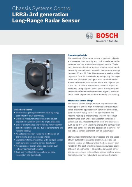
Mechanical <strong>sensor</strong> design<br />
The robust <strong>sensor</strong> design without any mechanically<br />
moving parts and its high mechanical vibration resistance<br />
allows the application in commercial vehicles,<br />
particularly in heavy trucks. An optional lens and<br />
radome heating is implemented to allow full <strong>sensor</strong><br />
performance even under bad weather conditions<br />
(snow and ice). Important parameters and interfaces<br />
such as field of view (opening angle), the configuration<br />
of the car connector and the position of the mirror for<br />
the optical <strong>sensor</strong> alignment can be customized.<br />
Standardized manufacturing processes and the usage<br />
of fully automotive qualified electronic devices (according<br />
to AEC Q100) guarantee the best quality and<br />
reliability. The cost-effective design encourages application<br />
in all segments. It also makes advanced driver<br />
assistance systems with multiple <strong>sensor</strong> configurations<br />
(complementary or redundant) economically viable.
Chassis Systems Control | <strong>Long</strong>-Range Radar Sensor LRR3<br />
Technical features<br />
Frequency <strong>range</strong><br />
76…77 GHz<br />
Distance<br />
0.5…250 m<br />
Accuracy<br />
±0.1 m<br />
Relative speed<br />
-75 …+60 m/s<br />
Accuracy<br />
±0.12 m/s<br />
Vision <strong>range</strong><br />
Horizontal opening angle 30 ° (-6 dB)<br />
Vertical opening angle 5 ° (-6 dB)<br />
Modulation<br />
FMCW<br />
Max. number of detected objects 32<br />
Operating temperature<br />
-40 °C…+85 °C (periphery)<br />
Vehicle connector<br />
MQS 8 Pins<br />
Cycle time (incl. auto diagnosis) typically 80 ms<br />
Dimensions (H x W x D)<br />
77 mm x 74 mm x 58 mm<br />
Weight<br />
285 g<br />
Power consumption<br />
typically 4 W<br />
ISO certification<br />
ISO 15622 Class IV <strong>sensor</strong><br />
Sensor architecture<br />
The LRR3 <strong>sensor</strong> is a monostatic Frequency Modulated<br />
Continuous Wave (FMCW) <strong>radar</strong> with four fixed beams.<br />
An important aspect of the <strong>sensor</strong> architecture is the<br />
high level of integration for the RF-functionality as well<br />
as for the <strong>sensor</strong> control unit and the signal processing.<br />
This results in a highly reliable and compact <strong>sensor</strong>.<br />
We use cost-effective, fully silicon based technology<br />
for the RF-components. Innovative signal processing<br />
algorithms allow excellent measurement performance<br />
and the handling of complex traffic situations such<br />
as a “lane free detection” by angular separation of<br />
ob jects. Our dedicated safety concept guarantees<br />
the compatibility of the <strong>sensor</strong> with safety relevant<br />
applications.<br />
The <strong>sensor</strong> consists of two PCBs:<br />
The RF-module contains the RF-circuitry (SiGe-<br />
MMICs) and the Radar-ASIC with integrated modulation<br />
control and the signal pre-processing (preamplification,<br />
A/D conversion, filtering).<br />
The <strong>sensor</strong> control unit contains the microcontroller,<br />
the System-ASIC and optionally a FlexRay transceiver.<br />
The integrated sequencer takes over control tasks<br />
of the <strong>radar</strong> <strong>sensor</strong>. This enables the handling of new<br />
signal processing algorithms by the microcontroller<br />
as certain time consuming task schemes are outsourced<br />
and taken over by the Radar-ASIC. The micro-<br />
controller has been developed especially for driver<br />
assistance systems. The System-ASIC forms an<br />
essential part of the safety concept. It provides the<br />
power supply and contains the CAN interfaces.<br />
Sensor performance<br />
The LRR3 <strong>sensor</strong> exhibits a combined patch lens antenna<br />
which is well suited for large frequency ramps allow-<br />
ing a high resolution in distance. Its advanced antenna<br />
design enables a detection <strong>range</strong> of 0.5 up to 250 m<br />
with a field of view of 30°. The field of view can be customized<br />
to an opening angle up to 45° by modifying<br />
the aperture of the lens. LRR3 provides excellent measurement<br />
accuracy of angle, velocity and distance as<br />
well as object separation.<br />
Applications<br />
The LRR3 is the centerpiece of the automatic distance<br />
and speed control system ACC (Adaptive Cruise Control)<br />
and Predictive Emergency Braking Systems. ACC<br />
and the Predictive Emergency Braking Systems network<br />
the <strong>radar</strong> <strong>sensor</strong> with the ESP® system.<br />
ACC uses information from the long-<strong>range</strong> <strong>radar</strong> <strong>sensor</strong><br />
to control the vehicle’s speed by automatically braking<br />
and accelerating so that it maintains at a predefined<br />
minimum distance from the preceding vehicle.<br />
Our Predictive Emergency Braking Systems continuously<br />
monitor the situation in front of the vehicle and<br />
trigger appropriate collision avoidance/mitigation<br />
measures in critical situations. They support the driver<br />
with an intelligent predictive warning concept and also<br />
provide effective emergency braking assistance in<br />
critical situations. If a collision is unavoidable, the<br />
system automatically triggers emergency braking in<br />
order to reduce the risk of injury.<br />
Via intelligent networking of our <strong>radar</strong> <strong>sensor</strong> with<br />
components and systems installed in the vehicle or by<br />
integrating information of other <strong>sensor</strong>s such as a<br />
camera or additional <strong>radar</strong> <strong>sensor</strong>s we enable new<br />
applications or enhancements of existing functions.<br />
Through the use of multiple <strong>sensor</strong>s and components<br />
we further increase the safety of vehicle occupants<br />
and other road users without increasing cost. <strong>Bosch</strong><br />
collects this networking of components and systems<br />
under the name CAPS – Combined Active Passive<br />
Safety.<br />
Robert <strong>Bosch</strong> GmbH<br />
Chassis Systems Control<br />
Driver Assistance<br />
Postfach 16 61<br />
71226 Leonberg<br />
Germany<br />
www.bosch.de/k<br />
www.bosch-acc.com<br />
Printed in Germany<br />
292000P03W-C/SMC2-200906-En<br />
© Robert <strong>Bosch</strong> GmbH 2009. All rights reserved, also regarding any disposal, exploitation, reproduction,<br />
editing, distribution, as well as in the event of applications for industrial property rights.