DIRECT VENT GAS WATER HEATER - Bradford White
DIRECT VENT GAS WATER HEATER - Bradford White
DIRECT VENT GAS WATER HEATER - Bradford White

Create successful ePaper yourself
Turn your PDF publications into a flip-book with our unique Google optimized e-Paper software.
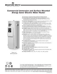
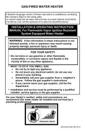
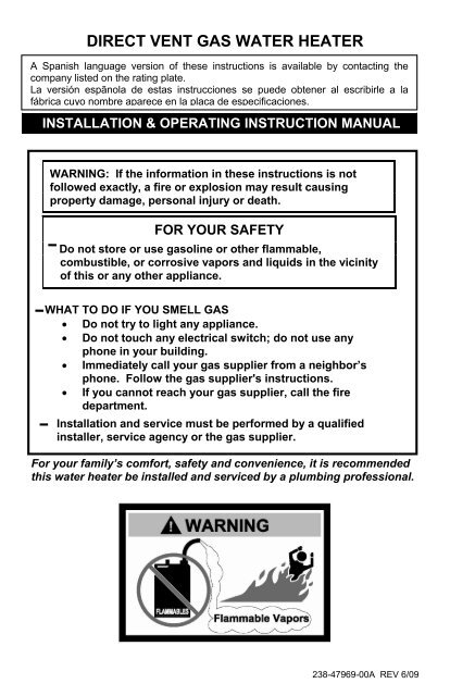
<strong>DIRECT</strong> <strong>VENT</strong> <strong>GAS</strong> <strong>WATER</strong> <strong>HEATER</strong><br />
A Spanish language version of these instructions is available by contacting the<br />
company listed on the rating plate.<br />
La versión espãnola de estas instrucciones se puede obtener al escribirle a la<br />
fábrica cuyo nombre aparece en la placa de especificaciones.<br />
INSTALLATION & OPERATING INSTRUCTION MANUAL<br />
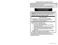
WARNING: If the information in these instructions is not<br />
followed exactly, a fire or explosion may result causing<br />
property damage, personal injury or death.<br />
FOR YOUR SAFETY<br />
Do not store or use gasoline or other flammable,<br />
combustible, or corrosive vapors and liquids in the vicinity<br />
of this or any other appliance.<br />
WHAT TO DO IF YOU SMELL <strong>GAS</strong><br />
• Do not try to light any appliance.<br />
• Do not touch any electrical switch; do not use any<br />
phone in your building.<br />
• Immediately call your gas supplier from a neighbor’s<br />
phone. Follow the gas supplier's instructions.<br />
• If you cannot reach your gas supplier, call the fire<br />
department.<br />
Installation and service must be performed by a qualified<br />
installer, service agency or the gas supplier.<br />
For your family’s comfort, safety and convenience, it is recommended<br />
this water heater be installed and serviced by a plumbing professional.<br />
238-47969-00A REV 6/09
CONGRATULATIONS!<br />
You have just purchased one of the finest water heaters on the<br />
market today!<br />
This installation, operation and instruction manual will explain in<br />
detail the installation and maintenance of your new Direct Vent Gas<br />
Water Heater. We strongly recommend that you contact a plumbing<br />
professional for the installation of this water heater.<br />
We require that you carefully read this manual, as well as the<br />
enclosed warranty, and refer to it when questions arise. If you<br />
have any specific questions concerning your warranty, please<br />
consult the plumbing professional from whom your water heater<br />
was purchased. For your records we recommend that you write the<br />
model, serial number and installation date of your water heater in<br />
the maintenance section in the back of this manual.<br />
This manual should be kept with the water heater.<br />
We’re committed to providing you with the finest water heater made.<br />
2
TABLE OF CONTENTS<br />
page<br />
GENERAL INFORMATION ......................................................................... 4<br />
INSTALLATION........................................................................................ 5<br />
Locating The Water Heater .................................................................... 5<br />
Minimum Clearances .............................................................................. 8<br />
Optional Direct Vent-Air Intake Terminal Guard.................................. 9<br />
Venting ..................................................................................................... 11<br />
Water Connections ................................................................................. 14<br />
Gas Connections .................................................................................... 17<br />
GENERAL OPERATION ............................................................................. 18<br />
Lighting and Shutdown Instructions .................................................... 19<br />
Thermostat Adjustment.......................................................................... 21<br />
Burner Flame Checks ............................................................................. 23<br />
MAINTENANCE........................................................................................... 24<br />
DIAGNOSTICS FOR HONEYWELL CONTROL......................................... 27<br />
PARTS LIST AND DRAWING..................................................................... 29<br />
INSTALLATIONS FOR POTABLE <strong>WATER</strong> AND SPACE HEATING ....... 30<br />
NOTES..........................................................................................................31<br />
3
GENERAL INFORMATION<br />
This gas-fired water heater’s design is certified by CSA International under<br />
the American National Standard Z21.10.1 - (latest edition) and CSA 4.1-M -<br />
(latest edition).<br />
This water heater must be installed in accordance with local codes or, in the<br />
absence of local codes, the National Fuel Gas Code, ANSI Z223.1- (Latest<br />
Edition) and/or in Canada CAN/CGA B149 Installation Codes (Latest<br />
Editions). The warranty for this water heater is in effect only when the water<br />
heater is installed, adjusted, and operated in accordance with these<br />
Installation and Operating Instructions. The manufacturer will not be held<br />
liable for any damage resulting from alteration and/or failure to comply with<br />
these instructions.<br />
This water heater is not design certified for installation in a mobile home.<br />
Such an installation may create a hazardous condition and will nullify the<br />
warranty.<br />
This water heater has been designed and certified for the purpose of heating<br />
potable water. The installation and use of this water heater for any purpose<br />
other than the heating of potable water may cause damage to the water<br />
heater and create a hazardous condition and nullify the warranty.<br />
WARNING<br />
Incorrect operation of this appliance may create a hazard to life and<br />
property and will nullify the warranty.<br />
Do not use this appliance if any external part has been submerged in water.<br />
You should contact a qualified service technician to inspect the appliance<br />
and to replace any part of the control system including the combination gas<br />
control, which has been submerged in water.<br />
DANGER<br />
Do not store or use gasoline or other flammable, combustible, or<br />
corrosive vapors and liquids in the vicinity of this or any other<br />
appliance.<br />
4
General Information continued-<br />
IMPORTANT<br />
Before proceeding, please inspect the water heater and its components<br />
for possible damage. DO NOT install any damaged components. If<br />
damage is evident then please contact the supplier where the water<br />
heater was purchased or the manufacturer listed on the rating plate for<br />
replacement parts.<br />
Make sure that you check the rating plate and combination gas control on<br />
the water heater to be certain that the type of gas being supplied<br />
corresponds with the marking on the rating plate and combination gas<br />
control.<br />
A sacrificial anode is used to extend tank life. The removal of this anode, for<br />
any reason, will nullify the warranty. In areas where water is unusually active,<br />
an odor may occur at the hot water faucet due to a reaction between the<br />
sacrificial anode and the impurities in the water. If this should happen, an<br />
alternative anode may be purchased from the supplier that installed this<br />
water heater. This will minimize the odor while protecting the tank.<br />
Additionally, the water heater should be flushed with appropriate dissolvers<br />
to eliminate any bacteria.<br />
INSTALLATION<br />
WARNING<br />
Water heaters are heat producing appliances. To avoid damage or injury,<br />
do not store materials against the water heater or vent-air intake system.<br />
Use proper care to avoid unnecessary contact (especially by children)<br />
with the water heater and vent-air intake components. UNDER NO<br />
CIRCUMSTANCES SHALL FLAMMABLE MATERIALS, SUCH AS<br />
<strong>GAS</strong>OLINE OR PAINT THINNER BE USED OR STORED IN THE<br />
VICINITY OF THIS <strong>WATER</strong> <strong>HEATER</strong>, <strong>VENT</strong>-AIR INTAKE SYSTEM OR<br />
IN ANY LOCATION FROM WHICH FUMES COULD REACH THE<br />
<strong>WATER</strong> <strong>HEATER</strong> OR <strong>VENT</strong>-AIR INTAKE SYSTEM.<br />
LOCATING THE <strong>WATER</strong> <strong>HEATER</strong><br />
This water heater MUST NOT be installed in any location where gasoline or<br />
flammable vapors are likely to be present, unless the installation is such to<br />
eliminate the probable ignition of gasoline or flammable vapors.<br />
Water heaters in residential garages must be installed and located, or<br />
protected, to avoid physical damage. For other installations refer to<br />
local codes. In the absence of local codes, the water heater must be<br />
installed in compliance with the National Fuel Gas Code, (ANSI Z223.1-<br />
Latest Edition), or in Canada CAN/CGA B149.1 Natural Gas Installation<br />
Code (Latest Edition) or CAN/CGA B149.2 Propane Installation Code<br />
(Latest Edition).<br />
5
Installation (Locating The Water Heater) continued-<br />
The location of this water heater is of the utmost importance. Before<br />
installing this water heater read the Installation section of these instructions.<br />
After reading these Installation and Operating Instructions, select a location<br />
for the water heater where the floor is level and is easily accessible to gas<br />
and water supply lines. DO NOT locate the water heater where water<br />
lines could be subjected to freezing temperatures. Make sure the cold<br />
water pipes are not located directly above the gas control so that<br />
condensate during humid weather does not drip on the controls.<br />
This water heater MUST be installed indoors out of the wind and<br />
weather.<br />
To comply with NSF requirements this water heater is to be:<br />
a) Sealed to the floor with sealant, in a smooth and easily cleanable<br />
way, or<br />
b) Installed with an optional leg kit that includes legs and/or extensions<br />
that provide a minimum clearance of 6” beneath the water heater.<br />
Note: For California installation this water heater must be braced,<br />
anchored, or strapped to avoid falling or moving during an earthquake.<br />
See instructions for correct installation procedures. Instructions may<br />
be obtained from DSA Headquarters Office, 1102 Q Street, Suite 5100,<br />
Sacramento, CA 95811.<br />
Water heater corrosion and component failure can be caused by the heating<br />
and breakdown of airborne chemical vapors. Examples of some typical<br />
compounds that are potentially corrosive are: spray can propellants, cleaning<br />
solvents, refrigerator and air conditioning refrigerants, swimming pool<br />
chemicals, calcium and sodium chloride, waxes and process chemicals.<br />
These materials are corrosive at very low concentration levels with little or no<br />
odor to reveal their presence. NOTE: DAMAGE TO THE <strong>WATER</strong> <strong>HEATER</strong><br />
CAUSED BY EXPOSURE TO CORROSIVE VAPORS IS NOT COVERED<br />
BY THE WARRANTY. DO NOT OPERATE THE <strong>WATER</strong> <strong>HEATER</strong> IF<br />
EXPOSURE HAS OR WILL OCCUR. DO NOT STORE ANY<br />
POTENTIALLY CORROSIVE COMPOUNDS IN THE VICINITY OF THE<br />
<strong>WATER</strong> <strong>HEATER</strong>.<br />
6
Installation (Locating The Water Heater) continued-<br />
WARNING<br />
Liquefied petroleum gases/propane gas are heavier than air and will<br />
remain at floor level if there is a leak. Basements, crawl spaces, closets<br />
and areas below ground level will serve as pockets for accumulation of<br />
leaking gas. Before lighting, smell all around the appliance area for gas.<br />
Be sure to smell next to the floor.<br />
IF YOU SMELL <strong>GAS</strong>:<br />
• Do not try to light any appliance.<br />
• Do not touch any electric switch; do not use any telephone in your<br />
building.<br />
• Immediately call your gas supplier from a neighbor’s<br />
telephone. Follow the gas supplier’s instructions.<br />
• If you cannot reach your gas supplier, call the fire department.<br />
DO NOT OPERATE APPLIANCE UNTIL THE LEAKAGE IS<br />
CORRECTED!<br />
DO NOT ATTEMPT TO LIGHT ANY <strong>GAS</strong> APPLIANCE IF YOU ARE<br />
NOT CERTAIN OF THE FOLLOWING:<br />
• Liquefied petroleum gases/propane gas and natural gas have an<br />
odorant added by the gas supplier that aids in the detection of the<br />
gas.<br />
• Most people recognize this odor as a “sulfur” or “rotten egg”<br />
smell.<br />
• Other conditions, such as “odorant fade” can cause the odorant to<br />
diminish in intensity, or ”fade”, and not be as readily detectable.<br />
• If you have a diminished sense of smell, or are in any way unsure of<br />
the presence of gas, immediately contact your gas supplier<br />
from a neighbor’s telephone.<br />
• Gas detectors are available. Contact your gas supplier, or plumbing<br />
professional, for more information.<br />
7
Installation (Locating The Water Heater) continued-<br />
The water heater must be located close enough to the outside wall to keep<br />
the venting distance within the maximum distance described in the vent kit’s<br />
installation instructions. Note: The direct vent-air intake terminal must be<br />
installed on a vertical wall. Read the instructions from the vent kit that was<br />
purchased with the water heater before locating the water heater.<br />
This water heater must be located in an area where leakage of the tank or<br />
water line connections and the combination temperature and pressure relief<br />
valve will not result in damage to the area adjacent to the water heater or to<br />
lower floors of the structure. When such locations cannot be avoided, a<br />
suitable drain pan, adequately drained, must be installed under the water<br />
heater. The pan must not restrict combustion airflow. The drain pan must<br />
have a minimum length and width of at least 4 in. (10.2 cm) greater than the<br />
diameter of the water heater and must not restrict proper combustion air flow<br />
to the water heater. The drain pan, as described above, can be purchased<br />
from your plumbing professional. The drain pan must be piped to an<br />
adequate drain. The piping must be at least 3/4 inch (1.9 cm) in diameter<br />
and pitched for proper drainage.<br />
It is recommended that a minimum clearance of four (4) inches (10.2 cm) be<br />
provided on the side of the water heater for servicing and maintenance of the<br />
combination temperature and pressure relief valve.<br />
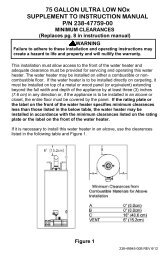
MINIMUM CLEARANCES<br />
WARNING<br />
Failure to adhere to these installation and operating instructions may<br />
create a hazard to life and property and will nullify the warranty.<br />
This installation must allow access to the front of the water heater and<br />
adequate clearance must be provided for servicing and operating this<br />
water heater. The water heater may be installed on either a combustible or<br />
non-combustible floor. If the water heater is to be installed directly on<br />
carpeting, it must be installed on top of a metal or wood panel extending<br />
beyond the full width and depth of the appliance by at least three (3) inches<br />
(76.2 mm) in any direction or, if the appliance is to be installed in an alcove<br />
or closet, the entire floor must be covered by the panel. The minimum<br />
clearances to combustibles for this water heater is: zero (0) inch (0 cm) from<br />
the sides and rear, four (4) inches (10.2 cm) from the front of the jacket, zero<br />
(0) inch (0 cm) from the plenum, zero (0) inch (0 cm) from the air intake<br />
tubes and twelve (12) inches (30.5 cm) from the direct vent-air intake<br />
terminal. (See Figure 1).<br />
8
OPTIONAL <strong>DIRECT</strong> <strong>VENT</strong>-AIR INTAKE TERMINAL GUARD<br />
WARNING<br />
The direct vent-air intake terminal is HOT while the water heater is in<br />
operation. Do not touch. Keep children, combustibles, gasoline and<br />
other liquids having flammable vapors away.<br />
It is recommended that a vent-air intake terminal guard be installed when the<br />
vent-air intake terminal is located where it can be touched accidentally, or<br />
accessed by children. (See Figure 2).<br />
A chain link or louvered fence may be used instead of the vent-air intake<br />
terminal guard. Maintain proper clearances as specified in this instruction<br />
manual to the vent-air intake terminal. (See Figure 3).<br />
Figure 1<br />
9
Installation continued-<br />
Figure 2<br />
Figure 3<br />
10
<strong>VENT</strong>ING<br />
WARNING<br />
The vent-air intake system must be properly installed. Failure to properly<br />
install the vent-air intake system could result in property damage,<br />
personal injury or death.<br />
DO NOT install any damaged vent-air intake system components.<br />
Contact the manufacturer of the water heater for replacement parts.<br />
This is a Direct Vent Gas Water Heater where all air for combustion is<br />
obtained from the outside atmosphere and all flue gases are discharged to<br />
the outside atmosphere. A vent kit that was designed for use with this<br />
water heater must be used when installing this water heater. If a vent<br />
kit was provided with the water heater, install the water heater with that<br />
vent kit per the instructions provided in the vent kit. If a vent kit was<br />
not provided with the water heater, refer to the label on the water<br />
heater to determine the proper vent kit options. Contact the supplier<br />
that you purchased the water heater from to obtain the correct vent kit.<br />
11
Figure 4<br />
Direct Vent Terminal Clearances<br />
Canadian Installations1 US Installations2<br />
A=<br />
Clearance above grade, veranda, porch, deck or<br />
balcony<br />
12 inches (30 m) 12 inches (30 cm)<br />
B= Clearance to widow or door that may be opened 12 inches (30 m)<br />
9 inches (23 cm) for<br />
appliances > 10,000 Btuh<br />
(3 kW) and ≤ 50,000<br />
Btuh (15 kW), 12 inches<br />
(30 cm) for appliances ><br />
50,000 Btuh (15 kW)<br />
C= Clearance to permanently closed widow *b *b<br />
D=<br />
Vertical clearance to ventilated soffit located above the<br />
terminal within a horizontal distance of 2 feet (61 cm) 12 inches (30 cm) *a 12 inches (30 cm) *a<br />
from the center line of the terminal<br />
E= Clearance to unventilated soffit 12 inches (30 cm) *a 12 inches (30 cm) *a<br />
F= Clearance to outside corner *b *b<br />
G= Clearance to inside corner *b *b<br />
H=<br />
I=<br />
J=<br />
Clearance to each side of center line extended above<br />
meter/regulator assembly<br />
Clearance to service regulator vent outlet or oil tank<br />
vent<br />
Clearance to non-mechanical air supply inlet to building<br />
or the combustion air inlet to any other appliance<br />
3 feet (91 cm) within a<br />
height 15 feet (4.6 m)<br />
above the<br />
meter/regulator<br />
assembly<br />
*b<br />
36 inches (91 cm) *b<br />
12 inches (30 cm)<br />
K= Clearance to a mechanical air supply inlet 6 feet (1.83 m)<br />
9 inches (23 cm) for<br />
appliances > 10,000 Btuh<br />
(3 kW) and ≤ 50,000<br />
Btuh (15 kW), 12 inches<br />
(30 cm) for appliances ><br />
50,000 Btuh (15 kW)<br />
3 feet (91 cm) above if<br />
within 10 feet horizontally<br />
L=<br />
Clearance above paved sidewalk or paved driveway<br />
located on public property<br />
7 feet (2.13 m)† *b<br />
M= Clearance under a veranda, porch, deck, or balcony 12 inches (30 cm) ‡ *b<br />
12
Venting continued-<br />
1<br />
In accordance with the current CAN/CGA-B149 Installation Codes.<br />
2<br />
In accordance with the current ANSI Z223.1-(Latest edition)/NFPA 54 National Fuel Gas Code.<br />
† A vent must not terminate directly above a sidewalk or paved driveway that is located between two singlefamily<br />
dwellings and serves both dwellings.<br />
‡ Permitted only if a veranda, porch, deck or balcony is fully open on a minimum of two sides beneath the<br />
floor.<br />
*a) A minimum clearance value determined by testing in accordance with section 2.20.<br />
*b) “Clearance in accordance with local installation codes and the requirements of the gas supplier”.<br />
The vent system must terminate so that proper clearances are maintained as cited in<br />
local codes or the latest edition of the National Fuel Gas Code, ANSI Z223.1 – (latest<br />
edition) as follows:<br />
1. Do not terminate near soffit vents or crawl space or other area where condensate<br />
or vapor could create a nuisance or hazard or cause property damage.<br />
2. Do not terminate the exhaust vent terminal where condensate or vapor could<br />
cause damage or could be detrimental to the operation of regulators, relief<br />
valves, or other equipment.<br />
3. Do not terminate the exhaust vent terminal over public area or walkways where<br />
condensate or vapor can cause nuisance or hazard.<br />
4. The vent must terminate a minimum of 12 inches above expected snowfall level<br />
to prevent blockage of vent termination.<br />
Vent pipes serving direct vent appliances are classified by building codes as “vent<br />
connectors”. Required clearances from combustible materials must be provided in<br />
accordance with information in this manual under LOCATION OF <strong>WATER</strong> <strong>HEATER</strong><br />
and CLEARANCES, and with National Fuel Gas Code and local code.<br />
13
<strong>WATER</strong> CONNECTIONS<br />
Note: BEFORE PROCEEDING WITH THE INSTALLATION, CLOSE THE<br />
MAIN <strong>WATER</strong> SUPPLY VALVE.<br />
After shutting off the main water supply, open a faucet to relieve the water<br />
line pressure to prevent any water from leaking out of the pipes while making<br />
the water connections to the water heater. After the pressure has been<br />
relieved, close the faucet. The COLD water inlet and HOT water outlet are<br />
identified on the top of the water heater. The fittings at the cold water inlet<br />
and hot water outlet are dielectric waterway fittings with 3/4” NPT male<br />
thread. Make the proper plumbing connections between the water heater<br />
and the plumbing system to the house. Install a shut-off valve in the cold<br />
water supply line.<br />
CAUTION<br />
If sweat fittings are to be used, DO NOT apply heat to the nipples on top of<br />
the water heater. Sweat the tubing to the adapter before fitting the adapter<br />
to the water connections. It is imperative that heat is not applied to the<br />
nipples containing a plastic liner.<br />
APPROXIMATE TIME/TEMPERATURE RELATIONSHIPS IN SCALDS<br />
120°F (49°C) More than 5 minutes<br />
125°F (52°C) 1½ to 2 minutes<br />
130°F (54°C) About 30 seconds<br />
135°F (57°C) About 10 seconds<br />
140°F (60°C) Less than 5 seconds<br />
145°F (63°C) Less than 3 seconds<br />
150°F (66°C) About 1½ seconds<br />
155°F (68°C) About 1 second<br />
14
Water Connections continued-<br />
WARNING<br />
For protection against excessive temperatures and pressure, install<br />
temperature and pressure protective equipment required by local codes,<br />
but not less than a combination temperature and pressure relief valve<br />
certified by a nationally recognized testing laboratory that maintains<br />
periodic inspection of production of listed equipment or materials as<br />
meeting the requirements of the Standard for Relief Valves and<br />
Automatic Gas Shutoff Devices for Hot Water Supply Systems, ANSI<br />
Z21.22 and the Standard CAN1-4.4 Temperature, Pressure,<br />
Temperature and Pressure Relief Valves and Vacuum Relief Valves.<br />
The combination temperature and pressure relief valve must be marked<br />
with a maximum set pressure not to exceed the maximum working<br />
pressure of the water heater. The hourly BTU discharge capacity or the<br />
rated steam relief capacity of the combination temperature and pressure<br />
relief valve must not be less than the input rating of the water heater.<br />
Install the combination temperature and pressure relief valve into the<br />
opening provided and marked for this purpose on the water heater.<br />
Note: Some models may already be equipped or supplied with a<br />
combination temperature and pressure relief valve. Verify that the<br />
combination temperature and pressure relief valve complies with local<br />
codes. If the combination temperature and pressure relief valve does<br />
not comply with local codes, replace it with one that does. Follow the<br />
installation instructions above on this page.<br />
Install a discharge line that terminates six (6) inches (15 cm) above the<br />
floor, or any distance below the structural floor, to the outlet of the<br />
combination temperature and pressure relief valve. DO NOT allow<br />
water from the discharge line to contact any live electrical part. The<br />
discharge line is to be installed to allow for complete drainage of both<br />
the combination temperature and pressure relief valve and the discharge<br />
line. The water from the discharge line must be directed to a suitable<br />
drain or area that will not be damaged by water Refer to “LOCATING<br />
THE <strong>WATER</strong> <strong>HEATER</strong>.” The discharge opening must not be subjected<br />
to blockage or freezing. DO NOT thread, plug or cap the discharge line.<br />
It is recommended that a minimum clearance of four (4) inches (10.2<br />
cm) be provided on the side of the water heater for servicing and<br />
maintenance of the combination temperature and pressure relief valve.<br />
Do not place a shutoff valve between the combination temperature and<br />
pressure relief valve and the water heater, or on discharge pipes<br />
between such valves or the atmosphere.<br />
15
Water Connections continued-<br />
WARNING<br />
FAILURE TO INSTALL AND MAINTAIN A NEW, LISTED 3/4” X 3/4”<br />
TEMPERATURE AND PRESSURE RELIEF VALVE WILL RELEASE<br />
THE MANUFACTURER FROM ANY CLAIM, WHICH MIGHT RESULT<br />
FROM EXCESSIVE TEMPERATURES AND PRESSURES.<br />
If this water heater is installed in a closed water supply system, such as the<br />
one having a back-flow preventer in the cold water supply, provisions must<br />
be made to control thermal expansion. DO NOT operate this water heater in<br />
a closed system without provisions for controlling thermal expansion. Your<br />
water supplier or local plumbing inspector should be contacted on how to<br />
control this situation.<br />
After installation of the water lines, open the main water supply valve and fill<br />
the water heater. While the water heater is filling, open several hot water<br />
faucets to allow air to escape from the water system. When a steady stream<br />
of water flows through the faucets, close them and check all water<br />
connections for possible leaks. NEVER OPERATE THE <strong>WATER</strong> <strong>HEATER</strong><br />
WITHOUT FIRST BEING CERTAIN IT IS FILLED WITH <strong>WATER</strong>.<br />
WARNING<br />
Hydrogen gas can be produced in an operating water heater that has<br />
not had water drawn from the tank for a long period of time (generally<br />
two (2) weeks or more). Hydrogen gas is extremely flammable. To<br />
prevent the possibility of injury under these conditions, we recommend<br />
the hot water faucet to be open for several minutes at the kitchen sink<br />
before you use any electrical appliance that is connected to the hot<br />
water system. If hydrogen is present, there will be an unusual sound<br />
such as air escaping through the pipes as hot water begins to flow. Do<br />
not smoke or have open flame near the faucet at the time it is open.<br />
This water heater can deliver scalding temperature water at any faucet in the<br />
system. Be careful whenever using hot water to avoid scalding injury.<br />
Certain appliances such as dishwashers and automatic clothing washers<br />
may require increased temperature water. By setting the thermostat on this<br />
water heater to obtain the increased temperature water required by these<br />
appliances, you may create the potential for scald injury. To protect against<br />
injury, you should install an ASSE approved mixing valve in the water<br />
system. This valve will reduce point of discharge temperature by mixing cold<br />
and hot water in branch supply lines. Such valves are available from the<br />
manufacturer of this water heater or a local plumbing supplier. Please<br />
consult with a plumbing professional.<br />
16
Gas Connections<br />
The gas supply lines must meet all requirements of the National Fuel Gas Code<br />
(ANSI Z223.1-Latest Edition), or in Canada CAN/CGA B149.1 Natural Gas<br />
Installation Code (Latest Edition) or CAN/CGA B149.2 Propane Installation Code<br />
(Latest Edition).<br />
The minimum permissible gas supply pressure for the purpose of input adjustment is<br />
one (1.0) inch (0.25 kPa) water column above the operating manifold pressure. See<br />
the rating plate and gas valve for the manifold pressure and gas type. The maximum<br />
permissible gas supply pressure is fourteen (14.0) inches (3.5 kPa) water column for<br />
natural gas and liquefied petroleum gases/propane gas.<br />
1. Connect this water heater only to the type of gas (Natural or Propane gas) as<br />
shown on the rating plate. Use clean black iron pipe or equivalent material<br />
approved by local codes and ordinances. (Dirt and scale from the pipe can enter<br />
the gas valve and cause it to malfunction). The inlet gas line must have a<br />
minimum length of three (3) inches (7.6 cm) drip leg (sediment trap) installed as<br />
close to the water heater’s gas valve as possible. A ground joint union must be<br />
installed as close to the water heater as possible in the gas supply line feeding<br />
the water heater to permit servicing of the water heater. Compounds used on the<br />
threaded joints of the gas piping must be resistant to the action of liquefied<br />
petroleum gases/propane gas. DO NOT apply pipe dope to the gas valve inlet<br />
and make certain that no pipe dope has become lodged in the inlet screen of the<br />
gas valve. Extreme care must be taken to ensure no pipe dope enters the gas<br />
valve. Avoid excessive torque when tightening the gas supply line to the gas<br />
valve. Excessive torque may result in cracking of the gas valve housing and<br />
could create a gas leak. When tightening gas supply line to L.P. control, it is<br />
recommended to hold the inlet body of the control securely with an adequate<br />
wrench. The suggested maximum torque is 31.5 ft. lbs. (4.4 kg-m).<br />
WARNING<br />
The manufacturer of this water heater will not be liable for any damage or injury<br />
caused as a result of a cracked gas inlet as a result of excessive torque.<br />
2. This water heater and its gas connection must be leak tested before placing the<br />
water heater in operation. Check for gas leaks with a soap and water solution<br />
and a brush or a commercial leak detector fluid. NEVER USE A MATCH OR<br />
OPEN FLAME FOR TESTING!<br />
CAUTION<br />
The water heater and individual shutoff valve must be disconnected from the gas<br />
supply piping system during any pressure testing of the system at test pressures<br />
in excess of 1/2 psi (3.5 kPa). The water heater must be isolated from the gas<br />
supply piping system by closing its manual shutoff valve during any pressure<br />
testing of the gas supply system at test pressures equal to or less than 1/2 psi<br />
(3.5 kPa). The supply line must be capped when not connected to the water<br />
heater.<br />
3. While checking for leaks care must be taken to prevent solution from<br />
contacting the electrical connections at the control. If electrical connections at the<br />
control become wet, they must be thoroughly dried before attempting to operate<br />
the water heater.<br />
17
GENERAL OPERATION<br />
WARNING<br />
Water heaters are heat producing appliances. To avoid damage or<br />
injury, do not store materials against the water heater or vent-air intake<br />
system. Use proper care to avoid unnecessary contact (especially by<br />
children) with the water heater and vent-air intake system. UNDER NO<br />
CIRCUMSTANCES MUST FLAMMABLE MATERIALS, SUCH AS<br />
<strong>GAS</strong>OLINE OR PAINT THINNER BE USED OR STORED IN THE<br />
VICINITY OF THIS <strong>WATER</strong> <strong>HEATER</strong>, <strong>VENT</strong>-AIR INTAKE SYSTEM<br />
OR IN ANY LOCATION FROM WHICH FUMES COULD REACH THE<br />
<strong>WATER</strong> <strong>HEATER</strong> OR <strong>VENT</strong>-AIR INTAKE SYSTEM.<br />
TO FILL THE <strong>WATER</strong> <strong>HEATER</strong><br />
1. Close the water heater drain valve by turning the knob clockwise .<br />
2. Open the cold water supply shut-off valve.<br />
3. Open several hot water faucets to allow air to escape from the system.<br />
4. When a steady stream of water flows from the faucets, the water heater<br />
is filled. Close the faucets and check for water leaks at the water<br />
heater drain valve, combination temperature and pressure relief valve<br />
and the hot and cold water connections.<br />
TO DRAIN THE <strong>WATER</strong> <strong>HEATER</strong><br />
Should it become necessary to completely drain the water heater, make sure<br />
you follow the steps below:<br />
1. Set the thermostat dial to the lowest possible position.<br />
2. Rotate and if applicable partially depress gas control knob clockwise<br />
to the “OFF” position.<br />
3. Shut off the gas supply to the water heater.<br />
4. Close the cold water supply shut-off valve.<br />
5. Open the drain valve on the water heater by turning the knob counterclockwise<br />
. The drain valve has threads on the end that will allow<br />
the connection of a standard hose coupling.<br />
6. Open a hot water faucet to allow air to enter the system.<br />
To refill the water heater, refer to “To Fill the Water Heater.”<br />
18
Lighting & Shutdown Instructions – <strong>White</strong> Rodgers and Robertshaw gas<br />
control.<br />
19
Lighting & Shutdown Instructions Continued - Honeywell gas control.<br />
20
THERMOSTAT ADJUSTMENT - <strong>White</strong> Rodgers gas control.<br />
160°F Control 180°F Control<br />
Figure 5<br />
The thermostat dial is set to its lowest temperature setting when shipped from the factory.<br />
Remember that lower temperature settings are more energy efficient. Adjust the<br />
temperature by turning the thermostat dial. It is suggested that the starting point setting not be<br />
greater than the ” “ or “ “mark on the thermostat dial (approximately 120°F [48.9°C]) as<br />
indicated above. Rotate the thermostat dial clockwise to decrease the temperature<br />
setting. Rotate the thermostat dial counter-clockwise to increase the temperature<br />
setting. Adjust the dial until the minimum acceptable temperature is achieved (See figure 5<br />
above for approximate temperature settings).<br />
Robertshaw gas control.<br />
160°F Control 180°F Control<br />
Figure 6<br />
The thermostat dial is set to its lowest temperature setting when shipped from the factory.<br />
Remember that lower temperature settings are more energy efficient. Adjust the<br />
temperature by turning the thermostat dial. It is suggested that the starting point setting not be<br />
greater than the “ ” mark on the thermostat dial (approximately 120°F [48.9°C]) as indicated<br />
above. Rotate the thermostat dial counter-clockwise to decrease the temperature<br />
setting. Rotate the thermostat dial clockwise to increase the temperature setting.<br />
Adjust the dial until the minimum acceptable temperature is achieved (See figure 6 above for<br />
approximate temperature settings).<br />
21
Thermostat Adjusting continued – Honeywell control.<br />
22
Thermostat Adjusting continued-<br />
DANGER<br />
Hotter water increases the risk of scald injury. Scalding may occur within five (5)<br />
seconds at a temperature setting of 140° F (60° C). To protect against hot water<br />
injury, install an ASSE approved mixing valve in the water system. This valve<br />
will reduce point of discharge temperature by mixing cold and hot water in branch<br />
water lines. A licensed plumbing professional or local plumbing authority should<br />
be consulted.<br />
Note: This water heater is equipped with an energy cut out device to prevent<br />
overheating. Should overheating occur or the gas supply fail to shut off, turn off<br />
the manual gas control valve to the appliance and call a qualified service<br />
technician.<br />
Note: Whenever the water heater is filled with cold water, condensate will form<br />
on the cool tank surface and drops of water will fall on the hot burner and<br />
combustion chamber surfaces producing a “sizzling” noise. Condensation is<br />
normal and does not indicate a leak. It will disappear when the tank becomes<br />
heated.<br />
BURNER FLAME CHECKS<br />
At the time of installation and at periodic intervals (not more than six (6)<br />
months), a visual check of the pilot and main burner flames should be<br />
conducted. The flames should be similar to those pictured below. The main<br />
burner should light smoothly from the pilot. (See Figure 9).<br />
Figure 9<br />
23
MAINTENANCE<br />
WARNING<br />
Water heaters are heat producing appliances. To avoid damage or<br />
injury, do not store materials against the water heater or vent-air intake<br />
system. Use proper care to avoid unnecessary contact (especially by<br />
children) with the water heater and vent-air intake system. UNDER NO<br />
CIRCUMSTANCES MUST FLAMMABLE MATERIALS, SUCH AS<br />
<strong>GAS</strong>OLINE OR PAINT THINNER BE USED OR STORED IN THE<br />
VICINITY OF THIS <strong>WATER</strong> <strong>HEATER</strong>, <strong>VENT</strong>-AIR INTAKE SYSTEM<br />
OR IN ANY LOCATION FROM WHICH FUMES COULD REACH THE<br />
<strong>WATER</strong> <strong>HEATER</strong> OR <strong>VENT</strong>-AIR INTAKE SYSTEM.<br />
IMPORTANT<br />
The water heater should be inspected at a minimum annually by a<br />
qualified service technician for damaged components and/or joints<br />
not sealed. DO NOT operate this water heater if any part is found<br />
damaged or if any joint is found not sealed.<br />
The following maintenance should be performed by a qualified service<br />
technician at the minimum periodic intervals suggested below. In some<br />
installations the maintenance interval may be more frequent depending on<br />
upon the amount of use and the operating conditions of the water heater.<br />
Regular inspection and maintenance of the water heater and vent-air intake<br />
system will help to insure safe and reliable operation.<br />
1. Annually check the operation of the thermostat.<br />
2. The flow of combustion and ventilation air MUST NOT be restricted.<br />
Annually inspect the direct vent-air intake terminal to insure it is not<br />
blocked or damaged. Clear the direct vent-air intake terminal openings<br />
of any dirt, dust, or other restrictions. WARNING! Certain areas of the<br />
direct vent-air intake terminal are HOT.<br />
3. Annually inspect the vent-air intake system to insure that all components<br />
are securely fastened and all joints and seams are properly sealed.<br />
4. At all times keep the water heater area clear and free from combustible<br />
materials, gasoline and other flammable vapors and liquids.<br />
5. Bi-annually conduct a visual check of the main and pilot burner flames to<br />
determine that they are burning properly. See “BURNER FLAME<br />
CHECKS.”<br />
24
Maintenance continued-<br />
6. Annually remove the inner door and main burner assembly to clean<br />
orifices and related parts of any dirt or other foreign material. Inspect the<br />
burner ports for obstructions or debris and clean with a wire brush as<br />
needed. Wire brush and/or vacuum clean the combustion chamber as<br />
needed to remove scale deposits and debris. Inspect the inner door<br />
gasket for wear and tear and replace if necessary. NOTE: It is<br />
imperative for proper operation of the water heater that the inner door be<br />
properly sealed.<br />
7. At least once a year, check the combination temperature and pressure<br />
relief valve to insure that the valve has not become encrusted with lime.<br />
Lift the lever at the lever at the top of the valve several times until the<br />
valve seats properly without leaking and operates freely.<br />
WARNING<br />
When lifting lever of the combination temperature and pressure<br />
relief valve, hot water will be released under pressure. Be careful<br />
that any released water does not result in bodily injury or property<br />
damage.<br />
8. Monthly, drain off a gallon of water to remove silt and sediment by using<br />
the water heater’s drain valve.<br />
WARNING! THIS <strong>WATER</strong> MAY BE HOT.<br />
9. If the combination temperature and pressure relief valve on the<br />
appliance discharges periodically, this may be due to thermal expansion<br />
in a closed water supply system. Contact the water supplier or local<br />
plumbing inspector on how to correct this situation. Do not plug the<br />
combination temperature and pressure relief valve outlet.<br />
10. A combination sacrificial anode rod/hot water outlet nipple has been<br />
installed to extend tank life. The anode rod should be inspected<br />
periodically (every two (2) years) and replaced when necessary to<br />
prolong tank life. Contact the plumbing professional who installed the<br />
water heater or the manufacturer listed on the rating plate for anode<br />
replacement information. The use of a water softener may increase the<br />
speed of anode consumption. More frequent inspection of the anode is<br />
needed when using softened (or phosphate treated) water.<br />
11. The vent system must be inspected at least once a year to ensure<br />
against leakage of exhaust products.<br />
25
Maintenance continued-<br />
CAUTION<br />
FOR YOUR SAFETY, DO NOT ATTEMPT REPAIR OF COMBINATION<br />
<strong>GAS</strong> CONTROL, BURNERS OR <strong>GAS</strong> PIPING. REFER REPAIRS TO A<br />
QUALIFIED SERVICE TECHNICIAN.<br />
Contact your supplier or plumbing professional for replacement parts or<br />
contact the company at the address given on the rating plate of the water<br />
heater.<br />
Provide the part name, model and serial numbers of the water heater when<br />
ordering parts.<br />
READ THE WARRANTY FOR A FULL EXPLANATION OF THE LENGTH<br />
OF TIME THAT PARTS AND THE <strong>WATER</strong> <strong>HEATER</strong> ARE WARRANTED.<br />
Manufactured under one or more of the following U.S. Patents: RE.34,534;<br />
B1 5,341,770; 4,416,222; 4,628,184; 4,669,448; 4,672,919; 4,808,356; 4,829,983;<br />
4,861,968; 4,904,428; 5,000,893; 5,023,031; 5,052,346; 5,081,696; 5,092,519;<br />
5,115,767; 5,199,385; 5,277,171; 5,372,185; 5,485,879; 5,574,822; 5,596,952;<br />
5,660,165; 5,682,666; 5,761,379; 5,943,984; 5,954,492; 5,988,117; 6,142,216;<br />
6,395,280; 6,684,821; 7,063,132; 7,007,748<br />
Other U.S. and Foreign patent applications pending. Current Canadian Patents:<br />
1,272,914; 1,280,043; 1,289,832; 2,045,862; 2,092,105; 2,107,012; 2,108,186;<br />
2,112,515<br />
Complete the following information and retain for future reference:<br />
Model No:<br />
Serial No:<br />
Service Phone No.<br />
Days: Nights:<br />
Address:<br />
Supplier:<br />
Supplier’s Phone No:<br />
26
DIAGNOSTICS FOR HONEYWELL CONTROL<br />
LED Status Control Status Probable Cause<br />
None (LED not on or<br />
flashing)<br />
One flash and three<br />
second pause.<br />
LED strobe (two quick<br />
flashes) and three second<br />
pause<br />
Millivolt power is not<br />
present. Light pilot.<br />
1. Gas valve is functioning<br />
normally<br />
2. Gas valve is not powered.<br />
Light pilot<br />
If set point knob is in<br />
Gas valve is powered and waiting<br />
"PILOT" position then pilot<br />
for the set point knob to be turned<br />
to a water temperature setting. If<br />
flame is detected. (no<br />
the set point knob is at desired<br />
faults).<br />
setting the thermostat is satisfied.<br />
Thermostat calling for heat<br />
Water heater operating normally.<br />
(no faults)<br />
LED on continuously.<br />
Set point knob has been<br />
recently turned to the<br />
"OFF" position.<br />
Set point knob was recently turned<br />
to "OFF" position. Wait until LED<br />
goes out before attempting to<br />
relight<br />
Two flashes and three<br />
second pause.<br />
Weak pilot flame detected.<br />
System will reset when<br />
pilot flame is sufficient.<br />
1. Unstable pilot.<br />
2. Pilot tube blocked or<br />
restricted.<br />
Three flashes and three<br />
second pause.<br />
Insufficient water heating.<br />
System will reset.<br />
1. Temperature sensor out of<br />
calibration.<br />
2. Possible short.<br />
Four flashes and three<br />
second pause.<br />
Excessive tank<br />
temperature. System must<br />
be reset.<br />
1. Temperature sensor out of<br />
calibration.<br />
2. Faulty gas valve.<br />
Five flashes and three<br />
second pause.<br />
Temperature sensor fault.<br />
1. Damage to the temperature<br />
wire.<br />
2. Temperature sensor<br />
resistance out of range.<br />
3. Replace temperature sensor.<br />
4. If temperature sensor<br />
replacement does not correct<br />
the problem; Verify control is<br />
not wet or physically damaged<br />
5. Turn set point knob to "OFF"<br />
position. Turn set point knob<br />
to "PILOT" position and light<br />
pilot.<br />
6. Replace gas valve if five flash<br />
error persists.<br />
27
Diagnostics for Honeywell Control Continued-<br />
LED Status Control Status Probable Cause<br />
Six flashes and three<br />
second pause<br />
Seven flashes and three<br />
second pause.<br />
Eight flashes and three<br />
second pause<br />
Water leak detected by<br />
accessory module (some<br />
models).<br />
Gas valve electronic fault<br />
detected.<br />
False pilot flame present.<br />
1. Excessive amount of water in<br />
drain pan/water dam.<br />
1. Verify control is not wet or<br />
physically damaged.<br />
2. Turn set point knob to "OFF"<br />
position. Turn set point knob to<br />
"PILOT" position and light pilot.<br />
3. Replace gas valve if seven<br />
flash error persists.<br />
1. Pilot valve stuck in open<br />
position<br />
2. Turn set point knob to "OFF"<br />
position. Turn set point knob to<br />
"PILOT" position and light pilot.<br />
3. Replace gas valve if eight flash<br />
error persists.<br />
28
<strong>DIRECT</strong> <strong>VENT</strong> <strong>WATER</strong> <strong>HEATER</strong> PARTS LIST<br />
Note: Provide the part name, model and serial numbers of the water heater<br />
when ordering parts.<br />
PART NAME &<br />
DESCRIPTION<br />
1. Plenum<br />
2. Plenum Gasket<br />
3. Flue reducer<br />
4. Dip Tube & Nipple<br />
5. Anode Rod & Nipple<br />
6. Temperature-Pressure<br />
Relief Valve (Certain<br />
Models)<br />
7. Baffle<br />
8. Vertical Radshield<br />
9. Horizontal Radshield<br />
10. Chamber Assembly<br />
11. Jacket Base<br />
12. Air Intake Boot Gasket<br />
13. Air Intake Boot<br />
14. Inner Door Assembly<br />
15. Combination Gas<br />
Control w/ E.C.O.<br />
16. Piezo Ignitor Assembly<br />
17. Drain Valve<br />
18. Outer Door<br />
19. Pilot Assembly<br />
w/Electrode<br />
20. Gas Feed Line (Burner)<br />
21. Steel Burner<br />
22. Main Burner Orifice<br />
23. Air Intake Tube<br />
29
THE FOLLOWING INSTRUCTIONS ARE FOR INSTALLATION OF:<br />
<strong>GAS</strong> <strong>WATER</strong> <strong>HEATER</strong>S SUITABLE FOR <strong>WATER</strong> (POTABLE)<br />
HEATING AND SPACE HEATING<br />
1. All piping components connected to this water heater for space heating<br />
applications must be suitable for use with potable water. In<br />
Massachusetts, space heating piping length must not exceed 50 feet.<br />
2. Toxic chemicals, such as those used for boiler treatment, must not<br />
be introduced into potable water used for space heating.<br />
3. This water heater must not be connected to an existing heating system<br />
or component(s) previously used with a non-potable water heating<br />
appliance.<br />
4. When the system requires water for space heating at temperatures<br />
higher than required for other means, such as an ASSE approved mixing<br />
valve must be installed to temper the water for those uses in order to<br />
reduce the scald hazard potential.<br />
Please refer to the illustration below for suggested piping arrangement.<br />
30
NOTES<br />
31
NOTES<br />
32