2X8 Coaxial Switch Matrix - DowKey Microwave
2X8 Coaxial Switch Matrix - DowKey Microwave
2X8 Coaxial Switch Matrix - DowKey Microwave

You also want an ePaper? Increase the reach of your titles
YUMPU automatically turns print PDFs into web optimized ePapers that Google loves.
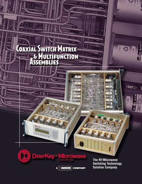
The RF/<strong>Microwave</strong><br />
<strong>Switch</strong>ing Technology<br />
Solution Company
New Generation of <strong>Switch</strong> Matrices<br />
Broadband DC-18 GHz Solutions<br />
Introduction<br />
Dow-Key <strong>Microwave</strong>, a leader in the design and manufacture of switching<br />
products, acquired its <strong>Matrix</strong> line in 1999. Since that time, the line has<br />
expanded to include both standard and custom matrices supporting the<br />
aerospace, military and communication industries for both signal routing and<br />
ATE applications. All Dow-Key matrices incorporate Control Area Network<br />
bus (CANbus) serial communication in their design. This technology allows<br />
for fast system integration and flexibility for today’s complex system requirements.<br />
Although this brochure only showcases a few established designs,<br />
Dow-Key welcomes inquiries for all matrix applications.<br />
Internal CANbus-based control technology includes the following features:<br />
• Self-identification and configuration of all switchable devices<br />
• Multiple control interfaces<br />
• Field upgradeable operating software.<br />
• Flexibility to add more than 200 switchable devices to the system.<br />
As an option, the switch matrix can provide signal conditioning by incorporating<br />
amplifiers, filters, attenuators, couplers, and other components.
Open Control Architecture<br />
A considerable number of<br />
external CANbus devices<br />
can be added to the <strong>Matrix</strong>.<br />
During system start up, the<br />
internal controller identifies<br />
CANbus devices and initiates<br />
control via communication<br />
interfaces.
New Generation of <strong>Switch</strong> Matrices<br />
Broadband DC-18 GHz Solutions<br />
Overview of Standard Products<br />
10X10 <strong>Coaxial</strong><br />
<strong>Switch</strong> <strong>Matrix</strong><br />
Models:<br />
4101-GPIB<br />
4101-ENET<br />
4101-EWEB<br />
A compact and high performance solution, the model 4101 provides a Non-blocking<br />
<strong>Switch</strong> <strong>Matrix</strong> configured as a 5X5 up to a 10X10 in a small 4U (7 inch) high full rack<br />
enclosure . Available options include:<br />
• Redundant power supplies<br />
• N and BNC connectors.<br />
1x100 <strong>Switch</strong>ing<br />
System<br />
Models:<br />
4201-GPIB<br />
4201-ENET<br />
4201-EWEB<br />
This unit houses up to 11 single pole ten throw (SP10T) switches configured (in its<br />
maximum capacity) as a 1X100 Multiplexer in a 4U (7 inch) high full rack enclosure.<br />
Back panel mounted switches reduce the number of internal RF/<strong>Microwave</strong> cables<br />
and eliminate output cables. The switching system is offered with a reduced number<br />
of switches starting from 1X10.
11SP10T<br />
<strong>Switch</strong> Unit<br />
Models:<br />
4301-GPIB<br />
4301-ENET<br />
4301-EWEB<br />
The model 4301 supports up to eleven individual SP10T switches in a<br />
4U (7 inch) high full rack enclosure. Easy access to RF Input/Output<br />
connectors from the back panel permits easy maintenance and reconfiguration.<br />
4SP10T<br />
<strong>Switch</strong> Unit<br />
Models:<br />
4104-GPIB<br />
4104-ENET<br />
4104-EWEB<br />
A compact switching solution, model 4104 supports up to four individual SP10T<br />
switches in a 1U (1.75 inch) high full rack enclosure. Trouble-free access to RF<br />
Input/Output connectors from the back panel permits easy maintenance and<br />
reconfiguration.
New Generation of <strong>Switch</strong> Matrices<br />
Broadband DC-18 GHz Solutions<br />
Overview of Standard Products<br />
<strong>2X8</strong> <strong>Coaxial</strong><br />
<strong>Switch</strong> <strong>Matrix</strong><br />
Models:<br />
4401-GPIB<br />
4401-ENET<br />
4401-EWEB<br />
The model 4401 is a Non-blocking <strong>Switch</strong> <strong>Matrix</strong> configured as a 2X4 to <strong>2X8</strong><br />
unit in a 3U (5.25 inch) high full rack enclosure. Available options include N<br />
and BNC connectors.<br />
2x8 Low Loss <strong>Coaxial</strong><br />
<strong>Switch</strong> <strong>Matrix</strong><br />
Models:<br />
4402-GPIB<br />
4402-ENET<br />
4402-EWEB<br />
The model 4401 is a Non-blocking <strong>Switch</strong> <strong>Matrix</strong> configured as a 2X4 to <strong>2X8</strong><br />
system in a 3U (5.25 inch) high full rack enclosure. Back panel mounted<br />
switches minimize RF/<strong>Microwave</strong> cabling losses providing an Insertion Loss<br />
of less than 1 dB @ 18 GHz.
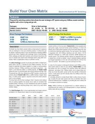
Typical <strong>Switch</strong> <strong>Matrix</strong> Designs<br />
6 5 4 3 2 1<br />
OUTPUTS<br />
6 X SP6T<br />
CANBUS SWITCH<br />
1<br />
2<br />
3<br />
4<br />
Non-blocking<br />
• Connects any input to any output<br />
• Simultaneous active multiple channels<br />
Advantages:<br />
• Wide Bandwidth<br />
• Low Insertion Loss<br />
• High Isolation<br />
• Bi-Directional<br />
Disadvantages:<br />
• Any input can be connected to<br />
only one output at a time<br />
5<br />
Figure 1. 6 x 6 non-blocking matrix<br />
6<br />
INPUTS<br />
6 X SP6T<br />
CANBUS SWITCH<br />
OUTPUTS<br />
6 X SP6T<br />
POWER DIVIDER<br />
INPUTS<br />
8 X WILKINSON<br />
POWER DIVIDER<br />
Fan-out<br />
• Connects any input to any output simultaneously<br />
• Multiple, simultaneous active channels<br />
• Can connect any input to all outputs simultaneously<br />
Advantages:<br />
• Interconnect flexibility<br />
• High throughput<br />
Disadvantages:<br />
• Bandwidth limited by power divider<br />
• Higher insertion loss<br />
• Low isolation between outputs connected<br />
to the same input<br />
Figure2. 6 x 6 fan-out matrix<br />
OPTIONAL<br />
6 X LNA<br />
OUTPUTS<br />
9 X SP6T<br />
CANBUS SWITCH<br />
INPUT<br />
SP6T<br />
CANBUS SWITCH<br />
1xn<br />
• Can connect one input to any output<br />
Advantages:<br />
• Wide bandwidth<br />
• High isolation<br />
• Bi-directional<br />
Figure 3. 1 x n matrix<br />
Disadvantages:<br />
• Can connect to only one output at a time
Reconfigurable <strong>Switch</strong> <strong>Matrix</strong> (RMS)<br />
Models:<br />
4700-GPIB<br />
4700-ENET<br />
4700-EWEB<br />
Dow-Key’s Reconfigurable <strong>Matrix</strong><br />
System (RMS) is offered as a<br />
solution for the new generation<br />
of reconfigurable and expandable<br />
state-of-the-art (ATE) test systems. It provides<br />
the user with the capability to configure the interconnection<br />
of all internal components and add additional components to<br />
a test system when needed, thereby extending its functionality.<br />
While the internal control interface is CANbus-based, the RMS software<br />
makes it transparent for users when a different control interface<br />
(e.g. GPIB, Ethernet, RS-232, and RS-485) is specified.<br />
The internal operating system is specifically designed to universally<br />
accept any CANbus components when expansion is required. There is<br />
no need for any additional upgrades to the operating system. During the<br />
initiation process (when powered up), the operating system identifies all<br />
CANbus components and opens communication control channels.<br />
Dow-Key <strong>Microwave</strong> offers full technical support for the system<br />
integration process.
Hardware Configuration<br />
CANBus<br />
<strong>Switch</strong>es<br />
RMS Base<br />
• Standard 19”, 4U cage with the following options:<br />
• LCD Display<br />
• Key Pad<br />
• Power Supply<br />
• Translator Cards<br />
• GPIB including RS232 and RS485<br />
• Ethernet including RS232<br />
CANBus <strong>Switch</strong><br />
Blocks and<br />
Bracketry<br />
Programmable<br />
Attenuators<br />
The RMS consists of:<br />
• Universal <strong>Matrix</strong> Cage<br />
• Translator Card for various standard control interfaces<br />
• Electro-mechanical <strong>Switch</strong>es and other switchable components with CANbus Interface<br />
• Standard mounting hardware to support the system mechanical integration.<br />
Steps in RMS system selection and information:<br />
• Provide a block diagram and specifications describing the functional requirements<br />
of the switching network<br />
• Dow-Key selects required hardware and components and submits to customer for approval<br />
• Customer chooses either Dow-Key providing the entire “turn-key” solution or procures<br />
a RMS kit.<br />
• In addition to end item hardware, the “turn-key” solution also includes product design,<br />
design verification and manufacturing and test documentation.<br />
• The RMS kit includes as a minimum; universal matrix cage, all CANbus controllable<br />
devices and associated hardware and software. The flexibility of the RMS system allows<br />
adding or removing CANbus components. The system can control over 100 components<br />
connected to one control bus.
New Generation of <strong>Switch</strong> Matrices<br />
Broadband DC-18 GHz Solutions<br />
General Specifications<br />
RF Specifications<br />
Dow-Key Model<br />
4101 - Series<br />
4201 - Series<br />
4301 - Series<br />
4104 - Series<br />
4401 - Series<br />
4402 - Series<br />
Frequency Range<br />
dB<br />
DC - 8<br />
8 - 12<br />
12 - 18<br />
DC - 8<br />
8 - 12<br />
12 - 18<br />
DC - 8<br />
8 - 12<br />
12 - 18<br />
DC - 8<br />
8 - 12<br />
12 - 18<br />
DC - 8<br />
8 - 12<br />
12 - 18<br />
DC - 8<br />
8 - 12<br />
12 - 18<br />
VSWR<br />
1.4 : 1<br />
1.6 : 1<br />
1.8 : 1<br />
1.4 : 1<br />
1.6 : 1<br />
1.8 : 1<br />
1.4 : 1<br />
1.6 : 1<br />
1.8 : 1<br />
1.4 : 1<br />
1.6 : 1<br />
1.8 : 1<br />
1.4 : 1<br />
1.5 : 1<br />
1.7 : 1<br />
1.4 : 1<br />
1.5 : 1<br />
1.7 : 1<br />
Isolation<br />
dB<br />
70<br />
60<br />
50<br />
70<br />
60<br />
50<br />
70<br />
60<br />
50<br />
70<br />
60<br />
50<br />
70<br />
60<br />
50<br />
70<br />
60<br />
50<br />
Insertion Loss<br />
dB<br />
3<br />
4.5<br />
6<br />
3<br />
4.5<br />
6<br />
0.4<br />
0.5<br />
0.8<br />
0.4<br />
0.5<br />
0.8<br />
1<br />
2<br />
3<br />
0.6<br />
0.8<br />
1<br />
Power Handling<br />
W<br />
80<br />
60<br />
40<br />
80<br />
60<br />
40<br />
80<br />
60<br />
40<br />
80<br />
60<br />
40<br />
80<br />
60<br />
40<br />
80<br />
60<br />
40<br />
Impedance<br />
OHMS<br />
50<br />
50<br />
50<br />
50<br />
50<br />
50<br />
RF Connectors<br />
SMA Female<br />
SMA Female<br />
SMA Female<br />
SMA Female<br />
SMA Female<br />
SMA Female<br />
Translator Cards<br />
Model\Translator Card<br />
GPIB/RS-232-RS-485/CAN<br />
Ethernet/RS-232/CAN<br />
GPIB Version<br />
Standard<br />
Optional<br />
ENET Version<br />
Optional<br />
Standard<br />
EWEB Version<br />
Optional<br />
Standard<br />
Control Interfaces<br />
IEEE-488 general purpose interface bus including SCPI Standard<br />
IEEE-802.3 Ethernet communication bus including SCPI Standard<br />
CANbus interface (version 2.0B passive)<br />
RS-232 and RS-485 including SCPI Standard<br />
ENET Model Includes<br />
TCP, IP, UDP, ARP, DHCP, ICMP, SMTP. <strong>Matrix</strong> is controlled over TCP/IP using the<br />
SCPI standard.<br />
EWEB Model Includes<br />
TCP, IP, UDP, ARP, DHCP, ICMP, SMTP, FTP, HTTP. <strong>Matrix</strong> is controlled over<br />
TCP/IP using the SCPI standard. For control by HTTP and any web browser, a<br />
web page is stored inside the matrix using FTP.<br />
Other Specifications<br />
Model<br />
<strong>Switch</strong> Type<br />
<strong>Switch</strong>ing Speed<br />
Operating Temperature<br />
Power Supply<br />
4101<br />
Normally Open<br />
50 ms<br />
0 - 50 C<br />
4201<br />
Normally Open<br />
50 ms<br />
0 - 50 C<br />
4301<br />
Normally Open<br />
50 ms<br />
0 - 50 C<br />
4104<br />
Normally Open<br />
50 ms<br />
0 - 50 C<br />
4401<br />
Latching<br />
60 ms<br />
0 - 50 C<br />
Input Voltage 85 - 232 VAC, 47 - 440 Hz (Optional Redundant Power Supply available)<br />
4402<br />
Latching<br />
60 ms<br />
0 - 50 C
General Specifications<br />
Outline Dimensions<br />
A<br />
B<br />
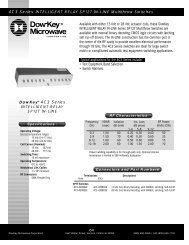
4101 - Series<br />
10X10 <strong>Coaxial</strong> <strong>Switch</strong> <strong>Matrix</strong><br />
4 U Rack Mountable Chassis<br />
A<br />
B<br />
4301 - Series<br />
11XSP10T <strong>Switch</strong>ing System<br />
4 U Rack Mountable Chassis<br />
A<br />
B<br />
4201 - Series<br />
1X100 <strong>Switch</strong>ing System<br />
4 U Rack Mountable Chassis<br />
A<br />
A<br />
B<br />
B<br />
4104 - Series<br />
4XSP10T <strong>Switch</strong>ing System<br />
1 U Rack Mountable Chassis<br />
4401 - Series<br />
<strong>2X8</strong> <strong>Coaxial</strong> <strong>Switch</strong> <strong>Matrix</strong><br />
3 U Rack Mountable Chassis<br />
A<br />
B<br />
4402 - Series<br />
<strong>2X8</strong> <strong>Coaxial</strong> <strong>Switch</strong> <strong>Matrix</strong><br />
3 U Rack Mountable Chassis<br />
DIM<br />
4101<br />
4301<br />
4201<br />
4104<br />
4401<br />
4402<br />
A<br />
19.02<br />
19.02<br />
19.02<br />
19.02<br />
19.02<br />
19.02<br />
B<br />
7.00<br />
7.00<br />
7.00<br />
1.75<br />
(2.00)<br />
5.25<br />
5.25<br />
DEPTH<br />
21.81<br />
21.81<br />
21.81<br />
21.81<br />
5.00<br />
5.00
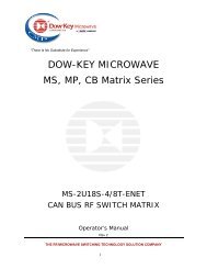
Custom Matrices & Multifunction Assemblies<br />
Dow-Key PN 5010<br />
Receiver Test Interface<br />
Frequency Range:<br />
0.7 -2.3 GHz<br />
Application:<br />
ATE Wireless<br />
Dow-Key PN 5005<br />
ATE Interface Network Box<br />
Frequency Range:<br />
0.8 – 4.0 GHz<br />
Application:<br />
ATE (3G Base<br />
Dow-Key PN 5020<br />
464 SRMU RF Output Module<br />
Frequency Range:<br />
0.5 – 18 GHz<br />
Application:<br />
Military Test System<br />
Dow-Key PN 5002<br />
6 Sector Environmental and<br />
Production Cross-Coupling Unit<br />
Frequency Range:<br />
1.5 – 2.7 GHz<br />
(0.01 – 13.0 GHz)<br />
Application:<br />
ATE (3G Base Station Testing)<br />
4822 McGrath Street • Ventura, CA 93003-5641<br />
Tel: (805) 650-0260 • Fax: (805) 650-1734<br />
Visit us at www.dowkey.com