
Create successful ePaper yourself
Turn your PDF publications into a flip-book with our unique Google optimized e-Paper software.
ELECTROMECHANICAL<strong>SWITCH</strong> MATRICES
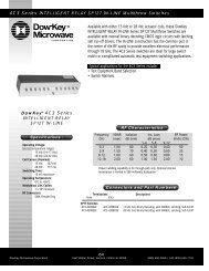
ElectromechanicalMS-Series | Multiple SwitchesMS-Series | Multiple SwitchesElectromechanical1RU Model2RU ModelApplicationThe MS-series is a switch solution populated withindividual switches to allow the user to controlmultiple coaxial switches easily through software.It gives the user the flexibility to add as many switchesas needed (limited to the size of the enclosure) onthe rear panel or inside the box starting with a 19”1RU chassis up to 4RU (and larger enclosures forcustom designs).• Switches can be mixed & matched• Terminated and non-terminated switches• Normally Open & Latching switches• Built-in firmware to add, remove and addressswitches for trouble free switch replacement• Application configuration available through“configuration file” - transferred via HTTP, USBor COM ports.• Keeps track of the life of each switch• Field upgradable firmware via boot loader(1)SpecificationsFeaturesConfigurationOperating FrequencyManual ControlMultiple Switches (bidirectional):SPDT (3) , DPDT, SP3T, SP4TSP6T, SP8T, SP10T, SP12TDC-18 GHz, DC-26.5 GHz or DC-40GHzLCD with Keypad (1RU)Touch Screen LCD (2RU-4RU)RF SpecificationsDC-18 GHz, Latching, Non-TerminatedFrequency[GHz]SPDT (3) / DPDT SwitchRemote Control ENET: Ethernet, Built-In Website,4-8 1.30 70 0.30 50RS-232 and USB port.8-12 1.40 65 0.40 35GPIB: IEEE-488, RS-232 and12-18 1.50 60 0.50 25USB port.(3)ImpedanceADD A TERMINATION TO ONE PORT OF THE DPDT <strong>SWITCH</strong> TO GET A SPDT <strong>SWITCH</strong>50-Ohm(1) Check Availability18-26.5 1.8 50 0.80 10Rear View with SP10T Switches(P/N 5x5-5208-3)DC-18 GHz, Normally Open, Non-TerminatedSP3T - SP6T Switch2RUFrequency[GHz]VSWRMax.IsolationMin. [dB]Insertion LossMax. [dB]CW PowerMax. [W]DC-3 1.2 80 0.20 1253-8 1.3 70 0.30 903RU8-12.4 1.4 60 0.40 7512.4-18 1.5 60 0.50 60(P/N 4x1KL-420822N, 4x1KL-420823N)DC-26.5 GHz, Latching, Non-Terminated/Terminated SP3T - SP6T Switch4RUFrequency[GHz]VSWRMax.IsolationMin. [dB]Insertion LossMax. [dB]CW PowerMax. [W]DC-4 1.2 80 0.20 1004-8 1.3 75 0.30 508-12.4 1.4 70 0.40 3512.4-18 1.5 60 0.50 25Part Number SelectorVSWRMax.IsolationMin. [dB]Insertion LossMax. [dB](P/N 411L-420832N)CW PowerMax. [W]DC-1 1.10 85 0.10 2001-4 1.20 80 0.20 100Relay Type Coaxial Manual Control LCD/Keypad or Touch Screen LCDI/O Connector Type SMA Female or N Female Remote Control Ethernet or GPIB OptionSwitching Time 50 ms (incl. control delay) ENET Option Ethernet (TCP/IP), 10/100 BASE-T,Operating Life (min) 1,000,000 (cold)built-in website, manual or DHCP IPMTBF30,000-50,000 Hoursaddress assignmentOperating Temperature 0 °C to +50 °C RS-232 DB9 (f), Baud Rate1200 -115200 bpsStorage Temperature -20 °C to +70 °C USB Port Operates as a virtual RS-232Operating Humidity 10-80% non-condensing GPIB Option GPIB (IEEE-488), RS-232 and USBDimensions (max) 19” Wide rack mountCommands/Syntax Dow-Key SCPI commands15.25” (1U-2U) & 18.5” (3U- FuseAccessible/replaceable on the rear4U) Depth (w/o handles) AC Power Supply 110-240 VAC, 50-60 Hz1U to 4U Height (1.75” to 7.00”) Cooling / Venting Fans as required with 2U-4U modelsWeightVaries per part number(1)(2)MS1U 18 S 4 / 61U = 1.75” 12 = DC-12.5 GHz N = N female 1 = 1 Switch 2 = SPDT (3) T = 2W Termination ENET = Ethernet2U = 3.50” 18 = DC-18 GHz S = SMA female 2 = 2 Switches X = DPDT Transfer (otherwise leave it GPIB = GPIB3U = 5.25” 26 = DC-26.5 GHz (1) K = 2.9 mm 3 = 3 Switches 3 = SP3T blank)4U = 7.00” 40 = DC-40 GHz (1) . . . 4 = SP4T8 = 8 Switches 6 = SP6T8 = SP8T10 = SP10T12 = SP12TENETChassis Height Frequency Connector Quantity (2) Switch Type TerminatedNot available with all switch types.For 9 and more switches, we can mount inside the chassis.See Appendix A for details.Remote Control1-2Dow-Key <strong>Microwave</strong> • www.dowkey.com • 800.266.3695AS9100/ISO-9001: 2008 CertifiedAS9100/ISO-9001: 2008 Certified Dow-Key <strong>Microwave</strong> • www.dowkey.com • 800.266.36951-3
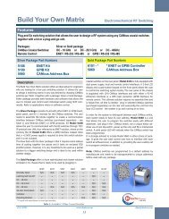
ElectromechanicalMS-Series | Multiple SwitchesMS-Controller | Build Your Own SolutionElectromechanicalRF Specifications (cont.)DC-18 GHz, Normally Open, Non-TerminatedFrequency[GHz]DC-18 GHz, Normally Open, Non-TerminatedFrequency[GHz]VSWRMax.VSWRMax.IsolationMin. [dB]IsolationMin. [dB]Insertion LossMax. [dB]Insertion LossMax. [dB]SP8T SwitchCW PowerMax. [W]DC-4 1.25 70 0.20 1004-8 1.35 65 0.30 708-12.4 1.40 60 0.40 6012.4-16 1.50 60 0.60 5016-18 1.80 55 0.80 45DC-18 GHz, DC-26.5 GHz, Latching, TerminatedFrequency[GHz]VSWRMax.IsolationMin. [dB]Insertion LossMax. [dB](P/N 581-520802N)(P/N 581-420853N, 581K-420853N)SP8T SwitchCW PowerMax. [W]DC-4 1.20 80 0.20 1004-8 1.30 75 0.30 908-12.4 1.40 70 0.40 7512.4-18 1.50 60 0.50 6018-26.5 1.80 55 0.80 45(P/N 5A1-520802N)SP10T SwitchCW PowerMax. [W]DC-4 1.20 70 0.20 1004-8 1.30 65 0.30 708-12.4 1.40 60 0.40 6012.4-18 1.60 55 0.60 50Front ViewRear View with Ethernet Control InterfaceApplicationThe MS-6101 controller offers an ideal switch setupallowing anyone to build their own matrix solution byplugging-in Dow-Key CAN bus controlled switchesonto the rear panel. The controller converts CANinterface to either Ethernet or GPIB interface.The 1RU controller is outfitted with 24 RJ11 ports onthe back to support 24 CAN bus switches and can beexpanded to support additional switches as neededby adding patch panels.CAN bus switches, RJ11-X cables, RJ11 patch panel(for expansion) and secondary power supply arepurchased separately.Input power: The input AC power supply will downconvert and distribute DC voltage to all the switchesand sub-component (including the patch panel ifneeded).FeaturesControllerConfigurationPower SupplyManual ControlRemote ControlsWhat You Need1.2.3.4.ExpansionAllows the user to controlDow-Key RF switchesSupports 24 CAN bus switches viaRJ11 connectors110-240 VAC, 100W max.LCD with KeypadENET: Ethernet, Built-In Website,RS-232 and USB port.GPIB: IEEE-488, RS-232 andUSB port.• Supports > 24 switches• 2nd power supplyOne MS-6101 controllerSelect any CAN bus controlled switches per Table 1.Get RJ11-6 cable for each switch to plug-in to the controllerIf more than 24 switches are need, add RJ11 patch panel board foreach additional 11 switches and use RJ11-4 cables. Also, checkwith Dow-Key if secondary power supply is needed.DC-18 GHz, Normally Open Non-Term. / Latching Term.Frequency[GHz]VSWRMax.IsolationMin. [dB]Insertion LossMax. [dB]SP12T SwitchCW PowerMax. [W]DC-4 1.20 70 0.20 1004-8 1.40 65 0.40 508-12.4 1.50 60 0.60 3512.4-18 1.80 60 0.80 25SEE APPENDIX C FOR <strong>SWITCH</strong> SCHEMATICS(P/N 5C1-520802N, 5C1-420853N)FOR <strong>SWITCH</strong>ES MOUNTED INSIDE A CHASSIS,CONTACT DOW-KEY MICROWAVE FOR RF SPECIFICATIONS.We reserve the right to alter, amend or replace any specifications at our sole discretion and without prior notice.MS-6101 SpecificationsI/O Connector Type 24x RJ11-6 Manual Control LCD with KeypadRoHS Compliant Yes Remote Control Ethernet or GPIB OptionEMI Shielded PortsRJ45, USB, RS-232, GPIB, MS-6101-ENET Ethernet (TCP/IP), 100/100 BASE-T,RJ11-6, CAN busHTTP (built-in website,) manual orMTBF30,000-50,000 HoursDHCP IP address assignmentOperating Temperature 0 °C to +50 °C RS-232 DB9 (f), Baud Rate1200 -115200 bpsStorage Temperature -20 °C to +70 °C USB Port Operates as a virtual RS-232Operating Humidity 10-80% non-condensing MS-6101-GPIB GPIB (IEEE-488), RS-232 and USBDimensions (max) 19” Wide rack mount Commands/Syntax Dow-Key SCPI commands15.25” Depth Switching Time 50 ms (including control delay)1U Height (1.75”) AC Power Supply 110-240 VAC, 50-60 HzWeight (approx) 10 lbs Fuse Accessible/replaceable on the rear1-4Dow-Key <strong>Microwave</strong> • www.dowkey.com • 800.266.3695AS9100/ISO-9001: 2008 CertifiedAS9100/ISO-9001: 2008 Certified Dow-Key <strong>Microwave</strong> • www.dowkey.com • 800.266.36951-5
ElectromechanicalMS-Controller | Build Your Own SolutionMS-Control Kit | Build Your Own SolutionElectromechanicalLIST OF CAN BUS <strong>SWITCH</strong>ES<strong>SWITCH</strong> TYPE PART NUMBER FREQUENCY ACTUATOR RF CONNECTOR TERMINATEDSPDT (3) / DPDT 411C-420832N DC-18 GHz LATCHING SMA NOSPDT (3) / DPDT 411CY-421132N DC-40 GHz LATCHING 2.9 mm (K) NOSP3T 535-5208-3 DC-18 GHz NORMALLY OPEN SMA NOSP3T 431KL-420822N DC-26.5 GHz LATCHING SMA NOSP3T 431KL-420823N DC-26.5 GHz LATCHING SMA YESSP4T 545-5208-3 DC-18 GHz NORMALLY OPEN SMA NOSP4T 441KL-420822N DC-26.5 GHz LATCHING SMA NOSP4T 441KL-420823N DC-26.5 GHz LATCHING SMA YESSP6T 565-5208-3 DC-18 GHz NORMALLY OPEN SMA NOSP6T 461KL-420822N DC-26.5 GHz LATCHING SMA NOSP6T 461KL-420823N DC-26.5 GHz LATCHING SMA YESSP8T 581-520802N DC-18 GHz NORMALLY OPEN SMA NOSP8T 581K-520802N DC-26.5 GHz NORMALLY OPEN SMA NOSP8T 581K-420853N DC-26.5 GHz LATCHING SMA YESSP10T 5A1-520802N DC-18 GHz NORMALLY OPEN SMA NOSP12T 5C1-520802N DC-18 GHz NORMALLY OPEN SMA NOSP12T 5C1-420853N DC-18 GHz LATCHING SMA YES(3) ADD A TERMINATION TO ONE PORT OF THE DPDT <strong>SWITCH</strong> TO GET A SPDT <strong>SWITCH</strong>ALL CANBUS <strong>SWITCH</strong>ES USE 12 VDC COILS. IF <strong>SWITCH</strong> USED WITH MS-6101 CONTROLLER, THE POWERSUPPPLY WILL DOWN CONVERT VAC TO 12 VDC.We reserve the right to alter, amend or replace any specifications at our sole discretion and without prior notice.CAN Bus Switch SpecificationsList of Part NumbersTABLE 1Ethernet/GPIB Controller Board(switches are not included)Application / What you NeedThe MS-ENET and MS-GPIB kits are low budget solutionsfor users who are comfortable to assemble components ontheir own to build a RF switch solution.Depending of the type of control, there are two kits available.Either kit consists of an Ethernet/GPIB control board and12x RJ11-6 cables (to be used with CAN bus switches),where some assembly is required.RF switches are not included and are purchased separately.Refer to the MS-6101 Controller page for a list of availableDow-Key CAN bus switches (Table 1).MS-ENET: This kit allows the user to control switchesvia Ethernet (TCP/IP with manual or DHCP IP addressassignment), RS-232, USB and HTTP (built-in website).MS-GPIB: This kit offers the user GPIB (IEEE-488),RS-232 and USB controls.Specifications / Part NumbersFeaturesMS-ENETMS-GPIBKit provides software controls viaEthernet, Web-interface, RS-232and USB port. It includes PCBboard and RJ11-4 cables.Kit provides software controls viaGPIB (IEEE-488), RS-232 and USBport. It includes PCB board andRJ11-4 cables.Kit Components Include: • 1 PCB board for controlling 20•Dow-Key CAN bus switches12x RJ11-4 cablesExpansionSupport >20 switchesMS-Control kits are offered with Dow-Key SCPI commands thatgives the user the flexibility to control the switches either directlyvia GPIB or TCP/IP protocols. These commands can also easilybe embedded into customer designed software programs as a“string”.Application:Best used for ATE, test-bench and system integratedapplications.What You Need:1. Select either MS-ENET or MS-GPIB kit2. Choose any CAN bus controlled switches per Table 13. Purchase additional RJ11-6 cable if 13 or more switchesare needed.4. If more than 20 switches are required, purchase RJ11 patchpanel board along with RJ11-4 cables. The board support11 additional switches and can be cascaded to support upto 256 switches.Relay Type Coaxial ControllerImpedance 50-Ohm MS-6101-ENET Ethernet with LCD/KeypadI/O Connector Type SMA Female or 2.9 mm Female MS-6101-GPIB GPIB with LCD/KeypadOperating Frequency DC-18 GHz, DC-26.5 GHz or RF SwitchesDC-40 GHzSee Table 1 for part numbersOperating Life (min) 1,000,000 (cold) Additional ComponentsControl Interface CAN Bus control 41099-072-X RJ11-6 cable of X inches lengthCoil Voltage 12 Vdc 41099-069-X RJ11-4 cable of X inches lengthProgram & Control Through the MS-6101 cont- 41054-028 RJ11 Patch panel boardroller you can add/remove andassign unique CAN ID addressto the switch, and track the life ofeach switch.40090-003 2W, 50-Ohm, TerminationGeneralEthernet Kit (Part Number MS-ENET)ENET/GPIB ControlRJ-45 portEthernet (TCP/IP), 10/100 BASE-T,3.0” W x 7.0” LBoard Dimensions:HTTP, manual/DHCP IP assignmentI/O Connector Type 20x RJ11-4 RS-232 Port DB9 (F), Baud Rate1200 -115200 bpsMTBF 30,000-50,000 Hours USB Port Operates as a virtual RS-232Control Board Power +12 Vdc 41099-069-36 12x 3 FT RJ11-4 cables (unassembled)Current Draw (max) 300 mA (excl. switches) GPIB Kit (Part Number MS-GPIB)Operating Temperature 0 °C to +50 °C GPIB Port IEEE-488, 24-pin female (centronics)Storage Temperature -20 °C to +70 °C USB Port Operates as a virtual RS-232Operating Humidity 10-80% non-condensing 41099-069-36 12x 3 FT RJ11-4 cables (unassembled)SoftwareAdditional Part NumbersCommands/Syntax Dow-Key SCPI commands 41099-069-X RJ11-4 cable of X inches lengthSwitching Time 50 ms (incl. control delay) 41054-028 RJ11 Patch Panel1-6Dow-Key <strong>Microwave</strong> • www.dowkey.com • 800.266.3695AS9100/ISO-9001: 2008 CertifiedAS9100/ISO-9001: 2008 Certified Dow-Key <strong>Microwave</strong> • www.dowkey.com • 800.266.36951-7
ElectromechanicalMP-Series | MultiplexerMP-Series | MultiplexerElectromechanical3RU ModelApplication Rear View Samples (2)MP-series is a multiplexer with the capability toswitch one input to as many as 143 outputs. Theinput/output ports are bidirectional.Design starts from 1x13 to 1x143 (1RU-4RUenclosure) and can be customized to support alarger configuration. It is available with maximumfrequency at 18 GHz or 26.5 GHz, both terminatedand non-terminated options along with SMA orN-type connectors.Software Features:• Built-in firmware to add, remove and addressswitches for trouble free switch replacement• Application configuration available through“configuration file” - transferred via HTTP, USBor COM ports.• Keeps track of the life of each switch• Field upgradable firmware via boot loader(1)(1) Check AvailabilityRF SpecificationsFeaturesSwitch Configuration 1xN bidirectionalTHE RF PERFORMANCE(2) The exact port locations may be differentWe reserve the right to alter, amend or replace any specifications at our sole discretion and without prior notice.Terminated & Non-TerminatedFOR ≤1x70DC-18 GHz, Non-Terminated, SMA1x13 to 1x84Maximum 1x143IS SLIGHTLYFrequency VSWR Isolation Insertion Loss CW PowerOperating Frequency DC-18 GHz or DC-26.5 GHzBETTER.[GHz]Max. Min. [dB] Max. [dB] Max. [W]Manual Control LCD with Keypad (1RU)DC-8 1.4 80 1.0 90Touch Screen LCD (2RU-4RU)8-12 1.7 80 1.5 60Remote Control ENET: Ethernet, Built-In Website,RS-232 and USB port.12-16 1.9 80 2.0 45GPIB: IEEE-488, RS-232 andUSB port.16-18 2.4 80 3.0 35Impedance50-OhmTHE RF PERFORMANCE SP10T AND/OR SP12T <strong>SWITCH</strong>ES MOUNTED INSIDE THE ENCLOSUREFOR ≤1x100DC-18 GHz, Non-Terminated, SMA1X85 to 1X120IS SLIGHTLYBETTER.Frequency VSWR Isolation Insertion Loss CW Power[GHz]Max. Min. [dB] Max. [dB] Max. [W]2RUDC-4 1.4 80 2.5 90(1x30)4-8 1.7 80 4.0 608-12 1.9 80 5.0 453RU12-18 2.4 80 6.5 35(1x50)SP12T <strong>SWITCH</strong>ES MOUNTED INSIDE THE ENCLOSUREDC-18 GHz, Non-Terminated, SMA1x121 to 1x143Frequency VSWR Isolation Insertion Loss CW Power[GHz]Max. Min. [dB] Max. [dB] Max. [W]4RUDC-4 1.4 80 2.0 90(1x100)4-8 1.7 80 3.5 608-12 2.0 80 4.5 4512-18 2.4 80 5.5 35SEE APPENDIX B FOR MORE RF DATA & APPENDIX C FOR <strong>SWITCH</strong> SCHEMATICSSpecificationsRelay Type Coaxial Manual Control LCD/Keypad or Touch Screen LCDI/O Connector Type SMA Female or N Female Remote Control Ethernet or GPIB OptionSwitching Time 50 ms (incl. control delay) ENET Option Ethernet (TCP/IP), 10/100 BASE-T,Operating Life (min) 1,000,000 (cold)built-in website, manual or DHCP IPMTBF30,000-50,000 Hoursaddress assignmentOperating Temperature 0 °C to +50 °C RS-232 DB9-F, Baud Rate1200 -115200 bpsStorage Temperature -20 °C to +70 °C USB Port Operates as a virtual RS-232Operating Humidity 10-80% non-condensing GPIB Option GPIB (IEEE-488), RS-232 and USBDimensions (max) 19” Wide rack mountCommands/Syntax Dow-Key SCPI commands15.25” (1U-2U) & 18.5” (3U- FuseAccessible/replaceable on the rear4U) Depth (w/o handles) AC Power Supply 110-240 VAC, 50-60 Hz1U to 4U Height (1.75” to 7.00”) Cooling / Venting Fans as required with 2U-4U modelsWeightVaries per part numberPart Number SelectorMP3U 18 S 1001U = 1.75” 18 = DC-18 GHz N = N female 1 = 1 Output T = 2W Termination ENET = Ethernet2U = 3.50” 26 = DC-26.5 GHz S = SMA female 2 = 2 Outputs (otherwise leave it GPIB = GPIB3U = 5.25” 3 = 3 Outputs blank)4U = 7.00” . . .ENETChassis Height Frequency Connector Outputs (1) Terminated Remote Control143 = 143 Outputs(1) Maximum outputs vary per following parameters:For DC-18GHz Switch: Maximum 143 outputs (Non-Terminated & SMA)Maximum 132 outputs (Terminated & SMA)Maximum 47 outputs (Non-Terminated or Terminated & N)For DC-26.5GHz Switch: Maximum 64 outputs (Non-Terminated or Terminated & SMA)1-8Dow-Key <strong>Microwave</strong> • www.dowkey.com • 800.266.3695AS9100/ISO-9001: 2008 CertifiedAS9100/ISO-9001: 2008 Certified Dow-Key <strong>Microwave</strong> • www.dowkey.com • 800.266.36951-9
ElectromechanicalCB-Series | CrossbarCB-Series | CrossbarElectromechanicalFeaturesSwitch Configuration 2x2 up to 12x12SEE APPENDIX C(1) Check Availability We reserve the right to alter, amend or replace any specifications at our sole discretion and without prior notice.Terminated & Non-TerminatedFOR <strong>SWITCH</strong>DC-18 GHz, Non-Terminated, SMA or N2x2 to 10x10ConfigurationNon-Blocking CrossbarSCHEMATICSFrequencyIsolation Insertion Loss CW PowerOperating Frequency DC-18 GHz or DC-26.5 GHzVSWR[GHz][dB][dB][W]Manual Control LCD with Keypad (1RU)Touch Screen LCD (2RU-4RU)DC-44-81.301.3580802.03.09060ENET: Ethernet, Built-In Website,Remote Control8-12 1.45 80 3.5 45RS-232 and USB port.12-16 1.55 80 4.0 40GPIB: IEEE-488, RS-232 andUSB port.16-18 1.80 80 5.0 35CB-3U18S-6X8-ENETImpedance50-OhmSP12T NORMALLY OPEN <strong>SWITCH</strong>ESApplication Rear View Samples (2)DC-18 GHz, Non-Terminated, SMA or N11x11 to12x12FrequencyIsolation Insertion Loss CW PowerVSWRFor more complex test setups and signal switching,[GHz][dB][dB][W]2RUthe CB-series crossbar matrix is an excellent choice.DC-4 1.30 80 2.0 90It allows testing of multiple UUT/DUT (units/devices4-8 1.45 80 3.5 60under test) with many input/output signals or high8-12 1.55 80 4.0 45speed communication buses without having toconnect and disconnect them from the setup.3RU12-16 1.80 80 4.5 4016-18 2.00 80 5.5 35A crossbar system can route any input signal to anyoutput port such that the path between the I/O portsSP10T AND/OR SP12T NORMALLY OPEN/FAILSAFE <strong>SWITCH</strong>ESis unique at any given time.DC-18 GHz, Terminated, SMA or N11Tx12 /12x11T /11Tx11T (MAX)FrequencyIsolation Insertion Loss CW PowerSoftware Features:VSWR• Built-in firmware to add, remove and address4RU[GHz][dB][dB][W]switches for trouble free switch replacementDC-4 1.30 80 2.0 90• Application configuration available through4-8 1.45 80 3.5 60“configuration file” - transferred via HTTP, USB8-12 1.65 80 4.0 45or COM ports.12-16 1.80 80 4.5 40• Keeps track of the life of each switch• Field upgradable firmware via boot loader(1)16-18 2.00 80 5.5 35CAN Bus SpecificationsRelay Type Coaxial, Normally Open Manual Control LCD/Keypad or Touch Screen LCDI/O Connector Type SMA Female or N Female Remote Control Ethernet or GPIB OptionSwitching Time 50 ms (incl. control delay) ENET Option Ethernet (TCP/IP), 10/100 BASE-T,Operating Life (min) 1,000,000 (cold)built-in website, manual or DHCP IPMTBF30,000-50,000 Hoursaddress assignmentOperating Temperature 0 °C to +50 °C RS-232 DB9-F, Baud Rate1200 -115200 bpsStorage Temperature -20 °C to +70 °C USB Port Operates as a virtual RS-232Operating Humidity 10-80% non-condensing GPIB Option GPIB (IEEE-488), RS-232 and USBDimensions (max) 19” Wide rack mountCommands/Syntax Dow-Key SCPI commands15.25” (1U-2U) & 18.5” (3U- FuseAccessible/replaceable on the rear4U) Depth (w/o handles) AC Power Supply 110-240 VAC, 50-60 Hz1U to 4U Height (1.75” to 7.00”) Cooling / Venting Fans as required with 2U-4U modelsWeightVaries per part numberRF SpecificationsPart Number SelectorCB1U 18 S 4 X 61U = 1.75” 18 = DC-18 GHz N = N female 1 = 1 Input T = 2W Termination 1 = 1 Output T = 2W TerminationENETChassis Height Frequency Connector Number of Inputs (1) Terminated Inputs Number of Outputs (1)2U = 3.50” 26 = DC-26.5 GHz S = SMA female 2 = 2 Inputs (otherwise leave it 2 = 2 Outputs (otherwise leave it3U = 5.25” 3 = 3 Inputs blank) 3 = 3 Outputs blank)4U = 7.00” . . . . . .(1) Maximum Inputs X Outputs per following:For DC-18GHz Switch:12 Inputs Non-Terminated X 12 Outputs Non-Terminated11 Inputs Terminated X 12 Outputs Non-Terminated12 Inputs Non-Terminated X 12 Outputs TerminatedFor DC-26.5GHz Switch: 8 Inputs Terminated X 8 Outputs Terminated12 = 12 Inputs 12 = 12 OutputsTerminated OutputsRemote ControlENET = EthernetGPIB = GPIB1-10Dow-Key <strong>Microwave</strong> • www.dowkey.com • 800.266.3695AS9100/ISO-9001: 2008 CertifiedAS9100/ISO-9001: 2008 Certified Dow-Key <strong>Microwave</strong> • www.dowkey.com • 800.266.36951-11
Electromechanical4141 | Crossbar4169 | CrossbarElectromechanicalFeaturesMaximum I/O portsConfigurationOperating FrequencyManual ControlRemote ControlImpedance2x32 bidirectionalTerminated Output portsNon-blocking CrossbarDC-18 GHzLCD with KeypadEthernet/RS-232 orGPIB/RS-23250-OhmFeaturesMaximum I/O portsConfigurationOperating FrequencyManual ControlRemote ControlImpedance10x10 bidirectionalNormally Open, Phase-MatchedTerminated Input & Output portsNon-blocking CrossbarDC-18 GHzLCD with KeypadRS-232 with Ethernet or GPIB50-Ohm4141-2/32-GPIBPart Numbers4141-2/32-ENET4141-2/32-GPIB4169-10/10-ENETPart Numbers4169-N/M-ENETN= # of Inputs / M= # of Outputs4169-N/M-GPIBApplicationRF Specifications & Rear ViewApplicationRF Specifications & Rear ViewThe 4141 Model is a bidirectional crossbar switchmatrix configured with 2 inputs and 32 outputs usingcascaded SP8T coaxial switches. The non-connectedoutput ports are terminated to 50-ohm loads.A crossbar system can route any input signal to anyoutput port such that the path between the I/O portsis unique at any given time.The switches can either be controlled via a LCD withKeypad on the front or remotely via Ethernet or GPIBalong with RS-232 serial interface.The system is best used for RF signal switchingamong multiple devices. A suggested application is touse it as an expansion port for network analyzers.SEE APPENDIX C FOR <strong>SWITCH</strong> SCHEMATICSpecificationsFrequency[GHz]4141-2/32-GPIBVSWRMax.IsolationMin. [dB]Insert. LossMax. [dB]2x32CW PowerMax. [W]DC-8 1.40 70 3.0 108-12 1.70 65 4.0 7.512-18 1.85 60 5.0 5.0Model 4169 is a bidirectional crossbar switchconfigured with maximum (10) inputs and (10)outputs - all accessible on the front - where unusedinput and output ports are internally terminated to a2W/50-ohm load and all paths are phase matched.A crossbar system can route any input signal to anyoutput port such that the path between the I/O portsis unique at any given time.This model is equipped with front panel LCD/keypaddisplay for manual and local control, and remotelyit can be controlled via RS-232 with the options ofEthernet or GPIB.It is best used for RF testing where phase matchedpaths are critical and easy access to connect/disconnect I/O ports of the UUT is required from thefront.SpecificationsFrequency[GHz]VSWRMax.IsolationMin. [dB]Insert. LossMax. [dB]10x10CW PowerMax. [W]DC-4 1.20 75 2.5 1004-8 1.35 70 3.0 808-12 1.45 65 4.5 6012-16 1.75 60 6.0 5016-18 2.00 60 6.7 404169Relay Type Latching Coaxial Manual Control 4x40 LCD with KeypadSelf-Terminating 2W, 50-Ohm Output Ports Remote Control Ethernet or GPIB OptionI/O Connector Type SMA Female ENET Option Ethernet (TCP/IP), 10/100 BASE-T,Switching Time (typ) 540 ms (incl. control delay) manual IP address assignmentOperating Life (min) 1,000,000 (cold) RS-232 DB9 Female, Baud Rates 9,600 bpsMTBF 30,000-50,000 Hours GPIB Option GPIB (IEEE-488) 24-pin (f) & RS-232Operating Temperature 0 °C to +50 °C Commands/Syntax Dow-Key SCPI commandsStorage Temperature -20 °C to +70 °C Switching Time 420 ms approx. (incl. control delay)Operating Humidity 10-80% non-condensing Fuse Accessible/replaceable on the rearDimensions (max) 19” Wide rack mount AC Power Supply 85-264 VAC, 47-63 Hz, 150 W20” Depth Cooling / Venting 2 Fans / Side-to-Side4U Height (7.00”) Weight (max) 30 lbsRelay Type Normally Open Coaxial Manual Control 4x40 LCD with KeypadPhased Matched, TerminatedRemote Control Ethernet or GPIB OptionI/O Connector Type SMA Female ENET Option Ethernet (TCP/IP), 10/100 BASE-T,Switching Time (typ) 420 ms (incl. control delay)manual IP address assignmentOperating Life (min) 1,000,000 (cold) RS-232 DB9 Female, Baud Rates 9,600 bpsMTBF 30,000-50,000 Hours GPIB Option GPIB (IEEE-488) 24-pin (f) & RS-232Operating Temperature 0 °C to +50 °C Commands/Syntax Dow-Key SCPI commandsStorage Temperature -20 °C to +70 °C Switching Time 420 ms approx. (incl. control delay)Operating Humidity 10-80% non-condensing Fuse Accessible/replaceable on the rearDimensions (max) 19” Wide rack mount AC Power Supply 85-264 VAC, 47-63 Hz, 150 W20” Depth Cooling / Venting 2 Fans / Side-to-Side4U Height (7.00’) Weight (max) 30 lbs1-12Dow-Key <strong>Microwave</strong> • www.dowkey.com • 800.266.3695AS9100/ISO-9001: 2008 CertifiedAS9100/ISO-9001: 2008 Certified Dow-Key <strong>Microwave</strong> • www.dowkey.com • 800.266.36951-13
Electromechanical4601 | Fan-Out4701 | Fan-OutElectromechanicalFeaturesInput/Output ports4x4 to 8x8 unidirectionalFeaturesInput/Output ports9x9 to 12x12 unidirectionalConfigurationNon-blocking Full Fan-OutConfigurationNon-blocking Full Fan-OutOperating Frequency1-18 GHzOperating Frequency1-18 GHzManual ControlLCD Touch ScreenManual ControlLCD Touch Screen4601-8/8-ENETRemote ControlPower SupplyEthernetRedundant power supplies4701-12/12-ENETRemote ControlPower SupplyEthernetRedundant power suppliesImpedance50-OhmImpedance50-OhmPart NumbersN= # of Inputs / M= # of OutputPart NumbersN= # of Inputs / M= # of Output4601-N/M-ENETN=M: 4x4, 5x5, 6x6, 7x7, 8x84701-N/M-ENETN=M: 9x9, 10x10, 11x11, 12x12ApplicationRF SpecificationsApplicationRF SpecificationsThe 4601 Model is an unidirectional 50-ohm Fan-Outswitch matrix configured with a maximum of 8 inputsand 8 outputs. The RF inputs are first amplifiedwith high linearity amplifiers (to compensate forthe insertion loss) and then divided using 4-waypower dividers before being routed to SP8T coaxialswitches terminated to 2W/50-ohm loads. Hence,the frequency band is limited to 1-18 GHz.A fan-out matrix divides all the RF inputs such thatit can switch any input to one or more (all) outputssimultaneously.The 4601-series is equipped with MS Windowsbased PC, removable SATA hard drive, redundantpower supplies with LED monitoring on the frontpanel. Locally it can be controlled via an LCD touchscreen and remotely with Ethernet.VSWR (max)Isolation (min)GainGain FlatnessSurvivable Input Power1dB Compression (min)3rd Order Intercept (min)2nd Order Intercept (min)Noise Figure (max)2.50:1 input & output4x4 to 8x860 dB input/input60 dB input/output60 dB output/output (different input)18 dB output/output (common input)0 dB ± 2.0 dB0.5 dB max over any “rolling” 100 MHzspan, 8.0 dB max across 1-18 GHz+20 dBm (max) no damage+5 dBm input+10 dBm+20 dBm11 dBThe 4701 Model is an unidirectional 50-ohm Fan-Out switch matrix configured with a maximum of12 inputs and 12 outputs. The RF inputs are firstamplified with high linearity amplifiers (to compensatefor the insertion loss) and then divided using 4-wayand 3-way power dividers before being routed toterminated SP12T coaxial switches with 2W/50-ohmloads. Hence, the frequency band is limited to 1-18GHz.A fan-out matrix divides all the RF inputs such thatit can switch any input to one or more (all) outputssimultaneously.The 4701-series is equipped with MS Windowsbased PC, removable SATA hard drive, redundantpower supplies with LED monitoring on the frontpanel. Locally it can be controlled via an LCD touchscreen and remotely with Ethernet.VSWR (max)Isolation (min)GainGain FlatnessSurvivable Input Power1dB Compression (min)3rd Order Intercept (min)2nd Order Intercept (min)Noise Figure (max)2.50:1 input & output9x9 to 12x1260 dB input/input60 dB input/output60 dB output/output (different input)18 dB output/output (common input)0 dB ± 2.0 dB0.5 dB max over any “rolling” 100 MHzspan, 8.0 dB max across 1-18 GHz+15 dBm (max) do damage+5 dBm input+10 dBm+20 dBm11 dBSpecificationsSpecificationsRelay Type Latching Terminated Coaxial Local Control 6.5” LCD Touch Screen (640x480)Other Components Amplifiers, Power Dividers Remote Control Ethernet TCP/IP, 10/100/1000 BASE-TI/O Connector Type N (f) inputs / SMA (f) outputs Commands/Syntax Dow-Key SCPI commandsSwitching Time (min) 300 ms (incl. control delay) Operating System Microsoft Windows 7 or laterOperating Life (cold) 1,000,000 per position RS-232 gives access to the built-in PCMTBF 30,000-50,000 Hours Hard drive 160 GB (min) SATA HD / removableDimensions (max) 19” wide rack mount CPU/ Memory Embedded Intel processor / 2G RAM (min)20” Depth Power Supply 120-240 VAC, 50-60 Hz, 2A-1A, 250W (max)3U Height (5.25”)Power switch with guard on the front andOperating Temperature 0 °C to +50 °C LED indicators for redundancyStorage Temperature -20 °C to +70 °C Fuse Accessible/replaceable on the rearOperating Humidity 10-80% non-condensing Cooling / Venting 2 Fans / Side-to-SideWeight (max)50 lbsRelay Type Latching Terminated Coaxial Local Control 6.5” LCD Touch Screen (640x480)Other Components Amplifiers, Power Dividers Remote Control Ethernet TCP/IP, 10/100/1000 BASE-TI/O Connector Type N (f) inputs / SMA (f) outputs Commands/Syntax Dow-Key SCPI commandsSwitching Time (min) 300 ms (incl. control delay) Operating System Microsoft Windows 7 or laterOperating Life (cold) 1,000,000 per position RS-232 gives access to the built-in PCMTBF 30,000-50,000 Hours Hard drive 160 GB (min) SATA HD / removableDimensions (max) 19” wide rack mount CPU/ Memory Embedded Intel processor / 2G RAM (min)20” Depth Power Supply 120-240 VAC, 50-60 Hz, 2A-1A, 250W (max)4U Height (7.00)Power switch with guard on the front andOperating Temperature 0 °C to +50 °C LED indicators for redundancyStorage Temperature -20 °C to +70 °C Fuse Accessible/replaceable on the rearOperating Humidity 10-80% non-condensing Cooling / Venting 2 Fans / Side-to-SideWeight (max)50 lbs1-14Dow-Key <strong>Microwave</strong> • www.dowkey.com • 800.266.3695AS9100/ISO-9001: 2008 CertifiedAS9100/ISO-9001: 2008 Certified Dow-Key <strong>Microwave</strong> • www.dowkey.com • 800.266.36951-15
SOLID STATEMATRICES
D ISC ON N EC T POWERBEFO R E R EPL AC I N G FU SESSolid State3202| L-band Fan-Out3203 | VHF-band Fan-OutSolid StateINPUTSINPUT 1 INPUT 2 INPUT 3 INPUT 4 INPUT 5 INPUT 6INPUT 7 INPUT 8 INPUT 9 INPUT 10 INPUT 11INPUT 12RS -232FeaturesInput/Output portsConfigurationOperating FrequencyManual ControlRemote ControlPower SupplyImpedance6x6 to 12x12 unidirectionalNon-blocking Full Fan-Out800-2500 MHzLCD Touch ScreenEthernetRedundant power supplies50-OhmFeaturesInput/Output portsConfigurationOperating FrequencyManual ControlRemote ControlPower SupplyImpedance8x8 or 8x16 unidirectionalNon-blocking Full Fan-Out20-1100 MHzLCD Touch ScreenEthernetRedundant power supplies50-OhmGNDApplicationOU TPU T 1OU TPU T 7The 3202 Model is a non-blocking full fan-0ut solidstate switch matrix operating from 800 MHz to 2500MHz (L-band). The system can be configured withmaximum 12 inputs and 12 outputs or as 8 by 16.As a fan-out matrix, the input RF signals areamplified and divided across every output such thateach input signal can be switched to all output portssimultaneously.This model is equipped with a MS Windows basedPC, removable SATA hard drive and redundantpower supplies with LED monitoring on the frontpanel. Locally it can be controlled via an LCD touchscreen and remotely with Ethernet.This model is ideal for SATCOM applicationswhere high density RF switching (transmitting andreceiving) for narrowband, low frequency and lowpower applications are required.SpecificationsOU TPU T 2OU TPU T 8OUTP UTSOU TPU T 3 OU TPU T 4OU TPU T 9OU TPU T 10OU TPU T 5OU TPU T 11OU TPU T 6OU TPU T 12ETHERNETMAC ADDRESS:Part Numbers3202 (12x12) 3202-NXM-ENETRF CharacteristicsN= # of Inputs / M= # of Output3202 3202-8X16-ENET (8X16) N=M: 6x6, 8x8,10x103203VSWR (max)Isolation (min)GainGain FlatnessSurvivable Input Power1dB Compression (min)3rd Order Intercept (min)2nd Order Intercept (min)Noise Figure (max)1.80:1 input & output6x6 to 12x12, 8x1655 dB input/input55 dB input/output55 dB output/output (different input)40 dB output/output (common input)0 dB ± 2.0 dB0.5 dB max over any 50 MHz span800-950 MHz & 2250-2500 MHz+20 dBm (max) no damage+12 dBm input+25 dBm+30 dBm15 dBApplicationThe 3203 Model is a non-blocking full fan-out solidstate switch matrix operating from 10 MHz to 1100MHz (VHF-band). The system can be configuredwith a maximum 8 inputs and 16 outputs.As a fan-out matrix, the input RF signals areamplified and divided across every output such thateach input signal can be switched to all output portssimultaneously.The 3203 series is equipped with a MS Windowsbased PC, LCD touch screen display with GUI formanual control and redundant power supplies withLED monitoring on the front panel. Remotely, it iscontrolled using Ethernet.This model is ideal for SATCOM applicationswhere high density RF switching (transmitting andreceiving) for narrowband, low frequency and lowpower applications are required.SpecificationsPart Numbers3203 (8X16) 3203-8X8-ENET (8X8)RF CharacteristicsVSWR (max)Isolation (min)GainSurvivable Input Power1dB Compression (min)3rd Order Intercept (min)2nd Order Intercept (min)Noise Figure (max)1.80:1 input & output8x8 to 8x1655 dB input/input55 dB input/output55 dB output/output (different input)30 dB output/output (common input)0 dB ± 2.0 dB+25 dBm (max) no damage+15 dBm input+25 dBm+55 dBm14 dBRelay Type Solid State Local Control 6.5” LCD Touch Screen (640x480)Other Components Amplifiers, Power Dividers Remote Control Ethernet TCP/IP, 10/100/1000 BASE-TI/O Connector Type SMA female Commands/Syntax Dow-Key SCPI commandsSwitching Time (typ) 100 ms (incl. control delay) Operating System Microsoft Windows 7 or laterMTBF 25,000-50,000 Hours RS-232 gives access to the built-in PCDimensions (max) 19” wide rack mount Hard drive 160 GB (min) SATA HD / removable21” Depth CPU/ Memory Embedded Intel processor / 2G RAM (min)3U Height (5.25”) Power Supply 120-240 VAC, 50-60 Hz, 3-6A, 250W (max)Operating Temperature 0 °C to +50 °C Power ON/OFF switch with guard on theStorage Temperature -20 °C to +70 °C front and LED indicators for redundancyOperating Humidity 10-80% non-condensing Fuse Accessible/replaceable on the rearWeight (max) 40 lbs Cooling / Venting 4 fans / side-to-sideWe reserve the right to alter, amend or replace any specifications at our sole discretion and without prior notice.Relay Type Solid State Local Control 6.5” LCD Touch Screen (640x480)Other Components Amplifiers, 8-way Power Dividers Remote Control Ethernet TCP/IP, 10/100/1000 BASE-TI/O Connector Type BNC female Commands/Syntax Dow-Key SCPI commandsSwitching Time (typ) 100 ms (incl. control delay) Operating System Microsoft Windows 7 or laterMTBF 25,000-50,000 Hours RS-232 gives access to the built-in PCDimensions (max) 19” wide rack mount Hard drive 160 GB (min) SATA HD / removable21” Depth CPU/ Memory Embedded Intel processor / 2G RAM (min)3U Height (5.25”) Power Supply 120-240 VAC, 50-60 Hz, 3-6A, 250W (max)Operating Temperature 0 °C to +50 °C Power ON/OFF switch with guard on theStorage Temperature -20 °C to +70 °C front and LED indicators for redundancyOperating Humidity 10-80% non-condensing Fuse Accessible/replaceable on the rearWeight (max) 40 lbs Cooling / Venting 4 fans / side-to-sideWe reserve the right to alter, amend or replace any specifications at our sole discretion and without prior notice.2-2Dow-Key <strong>Microwave</strong> • www.dowkey.com • 800.266.3695AS9100/ISO-9001: 2008 CertifiedAS9100/ISO-9001: 2008 Certified Dow-Key <strong>Microwave</strong> • www.dowkey.com • 800.266.36952-3
DISCONNECT POWERBEFORE REPLACING FUSESSolid State3204| IF-band Fan-Out3205 | HF-band Fan-OutSolid State3204INPUTSINPUT 1 INPUT 2 INPUT 3INPUT 4 INPUT 5INPUT 6FeaturesInput/Output portsConfigurationOperating FrequencyManual ControlRemote ControlPower SupplyImpedance6x6 to 12x12 unidirectionalNon-blocking Full Fan-Out20-200 MHzLCD Touch ScreenEthernetRedundant power supplies50-OhmFeaturesInput/Output portsConfigurationOperating FrequencyManual ControlRemote ControlPower SupplyImpedance6x6 to 12x12 unidirectionalNon-blocking Full Fan-Out2-32 MHzLCD Touch ScreenEthernetRedundant power supplies50-OhmGNDApplicationINPUT 7 INPUT 8 INPUT 9 INPUT 10 INPUT 11OUTPUT 1OUTPUT 7OUTPUT 2OUTPUT 8OUTPUT 3OUTPUT 9OUTPUTSOUTPUT 4OUTPUT 10OUTPUT 5OUTPUT 11INPUT 12OUTPUT 6OUTPUT 12RS-232ETHERNETMAC ADDRESS:Part NumbersRF CharacteristicsN= # of Inputs / M= # of Output3204 (12x12) 3204-NXM-ENETN=M: 6x6, 8x8, 10x10Application3205Part Numbers3205 (6X12) 3205-6X6-ENET (6X6)RF CharacteristicsThe 3204 Model is a non-blocking full fan-out solidstate switching system operating from 20 MHz to 200MHz (IF-band). The system can be configured to amaximum of 12 inputs and 12 outputs.As a fan-out matrix, the input RF signals are dividedacross every output such that each input signal canbe switched to all output ports simultaneously.This model is equipped with a MS Windows basedPC, removable SATA hard drive and redundantpower supplies with LED monitoring on the frontpanel. Locally it can be controlled via an LCD touchscreen and remotely with Ethernet.This model is ideal for SATCOM applicationswhere high density RF switching (transmitting andreceiving) for narrowband, low frequency and lowpower applications are required.VSWR (max)Isolation (min)GainGain FlatnessSurvivable Input Power1dB Compression (min)3rd Order Intercept (min)2nd Order Intercept (min)Noise Figure (max)6x6 to 12x121.50:1 input & output55 dB input/input55 dB input/output55 dB output/output (different input)40 dB output/output (common input)0 dB ± 1.0 dB0.5 dB max over any 70 MHz span+15 dBm (max) no damage+10 dBm input+20 dBm+35 dBm15 dBThe 3205 Model is a non-blocking full fan-out solidstate switching system operating from 2 MHz to 32MHz (HF-band). The system can be configured witha maximum 6 inputs and 12 outputsAs a fan-out matrix, the input RF signals are dividedacross every output such that each input signal canbe switched to all output ports simultaneously.This model is equipped with a MS Windows basedPC, removable SATA hard drive and redundantpower supplies with LED monitoring on the frontpanel. Locally it can be controlled via an LCD touchscreen and remotely with Ethernet.This model is ideal for SATCOM applicationswhere high density RF switching (transmitting andreceiving) for narrowband, low frequency and lowpower applications are required.VSWR (max)Isolation (min)GainSurvivable Input Power1dB Compression (min)3rd Order Intercept (min)2nd Order Intercept (min)Noise Figure (max)1.80:1 input & output6x6 to 6x1250 dB input/input50 dB input/output50 dB output/output (different input)30 dB output/output (common input)0 dB ± 2.0 dB+25 dBm (max) no damage+15 dBm input+30 dBm+60 dBm10 dBSpecificationsSpecificationsRelay Type Solid State Local Control 6.5” LCD Touch Screen (640x480)Other Components Amplifiers, Power Dividers Remote Control Ethernet TCP/IP, 10/100/1000 BASE-TI/O Connector Type SMA female Commands/Syntax Dow-Key SCPI commandsSwitching Time (typ) 100 ms (incl. control delay) Operating System Microsoft Windows 7 or laterMTBF 25,000-50,000 Hours RS-232 gives access to the built-in PCDimensions (max) 19” wide rack mount Hard drive 160 GB (min) SATA HD / removable21” Depth CPU/ Memory Embedded Intel processor / 2G RAM (min)3U Height (5.25”) Power Supply 120-240 VAC, 50-60 Hz, 3-6A, 250W (max)Operating Temperature 0 °C to +50 °C Power ON/OFF switch with guard on theStorage Temperature -20 °C to +70 °C front and LED indicators for redundancyOperating Humidity 10-80% non-condensing Fuse Accessible/replaceable on the rearWeight (max) 40 lbs Cooling / Venting 4 fans / side-to-sideWe reserve the right to alter, amend or replace any specifications at our sole discretion and without prior notice.Relay Type Electromechanical Relay Local Control 6.5” LCD Touch Screen (640x480)Other Components Amplifiers, Power Dividers Remote Control Ethernet TCP/IP, 10/100/1000 BASE-TI/O Connector Type SMA female Commands/Syntax Dow-Key SCPI commandsSwitching Time (typ) 100 ms (incl. control delay) Operating System Microsoft Windows 7 or laterMTBF 25,000-50,000 Hours RS-232 gives access to the built-in PCDimensions (max) 19” wide rack mount Hard drive 160 GB (min) SATA HD / removable21” Depth CPU/ Memory Embedded Intel processor / 2G RAM (min)3U Height (5.25”) Power Supply 120-240 VAC, 50-60 Hz, 3-6A, 250 W (max)Operating Temperature 0 °C to +50 °C Power ON/OFF switch with guard on theStorage Temperature -20 °C to +70 °C front and LED indicators for redundancyOperating Humidity 10-80% non-condensing Fuse Accessible/replaceable on the rearWeight (max) 40 lbs Cooling / Venting 4 fans / side-to-sideWe reserve the right to alter, amend or replace any specifications at our sole discretion and without prior notice.2-4Dow-Key <strong>Microwave</strong> • www.dowkey.com • 800.266.3695AS9100/ISO-9001: 2008 CertifiedAS9100/ISO-9001: 2008 Certified Dow-Key <strong>Microwave</strong> • www.dowkey.com • 800.266.36952-5
FIBER OPTICMATRICES
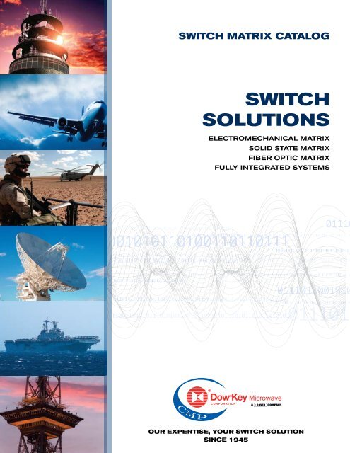
Fiber Optic7001 | C-band Crossbar/Fan-Out7002 | C-band Crossbar/Fan-OutFiber OpticFeaturesInput/Output ConfigurationsOperating FrequencyManual ControlRemote Control16x16 Matrixutilized as 8x14 Crossbarwithtwo 1x4 Fan-Out Segments1530-1565 nm (C-band)LCD Touch ScreenEthernetFeaturesInput/Output ConfigurationsOperating FrequencyManual ControlRemote Control16x16 Matrixutilized as 14x15 crossbarwitha 1x2 Fan-Out Segment1530-1560 nm (C-band)LCD Touch ScreenEthernet7001ApplicationThe 7001 models is a non-blocking 16x16 matrixwith MEMS optical switches and splitters and it isconfigured as a 8x14 crossbar with two 1x4 fan-outswitch segments. It switches input-to-output paths inpure optical domain with a operating wavelength of1530-1565 nm in C-band.The crossbar segment routes any input signal to anyoutput port such that the path between the I/O portsis unique at any given time. Whereas the fan-outconfiguration re-routes outputs 15 &16 back to inputs9-to-12 & 13-to-16 respectively to make two 1x4 fanoutsegments. See appendix C for more details.This model is equipped with a MS Windows basedPC, removable SATA hard drive and redundant powersupplies with LED monitoring and guarded powerswitch on the front panel. Locally it can be controlledthrough an LCD touch screen with Graphical UserInterface (GUI) and remotely through Ethernet.SpecificationsPart Number7001RF CharacteristicsCrossbarSegmentFan-OutSegmentInsertion Loss (1) (max) 2 dB 1.60 dBCrosstalk (max) -70 dB -70 dBBack Reflection (max) -50 dB -50 dBApplicationThe 7002 models is a non-blocking 16x16 matrix withMEMS optical switches and splitters and it is configuredas a 14x15 crossbar with a 1x2 fan-out switch segment.It switches input-to-output paths in pure optical domainwith a operating wavelength of 1530-1565 nm inC-band.RF CharacteristicsTDL (2) (max)WDL (3) (max)0.30 dB0.25 dB0.30 dB0.25 dBThe crossbar segment routes any input signal to anyoutput port such that the path between the I/O ports isTDL (2) (max)PDL (3) (max)0.40 dB0.20 dB0.55 dB0.30 dBPDL (4) (max) 0.05 dB 0.05 dBunique at any given time. Whereas the fan-out segment Repeatability (max) ± 0.04 dB ± 0.04 dBamplifies output 16 and re-routes it to input 15 & 16Repeatability (max) ± 0.02 dB ± 0.02 dBOptical Power (max) 500 mW 500 mWto configure a 1x2 fan-out switch. See appendix C forStability (max) ± 0.02 dB ± 0.02 dBmore details.(1) Measured at 1550 nm(3)(1) This model is equipped with a MS Windows based Polarization Dependent LossMeasured at 1550 nm(2) Time Dependent LossPC, removable SATA hard drive and redundant power(3) Wavelength Dependent Loss specified in ± 20nm rangesupplies with LED monitoring and guarded power(4) Polarization Dependent Lossswitch on the front panel. Locally it can be controlledOptical Power (max) 500 mW 500 mW(2) Time Dependent LossSEE APPENDIX C FOR <strong>SWITCH</strong> SCHEMATICthrough an LCD touch screen with Graphical UserInterface (GUI) and remotely through Ethernet.SEE APPENDIX C FOR <strong>SWITCH</strong> SCHEMATICSpecifications7002Part Number7002CrossbarSegmentFan-OutSegmentInsertion Loss (1) (max) 2 dB 5.4 dBCrosstalk (max) -70 dB -70 dBBack Reflection (max) -47 dB -47 dBRelay Type Non-Latching MEMS Local Control 6.5” (640x480) LCD Touch Screen GUII/O Connector Type LC USB port for keyboard or mouseSwitching Time (max) 35 ms (excl. software delay) Remote Control Ethernet (TCP/IP)Fiber Type 9/125 mm single mode Fault & Error Reporting via Ethernet and LCD (visual)Lifetime (min) 10 9 cycles Commands/Syntax Dow-Key SCPI commandsDimensions (max) 19” wide full rack Operating System Microsoft Windows20” Depth Hard drive (min) 120 GB SATA HD / removable3U Height (5.25”) Power Supply 120-240 VAC, 50-60 Hz, 250 W (max)Operating Temperature 0 °C to +50 °C Power ON/OFF switch with guard on theStorage Temperature -20 °C to +65 °C front and LED indicators for redundancyOperating Humidity 10-80% non-condensing Fuse Accessible/replaceable on the rearWeight (typ) 30 lbs Cooling / Venting 2 fans / side-to-sideRelay Type Non-Latching MEMS Local Control 6.5” (640x480) LCD Touch Screen GUII/O Connector Type FC/APC USB port for keyboard or mouseSwitching Time (max) 35 ms (excl. software delay) Remote Control Ethernet (TCP/IP)Filter Type 9 mm single mode Fault & Error Reporting via Ethernet and LCD (visual)Lifetime (min) 10 9 cycles Commands/Syntax Dow-Key SCPI commandsDimensions (max) 19” wide full rack Operating System Microsoft Windows20” Depth Hard drive (min) 120 GB SATA HD / removable3U Height (5.25”) Power Supply 120-240 VAC, 50-60 Hz, 250 W (max)Operating Temperature 0 °C to +50 °C Power ON/OFF switch with guard on theStorage Temperature -20 °C to +65 °C front and LED indicators for redundancyOperating Humidity 10-80% non-condensing Fuse Accessible/replaceable on the rearWeight (typ) 30 lbs Cooling / Venting 2 fans / side-to-side3-2Dow-Key <strong>Microwave</strong> • www.dowkey.com • 800.266.3695AS9100/ISO-9001: 2008 CertifiedAS9100/ISO-9001: 2008 Certified Dow-Key <strong>Microwave</strong> • www.dowkey.com • 800.266.36953-3
INTEGRATED<strong>SWITCH</strong> SYSTEMCAPABILITIES
Integrated Systems5096 | C-band Fan-Out5190/5191 | L-band Fan-In/Fan-OutIntegrated SystemsApplication RF Characteristics (5096 & 5263)The C-band non-blocking fan-out solid state switchmodel is ideal for SATCOM applications with anarrow band operating frequency of 3.4-4.2 GHz.It can be configured to maximum 16 inputs and 64outputs and is a fully integrated 19” rack 34U modularsystem using (8) sub-modules (32x64):1x Controller module(3U)2x 16x64 Input modules (3U ea.)4x 32x16 Output modules (6U ea.)1x Fan Control module (1U)The system is fully controlled through the Controllermodule, which is equipped with a MS Windowsbased PC, removable SATA hard drive and multiplepower supplies. Locally it can be controlled via anLCD touch screen and remotely with RS-422.On the rear panel, the Input and the Output Modulesare interconnected using 9-pin CAN bus D-subconnectors to create a full 16x64 or 32x64 matrix.Specifications5096VSWR (max)FeaturesInput/Output portsConfigurationOperating FrequencyManual ControlRemote ControlImpedance16x32 expandable to 32x64unidirectionalNon-blocking Full Fan-Out3.4-4.2 GHz (C-band)LCD Touch ScreenRS-42250-OhmPart Numbers5096 (32x64) 5263 (16x64)1.3:1 input & outputIsolation (min)60 dB input/input60 dB input/output60 dB output/output (different input)20 dB output/output (common input)Gain, any path -14 dB ± 2 dB @ 3.8 GHz, 20°CGain, bal. btw. ch. (max) ± 1.5 dB @ 3.8 GHz, 20°CGain Stability ± 0.2 dB over ± 5°CGain, variation vs. freq. ± 0.5 dB over any 40 MHz segment± 0.5 dB over any 80 MHz segment± 1.5 dB over 3.4-4.2 GHz segment1dB Compression (min) -5 dBm output3rd Order Intercept (min) +4 dBm outputNoise Figure (max) 17 dBSpurious Outputs (max) -100 dBm signal dependent-70 dBc signal related5190ApplicationThe L-band non-blocking fan-out transmitter andfan-in receiver model is ideal for Teleport SATCOMapplications with a narrow band operating frequency of950-2050 MHz. The transmitter 19”rack is configuredwith 12 inputs and 48 outputs and the second 19” rackis the receiver tower with 48 inputs and 12 outputs.Each rack is integrated using modular approachconsisting for the following sub-modules:5190/5191: Both Receiver and TransmitterPower supply module, Signal monitor panel and Fiberoptic receiver5190: Receiver Only (48x12)4x 12x12 fan-in module, Main controller and L-Bandamplifiers5191: Transmitter Only (12x48)4x 12x12 fan-out module and Slave controllerSpecifications5191FeaturesInput/Output portsConfigurationOperating FrequencyManual ControlRemote ControlImpedance12x48 Transmitter &48x12 Receiver12x48 Non-blocking Full Fan-Out48x12 Non-blocking Full Fan-In950-2050 MHz (L-band)LCD Touch ScreenRS-42250-OhmPart Numbers5190 (Receiver) 5191 (Transmitter)RF Characteristics (5190 & 5191)VSWR (max)Isolation (min)Gain, any pathPower, Operating (max)Power, no damage (max)1dB Compression (min)3rd Order Intercept (min)Noise Figure (max)1.8:1 input & output55 dB input/input60 dB input/output55 dB output/output (different input)40 dB output/output (common input)0 dB ± 2.5 dB+12 dBm routed to 1output (fan-in)+15 dBm routed to 1output (fan-in)+10 dBm output+21 dBm output17 dB (12x48)21 dB (48x12)Relay Type Solid State Local Control 6.5” LCD Touch ScreenOther Components Amplifiers, Power Dividers USB port for keyboard or mouseI/O Connector Type SMA female Remote Control RS-422 with DB9 maleDimensions (max) 19” wide full rack Commands/Syntax Dow-Key SCPI commands21” Depth Operating System Microsoft Windows34U Height (59.5”) Hard drive 160 GB (min) SATA HD / removableOperating Temperature 0 °C to +50 °C CPU/ Memory Embedded Intel processor / 2G RAM (min)Storage Temperature -40 °C to +50 °C Power Supply 120-240 VAC, 50-60 Hz,1200 W (max)Operating Humidity 10-80% non-condensing (multiple power supplies are included)Weight (typ) 295 lbs (32x64) Fuse Accessible/replaceable on the rearCooling / Venting 1x 1U Fan ModuleRelay Type Solid State Local Control 6.5” LCD Touch ScreenOther Components Amplifiers, Power Dividers &USB port for keyboard or mousePower CombinersRemote Control RS-422 with DB9 maleI/O Connector Type SMA female Commands/Syntax Dow-Key SCPI commandsDimensions (max) 19” wide full rack Operating System Microsoft Windows21” Depth Hard drive 160 GB (min) SATA HD / removableHeight: 16U fan-in /16U fan-out CPU/ Memory Embedded Intel processor / 2G RAM (min)segments plus more modules Power Supply 120-240 VAC, 50-60 Hz, 3-6 A, 350 W / 12VOperating Temperature 0 °C to +50 °C & 50 W / 5 V, redundant power suppliesStorage Temperature -40 °C to +50 °C Fuse Accessible/replaceable on the rearOperating Humidity 10-80% non-condensing Cooling / Venting As needed within each module4-2Dow-Key <strong>Microwave</strong> • www.dowkey.com • 800.266.3695AS9100/ISO-9001: 2008 CertifiedAS9100/ISO-9001: 2008 Certified Dow-Key <strong>Microwave</strong> • www.dowkey.com • 800.266.36954-3
Integrated Systems5230 | L-band Fan-In/Fan-OutFeaturesInput/Output ConfigurationOperating FrequencyManual ControlRemote ControlImpedance4x48 Non-Blocking Full Fan-Out48x4 Non-Blocking Full Fan-In8x2 Electromechanical Matrix (1)950-2050 MHz (L-band)LCD Touch Screen2x Ethernet ports, SNMP50-OhmAPPENDIXRF DATA & SCHEMATICS5230Part Number5230(1) not discussed on this data sheetApplication RF Characteristics (4x48 & 48x4)The L-band non-blocking fan-out/fan-in solid stateswitch model is a compact 4x48 and 48x4 switchmatrix solution integrated with a modular approachusing (7) sub-modules:3x 16x4 Fan-in modules (1U ea.)1x Controller module(3U)3x 4x16 Fan-out modules (1U ea.)The system is fully controlled through the Controllermodule, which is equipped with a MS Windowsbased PC and two removable and replaceable powersupplies cartridges. Locally it can be controlled froman LCD touch screen and remotely via Ethernet withSNMP v1 protocol.On the rear panel, the fan-in and the fan-out modulesare interconnected using RJ11 CAN bus connectorsto create a full 4x48 and 48x4 matrix. (The 8x2 switchresides inside the control module)SpecificationsVSWR (max)Isolation (min)fan-in onlyfan-out onlyGainPower, Operating (max)1dB Compression (min)3rd Order Intercept (min)Noise Figure (max)1.8:1 input & output60 dB input/input60 dB input/output60 dB output/output (different input)60 dB output/output (common input)40 dB output/output (common input)+2 dB ± 2 dB+3 dBm routed to 1 output (fan-in)+14 dBm routed to 1 output (fan-out)1 dBm (fan-in)8 dBm (fan-out)+17 dBm (fan-in), -9 dBm input power+24 dBm (fan-out), +6 dBm input power20 dB (fan-in)18 dB (fan-out)Relay Type Solid State Local Control 6.5” LCD Touch Screen GUIOther Components Amplifiers, Power Dividers &USB port for keyboard or mousePower CombinersRemote Control Ethernet with SNMP v1 protocolI/O Connector Type SMA female 2x RJ-45 connectors availableDimensions (max) 19” Wide Operating System Microsoft Windows21” Depth Hard drive 160 GB (min) SATA HD / removable9U Height (15.75”) CPU/ Memory Embedded Intel processor / 2G RAM (min)Operating Temperature 0 °C to +40 °C Power Supply 120-240 VAC, 50-60 Hz, 2x 300 W (max)Storage Temperature -40 °C to +40 °C 2x power module cartridges, Power ON/OFFOperating Humidity 10-80% non-condensing switch with guard on the front panelFuseAccessible/replaceable on the rear4-4Dow-Key <strong>Microwave</strong> • www.dowkey.com • 800.266.3695AS9100/ISO-9001: 2008 CertifiedAS9100/ISO-9001: 2000 Certified Dow-Key <strong>Microwave</strong> • www.dowkey.com • 800.266.3695 ii
Appendix ADetermine Enclosure HeightMP-Series RF DataAppendix BThe Tables are to guide on how to determine the enclosure height for the MS-Series.Depending on switch type, number of input & output ports and connector type, the number of switches that canbe mounted on the rear panel or inside an enclosure varies.SMA, NON-TERMINATED (NT), TERMINATED (T), MOUNTED ON THE REAR PANEL, 1-8 <strong>SWITCH</strong>ESSPDT (1) /DPDT SP3T SP4T SP6T SP8T SP10T SP12T1RU 5NT, 5T (1) 5NT 5NT 5NT - - -2RU 4NT, 4T (1) 4NT, 4T 4NT, 4T 4NT, 4T 4NT, 4T 4NT 4NT,4T3RU 4NT, 4T (1) - - - - - -4RU 8NT, 8T (1) 8NT, 8T 8NT, 8T 8NT, 8T 8NT, 8T 8NT 8NT, 8T(1)For SPDT one port on the DPDT switch is externally terminated to 2W 50-ohm load.SMA, NON-TERMINATED (NT), TERMINATED (T), MOUNTED INSIDE THE MATRIX, 9-35 <strong>SWITCH</strong>ESDPDT SP3T SP4T SP6T SP8T SP10T SP12T1RU - - - - - - -2RU 15NT 15NT, 15T 14NT, 14T 10NT, 10T - - -3RU 18NT 27NT, 27T 21NT, 21T 15NT, 15T 12NT,12T 9NT -4RU 24NT 35NT, 35T 28NT, 28T 20NT, 20T 16NT,16T 13NT 11NT, 11TN, NON-TERMINATED (NT), TERMINATED (T), MOUNTED INSIDE THE MATRIX, 2-16 <strong>SWITCH</strong>ESDPDT SP3T SP4T SP6T SP8T SP10T SP12T1RU - - - - - - -2RU 8NT - - 3NT 2NT,2T 2NT -3RU 12NT - - 5NT, 5T 4NT, 4T 3NT 2NT, 2T4RU 16NT - - 6NT, 6T 5NT, 5T 4NT 3NT, 3TFor TNC and BNC connectors contact Dow-Key.DC-18 GHZ TERMINATED <strong>SWITCH</strong>ES WITH SMA-TYPE CONNECTORSTHE RF PERFORMANCEFOR ≤1x56IS SLIGHTLYFrequencyBETTER.[GHz]DC-18 GHz, Terminated, SMAVSWRMax.IsolationMin. [dB]Insertion LossMax. [dB]1x13 to 1x85CW PowerMax. [W]DC-4 1.4 80 1.0 904-8 1.8 80 1.5 608-12 2.0 80 2.0 4512-18 2.6 80 3.0 35DC-18 GHz, Terminated, SMAFrequency[GHz]VARIOUS <strong>SWITCH</strong> COMBINATIONS MOUNTED ON THE REARSP10 & SP12T <strong>SWITCH</strong>ES MOUNTED INSIDE THE ENCLOSUREVSWRMax.IsolationMin. [dB]Insertion LossMax. [dB]1x86 to 1x132CW PowerMax. [W]DC-4 1.4 80 3.0 904-8 1.8 80 4.5 608-12 2.0 80 5.5 4512-18 2.6 80 7.5 35DC-18 GHZ <strong>SWITCH</strong>ES WITH N-TYPE CONNECTORSDC-18 GHz, Non-Terminated, NFrequency[GHz]VSWRMax.IsolationMin. [dB]Insertion LossMax. [dB]1x13 to 1x47CW PowerMax. [W]DC-4 1.4 80 2.0 904-8 1.6 80 3.0 608-12 1.8 80 4.0 4512-18 2.2 80 5.5 35DC-18 GHz, Terminated, NFrequency[GHz]SP10T MOUNTED INSIDE THE ENCLOSURESP8T & SP10T <strong>SWITCH</strong>ES MOUNTED INSIDE THE ENCLOSUREVSWRMax.IsolationMin. [dB]Insertion LossMax. [dB]1x13 to 1x47CW PowerMax. [W]DC-4 1.4 80 2.5 904-8 1.6 80 4.0 608-12 1.8 80 5.0 4512-18 2.1 80 6.5 35We reserve the right to alter, amend or replace any specifications at our sole discretion and without prior notice.We reserve the right to alter, amend or replace any specifications at our sole discretion and without prior notice.5-2Dow-Key <strong>Microwave</strong> • www.dowkey.com • 800.266.3695AS9100/ISO-9001: 2008 CertifiedAS9100/ISO-9001: 2008 Certified Dow-Key <strong>Microwave</strong> • www.dowkey.com • 800.266.36955-3
Appendix CSwitch SchematicsSwitch SchematicsAppendix CMS-SERIES: Exmaple of Individual SwitchesCB-SERIES: Example of Crossbar Switch Configurations4x SP4T NON-TERMINATED <strong>SWITCH</strong>1x DPDT <strong>SWITCH</strong>4x SP8T TERMINATED <strong>SWITCH</strong>6X8 NON-TERMINATED <strong>SWITCH</strong>MP-SERIES: Example of 1xN Switch Configurations1x16 NON-TERMINATED <strong>SWITCH</strong>1x100 NON-TERMINATED <strong>SWITCH</strong>4X4 NON-TERMINATED <strong>SWITCH</strong>1x20 NON-TERMINATED <strong>SWITCH</strong>MOUNTED ON THE REAR(OUTSIDE THE ENCLOSURE)We reserve the right to alter, amend or replace any specifications at our sole discretion and without prior notice.We reserve the right to alter, amend or replace any specifications at our sole discretion and without prior notice.5-4Dow-Key <strong>Microwave</strong> • www.dowkey.com • 800.266.3695AS9100/ISO-9001: 2008 CertifiedAS9100/ISO-9001: 2008 Certified Dow-Key <strong>Microwave</strong> • www.dowkey.com • 800.266.36955-5
Appendix CSwitch SchematicsMODEL MP-SERIES: 4141: <strong>SWITCH</strong>ES 2X32 Switch CASCADED Configuration 2-LEVELSCERAMIC & MICROWAVE PRODUCTSElectronic Components & <strong>Microwave</strong> SolutionsCeramic & <strong>Microwave</strong> Products (CMP) designs, manufactures andsells special electronic components and systems, including highperformancefilters, switches, capacitors and EMI and cosite signalinterference solutions. Our products are used in military, space,telecom infrastructure, medical and industrial applications wherefunction and reliability are crucial.www.dovercmp.comDow-Key <strong>Microwave</strong>4822 McGrath Street, Ventura, CA 93003 USATel +1.805.650.0260Fax +1.805.650.1734Email askdk@dowkey.comDielectric Laboratories, Inc.2777 Route 20 East, Cazenovia, NY 13035 USATel +1.315.655.8710Fax +1.315.655.0445Email sales@dilabs.comBSC Filters Ltd.Jorvik House , Outgang Lane, York, YO19 5UP, EnglandTel +44.1904.438438Fax +44.1904.438123Email sales@bscfilters.com7001 Switch Configuration 7002 Switch ConfigurationK&L <strong>Microwave</strong>2250 Northwood Drive, Salisbury, MD 21801 USATel +1.410.749.2424Fax +1.443.260.2268Email sales@klmicrowave.comNovacap25111 Anza Drive, Valencia, CA 91355 USATel +1.661.295.5920Fax +1.661.295.5928Email info@novacap.comPole/Zero Corporation5558 Union Centre Drive, West Chester, OH 45069 USATel +1.513.870.9060Fax +1.513.870.9064Email support@polezero.comSyfer Technology Ltd.Old Stoke Road, Arminghall, Norwich, NR14 8SQ UKTel +44.1603.723300Fax +44.1603.723301Email sales@syfer.co.ukWe reserve the right to alter, amend or replace any specifications at our sole discretion and without prior notice.Voltronics Corporation100-10 Ford Road, Denville, NJ 07834 USATel +1.973.586.8585Fax +1.973.586.3404Email info@voltronicscorp.com5-6Dow-Key <strong>Microwave</strong> • www.dowkey.com • 800.266.3695AS9100/ISO-9001: 2008 Certified
4822 McGrath Street | Ventura, CA 93003-5641Tel 805.650.0260 | Fax 805.650.1734 | www.dowkey.com