ADL 2391 Revision Questions 2 1003.pdf
ADL 2391 Revision Questions 2 1003.pdf
ADL 2391 Revision Questions 2 1003.pdf

You also want an ePaper? Increase the reach of your titles
YUMPU automatically turns print PDFs into web optimized ePapers that Google loves.
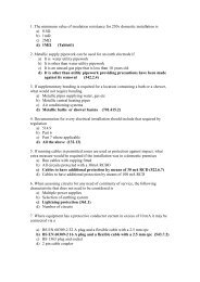
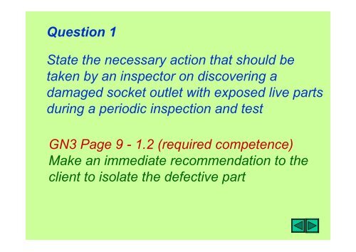
Question 1<br />
State the necessary action that should be<br />
taken by an inspector on discovering a<br />
damaged socket outlet with exposed live parts<br />
during a periodic inspection and test<br />
GN3 Page 9 - 1.2 (required competence)<br />
Make an immediate recommendation to the<br />
client to isolate the defective part
Question 2<br />
State the documentation that should<br />
accompany an Installation Certificate or<br />
Periodic Inspection Report<br />
GN3 Page 9 1.3.1 (Certificates and Reports)<br />
1. Schedule of items inspected<br />
2. Schedule of test results
Question 3<br />
Why is it necessary to undertake an initial<br />
verification<br />
GN3 Page 11 - 2.1 (Initial Verification)<br />
1. Confirm that installation complies with<br />
designers intentions<br />
2. Constructed, inspected and tested to<br />
BS 7671
Question 4<br />
State the requirements of Chapter 71 of<br />
BS 7671 with regard to initial verification<br />
GN3 Page 11 - 2.1 (Initial Verification)<br />
1. All fixed equipment and material complies<br />
with applicable British Standards or<br />
acceptable equivalents<br />
2. All parts of the fixed installation are correctly<br />
selected and erected<br />
3. Not visibly damaged or defective
Question 5<br />
Identify FIVE non-statutory documents that a<br />
person undertaking an inspection and test<br />
need to refer to<br />
General Knowledge<br />
1. BS 7671<br />
2. IEE On-Site Guide<br />
3. GS 38<br />
4. Guidance Note 3<br />
5. Memorandum of Guidance to The Electricity<br />
at Work Regulations
Question 6<br />
Which non-statutory document recommends<br />
records of all maintenance including test<br />
results be kept throughout the life of an<br />
installation<br />
GN3 Page 11 - 2.1 (Initial Verification)<br />
Memorandum of Guidance to The Electricity<br />
at Work Regulations (Regulation 4(2)
Question 7<br />
Appendix 6 of BS 7671 allows the use of three<br />
forms for the initial certification of a new<br />
installation or for an alteration or an addition<br />
to an existing installation. State the title given<br />
each of these certificates<br />
GN3 Page 12 - 2.1 (Initial Verification)<br />
1. Multiple signature Electrical Installation Cert.<br />
2. Single signature Electrical Installation Cert<br />
3. Minor Electrical Installation Works Certificate
Question 8<br />
Under what circumstances would it be<br />
appropriate to issue a single signature<br />
Electrical Installation Certificate<br />
GN3 Page 12 - 2.2 (Certificates)<br />
Where design, construction inspection and<br />
testing is the responsibility of one person
Question 9<br />
State the information that should be made<br />
available to the inspector<br />
GN3 Page 13 - 2.3 (Required information)<br />
1. Maximum demand<br />
2. Number and type of live conductors at the<br />
origin<br />
3. Type of earthing arrangements<br />
4. Nominal voltage and supply frequency<br />
5. Prospective fault current (PFC)<br />
6. External Impedance Ze<br />
7. Type and rating of overcurrent device at<br />
the origin
Question 9 (cont’d)<br />
The following information should also be made<br />
available<br />
GN3 Page 13 - 2.3 (Required information)<br />
1 Type and composition of circuits, including<br />
points of utilisation, number and size of<br />
conductors and type of cable<br />
2. Methods of compliance for indirect shock protection<br />
3. Identification and location of devices used for<br />
protection, isolation and switching<br />
4. Circuits or equipment vulnerable to testing
Question 10<br />
Where should the proposed interval between<br />
periodic inspections should be noted<br />
GN3 Page 14 - 2.5 (Frequency)<br />
1. On the Electrical Installation Certificate<br />
2. On a notice fixed in a prominent position<br />
at or near the origin of an installation
Question 11<br />
State FIVE methods of protection against<br />
indirect shock<br />
GN3 Page 16 (Protection against indirect<br />
contact)<br />
1. EEBADOS<br />
2. Class II<br />
3. Non-conducting location<br />
4. Earth-free local equipotential bonding<br />
5. Electrical separation
Question 12<br />
State in the correct sequence the first FIVE<br />
tests that would need to be undertaken on an<br />
A1 ring circuit during an initial verification<br />
GN3 Page 29 2.7.4<br />
1. Continuity of protective conductors<br />
2. Continuity of ring final circuit conductors<br />
3. Insulation resistance<br />
4. Polarity<br />
5. Impedance Zs
Question 12<br />
State TWO disadvantages of using Method 2<br />
in order to verify the continuity of c.p.c.’s<br />
GN3 Page 32 Fig. 1b (Test method 2)<br />
1. Long wander lead<br />
2. Gives R 2 value only (does not provide R 1 )
Question 14<br />
State the British Standard number for a<br />
transformer used to provide electrical<br />
separation<br />
GN3 Page 18v (Electrical separation)<br />
Transformer complies with BS 3535<br />
Note: Transformer double-wound type
Question 15<br />
List FOUR types of external influence that<br />
affect the safety/operation of an electrical<br />
installation<br />
GN3 Page 19xiv (Electrical separation)<br />
1. Ambient temperature<br />
2. Heat<br />
3. Water<br />
4. Corrosion
Question 16<br />
Identify the TWO procedures required when<br />
verifying the continuity of a ferrous enclosure<br />
used as a c.p.c. for a circuit<br />
GN3 Page 33 (Test method 2)<br />
1. Inspect the enclosure throughout its length<br />
2. Carry out low resistance ohmmeter test
Question 17<br />
State in the correct sequence the tests<br />
required to verify the continuity of a ring final<br />
circuit<br />
GN3 Page 33 (Continuity of ring final circuit)<br />
1. Identify and measure the resistance of each<br />
ring (end to end) r1 r2 rn<br />
2. Apply figure of 8 (cross connection) between<br />
phase and neutral conductors at distribution<br />
board and then measure resistance between<br />
phase/neutral at each socket outlet
Question 17 cont’d<br />
GN3 Page 33 (Continuity of ring final circuit)<br />
3. Apply figure of 8 (cross connection)<br />
between phase and cpc at origin and<br />
measure resistance between phase and<br />
cpc at each socket outlet<br />
Note: where dead tests are made the supply<br />
must be isolated before any work commences
Question 18<br />
The following measurements were taken at<br />
the origin of an A 1 ring circuit.<br />
r1 = 0.4 r2 = 0.67 rn = 0.4<br />
Determine the measured value of resistance<br />
at each socket outlet when the ends of the<br />
circuit are cross-connected to form a figure 8<br />
GN3 Page 34 (Continuity of ring final circuit)<br />
1. r1 + rn = 0.4 + 0.4 = 0.8/4 = 0.2<br />
2. r1 + r2 = 0.4 + 0.67 = 1.07/4 = 0.267
Question 19<br />
Identify ONE other test that is automatically<br />
performed when undertaking a ring final circuit<br />
test<br />
GN3 Page 34 (Continuity of ring final circuit)<br />
Polarity
Question 20<br />
State FOUR items of equipment/components<br />
that may need to be removed prior to carrying<br />
out a test for insulation resistance on a circuit<br />
GN3 Page 35 (Insulation resistance)<br />
1. Pilot or indicator lamps<br />
2. Dimmer switches<br />
3. Touch switches<br />
4. Electronic r.c.d.’s etc
Question 21<br />
State the test voltage and minimum acceptable<br />
value of insulation resistance for the following<br />
circuits<br />
1. 400V 3 phase motor<br />
2. 760V discharge lighting circuit<br />
3. 45V FELV circuit<br />
GN3 Page 36 (Table 2.2)<br />
1. 500V d.c. 0.5 M<br />
2. 1000V d.c. 1.0 M<br />
3. 500V d.c. 0.5 M
Question 22<br />
State the correct sequence for undertaking an<br />
insulation resistance test on a filament lamp<br />
circuit containing two-way switching<br />
GN3 Page 36 (Insulation resistance testing)<br />
1. Supply must be isolated<br />
2. All lamps removed<br />
3. Insulation test between live conductor<br />
4. Insulation resistance test between live conductors<br />
and c.p.c.<br />
5. Two-way switches operated during test
Question 23<br />
State the type of test that should be applied<br />
where protection against direct contact is by<br />
site-applied insulation<br />
GN3 Page 40 (Site applied insulation)<br />
1. Test at 3750V a.c.<br />
2. Apply test voltage for 60 seconds during<br />
which time insulation failure or flashover<br />
should not occur<br />
3. Instrument used: Site applied insulation<br />
tester
Question 24<br />
State the THREE specific requirements for<br />
verification of polarity with regard to<br />
accessories<br />
GN3 Page 48 2.7.12 (Polarity)<br />
1. All single-pole devices are connected in<br />
the phase conductor<br />
2. The centre contact of Edison screw lamps<br />
are connected in the phase conductor<br />
3. All socket outlets
Question 25<br />
Identify the test that should be applied to<br />
verify polarity after the supply is energised<br />
GN3 Page 48 2.7.12 (Polarity)<br />
Test to verify correct polarity of the incoming<br />
live supply (PES). Test made at the origin<br />
using approved voltage indicator
Question 26<br />
Identify the THREE electrodes used when<br />
used with a proprietary earth resistance<br />
tester<br />
GN3 Page 50 2.7.13 (Earth electrode resistance)<br />
1. Main electrode<br />
2. Potential electrode (auxiliary electrode)<br />
3. Current electrode (auxiliary electrode)<br />
Note: This method can be use for electrodes<br />
used for transformers, lightning<br />
protection systems etc.
Question 27<br />
State the action to be taken regarding the<br />
earthing conductor before measuring the<br />
resistance of an earth electrode<br />
GN3 Page 52 2.7.13 (Earth electrode testing)<br />
1. Disconnect earthing conductor at MET<br />
to avoid parallel earth paths<br />
2. Do NOT disconnect any protective<br />
conductors before isolating the supply
Question 27<br />
State the maximum value of permitted earth<br />
electrode resistance for a TT system when<br />
protection is afforded by a 500mA r.c.d.<br />
GN3 Page 50 2.3 (Earth electrode for RCD’s)<br />
Table 2.3 Normal 100 Special locations 50<br />
By calculation 50V/0.5A = 100 Dry<br />
25V/0.5A = 50 Special Loc
Question 28<br />
State the maximum recommended value of<br />
resistance for an earth electrode<br />
GN3 Page 53 2.3 (Earth electrode for RCD’s)<br />
Electrodes having resistances in excess of<br />
200 will require further investigation.<br />
Note: Electrode resistances obtained in excess<br />
of 200 may indicate unstable soil conditions
Question 29<br />
State the formula used to calculate Impedance<br />
Zs, at the furthest point within a circuit<br />
GN3 Page 53 2.7.14 (Earth fault loop)<br />
Zs = Ze + (R 1 +R 2 )<br />
Where Ze is by measurement or enquiry<br />
and (R 1 +R 2 ) by measurement
Question 30<br />
State TWO reasons why it is necessary to<br />
measure external earth fault loop impedance<br />
at the origin of an installation<br />
GN3 Page 53 2.7.14 (Determining Ze)<br />
1. To verify an earth connection<br />
2. The value is equal to or less than the value<br />
determined by the designer
Question 31<br />
State THREE methods by which the<br />
impedance of a circuit may be obtained<br />
without operating any r.c.d.’s protecting the<br />
circuit<br />
GN3 Page 56 (Residual current devices)<br />
1. D-Lok<br />
2. Soft test (15mA)<br />
3. By calculation Zs = Ze + (R 1 +R 2 )
Question 32<br />
Determine the prospective fault current given<br />
following information (Three phase supply<br />
1. Impedance between P and N = 0.25 <br />
2. Impedance between P and E = 0.5 <br />
(General knowledge)<br />
1. 240V(uoc)/0.25 = 960A = 0.96kA<br />
2. 240/0.5 = 480A = 0.48kA<br />
3. For three phase multiply P to N value by 2<br />
0.96 x 2 = 1.92kA
Question 33<br />
State the reason for undertaking a prospective<br />
fault current measurement at the distribution<br />
board at the origin of the installation<br />
Page 57 2.7.15 (Prospective fault current)<br />
1. To ensure the adequate breaking capacity<br />
of the overcurrent devices<br />
2. To ensure the adequate breaking capacity<br />
of the main switch
Question 34<br />
State the three required electrical tests<br />
required to be undertaken on a 30mA r.c.d.<br />
complying with BS 4293<br />
Page 62 2.7.16 (Functional testing)<br />
1. 1/2 test - 15mA for 2 seconds - device does<br />
not trip<br />
2. 1 x test - device tested at full rated current<br />
trips within 200mS (0.2 seconds)<br />
3. 5 x test when tested at 150mS device<br />
operates within 40mS
Question 35<br />
State FIVE items of electrical equipment that<br />
would require functional testing<br />
Page 63 2.7.16 (Functional checks)<br />
1. R.c.d.’s<br />
www.djtelectraining.co.uk<br />
2. Circuit breakers<br />
3. Isolators<br />
4. Interlocks<br />
5. Switches