Plasma Wall Interactions in ITER and Implications for Fusion Reactors
Plasma Wall Interactions in ITER and Implications for Fusion Reactors
Plasma Wall Interactions in ITER and Implications for Fusion Reactors

You also want an ePaper? Increase the reach of your titles
YUMPU automatically turns print PDFs into web optimized ePapers that Google loves.
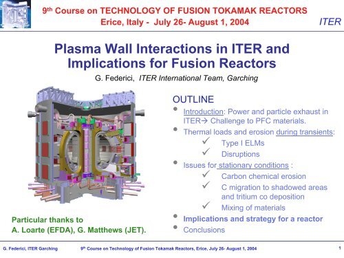
9 th Course on TECHNOLOGY OF FUSION TOKAMAK REACTORS<br />
Erice, Italy - July 26- August 1, 2004<br />
<strong>ITER</strong><br />
<strong>Plasma</strong> <strong>Wall</strong> <strong>Interactions</strong> <strong>in</strong> <strong>ITER</strong> <strong>and</strong><br />
<strong>Implications</strong> <strong>for</strong> <strong>Fusion</strong> <strong>Reactors</strong><br />
G. Federici, <strong>ITER</strong> International Team, Garch<strong>in</strong>g<br />
Particular thanks to<br />
A. Loarte (EFDA), G. Matthews (JET).<br />
OUTLINE<br />
• Introduction: Power <strong>and</strong> particle exhaust <strong>in</strong><br />
<strong>ITER</strong> Challenge to PFC materials.<br />
• Thermal loads <strong>and</strong> erosion dur<strong>in</strong>g transients:<br />
Type I ELMs<br />
<br />
<br />
Disruptions<br />
• Issues <strong>for</strong> stationary conditions :<br />
Carbon chemical erosion<br />
<br />
<br />
<br />
C migration to shadowed areas<br />
<strong>and</strong> tritium co deposition<br />
Mix<strong>in</strong>g of materials<br />
• <strong>Implications</strong> <strong>and</strong> strategy <strong>for</strong> a reactor<br />
• Conclusions<br />
G. Federici, <strong>ITER</strong> Garch<strong>in</strong>g 9 th Course on Technology of <strong>Fusion</strong> Tokamak <strong>Reactors</strong>, Erice, July 26- August 1, 2004<br />
1
Introduction (I)<br />
Power <strong>and</strong> Particle Exhaust <strong>in</strong> Next-Step Devices<br />
• Dom<strong>in</strong>ant α Heat<strong>in</strong>g (P α<br />
≥ 2P add<br />
)<br />
Q DT<br />
= P fus<br />
/P add<br />
≥ 10<br />
• “Reasonable <strong>Fusion</strong> Power” ≥ 500 MW<br />
-P α<br />
≥ 100 MW<br />
- Power exhaust ≥ 150 MW<br />
> P SOL ~ 100 MW<br />
> q II ~ 1 GW/m 2<br />
> q ┴<br />
PCF<br />
≤ 10 MW/m 2<br />
a) Low angle of <strong>in</strong>cidence on target ~3°q ┴<br />
PCF<br />
~50 MW/m 2<br />
b) Large SOL radiation Divertor P rad<br />
~0.6 P SOL<br />
<strong>ITER</strong><br />
• He exhaust ≥ 1.8 10 20 He/s<br />
• Tritium throughput :<br />
•M<strong>in</strong>. (η He<br />
~ 0.1) ~ 10 21 s -1<br />
• Max. limit : Reprocess<strong>in</strong>g<br />
<strong>and</strong> Reasonable <strong>in</strong>ventory<br />
(5 10 22 s -1 0.25 g/s)<br />
Basic Ingredient<br />
C chemical Erosion ~ 1%<br />
Γ D ~ 10 25 s -1 Γ C ~ 10 23 s -1<br />
(extr<strong>in</strong>sic Impurities <strong>for</strong> f<strong>in</strong>e-tun<strong>in</strong>g)<br />
B2-EIRENE<br />
A. Kukushk<strong>in</strong><br />
G. Federici, <strong>ITER</strong> Garch<strong>in</strong>g 9 th Course on Technology of <strong>Fusion</strong> Tokamak <strong>Reactors</strong>, Erice, July 26- August 1, 2004<br />
2
Introduction (II)<br />
Disruptions <strong>and</strong> ELMs will be:<br />
- strictly regulated <strong>in</strong> <strong>ITER</strong><br />
- not permitted <strong>in</strong> DEMO<br />
W thermal (MJ) 0.2<br />
G. Matthews, PSI 2004<br />
0.8 10 350 1500<br />
A plasma (m 2 ) 50 200 700 1200<br />
7<br />
<strong>ITER</strong><br />
W thermal /A plasma (MJ/m 2 ) .03 .02 .05 0.5 1.2<br />
Perfect<br />
disruption<br />
mitigation<br />
A divertor (m 2 ) 0.2 0.5 1 3 5<br />
∆W ELM /W th >100% 90% 15% 2%<br />
Introduction (III)<br />
<strong>Implications</strong> on design <strong>and</strong> mach<strong>in</strong>e operation<br />
<strong>ITER</strong><br />
• Thermal transients<br />
(e.g., ELMs <strong>and</strong><br />
disruptions) strongly<br />
affect operation <strong>and</strong><br />
drive material choice.<br />
–Type I ELMs may cause<br />
unacceptable divertor<br />
erosion <strong>and</strong> damage at<br />
the wall, <strong>and</strong> <strong>in</strong> the<br />
case of C contribute to<br />
tritium co-deposition.<br />
–Unmitigated<br />
disruptions lead to W<br />
melt<strong>in</strong>g <strong>and</strong> probably<br />
‘mitigated’ disruptions<br />
could damage the Be<br />
wall (e.g., <strong>for</strong>mation of<br />
melt layer whose<br />
behaviour <strong>and</strong><br />
properties are<br />
uncerta<strong>in</strong>).<br />
Bad News!!!<br />
PMIs <strong>in</strong> <strong>ITER</strong> will scale up orders of<br />
magnitude with <strong>in</strong>crease <strong>in</strong> stored<br />
energy <strong>and</strong> pulse duration<br />
Parameter<br />
Today’s<br />
tokamaks<br />
• In-vessel tritium <strong>in</strong>ventory with<br />
carbon PFCs could rapidly<br />
reach safety limit (>300 g).<br />
– Current estimates ≈ few<br />
hundred pulses <strong>in</strong> <strong>ITER</strong>.<br />
– Poor validation of models to<br />
predict T retention <strong>in</strong> <strong>ITER</strong>.<br />
They are far from expla<strong>in</strong><strong>in</strong>g<br />
experimental results<br />
(underestimates).<br />
• No eng<strong>in</strong>eer<strong>in</strong>g-scale<br />
demonstration of fast<br />
<strong>and</strong> efficient tritium<br />
removal from<br />
tokamaks to date !<br />
• Urgent needs<br />
– PWI diagnostics <strong>and</strong> measurement methods <strong>and</strong> strategies to learn as we operate.<br />
– We take a risk if we do not test/validate proposed material choices <strong>in</strong> exist<strong>in</strong>g tokamaks.<br />
– Push ahead now to develop zero C scenarios (i.e., high-Z).<br />
<strong>ITER</strong><br />
Factor<br />
X times<br />
Ethermα R 5 (MJ) 1-15 350 25-300<br />
Disruptions ( MJ/m 2 ) 0.03-0.5 ~1-10<br />
Type I ELMs (MJ)<br />
(MJ/m 2 )<br />
0.1-0.6<br />
0.01-0.3<br />
8-20<br />
0.1-2<br />
Pulse duration (s) 10-25 400<br />
Cum. Run time (hr/y) 2-8 hr/y >200 hr/y<br />
C-erosion divertor 7-300 µm/yr > 1 cm/yr<br />
T-<strong>in</strong>jected/ pulse (g) 0.2 ~100<br />
2-20<br />
10-30<br />
10-40<br />
25<br />
100<br />
>100<br />
G. Federici, <strong>ITER</strong> Garch<strong>in</strong>g 9 th Course on Technology of <strong>Fusion</strong> Tokamak <strong>Reactors</strong>, Erice, July 26- August 1, 2004<br />
4
Introduction (IV)<br />
PFC materials selection - 3 materials to start with<br />
<strong>ITER</strong><br />
Behaviour under transient <strong>and</strong> steady-state loads<br />
PFC Material Choice <strong>for</strong> <strong>ITER</strong><br />
~ 700m 2 Be first wall : low Z + Oxygen getter<br />
~ 100m 2 W Baffle/Dome : low Erosion, long Lifetime<br />
~ 50 m 2 Graphite CFC Divertor Target ( W):<br />
a) No Melt<strong>in</strong>g under transient Power Loads (ELMs<br />
<strong>and</strong> Disruptions)<br />
b) Compatibility with wide Range of <strong>Plasma</strong><br />
Regimes (T e,div<br />
~ 1 – 100 eV)<br />
c) C is a very good radiator right where it needs to<br />
be (i.e., Te <strong>in</strong> the divertor)<br />
‣ Is this a reasonable choice<br />
‣ What are the implications of this choice<br />
‣ What rema<strong>in</strong>s to be addressed to demonstrate the validity of this choice<br />
‣ What are the feasibility issues <strong>and</strong> operation implications of alternatives<br />
G. Federici, <strong>ITER</strong> Garch<strong>in</strong>g 9 th Course on Technology of <strong>Fusion</strong> Tokamak <strong>Reactors</strong>, Erice, July 26- August 1, 2004<br />
5
Introduction (V)<br />
We plan to use C <strong>in</strong> the divertor dur<strong>in</strong>g <strong>in</strong>itial operation<br />
<strong>ITER</strong><br />
• The rationale <strong>for</strong> us<strong>in</strong>g carbon <strong>in</strong> the <strong>ITER</strong> divertor follows directly from:<br />
– the projected levels of thermal loads <strong>and</strong> damage dur<strong>in</strong>g thermal transients<br />
(e.g., type I ELMs/ disruptions). These are still uncerta<strong>in</strong> <strong>and</strong> need R&D.<br />
• Two strategies <strong>for</strong> the <strong>ITER</strong> divertor:<br />
(1) reta<strong>in</strong> CFC dur<strong>in</strong>g operation with H- <strong>and</strong> D. This implies availability of:<br />
• <strong>in</strong>-situ time- <strong>and</strong> space-resolved, as well as global measurements of D-retention<br />
<strong>and</strong> erosion <strong>and</strong> validated modell<strong>in</strong>g tools, which would enable to monitor status of<br />
D retention <strong>in</strong> <strong>ITER</strong> dur<strong>in</strong>g D-operation <strong>and</strong> predict conditions dur<strong>in</strong>g DT operation.<br />
• efficient methods <strong>for</strong> T-removal, which still need to be developed <strong>and</strong> tested <strong>in</strong><br />
tokamaks with the relevant materials mix <strong>and</strong> temperatures.<br />
(2) start with full-W divertor <strong>and</strong> develop compatible operat<strong>in</strong>g scenarios.<br />
• This means accept<strong>in</strong>g greater restrictions on <strong>ITER</strong> operat<strong>in</strong>g space.<br />
• The issue of operation with an all metal wall (high or low Z) <strong>and</strong> no carbon still<br />
needs to be explored <strong>in</strong> current mach<strong>in</strong>es <strong>and</strong> scaled with mach<strong>in</strong>e size.<br />
• If we are to live without C, we have to f<strong>in</strong>d alternative ways to radiate.<br />
G. Federici, <strong>ITER</strong> Garch<strong>in</strong>g 9 th Course on Technology of <strong>Fusion</strong> Tokamak <strong>Reactors</strong>, Erice, July 26- August 1, 2004<br />
6
Transients (I)<br />
Type I Edge Localised Modes (ELMs)<br />
<strong>ITER</strong><br />
A. Loarte, <strong>Plasma</strong> Phys. Control. <strong>Fusion</strong> 45 (2003) 1548<br />
Next step Experiments @ Q DT<br />
~ 10 require high τ E<br />
<strong>and</strong> n e<br />
Regimes<br />
High (n e<br />
, τ E<br />
) Type I H-mode provides a robust Regime to achieve Q DT<br />
~ 10<br />
H-mode ETB Pedestal<br />
Type I ELM<br />
W JET<br />
~ 2 – 12 MJ vs. W <strong>ITER</strong><br />
~ 350 MJ<br />
A <strong>ITER</strong><br />
/A JET<br />
~ 2 – 3<br />
<strong>ITER</strong> Type I ELM Energy Flux :<br />
<strong>Plasma</strong> Pressure<br />
‣ E ELM<br />
= 0.5 – 5.0 MJ/m 2<br />
‣ Duration Energy Pulse= 0.2 – 1 ms<br />
‣ f ELM<br />
= 1 - 10 Hz<br />
JET - Low Density - Eich PSI 2002<br />
Talk of Janeschitz<br />
Regimes with high (τ E , n e ) & small ELMs exist <strong>in</strong><br />
some devices but have non-negligible drawbacks<br />
(q 95 > 3.5, operation close to DNX, …)<br />
τ<br />
G. Federici, <strong>ITER</strong> Garch<strong>in</strong>g 9 th Course on Technology of <strong>Fusion</strong> Tokamak <strong>Reactors</strong>, Erice, July 26- August 1, 2004<br />
7
Transients (II)<br />
Thermal loads <strong>and</strong> erosion dur<strong>in</strong>g ELMs<br />
<strong>ITER</strong><br />
Ma<strong>in</strong> problems aris<strong>in</strong>g <strong>for</strong> <strong>ITER</strong>:<br />
Divertor target erosion lifetime.<br />
Impurity production <strong>and</strong> plasma contam<strong>in</strong>ation.<br />
*E+03<br />
Heat fluxes (MW/m2) , Temperature (˚C)<br />
0.0 0.5 1.0 1.5 2.0 2.5 3.0 3.5 4.0<br />
Tsurf<br />
qdiv<br />
qcond<br />
5<br />
qevap<br />
1. 2. 3. 4. 5. 6. 7. 8. 9. 10.<br />
Time (s)<br />
2<br />
*E-04<br />
δevap ~ 3-4 µm<br />
0. 1. 2. 3.<br />
Evaporation (µm)<br />
Temperature (˚C) *E+03<br />
1. 2. 3. 4.<br />
100s of ELMs per <strong>ITER</strong> pulse<br />
0. 1. 2. 3. 4. 5. 6. 7. 8. 9. 10.<br />
Time (s)<br />
Because of short duration of ELMs steep temperature<br />
gradients only near-surface ≤ 300 µm<br />
G. Federici, <strong>Plasma</strong> Phys. Control. <strong>Fusion</strong> 45 (2003) 1523<br />
G. Federici, <strong>ITER</strong> Garch<strong>in</strong>g 9 th Course on Technology of <strong>Fusion</strong> Tokamak <strong>Reactors</strong>, Erice, July 26- August 1, 2004<br />
8
Transients (III)<br />
Effects of Type I ELMs at the ma<strong>in</strong> chamber wall<br />
∆W ELM<br />
div<br />
~ 50 – 80 % of ∆W ELM<br />
dia<br />
=> A fraction of the ELM energy<br />
reaches the ma<strong>in</strong> chamber wall<br />
JET – Type I ELM<br />
Number of ELMs<br />
10 3 10 5 10 7<br />
• Strong implications <strong>for</strong> <strong>ITER</strong><br />
1 2<br />
3<br />
1 : 0.1 ms<br />
2 : 0.3 ms<br />
3 : 0.5 ms<br />
4 : 1.0 ms<br />
Be<br />
4<br />
3<br />
W<br />
1<br />
2<br />
1: 0.1 ms<br />
2: 0.3 ms<br />
3: 0.5 ms<br />
4: 1 ms<br />
4<br />
<strong>ITER</strong><br />
1 10 100 10 3 10 4<br />
Number of pulses<br />
• 26% of ELM energy mid-plane loss is found outside<br />
divertor <strong>in</strong> ASDEX Upgrade (14% limiters, 12% <strong>in</strong>ner wall)<br />
0.5 1.0 1.5 2.0<br />
Energy density (MJ/m 2 )<br />
G.Federici,G.Strohmayer (Jul. 9,2003)<br />
• Wetted area<br />
• Protrud<strong>in</strong>g surfaces (e.g. start-up<br />
limiters (front surface few m 2 ).<br />
=> tolerable ~0.3-1 MJ/m 2<br />
depend<strong>in</strong>g on material <strong>and</strong><br />
ELM duration (if ≥ 1 ms W<br />
doesn’t melt).<br />
G. Federici, <strong>ITER</strong> Garch<strong>in</strong>g 9 th Course on Technology of <strong>Fusion</strong> Tokamak <strong>Reactors</strong>, Erice, July 26- August 1, 2004<br />
9
Transients (IV)<br />
Cumulative damage effects dur<strong>in</strong>g Type I ELMs<br />
<strong>ITER</strong><br />
Two Russian plasma guns located <strong>in</strong> SRC RF TRINITI<br />
<strong>Plasma</strong> parameters (ELMs):<br />
QSPA<br />
MK200UG<br />
QSPA<br />
• Heat load (MJ/m 2 ) 0.5-2 0.2–1<br />
• Pulse duration (ms) 0.1–0.6 0.04–0.06<br />
• <strong>Plasma</strong> stream φ (cm) 5 6-10<br />
• Magnetic field (T) 0 0.5-1.2<br />
• Ion impact energy (keV)
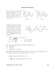
Transients (V)<br />
W melt layer motion under ELM heat loads at QSPA facility (∆t=0.5 ms)<br />
<strong>ITER</strong><br />
Q=1.0 MJ/m 2<br />
0.2<br />
0.1<br />
After 80 ELMs<br />
z,mm<br />
0<br />
1<br />
2<br />
Q=1.5 MJ/m 2<br />
Direction of<br />
plasma impact<br />
0.1<br />
-0.1<br />
-0.2<br />
20<br />
16<br />
12<br />
8<br />
4<br />
0 2 4 6 8 10<br />
y,mm<br />
Mass loss <strong>and</strong> mean erosion<br />
0.5<br />
mass loss<br />
0.4<br />
Averaged erosion<br />
0.3<br />
0.2<br />
0.1<br />
Erosion, µm/shot<br />
Profiles after 100 shots<br />
Number of shots<br />
• W melt layer <strong>for</strong>ms at the edge <strong>and</strong> shifts with<strong>in</strong> an <strong>in</strong>dividual macro-brush element<br />
along plasma stream direction but does not close the gaps;<br />
• average erosion did not exceed 0.2 µm per shot (evaporation, no melt losses);<br />
• maximal roughness of surface reaches 0.3 mm after 100 pulses @ ~1.5 MJ/m 2 ;<br />
• modell<strong>in</strong>g prediction <strong>in</strong> good agreement with experimental results.<br />
0<br />
0 20 40 60 80 100<br />
0<br />
G. Federici, <strong>ITER</strong> Garch<strong>in</strong>g 9 th Course on Technology of <strong>Fusion</strong> Tokamak <strong>Reactors</strong>, Erice, July 26- August 1, 2004<br />
11
Transients (VI)<br />
Thermal quench disruptions<br />
• Energy deposition not only <strong>in</strong> the divertor (Wdiv
Transients (VII)<br />
Specifications <strong>for</strong> thermal quench need revisit<strong>in</strong>g<br />
Current <strong>ITER</strong> thermal quench specifications (very conservative)<br />
• W th = 350 MJ, duration ~ 1 ms<br />
• ∆W div<br />
disruption<br />
/W th ~ 1<br />
• Broaden<strong>in</strong>g ~ 3 (very small)<br />
100<br />
G. Federici, <strong>ITER</strong>, 30.09.2003.<br />
8000<br />
7000<br />
6000<br />
5000<br />
4000<br />
Tungsten<br />
10 MJ/m 2<br />
1 ms<br />
B = 5 T, α = 2 0<br />
Hassane<strong>in</strong>, A., J. Nucl. Mater. 273<br />
(1999) 326.<br />
T s<br />
Melted Thickness ( µm)<br />
<strong>ITER</strong><br />
1000<br />
100<br />
10<br />
3000<br />
Disruption energy density, MJám -2<br />
10<br />
1<br />
Current <strong>ITER</strong> specifications<br />
∆W div<br />
/W dia<br />
=10%<br />
∆W div<br />
/W dia<br />
=100%<br />
∆W div<br />
/W dia<br />
=50%<br />
G. Federici, TPB Nov. to appear<br />
Region of 'no'<br />
melt<strong>in</strong>g of W<br />
<strong>for</strong> disruptions<br />
last<strong>in</strong>g 1 ms<br />
0.1<br />
0 5 10 15 20<br />
SOL broaden<strong>in</strong>g dur<strong>in</strong>g disruptions λ mid(dis)<br />
/ λ mid(ss)<br />
0 25 50 75 100<br />
Wetted fraction of <strong>ITER</strong> divertor target (%)<br />
Region of 'no'<br />
melt<strong>in</strong>g of W<br />
<strong>for</strong> disruptions<br />
last<strong>in</strong>g 10 ms<br />
2000<br />
1000<br />
Vaporization Thickness ( µm)<br />
0<br />
0.1<br />
10 0 10 1 10 2 10 3<br />
Time, µs<br />
• Important driver <strong>for</strong> lifetime of W<br />
divertor target <strong>in</strong> <strong>ITER</strong><br />
Concern rema<strong>in</strong>s on whether<br />
generation dur<strong>in</strong>g ELMs, disruptions<br />
of surface irregularities <strong>in</strong> tungsten<br />
due to melt<strong>in</strong>g, <strong>and</strong> <strong>in</strong> CFC due to<br />
brittle destruction, might <strong>for</strong>m hot<br />
spots dur<strong>in</strong>g normal operation.<br />
1<br />
G. Federici, <strong>ITER</strong> Garch<strong>in</strong>g 9 th Course on Technology of <strong>Fusion</strong> Tokamak <strong>Reactors</strong>, Erice, July 26- August 1, 2004<br />
13
CHEMICAL EROSION YIELD (C/ion)<br />
10 -3<br />
Stationary Issues (I)<br />
C-erosion dur<strong>in</strong>g normal operation<br />
Reduction of source of carbon (chemical sputter<strong>in</strong>g) :<br />
• Flux dependence, high target temp;<br />
• Fluence dependence (DIII-D, PISCES-B);<br />
• Dop<strong>in</strong>g.<br />
J. Roth et al.<br />
Data after calibration <strong>and</strong> normalisation to 30 eV<br />
10 -1 Ion Beams IPP<br />
10 -2 PSI1<br />
JT-60U outer div<br />
ToreS 2001<br />
ToreS 2002<br />
TEXTOR<br />
PISCES<br />
JET 2001<br />
10 19 10 20 10 21 10 22 10 23 10 24<br />
ION FLUX (at/m 2 s)<br />
J. Roth (IPP Garch<strong>in</strong>g) Nuclear <strong>Fusion</strong> 2004<br />
Reduction of Y C<br />
chem<br />
at high fluences<br />
accompanied by<br />
surface modifications<br />
T surf<br />
~ 440 o C<br />
PISCES-B<br />
R. Doerner, K. Schmid, et al.<br />
<strong>ITER</strong><br />
G. Federici, <strong>ITER</strong> Garch<strong>in</strong>g 9 th Course on Technology of <strong>Fusion</strong> Tokamak <strong>Reactors</strong>, Erice, July 26- August 1, 2004<br />
14
Stationary issues (II)<br />
Carbon erosion dur<strong>in</strong>g normal operation<br />
<strong>ITER</strong><br />
C necessary to radiate power <strong>in</strong> the divertor –<br />
•Y C<br />
chem<br />
~ 1% P RAD<br />
/P SOL<br />
~ 0.6<br />
• If Y C<br />
chem<br />
Stationary Issues (III)<br />
Ma<strong>in</strong> chamber erosionD 0,+ , Z n+ fluxes sputter walls<br />
<strong>ITER</strong><br />
• impurity source<br />
• divertor deposition<br />
Scal<strong>in</strong>g neutral erosion<br />
of W walls AUG <strong>ITER</strong><br />
What determ<strong>in</strong>es D 0,+ fluxes<br />
• D 0 escape via divertor plasma<br />
• D 2<br />
gas puff<br />
• D 2<br />
bypass leaks<br />
→ Predictable<br />
+ Controllable<br />
Kukushk<strong>in</strong><br />
Coster<br />
Chen<br />
• Ion flux to ma<strong>in</strong> walls due to:<br />
- Far SOL transport (C-Mod)<br />
- Flux due to ELMs<br />
Matthews, PSI 2004<br />
G. Federici, <strong>ITER</strong> Garch<strong>in</strong>g 9 th Course on Technology of <strong>Fusion</strong> Tokamak <strong>Reactors</strong>, Erice, July 26- August 1, 2004<br />
16
Stationary Issues (IV)<br />
Ma<strong>in</strong> chamber erosionD 0,+ , Z n+ fluxes sputter walls<br />
<strong>ITER</strong><br />
Eroded Be will deposit <strong>in</strong> the divertor <strong>and</strong> then …….<br />
8.0<br />
4.0<br />
2.0<br />
18.0<br />
14.0<br />
Erosion rate (mm/FPY)<br />
0.001 0.01 0.1 1 10<br />
Low-Z (erode 10-100 times faster)<br />
i Be<br />
i<br />
i i<br />
i<br />
m o C<br />
o<br />
m m<br />
o<br />
m<br />
m o<br />
s<br />
s<br />
l<br />
s<br />
High-Z<br />
l<br />
s<br />
l<br />
Cu<br />
Mo<br />
W<br />
l<br />
l<br />
o<br />
s<br />
m<br />
i<br />
i<br />
mo<br />
sl<br />
l<br />
G. Federici, et al. JNM 290-293 (2001) 260.<br />
‣ Be peak erosion rate of ~0.1<br />
nm/s (~0.3 cm/burn-yr) is<br />
acceptable <strong>for</strong> the low dutyfactor<br />
operation of <strong>ITER</strong>, but<br />
not <strong>for</strong> a reactor.<br />
Erosion<br />
(g/<strong>ITER</strong> pulse)<br />
Co-deposition<br />
(g-T//<strong>ITER</strong><br />
pulse)<br />
Be 27
Stationary Issues (V)<br />
Effects of Be deposition at the carbon target<br />
<strong>ITER</strong><br />
A small Be impurity concentration (~0.2%) <strong>in</strong> the plasma causes Be surface<br />
layers to <strong>for</strong>m, suppress<strong>in</strong>g both chemical <strong>and</strong> physical erosion of carbon<br />
-50 V bias, 200ºC, T e<br />
= 8 eV, n e<br />
= 3 e 12 cm -3<br />
4000<br />
Chemical erosion<br />
Physical sputter<strong>in</strong>g<br />
3500<br />
3000<br />
CD b<strong>and</strong><br />
No Be <strong>in</strong>jection<br />
0.2% Be ion concentration<br />
2.4 10 4<br />
2.8 10 4 400 450 500 550 600<br />
No Be <strong>in</strong>jection<br />
0.2% Be ion concentration<br />
2500<br />
D gamma<br />
Be I<br />
2 10 4<br />
2000<br />
1500<br />
1.6 10 4<br />
1.2 10 4<br />
C I<br />
1000<br />
500<br />
8000<br />
4000<br />
200 400 600 800 1000<br />
pixel number<br />
K. Schmid (IPP-Garch<strong>in</strong>g),<br />
R. Doerner (UCSD)<br />
pixel number<br />
• <strong>ITER</strong> is expected to have ~1-10% Be concentration <strong>in</strong> the divertor plasma, but<br />
several open questions rema<strong>in</strong>:<br />
Be-deposition/Be-diffusion (high T surf )<br />
Behaviour <strong>for</strong> (Ne, Ar) seed<strong>in</strong>g<br />
Power h<strong>and</strong>l<strong>in</strong>g/transient power loads<br />
In/out coverage asymmetries <br />
A tokamak demonstration<br />
under <strong>ITER</strong> relevant<br />
conditions is urgently needed<br />
G. Federici, <strong>ITER</strong> Garch<strong>in</strong>g 9 th Course on Technology of <strong>Fusion</strong> Tokamak <strong>Reactors</strong>, Erice, July 26- August 1, 2004<br />
18
Predictions of Tritium Co-deposition <strong>in</strong> <strong>ITER</strong><br />
Extrapolation from exist<strong>in</strong>g C-mach<strong>in</strong>es is very difficult<br />
<strong>ITER</strong><br />
• Predictions still uncerta<strong>in</strong> due to<br />
– chemical erosion yields at high temp. <strong>and</strong> fluxes,<br />
– contribution of type I ELMs,<br />
– effects of gaps,<br />
– effects of mixed materials,<br />
– lack of code validation <strong>in</strong> detached plasma.<br />
Note:<br />
– <strong>ITER</strong> predicted rate is 10x less than that <strong>in</strong> JET<br />
– Model underestimates JET retention by factor x40.<br />
• T issues will be heavily scrut<strong>in</strong>ised by<br />
authorities.<br />
• Scale-up of removal rate required is 10 4 .<br />
• Potential options <strong>for</strong> T removal techniques <strong>for</strong> <strong>ITER</strong>.<br />
1) Remove whole co-deposit by:<br />
• oxidation (maybe aided by RF)<br />
• ablation with pulsed energy (laser or flashlamp).<br />
2) Release T by break<strong>in</strong>g C:T chemical bond:<br />
• Isotope exchange<br />
• Heat<strong>in</strong>g to high temperatures e.g. by laser, or ...<br />
Tritium codeposition (g-T)<br />
600<br />
400<br />
200<br />
0<br />
JET<br />
equivalent<br />
10 g/<br />
pulse<br />
In-vessel limit<br />
licens<strong>in</strong>g<br />
5 g/<br />
pulse<br />
0 50 100 150 200<br />
Number of <strong>ITER</strong> pulses, 400 sec. each<br />
• Constra<strong>in</strong>ts:<br />
<strong>ITER</strong>-FEAT<br />
model<strong>in</strong>g predictions<br />
Brooks et al.,<br />
Brooks et al., PSI 2000<br />
2-5 g-T/<strong>ITER</strong> pulse<br />
2-5 g-T / pulse<br />
2 g/pulse<br />
1 g/pulse<br />
Roth et al., PSI 2004<br />
Stationary Issues (VI)<br />
C -deposition <strong>in</strong> remote areas<br />
<strong>ITER</strong><br />
BAFFLE<br />
First-wall/blanket modules<br />
X=0.6 m (top of CFC)<br />
Divertor baffle<br />
)<br />
1<br />
2<br />
TARGET<br />
X=0 (separatrix)<br />
Divertor dome<br />
Divertor target<br />
Pump<strong>in</strong>g duct<br />
Cryopump<br />
X<br />
X=-0.2 m<br />
Divertor l<strong>in</strong>er<br />
(b)<br />
to private region<br />
back on plate<br />
Entrance from<br />
the plasma<br />
Divertor cassettes<br />
<strong>in</strong>ner volume<br />
R<strong>in</strong>g collector<br />
Detail X<br />
Federici, PSI 2004<br />
Pump<strong>in</strong>g port<br />
Exit to the cryopump<br />
G. Federici, <strong>ITER</strong> Garch<strong>in</strong>g 9 th Course on Technology of <strong>Fusion</strong> Tokamak <strong>Reactors</strong>, Erice, July 26- August 1, 2004<br />
20
Stationary Issues (VII)<br />
C -deposition <strong>in</strong> remote areas<br />
Deposition <strong>in</strong> the various regions of the<br />
model <strong>for</strong> different values of stick<strong>in</strong>g - 1 Pa.<br />
ASDEX Upgrade<br />
<strong>ITER</strong><br />
R = Reflected<br />
Balance %<br />
0. 20. 40. 60. 80.<br />
P = Pumped<br />
P = 1.0 Pa<br />
s = 10 -4<br />
10 -3<br />
10 -2<br />
10 -1<br />
0.9<br />
R 1 2 3 4 P<br />
Φ/Φ <strong>in</strong><br />
0.000 0.005 0.010 0.015<br />
Z [m]<br />
0. 2.<br />
10 -2<br />
4<br />
1. 2. 3. 4. 5. 6. 7. 8. 9.<br />
X [m]<br />
10 -1 P = 1.0 Pa<br />
Federici, PSI 2004<br />
Rohde, PSI 2004<br />
s = 10 -4<br />
10 -3<br />
10 -2<br />
10 -1<br />
0.9<br />
1. 2. 3. 4. 5. 6. 7. 8. 9.<br />
X [m]<br />
• In agreement with experimental f<strong>in</strong>d<strong>in</strong>gs <strong>in</strong> exist<strong>in</strong>g tokamaks we f<strong>in</strong>d that:<br />
Deposition<br />
pattern along the<br />
duct <strong>for</strong> different<br />
values of stick<strong>in</strong>g<br />
at 1 Pa.<br />
majority of radical species enter<strong>in</strong>g the divertor private regions will stick on the nearby surfaces<br />
(i.e., underneath the dome or <strong>in</strong> the sub-divertor region);<br />
only a small fraction of low stick<strong>in</strong>g probability species can enter the pump<strong>in</strong>g duct;<br />
only species with very low stick<strong>in</strong>g probabilities (≤10 -3 ) can reach the pump.<br />
G. Federici, <strong>ITER</strong> Garch<strong>in</strong>g 9 th Course on Technology of <strong>Fusion</strong> Tokamak <strong>Reactors</strong>, Erice, July 26- August 1, 2004<br />
21
Stationary Issues (VIII)<br />
C -deposition <strong>in</strong> PFC gaps<br />
<strong>ITER</strong><br />
<strong>ITER</strong> Vertical Target<br />
W<br />
Local<br />
carbon<br />
source<br />
New castellated<br />
limiter<br />
Experiments on TEXTOR<br />
The castellated limiter with <strong>ITER</strong>-like<br />
geometry of cells was exposed to<br />
plasma <strong>in</strong> TEXTOR to assess the fuel<br />
accumulation <strong>in</strong> the gaps.<br />
CFC<br />
CFC Monoblock<br />
General parameters:<br />
N e<br />
=(3.5=>4.3)*10 13 cm -3 ;<br />
I plasma<br />
=350 kA; B t<br />
=2.25 T;<br />
NBI1=1.2 MW; 39 effective shots;<br />
<strong>Plasma</strong> duration 219 seconds;<br />
Radial position: R=47.5 cm T lim<br />
=200-260 0 C<br />
Photo: castellated limiter after exposure <strong>in</strong><br />
TEXTOR. Dimensions of castellation:<br />
10x10x10 mm, gaps width 0.5 mm.<br />
Gaps conta<strong>in</strong> at least 30% of fuel deposited<br />
on plasma-fac<strong>in</strong>g surfaces<br />
V. Philipps, A Litnovsky (FZJ)<br />
G. Federici, <strong>ITER</strong> Garch<strong>in</strong>g 9 th Course on Technology of <strong>Fusion</strong> Tokamak <strong>Reactors</strong>, Erice, July 26- August 1, 2004<br />
22
What Materials Strategy towards a Reactor (I)<br />
<strong>ITER</strong> should be an essential element <strong>in</strong> validat<strong>in</strong>g this strategy<br />
<strong>ITER</strong><br />
• Low-Z materials are “marg<strong>in</strong>ally acceptable” <strong>for</strong> <strong>ITER</strong> but clearly <strong>in</strong>adequate<br />
<strong>for</strong> a DEMO <strong>and</strong> future fusion power reactors.<br />
– CFC chemical erosion, sublimation <strong>and</strong> tritium co-deposition<br />
• Short erosion lifetime<br />
• Needs efficient technique to m<strong>in</strong>imise/recover tritium <strong>in</strong> the co-deposited layers<br />
– Be low melt<strong>in</strong>g po<strong>in</strong>ts limit its application to the ma<strong>in</strong> chamber wall<br />
• Erosion dur<strong>in</strong>g mitigated disruptions/VDE<br />
• Moderate erosion <strong>and</strong> material mix<strong>in</strong>g <strong>in</strong> the divertor.<br />
• W is seen by many as the only credible c<strong>and</strong>idate. None the less, much<br />
work is still needed. Ma<strong>in</strong> problems with W are:<br />
– Power exhaust without C-radiation <strong>in</strong> the divertor.<br />
– HHFCs technology is ready to 20 MW/m 2 (water actively cooled).<br />
• The absence of carbon as low Te divertor radiator requires <strong>and</strong> active control of<br />
the radiated power with seeded impurities<br />
– Melt<strong>in</strong>g <strong>and</strong> surface irregularity as a result of thermal transient events.<br />
– Erosion <strong>and</strong> control of W impurity content to prevent plasma contam<strong>in</strong>ation.<br />
• Cw ≥10 -4 <strong>in</strong> the central plasma would lead to unduly high radiation losses that<br />
would prevent ignition.<br />
• <strong>ITER</strong> should be an essential element <strong>in</strong> validat<strong>in</strong>g this strategy.<br />
G. Federici, <strong>ITER</strong> Garch<strong>in</strong>g 9 th Course on Technology of <strong>Fusion</strong> Tokamak <strong>Reactors</strong>, Erice, July 26- August 1, 2004<br />
23
What Materials Strategy towards a Reactor (II)<br />
Risks <strong>and</strong> benefits!<br />
• As preparation <strong>for</strong> DEMO, <strong>ITER</strong> would probably have to test a high Z first wall.<br />
• In pr<strong>in</strong>ciple there is no technical problem with <strong>in</strong>creas<strong>in</strong>g the W coverage of the<br />
<strong>ITER</strong> first wall but that the physics implications are not yet clear.<br />
• If we start as we plan with a different option we need to replace the 1st wall.<br />
Risks<br />
Option 1: Start with Be<br />
Change-out of the whole first-wall is a very challeng<strong>in</strong>g task.<br />
oTechnical feasibility issues, consequences on mach<strong>in</strong>e downtime<br />
oRemote h<strong>and</strong>l<strong>in</strong>g optimisation<br />
oCost <strong>and</strong> mach<strong>in</strong>e down-time implications<br />
<strong>ITER</strong><br />
<br />
Uncerta<strong>in</strong>ties of T retention <strong>and</strong> mixed-materials dur<strong>in</strong>g early operation.<br />
Show-stoppers<br />
Option 2: Start with W (everywhere) only <strong>in</strong> comb<strong>in</strong>ation with better control of ELMs<br />
<strong>and</strong> disruptions (Promis<strong>in</strong>g results from ASDEX Upgrade <strong>and</strong> other tokamaks)<br />
Need to develop compatible operat<strong>in</strong>g scenarios.<br />
Accept a possible reduction of <strong>ITER</strong> operat<strong>in</strong>g space.<br />
G. Federici, <strong>ITER</strong> Garch<strong>in</strong>g 9 th Course on Technology of <strong>Fusion</strong> Tokamak <strong>Reactors</strong>, Erice, July 26- August 1, 2004<br />
24
What are the Ma<strong>in</strong> Problems with High-Z (I)<br />
<strong>Plasma</strong> contam<strong>in</strong>ation <strong>and</strong> melt<strong>in</strong>g<br />
<strong>ITER</strong><br />
High sputter threshold <strong>for</strong><br />
high Z low erosion<br />
Ion impact energy<br />
E i = 3ZT e + 2T i<br />
• Very low target erosion<br />
<strong>in</strong> C-Mod (Mo) 4.5mm<br />
Prompt re-deposition also<br />
helps high Z at divertor<br />
per year (cont<strong>in</strong>uous) at<br />
outer strike po<strong>in</strong>t<br />
• In ASDEX <strong>and</strong> C-Mod<br />
erosion dom<strong>in</strong>ated by<br />
impurity sputter<strong>in</strong>g<br />
W + W<br />
C-Mod Mo<br />
divertor baffles<br />
Melt<strong>in</strong>g<br />
ASDEX, C-Mod<br />
Control of steady-state <strong>and</strong><br />
transient power loads<br />
essential <strong>in</strong> <strong>ITER</strong><br />
G. Matthews, PSI 2004<br />
ASDEX Upgrade W<br />
Upper divertor tile<br />
G. Federici, <strong>ITER</strong> Garch<strong>in</strong>g 9 th Course on Technology of <strong>Fusion</strong> Tokamak <strong>Reactors</strong>, Erice, July 26- August 1, 2004<br />
25
What are the Ma<strong>in</strong> Problems with High-Z (III)<br />
What is the ion impact energy dur<strong>in</strong>g ELMs at the wall<br />
<strong>ITER</strong><br />
Increased erosion of high Z walls <strong>in</strong> large tokamaks<br />
Plasmoid model has<br />
been fitted to JET data<br />
Fundamenski, PPCF2004<br />
T + W<br />
1% Yield<br />
Ion impact<br />
energy E i<br />
+<br />
T W<br />
Threshold<br />
Limiter probes give v ⊥<br />
≈ 1km/s (similar value<br />
predicted <strong>for</strong> <strong>ITER</strong>)<br />
G. Matthews, PSI 2004<br />
G. Federici, <strong>ITER</strong> Garch<strong>in</strong>g 9 th Course on Technology of <strong>Fusion</strong> Tokamak <strong>Reactors</strong>, Erice, July 26- August 1, 2004<br />
26
What are the Ma<strong>in</strong> Problems with High-Z (II)<br />
Control of W concentration <strong>in</strong> ASDEX Upgrade<br />
<strong>ITER</strong><br />
W eroded by impurities<br />
ma<strong>in</strong>ly limiter phase<br />
• Step-by-step <strong>in</strong>crease of W-<br />
coated plasma fac<strong>in</strong>g<br />
components towards a<br />
Carbon free ASDEX-<br />
Upgrade.<br />
• At present, 65% of total area<br />
of PFCs is made of W.<br />
W migration <strong>in</strong> ASDEX - Upgrade<br />
Krieger, PSI 2004<br />
Total C Deposition<br />
220Kg / year same as JET<br />
Ralph Dux, PSI 2004<br />
G. Federici, <strong>ITER</strong> Garch<strong>in</strong>g 9 th Course on Technology of <strong>Fusion</strong> Tokamak <strong>Reactors</strong>, Erice, July 26- August 1, 2004<br />
27
What are the Ma<strong>in</strong> Problems with High-Z (II)<br />
Control of W concentration <strong>in</strong> ASDEX Upgrade<br />
<strong>ITER</strong><br />
• C is still ma<strong>in</strong> impurity: typically 1% level<br />
• W concentrations (critical value of 10 -4 <strong>in</strong><br />
reactor): typ. neoclassical<br />
accumulation of W)<br />
• Use central heat<strong>in</strong>g by ECRH/ICRH.<br />
Ralph Dux, A. Kallenbach, PSI 2004<br />
G. Federici, <strong>ITER</strong> Garch<strong>in</strong>g 9 th Course on Technology of <strong>Fusion</strong> Tokamak <strong>Reactors</strong>, Erice, July 26- August 1, 2004<br />
28
Open Questions <strong>and</strong> Future Work<br />
Still few years be<strong>for</strong>e start<strong>in</strong>g PFC material procurement <strong>for</strong> <strong>ITER</strong><br />
<strong>ITER</strong><br />
• Type I ELM <strong>and</strong> disruption heat loads - energy loss, energy to divertor <strong>and</strong> wall,<br />
duration, broaden<strong>in</strong>g, impurities, etc.<br />
• Control/mitigation of ELMs <strong>and</strong> disruptions.<br />
• Damage effects due to disruptions (<strong>and</strong> mitigated disruptions) <strong>and</strong> ELMs.<br />
• Mixed material effects: erosion, T-codeposition, T-removal.<br />
• The issue of operation with an all metal wall (high or low Z) <strong>and</strong> no carbon still<br />
needs to be explored <strong>in</strong> current mach<strong>in</strong>es <strong>and</strong> scaled with mach<strong>in</strong>e size.<br />
• Modell<strong>in</strong>g of W as option <strong>for</strong> <strong>ITER</strong> first wall <strong>and</strong> divertor:<br />
– <strong>in</strong>vestigate issues of plasma compatibility, per<strong>for</strong>mance dur<strong>in</strong>g various phases of<br />
operation aris<strong>in</strong>g from use of W <strong>in</strong> <strong>ITER</strong> on: start-up limiter/ full W target/ ma<strong>in</strong> wall.<br />
• Validation/improvement of C erosion/deposition codes.<br />
• Mitigation of co-deposition (temperature tailor<strong>in</strong>g, reactive species (N2)).<br />
• Carbon removal from hidden areas - e.g. bak<strong>in</strong>g with oxygen.<br />
• <strong>Plasma</strong> <strong>in</strong>teraction with irregular <strong>and</strong>/or molten W surfaces.<br />
• PMI measurements/diagnostics.<br />
G. Federici, <strong>ITER</strong> Garch<strong>in</strong>g 9 th Course on Technology of <strong>Fusion</strong> Tokamak <strong>Reactors</strong>, Erice, July 26- August 1, 2004<br />
29
<strong>ITER</strong><br />
ELMs<br />
Matthews, PSI 2004<br />
Conclud<strong>in</strong>g remarks<br />
Opportunities <strong>and</strong> challenges<br />
• Some risk to construct <strong>ITER</strong> without first test<strong>in</strong>g<br />
proposed material mix <strong>in</strong> exist<strong>in</strong>g tokamaks (Be<br />
wall <strong>in</strong> JET <strong>and</strong> full-W ASDEX-U). Now is the<br />
right time!!!<br />
• Accord<strong>in</strong>g to <strong>ITER</strong> construction plans, still few<br />
years rema<strong>in</strong> <strong>for</strong> further R&D <strong>and</strong> physics <strong>in</strong>put to<br />
divertor/first-wall design <strong>and</strong> PFM choices.<br />
<strong>ITER</strong><br />
DEMO<br />
• Disruptions <strong>and</strong> ELMs will be strictly regulated <strong>in</strong><br />
<strong>ITER</strong> <strong>and</strong> not permitted <strong>in</strong> DEMO.<br />
– Materials protection schemes <strong>ITER</strong> operat<strong>in</strong>g<br />
<strong>in</strong>structions<br />
• Low-Z materials are “marg<strong>in</strong>ally acceptable” <strong>for</strong><br />
<strong>ITER</strong> but clearly <strong>in</strong>adequate <strong>for</strong> DEMO.<br />
• W is seen by many as the only credible<br />
c<strong>and</strong>idate. Nonetheless, much work still needed.<br />
• Erosion <strong>and</strong> control of W impurity content to<br />
prevent plasma contam<strong>in</strong>ation is one of the<br />
toughest problems.<br />
– Transient free cold edge <strong>for</strong> DEMO<br />
• Also brittleness <strong>in</strong> a neutron environment needs<br />
improvement.<br />
• <strong>ITER</strong> should be an essential element <strong>in</strong> validat<strong>in</strong>g<br />
strategy towards DEMO, <strong>and</strong> probably will need<br />
to test a W first-wall.<br />
G. Federici, <strong>ITER</strong> Garch<strong>in</strong>g 9 th Course on Technology of <strong>Fusion</strong> Tokamak <strong>Reactors</strong>, Erice, July 26- August 1, 2004<br />
30