Laser-Distance-Sensor - Iberica de Automatismos
Laser-Distance-Sensor - Iberica de Automatismos
Laser-Distance-Sensor - Iberica de Automatismos

Create successful ePaper yourself
Turn your PDF publications into a flip-book with our unique Google optimized e-Paper software.
ELTROTEC<br />
<strong>Sensor</strong> GmbH<br />
Heinkelstrasse 2<br />
D-73066 Uhingen<br />
Telefon: 07161 / 98872-300<br />
Telefax: 07161 / 98872-303<br />
Internet:www.Eltrotec.com<br />
e-mail: Info@Eltrotec.com<br />
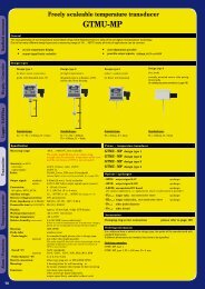
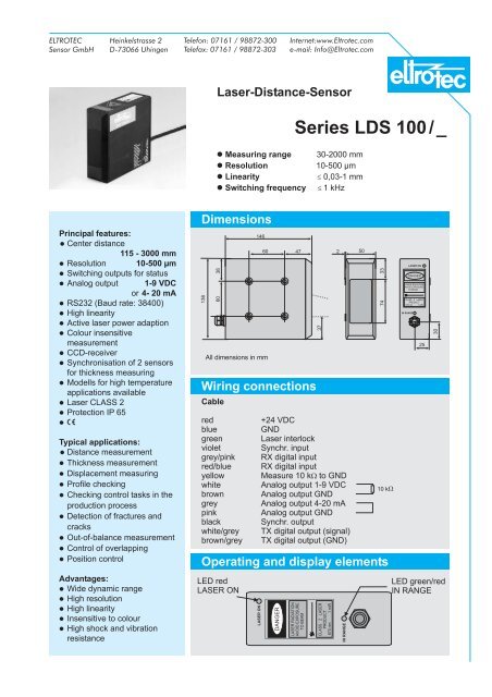
<strong>Laser</strong>-<strong>Distance</strong>-<strong>Sensor</strong><br />
Measuring range 30-2000 mm<br />
Resolution<br />
10-500 µm<br />
Linearity<br />
£ 0,03-1 mm<br />
Switching frequency £ 1 kHz<br />
Series LDS 100 / _<br />
Principal features:<br />
Center distance<br />
115 - 3000 mm<br />
Resolution 10-500 µm<br />
Switching outputs for status<br />
Analog output 1-9 VDC<br />
or 4- 20 mA<br />
RS232 (Baud rate: 38400)<br />
High linearity<br />
Active laser power adaption<br />
Colour insensitive<br />
measurement<br />
CCD-receiver<br />
Synchronisation of 2 sensors<br />
for thickness measuring<br />
Mo<strong>de</strong>lls for high temperature<br />
applications available<br />
<strong>Laser</strong> CLASS 2<br />
Protection IP 65<br />
¢<br />
Typical applications:<br />
<strong>Distance</strong> measurement<br />
Thickness measurement<br />
Displacement measuring<br />
Profile checking<br />
Checking control tasks in the<br />
production process<br />
Detection of fractures and<br />
cracks<br />
Out-of-balance measurement<br />
Control of overlapping<br />
Position control<br />
Advantages:<br />
Wi<strong>de</strong> dynamic range<br />
High resolution<br />
High linearity<br />
Insensitive to colour<br />
High shock and vibration<br />
resistance<br />
Dimensions<br />
136<br />
38<br />
60<br />
146<br />
All dimensions in mm<br />
60 47<br />
Wiring connections<br />
Cable<br />
red<br />
+24 VDC<br />
blue<br />
GND<br />
green <strong>Laser</strong> interlock<br />
violet Synchr. input<br />
grey/pink RX digital input<br />
red/blue RX digital input<br />
yellow Measure 10 kW<br />
to GND<br />
white Analog output 1-9 VDC<br />
brown Analog output GND<br />
grey<br />
Analog output 4-20 mA<br />
pink<br />
Analog output GND<br />
black Synchr. output<br />
white/grey TX digital output (signal)<br />
brown/grey TX digital output (GND)<br />
Operating and display elements<br />
LED red<br />
LASER ON<br />
LASER ON<br />
DANGER<br />
LASER RADIATION<br />
AVOID EXPOSURE<br />
TO BEAM<br />
37<br />
CLASS 2 LASER<br />
PRODUCT<br />
670 nm 1mW<br />
2<br />
IN RANGE<br />
50<br />
33<br />
74<br />
10 kW<br />
IN RANGE<br />
LASER ON<br />
DANGER<br />
LASER RADIATION<br />
AVOID EXPOSURE<br />
TO BEAM<br />
CLASS 2 LASER<br />
PRODUCT<br />
670 nm 1 mW<br />
25<br />
30<br />
LED green/red<br />
IN RANGE
Technical data<br />
Electrical data<br />
Lightsource<br />
Data on ambiente<br />
conditions<br />
Supply voltage 24 VDC +/-10%<br />
Power consumption<br />
~ 4.5 W typ.<br />
Measuring / testing frequency<br />
0.5 /1kHz<br />
Analog output<br />
1-9 VDC<br />
4-20 mA<br />
Serial output RS232 (Baudrate: 38400)<br />
Cable<br />
7x2x0.14 mm², shiel<strong>de</strong>d, 2.5 m length<br />
<strong>Laser</strong>, Wave length<br />
typ. 670 nm<br />
<strong>Laser</strong> power<br />
< 1 mW<br />
<strong>Laser</strong> CLASS 2 (EN 60825-1:1994)<br />
Max. operating temperature 0 to +45 °C<br />
Max. storage temperature -20 to + 70 °C<br />
Max. rel.humidity<br />
90% (not con<strong>de</strong>nsing)<br />
Protection IP 65<br />
Specifical data <strong>Sensor</strong> LDS 100/...<br />
30 100 200 300 500 700 900 900/M 1400 2000<br />
Sensing range from 100 100 100 100 200 400 700 1500 700 2000<br />
(mm) up to 130 200 300 400 700 1100 1600 2400 2100 4000<br />
Center distance 115 150 200 250 450 750 1150 1950 1400 3000<br />
Spot Ø mm 1 1 1-2 1-2 1-2 1-2 4 5 5 5<br />
Resolution* mm 0.002 0.01** 0.05 0.25 0.1 0.5 0.1 0.3 0.2 0.5<br />
Linearity* +/- mm 0.03 0.1 0.3 0.45 0.5 1.05 0.9 1.0 1.4 1.0<br />
Reproduceability* mm 0.01 0.01** 0.05 0.25 0.1 0.5 0.1 0.3 0.2 0.5<br />
Temp.drift +/- µm/°C 9 30 60 90 150 210 270 270 420 600<br />
Dimensions<br />
Weight<br />
136x146x50mm<br />
approx. 1.6 kg<br />
230x70x200mm<br />
approx. 3.6 kg<br />
* Static measurement on white paper ** Specification for digital output; analog output: 0.05 mm<br />
Or<strong>de</strong>ring information<br />
Part No.<br />
10652067<br />
10652068<br />
10652069<br />
10652070<br />
10652071<br />
10652072<br />
10652073<br />
10652075<br />
10652074<br />
10652076<br />
ELT/LDS/LDS100E5<br />
Application<br />
Contour control<br />
Application<br />
Diameter check<br />
Presented by:<br />
LASER CLASS 2<br />
EN 60825-1:1994<br />
Do not stare<br />
into beam!<br />
© Eltrotec 07/06 (we reserve the right to make changes in the interest of technical progress)
ELTROTEC<br />
<strong>Sensor</strong> GmbH<br />
Heinkelstrasse 2<br />
D-73066 Uhingen<br />
Telefon: 07161 / 98872-300<br />
Telefax: 07161 / 98872-303<br />
Internet:www.Eltrotec.com<br />
e-mail: Info@Eltrotec.com<br />
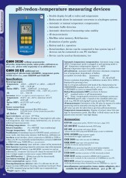
<strong>Laser</strong>-<strong>Distance</strong>-<strong>Sensor</strong><br />
Series LDS 400<br />
Time of flight measurement<br />
Measuring range<br />
300-4000 mm<br />
Digital resolution<br />
³ 0.9 mm<br />
Switching frequency 100 Hz / 500 Hz<br />
2x PNP or NPN, 4-20mA, RS485<br />
Specification:<br />
The LDS 400 series offers an innovative<br />
laser distance sensor with time of<br />
flight measurement. This technology<br />
is based on the measurement of the<br />
time between the emmision and the<br />
receipt of the laser light pulses.<br />
In the 300-4000 mm distance range,<br />
it provi<strong>de</strong>s a very accurate measurement<br />
in<strong>de</strong>pen<strong>de</strong>nt of the target's<br />
colour with 12 bit resolution and high<br />
linearity. A 4-digit display on the<br />
sensors top visualises the value of<br />
the measured distance in mm, as well<br />
as all the parameters that can be set<br />
with three pushbuttons.<br />
The LDS 400 sensors have two<br />
switching outputs, available as PNP<br />
or NPN mo<strong>de</strong>ls, that can be set at<br />
different distances, while the<br />
measurement value ist supplied at<br />
the 4-20 mA analogue output and<br />
RS485 interface. This interface can<br />
also be used to set all the parameters.<br />
A response time selection with 5 ms<br />
normal and 1 ms fast response is<br />
available.<br />
¢<br />
U L<br />
Typical applications:<br />
<strong>Distance</strong> measurement<br />
Thickness measurement<br />
Presence control<br />
Automatic control for<br />
coiling/uncoiling machines<br />
<strong>Distance</strong> measurement for<br />
overhead conveyors<br />
<strong>Distance</strong> measurement up<br />
to 1200 °C hot steel<br />
Advantages:<br />
<br />
<br />
<br />
<br />
<br />
<br />
<br />
Wi<strong>de</strong> measuring range<br />
High linearity<br />
2 switching points<br />
Highly shock- and<br />
vibration-resistant<br />
4-digit display<br />
Connector turnable<br />
Visible laserbeam<br />
Dimensions<br />
18<br />
15.5 40<br />
34<br />
15<br />
All dimensions in mm<br />
Alarm LED red<br />
Wiring connections<br />
6<br />
7 8<br />
5<br />
Output LED yellow<br />
1 2<br />
Operating and display elements<br />
90<br />
2 holes M5<br />
8 mm <strong>de</strong>ep<br />
Plug connector M12<br />
Switching output<br />
indicator LEDs<br />
green<br />
Switching output<br />
LED yellow<br />
4<br />
3<br />
1<br />
2<br />
3<br />
4<br />
5<br />
6<br />
7<br />
8<br />
14.5<br />
73<br />
8<br />
7 22<br />
73<br />
50<br />
M12<br />
64<br />
wh Rx/Tx -<br />
bn +10-30VDC<br />
gn Analogue output<br />
ye Output 1<br />
gr Output 2<br />
pi Rx/Tx +<br />
bl<br />
rd<br />
SET<br />
+ -<br />
GND<br />
SYNC<br />
Fast LED<br />
green<br />
LDS 400<br />
+ pushbutton – pushbutton<br />
SET-pushbutton<br />
LASERSTRAHLUNG<br />
NICHT IN DEN STRAHL BLICKEN<br />
LASERKLASSE 2<br />
P 1 mW; = 670 nm<br />
nach DIN EN 60825-1 03.97<br />
4 digit display<br />
15,5<br />
Ø 5.2<br />
90° turnable
Technical data<br />
Electrical data<br />
Specific data<br />
Outputs<br />
Light source<br />
Ambient<br />
conditions<br />
Housing<br />
Or<strong>de</strong>ring information<br />
<strong>Laser</strong> <strong>Distance</strong> <strong>Sensor</strong><br />
LDS 400/RS485/PNP<br />
LDS 400/RS485/NPN<br />
Supply voltage<br />
15 - 30 VDC<br />
Ripple<br />
max. 2Vpp<br />
Current consumption typ. max. 170 mA (110 mA at 24V)<br />
Data memory<br />
EEPROM<br />
Measuring range<br />
300 - 4000 mm (18% grey to 90% white)<br />
(at specified surf. reflection)<br />
400-2500 (at 6% black)<br />
Digital resolution (RS485)<br />
³ 0.9 mm<br />
Analogue resolution<br />
³ 3 mm<br />
Response time<br />
5 ms (normal), 1 ms (fast)<br />
Switching frequency<br />
100 Hz (normal), 500 Hz (fast)<br />
Linearity typ. 0.3 %<br />
(at 24VDC, at 90% white surface, 25 °C)<br />
Switching outputs<br />
2x PNP or NPN<br />
max. 30 VDC, 100 mA, short circuit protected<br />
Analogue output<br />
4-20 mA<br />
Input<br />
SYNC-input, PNP<br />
Serial connection<br />
RS485, 9600 Bd<br />
Wave length<br />
665 nm<br />
<strong>Laser</strong> class 2 (EN 60825-1:1994)<br />
Measuring spot size typ.<br />
~ Ø 12 mm at 2000 mm distance<br />
~ Ø 20 mm at 4000 mm distance<br />
Operating temperature -10 to +50 °C<br />
Storage temperature -20 to + 70 °C<br />
Protection IP 67<br />
Ambient light protection according to EN 60947-5-2<br />
Vibration<br />
0,5 mm amplitu<strong>de</strong>, 10-55 Hz<br />
according to EN 60068-2-6<br />
Shock resistance<br />
11 ms (30 G) , acc.to EN60068-2-27<br />
Material<br />
Aluminium housing, optical elements: Glas<br />
Weight<br />
approx. 330 g<br />
Connections<br />
8-pol plug connector, M12, turnable<br />
Part No.<br />
10652680<br />
10652683<br />
Accessories<br />
Cable 3 m, 8-pin, M12 plug 11232681<br />
Cable 5 m, 8-pin, M12 plug 11232682<br />
Application<br />
<strong>Distance</strong> measurement on paper, coils or films<br />
LDS 400<br />
Presented by:<br />
LASER CLASS 2<br />
EN 60825-1:1994<br />
Do not stare<br />
into beam!<br />
© Eltrotec 07/06 (we reserve the right to make changes in the interest of technical progress) ELT/LDS/LDS400e4
Operating and display elements LDS400<br />
LED indicators on LDS400 frontsi<strong>de</strong><br />
OUTPUT LED<br />
ALARM LED<br />
Yellow LED indicates an active Output<br />
(Output 1 OR Output 2)<br />
The red ALARM LED indicates a missing receiver signal<br />
Pushbuttons and Display on top<br />
Alarm LED red<br />
Output LED yellow<br />
OUTPUT LED Yellow LED indicates an active Output<br />
(Output 1 OR Output 2)<br />
Display (green, 4-digit)<br />
LED OUT1, OUT2<br />
LED FAST<br />
SET-pushbutton<br />
+/- pushbuttons<br />
In normal working mo<strong>de</strong>, the distance in mm is shown on the display<br />
Green LED1 indicates the activated switching output 1<br />
Green LED2 indicates the activated switching output 2<br />
Green LED3 indicates the activated FAST mo<strong>de</strong> (500 Hz)<br />
A short press on this key activates the self-setting procedure.<br />
A long pressure on the key allows the user to access into the mo<strong>de</strong><br />
(FAST/NORM) and the setting of output <strong>de</strong>lay.<br />
Short pressure on this key allows the user to run through<br />
parameters and the settings menu of the sensor.<br />
Long pressure allows to change the switching threshold value. LED yellow<br />
(see also “Switching threshold adjustment ”)<br />
Switching diagram<br />
Switching output<br />
Switching output<br />
indicator LEDs<br />
green<br />
123<br />
SET<br />
+ -<br />
+ Pushbutton<br />
Fast LED<br />
green<br />
Display<br />
4-digit<br />
– Pushbutton<br />
SET-Pushbutton<br />
Analogue output<br />
mA<br />
20<br />
12<br />
4<br />
0<br />
Measuring range<br />
300 4000 mm <strong>Distance</strong><br />
Digital output<br />
V<br />
24<br />
0<br />
Switching<br />
distance<br />
Hysteresis<br />
<strong>Distance</strong><br />
RS485 serial connection<br />
The RS485 serial interface allows the complete remote control of the<br />
sensor. All functions as channel status, normal/fast mo<strong>de</strong> selection or<br />
output <strong>de</strong>lay can be configured by serial connection. The serial<br />
communication parameters are:<br />
9600 baud, non-parity, 8 data bits,1 stop bit.<br />
The SYNC-input is used to <strong>de</strong>termine the communication direction.<br />
SYNC active (LOW)<br />
LDS400 -> user<br />
SYNC passive (HIGH)<br />
user -> LDS400<br />
With SYNC active, the sensor continuously transmits the <strong>de</strong>tected<br />
distance value (with a precision of 12 bit) by means of a binary data<br />
format. 2 byte are used; one with bit 0 at logic level 1 i<strong>de</strong>ntifies the high<br />
byte.<br />
7 0 7 0<br />
0 0 D11 D10 D9 D8 D7 1 D6 D5 D4 D3 D2 D1 D0 0<br />
All the commands have to be sent via terminal in ASCII-format according<br />
to the following:<br />
- Remote configuration:<br />
To access the remote configuration mo<strong>de</strong>, SYNC-input<br />
must be passive. (SYNC passive = HIGH)<br />
The available commands are:<br />
@ beginning of remote setting mo<strong>de</strong><br />
cx channel selection, with x. {1,2}<br />
vxxx distance selection,<br />
with xxxx {0-4095}<br />
bx <br />
MSB<br />
dark/light mo<strong>de</strong> selection, with x {1,2}<br />
b1 = dark-switching<br />
b2 = light-switching<br />
memorisation to the configuration sequence<br />
e <br />
q exit from remote setting mo<strong>de</strong> without saving<br />
At the receipt of the ‘ q’ or ‘e’ -commands, the<br />
sensor visualises ok <br />
LSB<br />
- Delay configuration:<br />
To access the remote configuration mo<strong>de</strong>, SYNC-input must<br />
be passive.<br />
(SYNC passive = HIGH). The available commands are:<br />
@ beginning of <strong>de</strong>lay configuration<br />
dx <strong>de</strong>lay selection with x {0,1,2,3,4,5}<br />
d0=0ms d3=20ms<br />
d1=5ms d4=30ms<br />
d2=10ms d5=40ms<br />
e memorisation of the new <strong>de</strong>lay value<br />
q exit from <strong>de</strong>lay setting mo<strong>de</strong> without saving<br />
At the receipt of the ‘ q’ or ‘e’ -commands, the<br />
sensor visualises ok <br />
- Normal/ fast mo<strong>de</strong> configuration:<br />
To acces the remote configuration mo<strong>de</strong>, SYNC-input must be passive.<br />
(SYNC passive = HIGH). The available commands are:<br />
@ beginning of remote setting mo<strong>de</strong><br />
mx operating mo<strong>de</strong> selection with x {1,2}<br />
m1 = normal<br />
m2 = fast<br />
e execution of configuration sequence<br />
q exit from remote setting mo<strong>de</strong> without saving<br />
At the receipt of the ‘ q’ or ‘e’ -commands, the<br />
sensor visualises ok <br />
- Receipt of the channel status:<br />
At any moment, the receipt of the ‘r’ remote command<br />
(and SYNC passive), the sensor configuration is restored.<br />
NOTE:<br />
The single digits have to be distanced amongst themselves<br />
at least 1 ms, during the command transmission.
Settings LDS400<br />
Setting of the 2 channels<br />
Display<br />
1945<br />
CH-1<br />
1945<br />
1960<br />
saved value<br />
new value<br />
Quick status display<br />
At each pressure of the SET-button, the user can run through the options<br />
of the selected channel. By pressing the SET -button repeatedly, all options<br />
will be visualized sequencially.<br />
Detection<br />
Place the object to <strong>de</strong>tect in front of the sensor.<br />
The actual distance value in mm is shown on display.<br />
1945 <strong>Distance</strong> value<br />
By pressing the SET-button (for at least 2 sec.) you will reach the channel selection.<br />
Channel selection<br />
CH-1<br />
To select the channels, press the +/- - buttons.<br />
You confirm the selection by a short press (0,5 s) of the SET- button and will reach CH-2<br />
the dark/light-selection.<br />
Dark/light-mo<strong>de</strong><br />
LOn Light switching<br />
To select the dark/light mo<strong>de</strong> of the channels, use the +/- -buttons.<br />
dOn<br />
Press the SET - pushbutton again for at least 0,5 sec.<br />
Dark switching<br />
On display, the "updt" message starts to blink ( 4Hz, for 2 s)<br />
updt Settings saved<br />
The <strong>de</strong>tection distance value appears on display, LED for the memorised channel<br />
is active. The +/- -pushbuttons can be used to change the <strong>de</strong>tected distance value. 1945 <strong>Distance</strong> value<br />
(Units change if the pushbuttons pressed repeatedly, the tens if the buttons keep pressed)<br />
Press the SET- button again for at least 0.5 s to end the setting of the channels phase.<br />
Switching threshold adjustment<br />
Channel selection<br />
Press the +/- - button for at least 2 sec. the “CH 1”- message appears.<br />
To select the channels, press the +/- - buttons.<br />
You confirm the selection by a short press (0,5 s) of the SET- button<br />
<strong>Distance</strong> of threshold phase<br />
The previously <strong>de</strong>tected distance value appears. With a press of the +/-<br />
pushbuttons the <strong>de</strong>tected distance value can be changed, (Units change if the<br />
pushbuttons pressed repeatedly, the tens if the buttons keep pressed).<br />
Press the SET- button again for at least 0.5 s to end the threshold adjustment phase.<br />
Setting of the parameter<br />
Press the SET-button for at least 6stoenter into the parameter setting menu.<br />
By pressing the +/- pushbuttons, the user can run up and down within this<br />
menu.<br />
Switching frequency<br />
Use the SET-pushbutton to select the <strong>de</strong>ci<strong>de</strong>d option. Setting of normal or<br />
fast mo<strong>de</strong> is equal to both outputs.<br />
Delay setting<br />
The <strong>de</strong>lay value setting is equal to both channels. When a <strong>de</strong>lay value, different<br />
from zero, is set, outputs are active for at least the time (in ms) as shown in<br />
the display.<br />
Setting: with the SET pushbutton you can run through the available <strong>de</strong>lay steps.<br />
You confirm the selection by pressing the SET- button again.<br />
Memorisation of the parameter set<br />
Pressing the SET-button (the "SAVE"-message blinks for 2 s, 4 Hz) all the changed<br />
values are saved and the user exits from the menu and returns to normal mo<strong>de</strong>.<br />
To return to the setting menu, one of the +/- -buttons has to be pressed.<br />
After a 10 s inactivity of the pushbuttons, the sensor returns to normal mo<strong>de</strong><br />
visualising the disance.<br />
Keylock (SET pushbutton block)<br />
The keylock function is activated after powering on, if the SYNC terminal is connected to the positive<br />
power supply (+VDC) for at least 1 s.<br />
(After the first second, the SYNC signal is available for normal operations)<br />
To <strong>de</strong>activate the keylock function, the sensor has to be turned off and re-powered while maintaining<br />
the SYNC wire not connected or ground connected (GND).<br />
SYNC-Input<br />
The SYNC signal allows to calculate the beginning and the ending instants<br />
of the measurement. Reading cycle beginns after the transition of the SYNC<br />
signal from passive to active and the sensor outputs are updated after<br />
max. 400 µs. All the outputs are <strong>de</strong>activated after max. 400 µs from<br />
the active-passive transition. (SYNC passive=Vcc, SYNC active=GND)<br />
The SYNC wire is also used to <strong>de</strong>termine the transmission direction<br />
when the RS485 serial connection is used.<br />
Passive<br />
SYNC<br />
Aktive<br />
ON<br />
Output<br />
OFF<br />
MEnu<br />
nOrM<br />
FASt<br />
d-00<br />
d-05<br />
d-10<br />
...<br />
d-40<br />
CH-1<br />
1945<br />
LOn<br />
CH-2<br />
...<br />
SAVE<br />
max.<br />
400 µs<br />
normal, 100 Hz<br />
fast, 500 Hz<br />
no <strong>de</strong>lay<br />
5ms<br />
10 ms<br />
20 ms<br />
30 ms<br />
40 ms<br />
max.<br />
400 µs<br />
© Eltrotec 07/06 (we reserve the right to make changes in the interest of technical progress) ELT/LDS/LDS400e4
ELTROTEC<br />
<strong>Sensor</strong> GmbH<br />
Heinkelstrasse 2<br />
D-73066 Uhingen<br />
Telefon: 07161 / 98872-300<br />
Telefax: 07161 / 98872-303<br />
Internet:www.Eltrotec.com<br />
e-mail: Info@Eltrotec.com<br />
<strong>Laser</strong>-<strong>Distance</strong>-<strong>Sensor</strong><br />
<strong>Laser</strong>-Triangulation with<br />
CMOS-Technology<br />
Basic features:<br />
Center distance<br />
40-160 mm<br />
Resolution typ. 4-100 µm<br />
Analogue output 4-20 mA<br />
optional: 1-5 VDC<br />
High linearity<br />
Colour insensitive<br />
measurement<br />
<strong>Laser</strong> Class 2<br />
Protection IP 67<br />
¢<br />
Dimensions<br />
Series LDS 60<br />
Measuring range 20, 50, 100, 200 mm<br />
Resolution<br />
4, 10, 50, 100 µm<br />
Outputs<br />
4-20 mA / 1-5 VDC<br />
Measuring rate 500 Hz<br />
Small dimensions (65 x 50 x 20) mm<br />
Mounting<br />
holes<br />
2x Ø 4,3 / 5,8<br />
<strong>Laser</strong>beam<br />
65<br />
16<br />
57<br />
4<br />
5<br />
50<br />
40<br />
LDS 60<br />
LASERSTRAHLUNG<br />
NICHT IN DEN STRAHL BLICKEN<br />
LASERKLASSE 2<br />
P 1 mW; = 670 nm<br />
nach DIN EN 60825-1 03.97<br />
20<br />
Glass optic<br />
All dimensions in mm<br />
Wiring connections<br />
Typical applications:<br />
<strong>Distance</strong> measurement<br />
Thickness measurement<br />
Positioning of robotic arm<br />
Profile checking<br />
Out-of-balance measurement<br />
Control of overlapping<br />
Position on conveyor<br />
<strong>de</strong>formation<br />
Stroke, oscillation<br />
Advantages:<br />
Metal housing<br />
Small dimensions<br />
High resolution<br />
High linearity<br />
Vibration resistance 15 g/<br />
(10 Hz - 1 kHz)<br />
2<br />
3<br />
1<br />
4<br />
7<br />
5<br />
7 pin plug<br />
rear sight<br />
Description<br />
6<br />
Pin Colour Reference<br />
1 gn Error output, open collector<br />
NPN; switching to GND,<br />
Uce max. 30 VDC,<br />
100 mA, short circuit protected<br />
2 ye <strong>Laser</strong> ON/OFF<br />
connect pin 2+6 => <strong>Laser</strong> ON<br />
3 bl N.C.<br />
4 pink N.C.<br />
5 gr Output 4-20 mA,<br />
short circuit protected<br />
6 bn GND<br />
7 wt Supply 12-30 VDC<br />
inverse polarity protected<br />
(---) Shield (PE)<br />
The <strong>Laser</strong> Triangulation <strong>Sensor</strong> LDS 60 is based on latest CMOS<br />
technology. It is working with a visible red laser.<br />
The measuring values are linearised by an internal signal<br />
processor. Due to this the sensor measures the distance very<br />
accurate and in<strong>de</strong>pen<strong>de</strong>nt from colour of surface. The LDS 60<br />
provi<strong>de</strong>s an analogue output with 4-20 mA. Optional there is a<br />
connection cable with shunt for 1-5 VDC output available.
Technical data<br />
Electrical data<br />
Supply voltage<br />
Measuring rate<br />
12-30 VDC, typ. 24 VDC, 150 mA<br />
500 Hz<br />
Analogue output<br />
4-20 mA<br />
(option: 1-5 VDC)<br />
Light source<br />
Wavelength<br />
Power<br />
typ. 670 nm, visible/red<br />
< 1 mW<br />
<strong>Laser</strong> Class 2 DIN (EN 60825-1:11.01)<br />
Data on ambience<br />
conditions<br />
max. operating temp.<br />
max. storage temp.<br />
0 to +55 °C (+32 to +130 °F)<br />
-20 to + 70 °C (-4 to +158 °F)<br />
Protection class/ weight<br />
IP 67/ approx. 100 g<br />
EMC EN 50081-1 , EN 50082-2<br />
Specifical data <strong>Sensor</strong> LDS 60/...<br />
20 50 100 200**<br />
Measuring range<br />
+/- 10 mm +/- 25 mm +/- 50 mm +/- 100 mm<br />
Center distance<br />
40 mm 70 mm 100 mm 160 mm<br />
Linearity typ.<br />
+/- 20 µm +/- 50 µm +/- 100 µm +/- 200 µm<br />
Resolution*stat.(typ.)<br />
4µm 10µm 50µm 100µm<br />
dyn. at 1 kHz<br />
10 µm 25 µm 100 µm 200 µm<br />
Spot diameter Ø typ.<br />
~0.3 mm ~0.1 mm ~0.13 mm ~2 mm<br />
at center distance<br />
Temp. stability<br />
0.03 % of measuring range / °C<br />
0.08 % o.m.r. / °C<br />
* All values at white, diffuse reflecting surfaces (AL 2 O 3<br />
- ceramic) as reference<br />
Or<strong>de</strong>ring information<br />
LDS 60 20 50 100 200<br />
Part No. 10653338 10653339 10653340 10653341<br />
plug connector inclu<strong>de</strong>d<br />
** Other ranges see LDS 70, LDS 85, LDS 100 on request or www.eltrotec.com<br />
Cable length:3 m, plug M12, 7-pin, output 4-20 mA 11242835<br />
Cable length:3 m, plug M12, 7-pin, output 1-5 VDC 11242836<br />
ELT/LDS/LDS60e1<br />
Contour, thickness and<br />
profile measurement<br />
Displacement measuring<br />
Positioning of robotic arm.<br />
Edge <strong>de</strong>tection<br />
LDS 70<br />
Oscillation,<br />
Out-of balance measurement<br />
Presented by:<br />
LASER CLASS 2<br />
DIN EN 60825-1: 11.01<br />
<strong>Laser</strong> radiation<br />
Avoid exposure to beam<br />
<strong>Sensor</strong>s of CLASS 2 don’t need<br />
environment with special protection<br />
© Eltrotec 11/06 (we reserve the right to make changes in the interest of technical progress)<br />
certified DIN EN ISO 9001: 2000
ELTROTEC<br />
<strong>Sensor</strong> GmbH<br />
Heinkelstrasse 2<br />
D-73066 Uhingen<br />
Telefon: 07161 / 98872-300<br />
Telefax: 07161 / 98872-303<br />
Internet:www.Eltrotec.com<br />
e-mail: Info@Eltrotec.com<br />
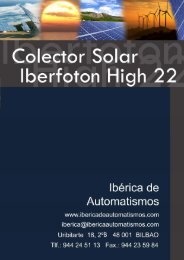
<strong>Laser</strong>-<strong>Distance</strong>-<strong>Sensor</strong><br />
<strong>Laser</strong>-Triangulation with<br />
CMOS-Technology<br />
Basic features:<br />
Center distance<br />
25 - 160 mm<br />
Resolution typ. 0.6-40 µm *<br />
Analogue output 4- 20 mA<br />
optional: 1-5 VDC with integrated<br />
shunt in connection cable<br />
RS232 interface<br />
High linearity<br />
Colour insensitive<br />
measurement<br />
<strong>Laser</strong> Class 2<br />
Protection IP 67<br />
¢<br />
(* <strong>de</strong>pends on version)<br />
Typical applications:<br />
<strong>Distance</strong> measurement<br />
Thickness measurement<br />
Displacement measuring<br />
Profile checking<br />
Out-of-balance measurement<br />
Control of overlapping<br />
Position control<br />
Cone belt measurement<br />
Stroke, oscillation<br />
Advantages:<br />
Small dimensions<br />
High resolution<br />
High linearity<br />
Wi<strong>de</strong> dynamic range<br />
High insensitive to colour<br />
due to CMOS-Technology and<br />
intern. digital signal processor<br />
with intelligent logic<br />
Vibration resistance 15 g/<br />
(10 Hz - 1 kHz)<br />
Measuring range<br />
Resolution<br />
Outputs<br />
Sampling rate<br />
Small dimensions<br />
Dimensions<br />
Mounting<br />
holes<br />
2x Ø 4,3 / 5,8<br />
<strong>Laser</strong>beam<br />
65<br />
16<br />
Wiring connections<br />
2<br />
3<br />
1<br />
4<br />
7<br />
5<br />
7 pin plug<br />
rear sight<br />
Description<br />
6<br />
57<br />
4<br />
Series LDS 70/232<br />
5<br />
5-200 mm (7 versions)<br />
0.6-40 µm*<br />
4-20 mA / 1-5 VDC / RS232<br />
1000 Hz<br />
(65 x 50 x 20) mm<br />
50<br />
40<br />
LDS 70<br />
LASERSTRAHLUNG<br />
NICHT IN DEN STRAHL BLICKEN<br />
LASERKLASSE 2<br />
P 1 mW; = 670 nm<br />
nach DIN EN 60825-1 03.97<br />
20<br />
All dimensions in mm<br />
Pin Colour Reference<br />
1 gn Error output, open collector<br />
NPN; switching to GND,<br />
Uce max. 30 VDC,<br />
100 mA, short circuit protected<br />
2 ye <strong>Laser</strong> ON/OFF<br />
connect pin 2+6 => <strong>Laser</strong> ON<br />
3 bl Rx 232<br />
4 pink Tx 232<br />
5 gr Output 4-20 mA,<br />
short circuit protected<br />
6 bn GND<br />
7 wt Supply 12-30 VDC<br />
inverse polarity protected<br />
--- Shield (PE)<br />
The <strong>Laser</strong> Triangulation <strong>Sensor</strong> LDS 70 is based on latest CMOS<br />
technology. It is working with a visible red laser.<br />
The measuring values are linearised by an internal signal<br />
processor. Due to this the sensor measures the distance very<br />
accurate and in<strong>de</strong>pen<strong>de</strong>nt from colour of surface. The LDS 70<br />
provi<strong>de</strong>s an analogue output with 4-20 mA. Optional there is a<br />
connection cable with shunt for 1-5 VDC output available.The<br />
RS232 interface is inclu<strong>de</strong>d.
Technical data<br />
Electrical data<br />
Light source<br />
Data on ambience<br />
conditions<br />
Or<strong>de</strong>ring information<br />
Supply voltage<br />
12-30 VDC, typ. 24 VDC, 150 mA<br />
Frequency<br />
1 kHz<br />
Analogue output<br />
4-20 mA<br />
(option: 1-5 VDC)<br />
Wavelength<br />
typ. 670 nm, visible/red<br />
Power<br />
< 1 mW<br />
<strong>Laser</strong> Class 2 DIN (EN 60825-1:11.01)<br />
max. operating temp.<br />
0 to +55 °C (+32 to +130 °F)<br />
max. storage temp.<br />
-20 to + 70 °C (-4 to +158 °F)<br />
Protection class IP 67<br />
EMC EN 50081-1 , EN 61000-6-2<br />
Specifical data <strong>Sensor</strong> LDS 70/...<br />
5 10 20 50 100 200**<br />
Measuring range 5 mm 10 mm 20 mm 50 mm 100 mm 200 mm<br />
Center distance 22.5 mm 25 mm 40 mm 70 mm 100 mm 160 mm<br />
Linearity typ.<br />
+/- 5 µm +/- 10 µm +/- 20 µm +/- 50 µm +/- 100 µm +/- 400 µm<br />
Resolution*stat.(typ.) 0.6µm 1µm 2µm 5µm 20µm 40µm<br />
dyn. at 1 kHz 3 µm 5 µm 10 µm 25 µm 100 µm 200 µm<br />
Meas. area Ø typ. ~0.5 mm ~0.8 mm ~0.3 mm ~0.1 mm ~0.1 mm ~2 mm<br />
at center distance<br />
Temp. stability<br />
0.03 % of measuring range / °C<br />
0.08 % o.m.r. / °C<br />
* All values at white, diffuse reflecting surfaces (AL2O3- ceramic) as reference<br />
LDS70/232 5 10 20 50 100 200<br />
Part No. 10652789 10652849 10652841 10652850 10652848 10652635<br />
plug connector inclu<strong>de</strong>d<br />
** 250 mm measuring range available, see datasheet LDS 70/250-F, RS232 see user manual<br />
Cable length:3 m, plug M12, 7-pin, output 4-20 mA and RS232 (6 m optional) 11242835<br />
Cable length:3 m, plug M12, 7-pin, output 1-5 VDCand RS232 (6 m optional) 11242836<br />
Cable length:3 m, plug M12, 7-pin, output 4-20 mA, 9pin Sub-D RS232 connector 11242790<br />
ELT/LDS/LDS70-232E7<br />
Displacement measuring<br />
Contour, thickness and<br />
profile measurement<br />
LDS 70<br />
Oscillation,<br />
Out-of balance measurement<br />
<strong>Distance</strong>/profile measurement<br />
Presented by:<br />
LASER CLASS 2<br />
DIN EN 60825-1: 11.01<br />
<strong>Laser</strong> radiation<br />
Avoid exposure to beam<br />
<strong>Sensor</strong>s of CLASS 2 don’t need<br />
environment with special protection<br />
© Eltrotec 07/06 (we reserve the right to make changes in the interest of technical progress)
ELTROTEC<br />
<strong>Sensor</strong> GmbH<br />
Heinkelstrasse 2<br />
D-73066 Uhingen<br />
Telefon: 07161 / 98872-300<br />
Telefax: 07161 / 98872-303<br />
Internet:www.Eltrotec.com<br />
e-mail: Info@Eltrotec.com<br />
<strong>Laser</strong>-<strong>Distance</strong>-<strong>Sensor</strong><br />
Series LDS 70/250-F<br />
Measuring range 250 mm<br />
Resolution<br />
³ 50 µm<br />
Measuring frequency 1000 Hz<br />
Small dimensions (65 x 50 x 20) mm<br />
High shock resistance ~ 20g<br />
Principal features:<br />
Measuring distance<br />
100 - 350 mm<br />
Resolution typ. ³ 50 µm<br />
Analogue output 4- 20 mA<br />
optional: 1-5 VDC with integrated<br />
shunt in connection cable<br />
RS232 optional<br />
High linearity<br />
<strong>Laser</strong> Class 2<br />
Protection IP 67<br />
¢<br />
Typical applications:<br />
Dimensions<br />
Mounting<br />
holes<br />
2x Ø 4,3 / 5,8<br />
<strong>Laser</strong>beam<br />
65<br />
16<br />
57<br />
4<br />
Wiring connections<br />
Pin<br />
5<br />
50<br />
40<br />
LDS 70/250-F<br />
LASERSTRAHLUNG<br />
NICHT IN DEN STRAHL BLICKEN<br />
LASERKLASSE 2<br />
P 1 mW; = 670 nm<br />
nach DIN EN 60825-1 03.97<br />
Colour Reference<br />
20<br />
All dimensions in mm<br />
<strong>Distance</strong> measurement to road or rail<br />
Advantages:<br />
Small dimensions<br />
High resolution<br />
High linearity<br />
Wi<strong>de</strong> dynamic range<br />
Insensitive to colour and<br />
surface due to special<br />
interference optic<br />
Vibration resistance 20g<br />
Extremely resistance sensor<br />
for online distance measurement<br />
“car to road” or<br />
“train to rail”<br />
2<br />
1<br />
3<br />
5 pin plug<br />
rear sight<br />
Description<br />
5<br />
4<br />
1 gn Error output, open collector<br />
NPN; switching to GND,<br />
Uce max. 30 VDC,<br />
100 mA, short circuit protected<br />
2 ge <strong>Laser</strong> ON/OFF<br />
connect pin 2+ 4 => <strong>Laser</strong> ON<br />
3 gr Output 4-20 mA,<br />
short circuit protected<br />
4 bn GND<br />
Potential for (2) and U b (5)<br />
5 ws Supply 11-30 VDC<br />
inverse polarity protected<br />
--- Shield (PE)<br />
The <strong>Laser</strong>triangulation <strong>Sensor</strong> LDS 70 is based on latest CCDtechnology.<br />
It is working with a visible red laser.<br />
The measuring values are linearised by a internal signal processor.<br />
Due to this the sensor measures the distance very accurate and<br />
in<strong>de</strong>pen<strong>de</strong>nt from colour of surface. The LDS 70/250-F provi<strong>de</strong>s an<br />
analogue output with 4-20 mA. Optional there is a connection cable<br />
with shunt for 1-5 VDC output available.<br />
Special application is, to measure distance car body to road or train<br />
body to rail.
Technical data<br />
Electrical data<br />
Light source<br />
Data on ambiente<br />
conditions<br />
Measuring<br />
Resolution<br />
Measuring area<br />
Temperature<br />
Or<strong>de</strong>ring information<br />
Supply voltage<br />
11-30 VDC, typ. 24 VDC, 150 mA<br />
Frequency<br />
1000 Hz<br />
Analogue output<br />
4-20 mA<br />
(option: 1-5 VDC/ 2-10 VDC with shunt)<br />
Wavelength<br />
typ. 670 nm, visible/red<br />
Power<br />
< 1 mW (IEC standard)<br />
<strong>Laser</strong> Class 2 DIN (EN 60825-1:03.97)<br />
max. operating temp. 0 to +55 °C<br />
max. storage temp. -20 to +70 °C<br />
Protection IP 67<br />
max. permis. daylight<br />
ELTROTEC<strong>Sensor</strong>GmbH<br />
Heinkelstr.2<br />
D-73066Uhingen<br />
www.eltrotec.com<br />
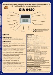
Series LDS 85/<br />
Measurement Range [mm]:<br />
2<br />
10<br />
20<br />
50<br />
100<br />
200<br />
250<br />
500<br />
750<br />
C<br />
Highestresolution in class<br />
Highestrepeatabilityin class<br />
Highestaccuracy in class<br />
Bestperformance/price ratioin class<br />
Intelligent laseroptical<br />
displacement measurement<br />
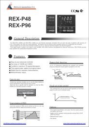
<strong>Laser</strong> <strong>Distance</strong> <strong>Sensor</strong><br />
LDS 85
Series LDS 85<br />
Compact laser displacement sensors<br />
SeriesLDS85isanlaseropticaldisplacementmeasurement<br />
system with extensive functional features. Through the<br />
integral controller the system can be completelyconfigured<br />
via the supplied PC software and also offers extensive<br />
functions such as limit switches, averaging, adjustable<br />
measurement ratesand the synchronizationoftwosensors,<br />
e.g. for thickness measurement. With the unique Real-Time<br />
Surface Compensation (RTSC) the system facilitates<br />
measurements against awi<strong>de</strong> range of material surfaces<br />
(e.g. bare metals, black rubber or shiny painted surfaces).<br />
Due to the large selection of different measurement ranges<br />
from 2 to 750 mm there is a perfect sensor for each<br />
application. The compact <strong>de</strong>sign makes the series LDS 85<br />
sensors particularly suitable for industrial applications in<br />
automatedmachineryandproductionequipment.<br />
The series LDS 85 operates according to the triangulation<br />
principle.Alaserdio<strong>de</strong>projectsavisiblespotoflightontothe<br />
target surface. The light reflected from this spot is directed<br />
throughanopticalreceivingsystemontoaposition-sensitive<br />
element(CCDarray).Ifthetargetchangesitsdistancetothe<br />
sensor,this leads to achange of the imaging spot on the<br />
CCDarray.Thepositionofthespotinci<strong>de</strong>ntontheCCDarray<br />
isevaluated.<br />
ADVANTAGES<br />
• RTSC fast adaptation to changing surfaces<br />
• Compact <strong>de</strong>sign with integral electronics<br />
•Configuration and control via software PC<br />
• Synchronization of two sensors mandatory<br />
for differential and thickness measurement<br />
• Analog and digital outputs<br />
•Programable limits<br />
Performanceproof<br />
Every sensor is calibrated according to ISO<br />
9000 quality standards and an individual<br />
calibration protocol is inclu<strong>de</strong>d with every<br />
sensor.<br />
Compact<strong>de</strong>signwithintegralcontroller<br />
Despite its compact dimensions, the LDS 85 series has a<br />
completely integrated controller. There is no separate<br />
controllerhousingwhichmeansthatinstallationandwiringis<br />
carriedouteasilyandquickly.Itssmallsizeallowsthesensor<br />
tobeintegratedintotightinstallationspaces.<br />
The measurements are processed digitally in the integral<br />
controller.The data are output either analog or digitally via<br />
RS422 (optionally with USB - cable EL-PC85-3/USB<br />
required).<br />
CCD-array<br />
with RTSC<br />
multi-lens<br />
optics<br />
filter<br />
optics<br />
laserdio<strong>de</strong><br />
LASER RADIATION<br />
Do not stare into the beam<br />
CLASS 2LASER PRODUCT<br />
IEC 60825-1: 2001-11<br />
P
Typical applications<br />
Contourmeasurementoncatalyticconverters<br />
During the production of ceramic billets for car catalytic<br />
converters, the billets are measured for roundness and<br />
diameteronanumberofradialtracksforclassification.Using<br />
the IF2004 interface card (page 6),<br />
the enco<strong>de</strong>r and sensor signalsare<br />
synchronized to obtain precise<br />
correspon<strong>de</strong>nce in angle and<br />
shape.<br />
Partsmeasurement<br />
On machined surfaces of metal products,<br />
the LDS 85 is employed for quality<br />
assurance.Quantitiessuchasroundness,<br />
concentricity, eccentricity and bending<br />
<strong>de</strong>flectionare<strong>de</strong>termined.<br />
Synchronousthicknessmeasurement<br />
Thethicknessofthevariouswebmaterials<br />
can be reliably acquired with LDS 85<br />
sensors. With their high measuring rate<br />
andthepossibilityofsynchronizingtwoor<br />
more sensors (simultaneous<br />
measurement), the sensors are i<strong>de</strong>al for<br />
movingandoscillatingtargets.<br />
FlatnessmeasurementofICpins<br />
Toachievethebestqualityduringboardassembly,allICpins<br />
mustlie inone plane. Inmo<strong>de</strong>rn<br />
automatic placement systems<br />
the ICs are therefore measured<br />
directly before placement. The<br />
tiny light spot diameters enable<br />
the measurement of the finest<br />
pingeometries.<br />
Shapeconformanceon<br />
aluminumwheels<br />
After casting, aluminum wheels<br />
are measured for a range of<br />
features, e.g. hub <strong>de</strong>pth, roundness,<br />
bulging, etc., before being<br />
processedfurther.<br />
Surfaceprofiling<br />
Due to the small measuring spot and<br />
RTSC(Real-TimeSurfaceCompensation),<br />
the LDS 85 is excellent for the high<br />
precision mapping of any target<br />
regardless of its reflectivity, angle, shape<br />
andcolor.<br />
Partpositioninginproductionlines<br />
Forautomatedprocessing stagesoncarbodiesorvehicles<br />
an exact <strong>de</strong>termination of the<br />
position relative to the<br />
processing tool is necessary<br />
(drilling, punching, fitting subassemblies).<br />
Due to the<br />
adjustable exposure time and<br />
the real-time surface<br />
compensation, the series LDS<br />
85 is particularly suitable for the<br />
highprecisionacquisitionofhighlyglossysur-faces.<br />
<strong>Distance</strong>ofvehicletoroadsurface<br />
In road tests pitching and rolling movements, spring<br />
compression during braking and other quantities are<br />
measured with LDS 85 sensors. The series LDS 85 is<br />
particularly suitable here due to<br />
the compact construction and<br />
the possibility of supplying the<br />
sensor from the vehicle power<br />
supply(11...30VDC).Forthese<br />
applications there are special<br />
mo<strong>de</strong>ls LDS 85-250 VT available<br />
with increased tolerance to<br />
extra-neouslightandvibration.<br />
03
Series LDS 85<br />
Compact laser displacement sensors<br />
RTSC:Real-TimeSurfaceCompensation<br />
WithRTSC,aworld-wi<strong>de</strong>uniqueinnovation,the<strong>de</strong>greeof<br />
reflection from the target is compensated during the ongoingexposureandinreal-time.Theexposuretimeorthe<br />
amountoflightproducedbythelaserisoptimallymatched<br />
to the currentlyrunning exposure cycle. It is only sensors<br />
from ELTROTEC which are equipped with this innovative<br />
real-time control and consequently they always achieve<br />
optimumresultsevenwithchangingsurfaces.<br />
Adjustableexposuretime/measurementrate<br />
Fortargetswithlittlediffusereflectivitytheexposuretimecan<br />
be adjusted. The programed measurement cycle remains<br />
always constant, therefore the real-time data rate is<br />
guaranteed.<br />
Adjustableexposuretime/measurementrate<br />
Measuring rate 2.5kHz 1.25kHz 625 Hz 312.5Hz<br />
Max.exposuretime 0.4ms 0.8 ms 1.6ms 3.2ms<br />
Standard commercially available laser triangulation<br />
sensorsoperatewithatime-shift controlwhichisadditive<br />
to the measurement cycles already conclu<strong>de</strong>d. In this<br />
casethe<strong>de</strong>greeofreflectionfromthelastmeasurementis<br />
used to <strong>de</strong>rive the <strong>de</strong>gree of reflection for the next<br />
measurement. With changing or structured surfaces the<br />
measurement results therefore <strong>de</strong>viate noticeably from<br />
the actual measurement quantity,whereas the LDS 85 is<br />
controlledinrealtimeattherespectiveoptimumoperating<br />
point.<br />
Configurationviasoftware<br />
Besi<strong>de</strong>susingthesensorkeys,theconfigurationcanalsobe<br />
carriedoutconvenientlyviathePC.Thesoftwarerequiredfor<br />
thisisinclu<strong>de</strong>dinthesupplieditems.<br />
Configurablevia software<br />
RS422 or USB(option)<br />
Principle<br />
RTSCReal-TimeSurface Compensation<br />
compared totime-shift control.<br />
Adjustablelimitswitches<br />
Foraprecisemeasurement,theLDS85 sensorscanalsobe<br />
programed for tolerance or limit monitoring. Two switching<br />
pointsareavailablewhichcanbeadjustedviathesoftware.A<br />
hysteresisforeachlimitcanbeprogramed.<br />
y(mm)<br />
correct measurement<br />
y(mm)<br />
measurement error<br />
LDS85<br />
withRTSCreal-time<br />
surface compensation<br />
t<br />
Standardlasersensorswith<br />
time-shift control give<br />
distinctlyincorrectsignals<br />
withachange of surface<br />
t<br />
04
Features<br />
SynchronousdatarecordingwiththeIF2004<br />
With the IF2004 PCI interface card, which is available as an<br />
accessory, the data from up to four sensors can be<br />
synchronously read via aFIFO memory.Readings from an<br />
enco<strong>de</strong>rorlinearmeasurementsystemasthefourthchannel<br />
canbeusedtomapuptothreeLDS85sensors.<br />
Synchronous data recording withtheIF2004<br />
interfacecard<br />
IF2004<br />
enco<strong>de</strong>r<br />
upto 4sensors<br />
Synchronizationoftwosensors<br />
Simultaneousmeasurementusingtwosensorsisnecessary<br />
inor<strong>de</strong>rtoobtainpreciseresults,withthicknessordifferential<br />
measurements,whenthetargetismovingoroscillating.The<br />
LDS85seriessupportsthisfunction,whereonesensoracts<br />
as the master and provi<strong>de</strong>s the clock for the slave.<br />
Consequently, the measurements are always synchronous<br />
andthereforesupplyexactmeasurementresults.<br />
Synchronization oftwo sensors<br />
sensor 1 sensor 1<br />
t d<br />
Highflexcablesratedformovingcabletracks<br />
The type EL-PC 85-xx cables are rated for operation in<br />
movingcabletrackswithaminimumcablebendingradiusof<br />
80mm.<br />
Analoganddigitaloutputs<br />
Withtwoanalogueoutputsignals0...10Vand4...20mAas<br />
well as the serial RS422 interface, the LDS 85 range of<br />
sensorsfulfilsallinterfacerequirements.Thebaudrateofthe<br />
RS422 can be set in standard steps from 9,600 to 115,200<br />
baud. This allows adirect communication to aPLC or any<br />
other host. In addition the dataformat of the serial interface<br />
canbechangedfrombinarytoASCIIcharacteroutput.<br />
Wi<strong>de</strong>inputrange(11...30VDC)<br />
The 11 ... 30 VDC supply also enables operation in 12 V<br />
networks or direct supply from a car's on-board power<br />
supply.<br />
real<br />
thickness<br />
LDS85 with<br />
simultaneoussynchronization<br />
sensor 2 sensor 2<br />
t<br />
error<br />
Commonsensorwith<br />
typicalmeasurement<strong>de</strong>lay<br />
t<br />
Adjustablefilterfunctions<br />
Toachieve the best results for each application,<br />
three different filter functions can be applied to the<br />
measurementresults.<br />
The recursive mean works similar to an analog<br />
low-passfilter.<br />
The moving average enables ahigh dynamic<br />
responseevenwithfiltering.<br />
The median filter is especially suitable for<br />
surfaceswithrandomfalsereadings.<br />
Allfiltersettingsdonotreducetheoutput frequency<br />
(datarate)oftheanaloganddigitaloutputs.<br />
3.5<br />
3<br />
2.5<br />
2<br />
1.5<br />
1<br />
0.5<br />
0<br />
3.5<br />
3<br />
2.5<br />
2<br />
1.5<br />
1<br />
0.,5<br />
oszillation(original)<br />
200<br />
400 600<br />
positionsignal<br />
800<br />
oszillation<br />
moving average (N =128)<br />
1000<br />
8.5<br />
0 200 400 600 800 1000 0 200 400 600 800 1000<br />
positionsignal<br />
positionsignal<br />
11<br />
10.5<br />
10<br />
9.5<br />
9<br />
8.5<br />
0<br />
11<br />
10.5<br />
10<br />
9.5<br />
9<br />
200<br />
profile (original)<br />
400 600<br />
positionsignal<br />
profile<br />
median(N =9)<br />
800<br />
1000<br />
05
Series LDS 85<br />
Software and interface card<br />
sensorCONFIGconfiguration/DAQsoftware<br />
sensorCONFIGisthesoftwareinclu<strong>de</strong>dinthesupplieditems<br />
for easy sensor configuration. All the settings can be<br />
implemented conveniently via aWindows user interface on<br />
thePC.Thesensorparametersaresenttothesensorviathe<br />
serialportandcanalsobesavedifrequired.<br />
IF 2004 PCI card<br />
The IF2004 interface card enables the synchronous<br />
acquisition of manysensor signalsand an enco<strong>de</strong>r.The<br />
dataare saved inaFIFOmemoryto facilitate resourcesaving<br />
block-by-block processing inthe PC.<br />
sensorCONFIG also inclu<strong>de</strong>s aeasy to use DAQ module<br />
whichcandisplayandsavemeasurementresults.Thelinkto<br />
the PC is ma<strong>de</strong> via the EL-PC 85-3/USB sensor cable<br />
(optional). All the connections are then realized using timesavingplugconnectors.<br />
Driversupportforcustomersoftware<br />
FortheLDS85sensorsadocumenteddriverDLLisavailable<br />
freeofchargewhichenableseasyintegrationofthesensors<br />
intoexistingsoftware.<br />
Features<br />
-4-channel version (foursensor inputs)<br />
-Enco<strong>de</strong>r input<br />
-Gate input<br />
-FIFO memory of 2kByte for each channel, which<br />
increases when all channels are occupied<br />
-Incremental enco<strong>de</strong>rinput, optically<strong>de</strong>coupled,<br />
nominally5V(min. 3V)<br />
Technical data IF2004<br />
Programingofthesensor<br />
select<br />
zero<br />
output<br />
speed<br />
avg<br />
zero<br />
state<br />
<strong>de</strong>fault<br />
>5s<br />
function<br />
enter<br />
All important functions can be set directly on the<br />
sensorusingthetouchkeys.<br />
Bus<br />
Interface<br />
FIFO<br />
Input<br />
Input<br />
Software<br />
sensors<br />
32 bit PCI /33 MHz /5VDC
Technical data<br />
Mo<strong>de</strong>l<br />
LDS 85/2 LDS 85/10 LDS 85/20 LDS 85/50<br />
LDS<br />
85/100<br />
LDS<br />
85/200<br />
LDS<br />
85/500<br />
LDS<br />
85/750<br />
Measuringrange 2mm 10 mm 20 mm 50 mm 100 mm 200 mm 500 mm 750 mm<br />
Start measuringrange 24 mm 30 mm 40 mm 45 mm 70 mm 70 mm 200 mm 200 mm<br />
Midrange 25 mm 35 mm 50 mm 70 mm 120 mm 170 mm 450 mm 575 mm<br />
Endmeasuringrange 26 mm 40 mm 60 mm 95 mm 170 mm 270 mm 700 mm 950 mm<br />
Linearity<br />
Resolution (at 2.5 kHz<br />
without averaging)<br />
Measuringrate<br />
Light source<br />
Permissable ambient light<br />
<strong>Laser</strong>safety class<br />
Spot diameter<br />
Operatingtemperature<br />
Storage temperature<br />
Output<br />
Switch Input<br />
Operation<br />
Powersupply<br />
<strong>Sensor</strong> cable length<br />
Synchronization<br />
measurements<br />
switchingoutputs<br />
Electromagnetic compatibility<br />
Protection class<br />
Vibration<br />
Shock<br />
Weight (with 0.25 cm cable)<br />
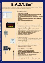
Dimensions /Course of beam dimensions in mm, not to scale<br />
Dimensions LDS85/2-LDS85/<br />
200<br />
Course ofbeamLDS85/2-LDS85/200<br />
3xmounting<br />
holes ø4.5<br />
A<br />
B<br />
<strong>Laser</strong> beam<br />
80<br />
89<br />
97<br />
13.4<br />
ø4<br />
13.4<br />
startof measuring<br />
range (SMR)<br />
15<br />
ø8<br />
24.2 36.1<br />
Dimensions LDS85/ 500 / LDS85/ 750mm<br />
75<br />
end of measuring<br />
range (EMR)<br />
Course ofbeamLDS85/500/LDS85/750mm<br />
mounting<br />
holes<br />
3xø4.5<br />
101<br />
85<br />
130<br />
140<br />
150<br />
laser beam<br />
15<br />
ø5<br />
15<br />
(SMR)<br />
17.5<br />
12<br />
Cable connector<br />
sensor<br />
31<br />
75<br />
~50<br />
(EMR)<br />
MR SMR a j e A B<br />
2 24 35° 40° 44.8° 25.8 16.8<br />
10 30 34.3° 35.2° 35.6° 28.7 20.5<br />
20 40 28,8° 27.5° 26.7° 30.1 22<br />
50 45 26.5° 23.0° 18.3° 31.5 22.5<br />
100 70 19.0° 15.4° 10.9° 32.6 24.1<br />
200 70 19.0° 9.78° 6.97° 33.1 24.1<br />
500 200 19.3° 9.8° 7.0° - -<br />
750 200 19.3° 7.7° 5.0° - -<br />
ELTROTEC <strong>Sensor</strong> GmbH<br />
Heinkelstr.2<br />
73066 Uhingen<br />
Tel.: +49 7161 /98872-300<br />
Fax: +49 7161 /98872-303<br />
info@<br />
eltrotec.com<br />
www.eltrotec.com<br />
certified DIN EN ISO 9001 :2000<br />
modifications reserved /Eltrotec 02/07