REX-P48 REX-P96 - Iberica de Automatismos
REX-P48 REX-P96 - Iberica de Automatismos
REX-P48 REX-P96 - Iberica de Automatismos

You also want an ePaper? Increase the reach of your titles
YUMPU automatically turns print PDFs into web optimized ePapers that Google loves.
R<br />
R<br />
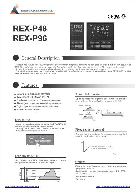
<strong>REX</strong>-<strong>P48</strong><br />
<strong>REX</strong>-<strong>P96</strong><br />
General Description<br />
The <strong>REX</strong>-<strong>P48</strong> (1/8DIN) and <strong>REX</strong>-<strong>P96</strong> (1/4DIN) are user-friendly ramp/soak controllers that can store two sets of patterns with accuracy of<br />
0.3%. Each pattern can have up to eight segments. Two patterns can be linked so that a program with up to 16 segments can be stored.<br />
Optional digital input as well as key operation enables you to run, stop and hold the program, and skip the segment.<br />
Time signal output or pattern end output is also available. With these functions accompanied by external instruments, <strong>REX</strong>-<strong>P48</strong>/96 provi<strong>de</strong>s<br />
easy operation for complicated temperature control.<br />
Features<br />
Easy-to-use ramp/soak controller<br />
Two sizes of 1/4DIN and 1/8DIN<br />
2 patterns, maximum 16 segments/program<br />
Time signal output, pattern end signal output<br />
Digital input for operation mo<strong>de</strong> selection<br />
Retransmission output<br />
Pattern link function<br />
Up to 16 ramp/soak segments per program are available<br />
simply by linking the second pattern (program) to the first.<br />
Temp<br />
Pattern No.1<br />
Temp<br />
Linked pattern<br />
Easy-to-use<br />
Temp<br />
Pattern No.2<br />
Simple key operation enables you to use the <strong>REX</strong>-<strong>P48</strong>/96 for<br />
various applications where easy-to-use is critical.<br />
Each key has a specific role for operation so that the <strong>REX</strong>-<br />
<strong>P48</strong>/96 can eliminate operator's mistake.<br />
Fixed set point control<br />
RESET RUN LEVEL<br />
/TIME<br />
END<br />
Time<br />
Time<br />
The unlimited time can be set for soak segments so that fixed<br />
setpoint control can be obtained easily.<br />
PTN1/<br />
PTN2<br />
SET<br />
HOLD STEP Temp<br />
RKC <strong>REX</strong>-<strong>P96</strong><br />
Infinite time segment<br />
(Fixed set point control)<br />
Four groups of PID<br />
Time<br />
Up to four groups of PIDs can be stored so that you can use<br />
appropriate PIDs for different temperature ranges.<br />
Range<br />
Level 4<br />
Level 3<br />
Level 2<br />
Level 1<br />
Time<br />
Options<br />
• Time signal output/Pattern end output: Two time signal outputs<br />
per pattern can be set.<br />
• Digital input for operation mo<strong>de</strong> selection among RUN, STOP,<br />
STEP and HOLD<br />
• Retransmission output<br />
• Two alarms<br />
info@iberica<strong>de</strong>automatismos.com<br />
www.iberica<strong>de</strong>automatismos.com
Input<br />
Specifications<br />
Input<br />
a) Thermocouple : K, J, R, S, B, E, T, N (JIS/IEC), PLII (NBS)<br />
W5Re/W26Re (ASTM), U, L (DIN)<br />
Influence of external resistance : Approx. 0.35μV/Ω<br />
Input break action : Up-scale<br />
b) RTD : Pt100 (JIS/IEC), JPt100 (JIS)<br />
Influence of input lead resistance : Approx. 0.0075%/Ω of reading<br />
• Maximum 10Ω per wire<br />
Input break action : Up-scale<br />
Sampling time<br />
0.5 sec<br />
PV bias<br />
-1999 (-199.9) to 9999 (999.9)°C [°F]<br />
PV ratio<br />
0.001 to 9.999<br />
Performance<br />
Measuring accuracy<br />
± (0.3% of span + 1 digit)<br />
Cold junction temperature error<br />
Within ±1.5°C (between 0 and 50°C [32 and 122°F])<br />
• Accuracy is not guaranteed between 0 and 400°C (0 and 752°F) for<br />
type B input.<br />
•Accuracy is not guaranteed between 0 and 32°F for Type N, PLII and<br />
W5Re/W26Re.<br />
Segment time accuracy<br />
Within ±0.02% of reading<br />
Other setting<br />
Within ±0.5% of span<br />
Insulation resistance<br />
More than 20MΩ (500V DC) between measured terminals and ground<br />
More than 20MΩ (500V DC) between power terminals and ground<br />
Dielectric strength<br />
1000V AC for one minute between measured terminals and ground<br />
1500V AC for one minute between power terminals and ground<br />
Program<br />
Storage program pattern : Max. 2 patterns (8 segments per pattern)<br />
Storage segments : Max. 16 segments<br />
(Possible to link, 8 segments x 2 patterns)<br />
Program repeat : 1 - 999 times or continuous<br />
Level setting :<br />
See input range<br />
Time setting :<br />
00 hr 00 min to 99 hrs 59 min<br />
PID constant section : 4 levels (For level PID control)<br />
Start mo<strong>de</strong> :<br />
Zero start or PV start (selectable)<br />
Wait zone :<br />
Up, down 0 to 99°C (°F) or 0.0 to 9.9°C (°F) at<br />
going up or down<br />
Control<br />
Control method<br />
a) PID control with autotuning<br />
b) Heat/cool PID control with autotuning<br />
Major setting range<br />
Setting range :<br />
Same as input range.<br />
Heat si<strong>de</strong> proportional band : 1(0.1) to setting range<br />
(ON/OFF action when P=0)<br />
Cool si<strong>de</strong> proportional band 1 to 1000% of heat si<strong>de</strong> proportional band<br />
Integral time :<br />
1 to 3600sec.(P + D action when I=0)<br />
Derivative time :<br />
1 to 3600sec.(P + I action when D=0)<br />
Differential gap :<br />
0 to 100°C (°F) or 0.0 to100.0°C (°F)<br />
(When used with ON/OFF action)<br />
Output limiter high : -5.0 to +105.0%<br />
Output limiter low : -5.0 to +105.0%<br />
Control output<br />
Relay output :<br />
Form C contact, 250V AC 3A (resistive load)<br />
Voltage pulse output : 0/12V DC<br />
(Load resistance : More than 600Ω)<br />
Current output :<br />
0 to 20mA or 4 to 20mA DC<br />
(Load resistance : Less than 600Ω)<br />
Alarm<br />
Temperature alarm (Optional)<br />
a) Number of alarm : 2 points<br />
b) Alarm action<br />
Deviation high, low, high/low, band, and process high, low alarms<br />
Set value high, low (In contrast to the process high or low alarm,<br />
the set value high or low alarm is activated when the programmed<br />
set value goes over or un<strong>de</strong>r a preset value.)<br />
c) Alarm differential gap : 0 to 10°C (°F) or 0.0 to 10.0°C (°F)<br />
• Hold function and re-hold function can be ad<strong>de</strong>d to <strong>de</strong>viation high<br />
low and high/low.<br />
• Energized/<strong>de</strong>-energized alarm (selectable)<br />
Alarm output<br />
Relay output, Form A contact 250V AC 1A (resistive load)<br />
Options<br />
External contact input<br />
Type :<br />
RESET, RUN, HOLD, STEP<br />
Input method : Non voltage contact input<br />
OPEN : 500kΩ or more<br />
CLOSE : 10Ω or less<br />
Time signal output<br />
Setting range : 00 hr 00 min to 99 hr. 59 min<br />
Storage pattern : 2 times/pattern<br />
Output :<br />
1 point<br />
Relay contact output, 250V AC 1A (resistive load)<br />
• When "Pattern end output" is selected, "Time signal output " is not available.<br />
Pattern end output<br />
Setting range : 00 hr 00 min to 99 hr. 59 min<br />
Output :<br />
1 point<br />
Relay contact output, 250V AC 1A (resistive load)<br />
• When "Time signal output" is selected, "Pattern end output " is not available.<br />
Retransmission output<br />
Number of outputs : 1 point<br />
Output signal : 0 to 10mV, 0 to 100mV DC<br />
(Load resistance : More than 20kΩ)<br />
0 to 1V, 0 to 5V, 0 to 10V, 1 to 5V DC<br />
(Load resistance : More than 1kΩ)<br />
0 to 20mA, 4 to 20mA DC<br />
(Load resistance : Less than 600Ω)<br />
Output type : Measured value (PV), Set value (SV), Manipulated<br />
output value (MV)<br />
General specifications<br />
External Dimensions (W x H x D)<br />
<strong>P48</strong> : 48 x 96 x 100mm<br />
<strong>P96</strong> : 96 x 96 x 100mm<br />
Supply voltage<br />
90 to 264V AC (Including power supply voltage variation)<br />
[Rating : 100 to 240V AC] (50/60Hz common)<br />
Power consumption<br />
Less than 9VA (100 to 240V AC)<br />
Effect by power failure<br />
A power failure of 20ms or less will not affected the control action.<br />
If the power failure is shorter than 2 seconds, the autotuning function<br />
(if used) will be canceled but the program continues. If the power<br />
failure is longer than 4 seconds, the controller returns to its initial<br />
status (start mo<strong>de</strong>).<br />
Operating environments : 0 to 50°C [32 to 122°F] , 45 to 85% RH<br />
Memory backup : RAM back-up by lithium battery<br />
Net weight<br />
<strong>P48</strong>A: pprox. 300g<br />
<strong>P96</strong>A: pprox. 400g<br />
info@iberica<strong>de</strong>automatismos.com<br />
www.iberica<strong>de</strong>automatismos.com
Mo<strong>de</strong>l and Suffix Co<strong>de</strong><br />
Specifications<br />
Mo<strong>de</strong>l and Suffix Co<strong>de</strong><br />
<strong>REX</strong>-<strong>P48</strong><br />
Mo<strong>de</strong>l<br />
<strong>REX</strong>-<strong>P96</strong><br />
PID reverse control with AT<br />
F<br />
PID direct control with AT<br />
D<br />
Control method<br />
Level PID reverse control with AT<br />
L<br />
Level PID direct control with AT<br />
M<br />
Heat/cool PID control<br />
W<br />
Heat/cool level PID control<br />
V<br />
Input type<br />
See input range co<strong>de</strong> table<br />
Scale range<br />
See input range co<strong>de</strong> table<br />
Relay output<br />
Control output (OUT1)<br />
Voltage pulse<br />
DC current : 0 to 20mA<br />
DC current : 4 to 20mA<br />
Control action : F, D, L, M<br />
Relay output<br />
Control output (OUT2) Voltage pulse<br />
DC current : 0 to 20mA<br />
DC current : 4 to 20mA<br />
No alarm<br />
Alarm 1<br />
See alarm co<strong>de</strong> table<br />
No alarm<br />
Alarm 2<br />
See alarm co<strong>de</strong> table<br />
Not supplied<br />
Contact input<br />
Supplied<br />
Not supplied<br />
Output function<br />
Pattern end output<br />
Time signal output<br />
Not supplied<br />
Analog output<br />
See analog output co<strong>de</strong> table<br />
For <strong>REX</strong>-<strong>P48</strong>/96 with CE mark, UL and CSA approval, please add the suffix of "/CE" at the end of the mo<strong>de</strong>l co<strong>de</strong>.<br />
M<br />
V<br />
7<br />
8<br />
No symbol<br />
M<br />
V<br />
7<br />
8<br />
N<br />
N<br />
N<br />
Y<br />
N<br />
1<br />
2<br />
N<br />
Input range co<strong>de</strong><br />
Thermocouple<br />
Input Co<strong>de</strong> Range<br />
K 22 -199.9 999.9°C<br />
K 16 -200 1372°C<br />
K K B2 -199.9 999.9°F<br />
K B3 -330 2500°F<br />
J 14 -199.9 999.9°C<br />
J 15 -200 1200°C<br />
J<br />
J A9 -199.9 999.9°F<br />
J B1 -330 2192°F<br />
T 01 -199.9 400.0°C<br />
T<br />
T A1 -199.9 752.0°F<br />
Input Co<strong>de</strong> Range<br />
R 02 0 1769°C<br />
R R A2 0 3216°F<br />
S 02 0 1769°C<br />
S S A2 0 3216°F<br />
B 02 0 1820°C<br />
B B A2 0 3308°F<br />
E 06 -200 1000°C<br />
E E A5 -330 1832°F<br />
N<br />
N 02 0 1200°C<br />
N A2 0 2372°F<br />
Input Co<strong>de</strong> Range<br />
A 02 0 1390°C<br />
PLII A A2 0 2534°F<br />
W5Re W 02 0 2320°C<br />
/W26Re W A4 0 4208°F<br />
U<br />
L<br />
U 08 0 600°C<br />
U A4 0 1100°F<br />
L 05 0 900°C<br />
L A2 0 1600°F<br />
RTD<br />
Input Co<strong>de</strong> Range<br />
P 20<br />
JPt100<br />
-199.9 510.0°C<br />
P B6 -199.9 950.0°F<br />
D 20 -199.9 660.0°C<br />
Pt100 D A1 -199.9 999.9°F<br />
Alarm co<strong>de</strong><br />
Analog output co<strong>de</strong><br />
Co<strong>de</strong> Type<br />
A Deviation High<br />
B Deviation Low<br />
C Deviation High/Low<br />
D Band Alarm<br />
E Deviation High with Alarm Hold<br />
F Deviation Low with Alarm Hold<br />
G Deviation High/Low with Alarm Hold<br />
H Process High<br />
Co<strong>de</strong> Type<br />
J Process Low<br />
K Process High with Alarm Hold<br />
L Process Low with Alarm Hold<br />
Q Deviation High with Alarm Re-hold<br />
S Deviation Low with Alarm Re-hold<br />
T Deviation High/Low with Alarm Re-hold<br />
V Set value High<br />
W Set value Low<br />
Co<strong>de</strong> Type<br />
1 0 10mV DC<br />
2 0 100mV DC<br />
3 0 1V DC<br />
4 0 5V DC<br />
5 0 10V DC<br />
6 1 5V DC<br />
7 0 20mA DC<br />
8 4 20mA DC<br />
* On alarm re-hold function: The alarm will become effective after it<br />
has first entered non-alarm range, when alarm set values are<br />
changed.<br />
info@iberica<strong>de</strong>automatismos.com<br />
www.iberica<strong>de</strong>automatismos.com
External Dimensions and Rear Terminals<br />
info@iberica<strong>de</strong>automatismos.com<br />
www.iberica<strong>de</strong>automatismos.com
Ibérica <strong>de</strong> <strong>Automatismos</strong><br />
Tlf: 94 424 51 13<br />
Fax: 94 423 59 84<br />
E-mail: info@iberica<strong>de</strong>automatismos.com<br />
Web: www.iberica<strong>de</strong>automatismos.com<br />
info@iberica<strong>de</strong>automatismos.com<br />
www.iberica<strong>de</strong>automatismos.com