IX-228/S Data Acquisition Unit - iWorx
IX-228/S Data Acquisition Unit - iWorx
IX-228/S Data Acquisition Unit - iWorx

You also want an ePaper? Increase the reach of your titles
YUMPU automatically turns print PDFs into web optimized ePapers that Google loves.
<strong>IX</strong>-<strong>228</strong>/S <strong>Data</strong> <strong>Acquisition</strong> <strong>Unit</strong><br />
Hardware<br />
Manual<br />
<strong>IX</strong>-<strong>228</strong><br />
<strong>IX</strong>-<strong>228</strong>S<br />
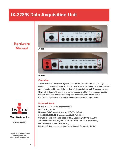
Overview<br />
The <strong>IX</strong>-<strong>228</strong> <strong>Data</strong> <strong>Acquisition</strong> System has 10 input channels and a low voltage<br />
stimulator. The <strong>IX</strong>-<strong>228</strong>S adds an isolated high voltage stimulator. Channels 1 and 2<br />
can be configured for isolated recording of biopotentials or as DC-coupled inputs.<br />
Channels 3 though 10 each include a transducer amplifier. This recorder exhibits<br />
the high resolution and low noise required for small animal cardiovascular<br />
research, oocyte clamp, and high-end metabolic research applications.<br />
<strong>iWorx</strong> Systems, Inc.<br />
www.iworx.com<br />
Included Items<br />
<strong>IX</strong>-<strong>228</strong> or <strong>IX</strong>-<strong>228</strong>S data acquisition unit<br />
USB cable (C-USB)<br />
Universal 5VDC power supply (A-UPS-DC-13-2.6A)<br />
5-lead ECG/EMG/EEG recording cable (C-AAMI-504)<br />
Stimulator cable with snap leads (C-HVS-SL2: only with the <strong>IX</strong>-<strong>228</strong>S)<br />
Stimulator cable with alligator clips (C-HVS-A2: only with the <strong>IX</strong>-<strong>228</strong>S)<br />
Disposable electrodes (A-GC-7165)<br />
LabScribe2 data acquisition software and Quick Start guide (LS-20)<br />
LabScribe2 is a trademark of<br />
<strong>iWorx</strong> Systems, Inc.<br />
©2012 <strong>iWorx</strong> Systems, Inc.<br />
1
<strong>IX</strong>-<strong>228</strong>/S <strong>Data</strong> <strong>Acquisition</strong> <strong>Unit</strong><br />
Front Panel<br />
<strong>IX</strong>-<strong>228</strong> Front Panel<br />
<strong>IX</strong>-<strong>228</strong>S Front Panel<br />
High Voltage Stimulator (on <strong>IX</strong>-<strong>228</strong>S): Suitable for applications ranging from<br />
human striated muscle studies to pacing a rodent’s heart during pressure-volume<br />
loop recording. Connected via HV safety connectors.<br />
CH1 and CH2: Suitable for DC recording and biopotentials. Two-channel<br />
configuration of the bioamplifier allows simultaneous recording of any combination<br />
of ECG, EMG, or EEG signals. A range of high-pass filters (DC, 0.03, 0.3 Hz) and<br />
low-pass filters (10, 20, 30, 40, 50, 60, 70, 80, 90, 100, 150, 200, 300, 400, 500,<br />
600, 700, 800, 900, 1000, 2000, 3000, 4000, 5000, 6000, 7000, 8000, 9000,<br />
10000, 20000 Hz) can be chosen in LabScribe2. Connected via the C-AAMI cable.<br />
Channels 3 through 10: Each channel is equipped with a transducer amplifier to<br />
allow connection of virtually any physiologic transducer via a DIN8 connector.<br />
Low Voltage Stimulator: Parameters for the stimulator, such as pulse width,<br />
frequency and amplitude, may be changed “on the fly” using handy controls<br />
located in the LabScribe2 software toolbar. Standard protocols include Pulse,<br />
Train, Step, Triangle, and Ramp. BNC connectors.<br />
Rear Panel<br />
<strong>IX</strong>-<strong>228</strong>/S Rear Panel<br />
<strong>iWorx</strong> Systems, Inc.<br />
www.iworx.com<br />
2<br />
Power switch<br />
DC Power connector: Accepts 5VDC, 2.6A DC converter.<br />
Synch-Out, Synch-In: Synch-In for triggering the recording from an external<br />
signal, Synch-Out to trigger another device. BNC connectors.
<strong>IX</strong>-<strong>228</strong>/S <strong>Data</strong> <strong>Acquisition</strong> <strong>Unit</strong><br />
Ground: Accepts a banana plug.<br />
USB connector<br />
Digital Input/Output 1 and 2: Eight digital outputs are available to control TTL<br />
devices like pumps and valves, and digital inputs monitor external TTL devices.<br />
Programming is point and click easy; no scripting required.<br />
<strong>iWorx</strong> Systems, Inc.<br />
www.iworx.com<br />
3<br />
SPECIFICATIONS<br />
BIOPOTENTIAL INPUTS (Channels 1 and 2)<br />
Number of inputs 2<br />
Input range<br />
±10VDC<br />
Resolution<br />
16 bit<br />
Connector<br />
C-AAMI cable<br />
TRANSDUCER INPUTS (Channels 3-10)<br />
Number of inputs 8<br />
Input range<br />
±10VDC<br />
Resolution<br />
16 bit<br />
Isolation<br />
No<br />
Excitation<br />
±5VDC, 100mAmp<br />
Connectors<br />
DIN8<br />
Gain<br />
Programmable with input resistor<br />
HIGH VOLTAGE STIMULATOR OUTPUT (on <strong>IX</strong>-<strong>228</strong>S)<br />
Connectors<br />
HV Safety<br />
Output range<br />
0-20mV<br />
Compliance<br />
150VDC<br />
Max ON time<br />
10ms<br />
LOW VOLTAGE STIMULATOR OUTPUT<br />
Resolution<br />
16 bit<br />
Connectors<br />
BNC<br />
Output range<br />
±10VDC<br />
Modes<br />
Pulse, Train, Constant, Step, Ramp, Triangle<br />
A/D CONVERTER<br />
Sampling speed<br />
200k Hz aggregate<br />
Interface<br />
USB 1.1, 2.0, full speed<br />
GENERAL<br />
Power<br />
5VDC, 2.6 amp<br />
Enclosure and Dimensions Plastic; 29.5 cm W, 28 cm D, 6.5 cm H<br />
Warranty<br />
3 years<br />
Software<br />
LabScribe2 Recording and Analysis Software
<strong>IX</strong>-<strong>228</strong>/S <strong>Data</strong> <strong>Acquisition</strong> <strong>Unit</strong><br />
How to Use the <strong>IX</strong>-<strong>228</strong>/S<br />
The <strong>IX</strong>-<strong>228</strong>/S is controlled by LabScribe2 recording and analysis software.<br />
LabScribe2 has an intuitive interface for setting up acquisition screens, calibrating<br />
signals and analyzing data on up to 128 channels simultaneously at sampling rates<br />
as high as 100K samples/second.<br />
For teaching, LabScribe2 includes dozens of laboratory exercises, categorized by<br />
subject areas. Each experiment contains a preconfigured Settings file and a<br />
detailed pdf file with complete instructions for student data recording and analysis.<br />
For research, LabScribe2 uses a comprehensive set of preconfigured analysis<br />
routines, making analysis and interpretation quick and easy. Specific analysis<br />
modules are able to analyze pressure signals, blood flow data, ECG recordings,<br />
ventricular PV loops, and sonomicrometry dimension data.<br />
<strong>iWorx</strong> Systems, Inc.<br />
www.iworx.com<br />
To set up and start to use the <strong>IX</strong>-<strong>228</strong>/S:<br />
1) Download LabScribe2 from www.iworx.com or load the LabScribe2 software<br />
from the provided CD onto the computer. Be sure to install the software before<br />
connecting the hardware for the first time.<br />
2) Plug in and switch on the <strong>IX</strong>-<strong>228</strong>/S.<br />
3) Double-click on the LabScribe2 shortcut to open the software. You should see<br />
a message indicating that the <strong>IX</strong>-<strong>228</strong>/S has been recognized by the software.<br />
4) If you are using the <strong>IX</strong>-<strong>228</strong>/S for teaching, load the appropriate Settings group<br />
and select an experiment. The experiment should open with LabScribe2<br />
preconfigured with appropriate settings. Follow the instructions on the<br />
accompanying pdf to perform the lab exercise. There is no need to configure<br />
the settings manually.<br />
5) If you are using the <strong>IX</strong>-<strong>228</strong>/S for research, you can use the preconfigured<br />
Research settings. It is also possible to create your own Teaching or Research<br />
Settings files. Plug your transducers into the appropriate channels. Channels 1<br />
and 2 are designed for transducers or electrodes requiring DC voltage settings<br />
or a biopotential amplifier. They must be connected via the C-AAMI cable,<br />
connected with pins into the Channel 1 and 2 inputs at the end of the cable.<br />
Channels 3-10 include a transducer amplifier and receive the range of <strong>iWorx</strong><br />
transducers with a DIN8 connector.<br />
6) The Channel 1 and 2 inputs can be configured in one of two different software<br />
locations. In the LabScribe2 Preferences (in the Windows Edit menu, and the<br />
Macintosh LabScribe2 menu), clicking on either Channel 1 or Channel 2 will<br />
open an input configuration dialog. In the recording window itself, if you have<br />
turned on Channels 1 and/or 2 in the Preferences, you can access this same<br />
dialog by clicking on the channel bar just to the right of the channel name.<br />
4
<strong>IX</strong>-<strong>228</strong>/S <strong>Data</strong> <strong>Acquisition</strong> <strong>Unit</strong><br />
Accessing the input configuration dialog from Preferences.<br />
Accessing the input configuration dialog from the Channel Bar.<br />
7) Choose one of the preconfigured modes or click on Input Manager to open a<br />
dialog that allows you to choose the appropriate filters and input range for<br />
your experiment. If you wish to create your own mode, click on New and<br />
name the new mode in the text box. Click OK.<br />
<strong>iWorx</strong> Systems, Inc.<br />
The Input Manager dialog.<br />
www.iworx.com<br />
5
<strong>IX</strong>-<strong>228</strong>/S <strong>Data</strong> <strong>Acquisition</strong> <strong>Unit</strong><br />
Naming the new mode.<br />
8) Return to the Input Manager dialog and choose your mode from the Current<br />
Mode list. Choose the appropriate high-pass filter, low-pass filter, and input<br />
range from each of those dialogs. Click OK.<br />
Filter and input range selection in the Input Manager dialog.<br />
9) Connect any other transducers to the Channels 3 though 10 DIN8 connectors<br />
and turn those channels on.<br />
10) If you are using the Low Voltage Stimulator or the isolated High Voltage<br />
Stimulator (on the <strong>IX</strong>-<strong>228</strong>S), connect your stimulating electrodes to the<br />
appropriate stimulator and use LabScribe2 to control the stimulator as<br />
instructed in the LabScribe2 manual.<br />
<strong>iWorx</strong> Systems, Inc.<br />
www.iworx.com<br />
6<br />
<strong>iWorx</strong> Systems, Inc. 62 Littleworth Road, Dover, New Hampshire 03820<br />
(T) 800-234-1757 / 603-742-2492 (F) 603-742-2455