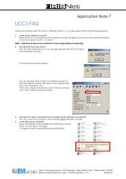
UCC 1 USB-CAN CONVERTER - Electro-Voice
UCC 1 USB-CAN CONVERTER - Electro-Voice
UCC 1 USB-CAN CONVERTER - Electro-Voice

You also want an ePaper? Increase the reach of your titles
YUMPU automatically turns print PDFs into web optimized ePapers that Google loves.
Owner’s Manual<br />
<strong>UCC</strong> 1<br />
<strong>USB</strong>-<strong>CAN</strong> <strong>CONVERTER</strong>
Contents<br />
1. Description....................................................................................................................... 17<br />
2. Controls and Connections................................................................................................ 18<br />
3. Installation ....................................................................................................................... 19<br />
3.1 Unpacking.................................................................................................................... 19<br />
3.2 Rack-Mounting............................................................................................................ 19<br />
4. Initial Operation............................................................................................................... 20<br />
4.1 PC Connection and <strong>CAN</strong> Driver Installation .............................................................. 20<br />
4.2 Installing IRIS.............................................................................................................. 20<br />
4.3 <strong>CAN</strong>-Bus Connection.................................................................................................. 20<br />
4.4 ISOLATED / GROUNDED Switch ............................................................................ 22<br />
5. Monitor Bus..................................................................................................................... 23<br />
6. Technical Information ..................................................................................................... 23<br />
6.1 The <strong>UCC</strong>1 <strong>USB</strong>-<strong>CAN</strong> Converter ................................................................................ 23<br />
6.2 The <strong>CAN</strong>-Bus Standard............................................................................................... 24<br />
6.3 Maximum Cable Length on the <strong>CAN</strong>-Bus .................................................................. 25<br />
7. Specifications................................................................................................................... 27<br />
1. Description<br />
The <strong>UCC</strong>1 <strong>USB</strong>-<strong>CAN</strong> <strong>CONVERTER</strong> is a bi-directional <strong>USB</strong>-to-<strong>CAN</strong> interface converter and is<br />
therefore the perfect solution for interconnecting <strong>Electro</strong>-<strong>Voice</strong> appliances with serial <strong>CAN</strong>-busses and<br />
PC or Notebook computers.<br />
The <strong>UCC</strong>1 is a standalone unit with interface drivers for <strong>CAN</strong> and <strong>USB</strong>, audio monitoring output,<br />
<strong>USB</strong> and <strong>CAN</strong> controllers as well as microphone controllers for converting commands and data<br />
between PC and <strong>CAN</strong>-bus-units. The isolated <strong>CAN</strong>-bus interface reduces ground-loop interference<br />
noise to an absolute minimum. The <strong>UCC</strong>1 receives its operational power via <strong>USB</strong> from the connected<br />
PC, so that no external power supply unit is needed.<br />
This owner’s manual illustrates installation and initial operation of the <strong>UCC</strong>1 when used together with<br />
<strong>Electro</strong>-<strong>Voice</strong> P-Series Remote Amplifiers. Please, carefully read and mind all instructions and<br />
precautions. Keep this owner’s manual at a save place for further reference.<br />
Characteristics<br />
• Data rate up to 500 kbit/s<br />
• Galvanic separation of the <strong>CAN</strong>-bus, switchable<br />
• 100 network devices possible<br />
• Monitor-bus in network cabling; output signal via XLR-type connector<br />
• Power supply via <strong>USB</strong> from the connected PC; separate power supply unit is not<br />
needed<br />
17
2. Controls and Connections<br />
Fig. 1: <strong>UCC</strong>1 front panel<br />
1. <strong>USB</strong> connector<br />
This connector is for the connection to the <strong>USB</strong>-port on your PC. The interface complies with the<br />
<strong>USB</strong> 1.1 specifications and offers data transfer as well as operation voltage supply for the <strong>UCC</strong>1.<br />
2. STATUS indicator<br />
The STATUS LED indicates the actual operational state of the <strong>UCC</strong>1. The indicator lights when<br />
the <strong>UCC</strong>1 has been connected to the PC, the dedicated driver software has been installed, and the<br />
PC has recognized the unit. The LED blinks during data accesses.<br />
3. <strong>CAN</strong> ISOLATED / GROUNDED switch<br />
Setting this switch to ISOLATED galvanically isolates the <strong>CAN</strong>-port of the <strong>UCC</strong>1 from the rest of<br />
the circuitry, effectively eliminating ground-loop interference noise. Setting the switch to<br />
GROUNDED galvanically connects the <strong>CAN</strong>-bus to the <strong>USB</strong>-port ground and thus to the PC.<br />
Fig 2: <strong>UCC</strong>1 rear view<br />
4. <strong>CAN</strong> BUS IN / OUT connectors<br />
These two sockets are for connecting EV-appliances that are furnished with serial <strong>CAN</strong>-bus. Both<br />
connectors are connected in parallel for convenient carrying through <strong>CAN</strong>-bus data.<br />
5. MONITOR connector<br />
The MONITOR connector provides audio signal output for the monitor bus of EV P-Series<br />
Remote Amps. The monitor bus allows listening to the audio signal of any amplifier within the<br />
system, without the need for additional wiring.<br />
18
3. Installation<br />
3.1 Unpacking<br />
The <strong>UCC</strong>1 package includes the following parts:<br />
1 <strong>UCC</strong>1 <strong>USB</strong>-<strong>CAN</strong> <strong>CONVERTER</strong><br />
1 Front panel 19“, 1HU<br />
2 <strong>CAN</strong>-TERM 120 Ω <strong>CAN</strong>-bus terminator-plug<br />
4 Rubber feet<br />
1 <strong>USB</strong> cable<br />
1 Owner’s manual<br />
Upon receiving your <strong>UCC</strong>1, please inspect the contents of the package for loss or damage. If any of<br />
the here listed parts are missing or damaged, please immediately contact your distributor or a TELEX /<br />
EVI Audio service center.<br />
3.2 Rack-Mounting<br />
The compact <strong>UCC</strong>1 adapter is mainly aimed for connection to a laptop or notebook computer.<br />
However, the supplied 19“ front panel allows trouble-free integration in a rack shelf system. For<br />
mounting the 19“ front panel, please proceed as follows:<br />
1. Loosen the two center screws on the <strong>UCC</strong>1’s panel (1).<br />
2. Loosen the four corner screws on the <strong>UCC</strong>1’s panel (2).<br />
3. Remove the original <strong>UCC</strong>1 panel (3).<br />
Fig. 3: Exchanging <strong>UCC</strong>1 front panels<br />
4. Fix the 19“ front panel on the <strong>UCC</strong>1. In doing so, make sure not to damage, bend or stress the<br />
STATUS indicator and the ISOLATED / GROUNDED switch. (4).<br />
5. Reinsert and tighten the two center screws of the <strong>UCC</strong>1 19“ panel (5).<br />
6. Reinsert and tighten the four corner screws of the <strong>UCC</strong>1 enclosure (6).<br />
Now you are able to install the <strong>UCC</strong>1 in a rack shelf system securing it with the four rack-screws on<br />
the sides.<br />
19
4. Initial Operation<br />
Follow these four steps when operating the <strong>UCC</strong>1 for the first time: Connect the <strong>UCC</strong>1 to the PC and<br />
install the <strong>CAN</strong> drivers, install the IRIS-software, connect the desired appliances to the <strong>CAN</strong>-bus, and<br />
set the ISOLATED / GROUNDED switch accordingly.<br />
4.1 PC Connection and <strong>CAN</strong> Driver Installation<br />
Use the supplied <strong>USB</strong> cable for connecting the <strong>UCC</strong>1 to your PC’s or Notebook’s <strong>USB</strong>-socket. The<br />
computer system normally recognizes the <strong>UCC</strong>1 at once and the operating system asks for the<br />
corresponding driver software. This files are stored in the root directory of the IRIS CD.<br />
Insert the IRIS CD in your CD-drive and select the corresponding drive in the installation dialog. The<br />
operating system will find all necessary driver files there. For correct installation follow the<br />
instructions on your computer screen. For further information please check the IRIS Readme-File,<br />
also.<br />
The <strong>UCC</strong>1 is ready for operation as soon as the STATUS LED lights.<br />
4.2 Installing IRIS<br />
Next, you have to install the IRIS – Intelligent Remote & Integrated Supervision – software package<br />
on your PC or Notebook computer. Detailed explanation is provided in the accompanying IRIS<br />
Readme-File. Just follow the instructions in the installation dialog.<br />
The STATUS LED blinks whenever the IRIS program is started and accesses the <strong>UCC</strong>1, indicating<br />
that <strong>USB</strong>-port data communication has been activated.<br />
4.3 <strong>CAN</strong>-Bus Connection<br />
The <strong>CAN</strong>-bus is a serial interface for transferring commands and data. Since the <strong>CAN</strong>-bus is based on<br />
serial bus architecture, all participating appliances have to be connected in series, i.e. cables have to<br />
run from each participant on the bus system to the next. Whether a connected appliance is an amplifier<br />
or the <strong>UCC</strong>1 <strong>USB</strong>-<strong>CAN</strong> Converter is generally of no further importance, which allows the integration<br />
of the <strong>UCC</strong>1 – and therefore the PC – at any point on the <strong>CAN</strong>-bus. Including several <strong>UCC</strong>1s and PCs<br />
on a single <strong>CAN</strong>-bus is possible as well.<br />
Each participant on the bus system has two RJ-45 connectors for the Remote <strong>CAN</strong>-bus. These sockets<br />
are connected in parallel to serve as input and output for carrying through the data information of the<br />
remote-network. The <strong>CAN</strong>-port follows balanced design, which makes the use of Twisted-Pair cables<br />
absolutely mandatory.<br />
Both ends of the <strong>CAN</strong>-bus have to be terminated with 120 Ω. Two <strong>CAN</strong>-TERM 120 Ω termination<br />
plugs are supplied with the <strong>UCC</strong>1. Connect one of these each to the RJ-45 connector that is not in use<br />
of the first and the last appliance on <strong>CAN</strong>-bus.<br />
The following diagrams are examples of the system cabling for different order of size configurations:<br />
20
Fig 4: System set-up with 5 amps and a single <strong>UCC</strong>1 / PC being the first unit on the bus<br />
Terminators at the <strong>UCC</strong>1 (first unit) and at the amp No.5 (last unit on the bus)<br />
Fig 5: System set-up with 2 racks and a single <strong>UCC</strong>1 / PC in the middle<br />
Terminators at amp No. 6 (first unit) and amp No. 12 (last unit on the bus)<br />
21
Fig 6: System with several racks and several <strong>UCC</strong>1 / PCs<br />
<strong>UCC</strong>1 anywhere on the <strong>CAN</strong>-bus<br />
Terminators at amp No. 10 (first unit) and amp No. 16 (last unit on the bus)<br />
4.4 ISOLATED / GROUNDED Switch<br />
Principally, the <strong>CAN</strong>-bus is galvanically isolated from any other participant on the bus, i.e. from all P-<br />
Series Remote amps and from the <strong>UCC</strong>1 <strong>USB</strong>-<strong>CAN</strong> Converter as well, a circumstance which as a<br />
matter of fact results in effective elimination of ground-loop interference noise.<br />
22
The ISOLATED / GROUNDED switch located on the <strong>UCC</strong>1’s front panel allows bridging this<br />
galvanic isolation putting the <strong>CAN</strong>-bus of the <strong>UCC</strong>1 on circuitry ground potential.<br />
The <strong>CAN</strong>-bus should normally be referenced to the ground potential at one single point in the<br />
network. Set the switch to its GROUNDED-position when only one <strong>UCC</strong>1 is used in a single <strong>CAN</strong>bus<br />
network. When employing several <strong>UCC</strong>1s in a <strong>CAN</strong>-bus network, setting the ISOLATED /<br />
GROUNDED switch of one <strong>UCC</strong>1 to GROUNDED while leaving the switches of all other <strong>UCC</strong>1s in<br />
the ISOLATED-position is recommended.<br />
5. Monitor Bus<br />
Next to the <strong>CAN</strong>-bus signal, network cabling also holds the balanced audio-monitor signal for<br />
monitoring the power amp inputs and outputs. This monitor-bus allows software-controlled<br />
monitoring of the input and output signals of all power amps that are included in the remote network,<br />
without the need for additional wiring. The monitor signal is present at the <strong>UCC</strong>1’s XLR-type<br />
MONITOR Output connector for further distribution to (e.g.) a mixing console to be monitored via<br />
headphones or an active monitor speaker connected.<br />
6. Technical Information<br />
6.1 The <strong>UCC</strong>1 <strong>USB</strong>-<strong>CAN</strong> Converter<br />
The <strong>UCC</strong>1 is an <strong>USB</strong>-to-<strong>CAN</strong> adapter, which offers the possibility to easily include any PC or<br />
Notebook computer that is equipped with an <strong>USB</strong>-port in an existing <strong>CAN</strong>-network. The <strong>USB</strong> driver,<br />
which is part of the IRIS-software is the only thing needed for triggering. The <strong>UCC</strong>1 gets its power<br />
supply from the PC’s <strong>USB</strong>-port, so that no external power supply unit is necessary.<br />
The following block diagram shows the <strong>UCC</strong>1’s internal structure with <strong>USB</strong>-port and controller on the<br />
one side and the <strong>CAN</strong>-bus interface with <strong>CAN</strong>-transceiver component and galvanic separation on the<br />
other side. The controller is responsible for the data format conversion between <strong>USB</strong>-port and <strong>CAN</strong>bus,<br />
allowing data rates of up to 500 kbit/s.<br />
Next to the <strong>CAN</strong>-bus, the network cabling also holds the monitor bus, which serves for monitoring the<br />
input or output audio signals of all amplifiers that are included in the network. This audio signal is<br />
present at the <strong>UCC</strong>1’s XLR-type MONITOR Output connector to provide trouble-free connection to a<br />
mixer input or an additional amplifier.<br />
<strong>USB</strong><br />
DATA<br />
ISOLATED<br />
GROUNDED<br />
<strong>CAN</strong><br />
GND<br />
<strong>USB</strong> & <strong>CAN</strong><br />
CONTROLLER<br />
<strong>USB</strong><br />
GND<br />
ISOLATION <strong>CAN</strong><br />
TRANSCEIVER<br />
23<br />
<strong>CAN</strong><br />
GND<br />
Fig. 7: <strong>UCC</strong>1 Block Diagram<br />
2 1<br />
3<br />
IN<br />
<strong>CAN</strong> BUS<br />
OUT<br />
MONITOR<br />
<strong>CAN</strong> Bus<br />
Monitor Bus<br />
The <strong>CAN</strong>-bus port of the <strong>UCC</strong>1 (<strong>CAN</strong> BUS IN / OUT) is carried out via two Neutrik EtherCon<br />
connectors to ensure most secure and reliably safe RJ-45 connections even under most wearing<br />
conditions. The EtherCon connector series has been specially designed for use in ProAudio and On-<br />
Stage applications. Matching Neutrik plug-type – NE8MC – connectors are also available.
The pin-assignment of <strong>CAN</strong>-bus connectors is shown in figure 8.<br />
6.2 The <strong>CAN</strong>-Bus Standard<br />
Fig. 8: <strong>CAN</strong> BUS IN / OUT connector pin-assignment<br />
Developed in the 1980’s, the <strong>CAN</strong>-bus norm had been established in the 1990’s by the International<br />
Standardization Organization (ISO) as a worldwide standard. Since then, <strong>CAN</strong> has become very<br />
popular especially in automotive and industrial applications. <strong>CAN</strong> is cared for and further developed<br />
by the CiA (<strong>CAN</strong> in Automation User Organization), an association of 300 well-known companies<br />
engaged in different areas.<br />
The <strong>CAN</strong>-Bus employs the so-called „Bus-Topology“ as network topology; i.e. all participants on the<br />
bus are connected via one single two-wire line (Twisted-Pair-cable, with or without shielding), which,<br />
at its ends has to be terminated using 120 Ω bus termination plugs. Each appliance on the bus can<br />
communicate with any other unit without restriction. Up to 100 network devices can be connected on a<br />
single <strong>CAN</strong>-Bus.<br />
Because the <strong>CAN</strong>-interfaces of all EVI Audio appliances is galvanically isolated from the rest of the<br />
circuitry, network cabling also carries a common ground (<strong>CAN</strong>_GND), which guarantees that all<br />
<strong>CAN</strong>-interfaces in the network are connected to the same ground potential. The ISOLATED /<br />
GROUNDED switch in the <strong>UCC</strong>1 offers the possibility for switching the <strong>CAN</strong>-Ground (<strong>CAN</strong>_GND)<br />
to circuitry ground potential. Normally, one <strong>UCC</strong>1’s switch should be set to its GROUNDED-position<br />
while all other <strong>UCC</strong>1s in the network should be set to ISOLATED.<br />
<strong>CAN</strong><br />
DEVICE<br />
1<br />
<strong>CAN</strong><br />
DEVICE<br />
2<br />
<strong>CAN</strong>_H<br />
24<br />
<strong>CAN</strong><br />
DEVICE<br />
n<br />
BUS TERMINATION<br />
120 Ω<br />
<strong>CAN</strong> BUS UP TO 1000 m<br />
BUS TERMINATION<br />
120Ω<br />
<strong>CAN</strong>_L<br />
<strong>CAN</strong>_GND<br />
Fig. 9: Bus-topology of the <strong>CAN</strong>-bus<br />
The <strong>CAN</strong>-bus allows using different data rates. The actual data rate is indirect proportional to the bus<br />
length. “Smaller” networks with short bus lengths permit higher baud rates of up to 500 kbaud. The<br />
baud rate needs to be reduced (minimum 10 kbaud) in networks with extensive bus length. The<br />
following table shows the relation between baud rate and bus length:
Baud Rate Bus Length<br />
500 kbit/s 100 m<br />
250 kbit/s 250 m<br />
125 kbit/s 500 m<br />
62,5 kbit/s 1000 m<br />
20 kbit/s 2500 m<br />
10 kbit/s 5000 m<br />
The use of repeaters is generally recommended when a network’s bus length exceeds 1000 m.<br />
6.3 Maximum Cable Length on the <strong>CAN</strong>-Bus<br />
According to the ISO 11898-2 standard, <strong>CAN</strong>-bus data transfer cabling has to be carried out using<br />
Twisted-Pair cables with or without shielding providing a characteristic impedance of 120 Ω. Both<br />
ends of a <strong>CAN</strong>-network have to be terminated with 120 Ω termination plugs.<br />
The maximum bus length depends on the actual data transfer rate, which kind of data transfer cable is<br />
used and the total number of participants on the bus. The following table shows the most essential<br />
coherencies for <strong>CAN</strong>-networks consisting of up to 64 participants:<br />
Bus Length<br />
0 ... 40 m < 70 mΩ/m<br />
40 ... 300 m < 60 mΩ/m<br />
300 ... 600 m < 40 mΩ/m<br />
600 ... 1000 m < 26 mΩ/m<br />
Data Transfer Cable<br />
Length-Related Cable Diameter<br />
Resistance<br />
0,25 ... 0,34 mm 2<br />
AWG23, AWG22<br />
0,34 ... 0,6 mm 2<br />
AWG22, AWG20<br />
0, 5 ... 0,6 mm 2<br />
AWG20<br />
0,75 ... 0,8 mm 2<br />
AWG18<br />
25<br />
Termination<br />
Max.<br />
Data Transfer Rate<br />
124 Ω 1000 kbit/s for 40 m<br />
127 Ω 500 kbit/s for 100 m<br />
150 ... 300 Ω * 100 kbit/s for 500 m<br />
150 ... 300 Ω * 62,5 kbit/s for 1000 m<br />
* To reduce the load for the interface driver and therefore also reducing the voltage drop between the<br />
two cable ends, using higher impedance termination than the specified 120 Ω is recommended for<br />
networks with increased cable length and many nodes on the <strong>CAN</strong>-bus.<br />
The following table is for estimating the necessary cable diameter in relation to the length and the<br />
amount of participants on the bus:<br />
Bus Length<br />
32<br />
Number of Units on the <strong>CAN</strong>-bus<br />
64 100<br />
100 m 0,25 mm 2 respectively AWG24 0,34 mm 2 respectively AWG22 0,34 mm 2 respectively AWG22<br />
250 m 0,34 mm 2 respectively AWG22 0,5 mm 2 respectively AWG20 0,5 mm 2 respectively AWG20<br />
500 m 0,75 mm 2 respectively AWG18 0,75 mm 2 respectively AWG18 1,0 mm 2 respectively AWG17
Additionally, the length of any stub lines for participants that are not directly connected to the <strong>CAN</strong>bus<br />
needs to be kept in mind. For data transfer rates of up to 125 kbit/s the length of a single stub cable<br />
should not exceed 2 m. For higher bit rates a length of max. 0.3 m has not to be exceeded. The entire<br />
length of all stub lines should not exceed 30 m.<br />
General note:<br />
Using commercial quality RJ-45 patch cables with a characteristic impedance of 100 Ω (AWG<br />
24 / AWG 26) for rack cabling is generally possible for short distances of up to 10 m.<br />
For the interconnection of rack shelf systems as well as in fixed installations obeying the<br />
guidelines for network cabling, as mentioned above, is mandatory.<br />
26
7. Specifications<br />
<strong>CAN</strong> BUS:<br />
Sockets 2 x RJ-45 parallel (NEUTRIK EtherCon compatible)<br />
Baud Rate 500 / 250 / 125 / 62,5 / 20 / 10 kbit/s<br />
Number of Nodes 100 max.<br />
Data Format <strong>CAN</strong> specification 2.0B (29 bit ID)<br />
Cable Length 1000 m at 62,5 kbit/s<br />
<strong>USB</strong>:<br />
Socket <strong>USB</strong> socket, Type B<br />
Standard <strong>USB</strong> 1.1<br />
Cable Length 3m max.<br />
MONITOR:<br />
Socket XLR male, electronically balanced (Pin 2 = +, Pin 3 = -)<br />
Output Voltage (nominal) 1.55 V / +6 dBu<br />
Max. Output Voltage 8.7 V / +21 dBu<br />
Output Impedance < 100 Ω<br />
Min. Load Impedance 600 Ω<br />
Power Supply + 5 V DC (from <strong>USB</strong> interface)<br />
Power Consumption 200 mA max.<br />
Operation Temperature Range 0 °C … 50 °C<br />
Certified CE<br />
Dimensions 105 x 39.5 x 130.4 mm (W x H x D)<br />
with 19“ panel 483 x 43.6 x 130.4 mm (W x H x D), 19“ / 1 HU<br />
Weight 0.8 kg (with 19“ panel)<br />
Accessories 19“ panel for rack installation<br />
<strong>CAN</strong>-TERM 120 Ω termination plug (2x)<br />
- subject to changes without further notice -<br />
27