ner Controls AGM... - Romstal
ner Controls AGM... - Romstal
ner Controls AGM... - Romstal

Create successful ePaper yourself
Turn your PDF publications into a flip-book with our unique Google optimized e-Paper software.
7 230<br />
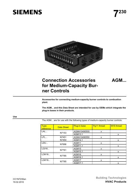
Connection Accessories<br />
for Medium-Capacity Bur<strong>ner</strong><br />
<strong>Controls</strong><br />
<strong>AGM</strong>...<br />
Accessories for connecting medium-capacity bur<strong>ner</strong> controls to combustion<br />
plant.<br />
The <strong>AGM</strong>... and this Data Sheet are intended for use by OEMs which integrate the<br />
plug-in bases in their products.<br />
Use<br />
The <strong>AGM</strong>... are for use with the following types of medium-capacity bur<strong>ner</strong> controls:<br />
Type<br />
reference<br />
LAL...<br />
LFL...<br />
LDU...<br />
LGI16...<br />
LOK16...<br />
LGK16...<br />
Data Sheet<br />
Plug-in base Pg11 thread M16 thread<br />
N7153<br />
<strong>AGM</strong>410490500<br />
x<br />
<strong>AGM</strong>13.1<br />
x<br />
N7451 <strong>AGM</strong>410490550<br />
x<br />
N7454 <strong>AGM</strong>14.1 x<br />
N7696<br />
<strong>AGM</strong>11<br />
x<br />
<strong>AGM</strong>11.1<br />
x<br />
N7761<br />
<strong>AGM</strong>15<br />
x<br />
<strong>AGM</strong>15.1<br />
x<br />
N7785<br />
<strong>AGM</strong>16<br />
x<br />
<strong>AGM</strong>16.1<br />
x<br />
N7785<br />
<strong>AGM</strong>17<br />
x<br />
<strong>AGM</strong>17.1<br />
x<br />
CC1N7230en<br />
19.02.2010<br />
Building Technologies<br />
HVAC Products
Warning notes<br />
To avoid injury to persons, damage to property or the environment, the following<br />
warning notes must be observed!<br />
• All activities (mounting, installation and service work, etc.) must be performed by<br />
qualified staff<br />
• Before making any wiring changes in the connection area, completely isolate the<br />
plant from mains supply (all-polar disconnection). Ensure that the plant cannot be<br />
inadvertently switched on again and that it is indeed dead. If not disconnected, there<br />
is a risk of electric shock hazard<br />
• Protection against electric shock hazard on the <strong>AGM</strong>... and on all connected electrical<br />
components must be ensured through adequate mounting. In terms of design,<br />
stability and protection, the cover must conform to EN 60730<br />
• After each activity (mounting, installation and service work, etc.), check to ensure<br />
that wiring is in an orderly state<br />
Mounting notes<br />
• Ensure that the relevant national safety regulations and standard notes are complied<br />
with<br />
• Connect the earthing lug on the <strong>AGM</strong>... plug-in base to the bur<strong>ner</strong> using a metric<br />
screw and a lockwasher or similar<br />
Installation notes<br />
• Do not mix up live and neutral conductors (dangerous malfunctions, loss of protection<br />
against electric shock hazard, etc.)<br />
• Decisive for the electrical connections of valves and other plant components are<br />
the plant diagram and the mounting and commissioning instructions provided by<br />
the bur<strong>ner</strong> supplier<br />
• To isolate the plant from the mains supply, use an all-polar switch with a contact<br />
gap of at least 3 mm<br />
• To protect the bur<strong>ner</strong> control electrically, install a primary fuse<br />
Standards and certificates<br />
Conformity to EEC directives<br />
- Electromagnetic compatibility EMC (immunity)<br />
- Low-voltage directive<br />
2004/108/EC<br />
2006/95/EC<br />
ISO 9001: 2000<br />
Cert. 00739<br />
ISO 14001: 2004<br />
Cert. 38233<br />
Disposal notes<br />
The plug-in base must not be disposed of together with household waste. Local and<br />
currently valid legislation must be observed.<br />
2/7<br />
Building Technologies<br />
CC1N7230en<br />
HVAC Products 19.02.2010
Mechanical design<br />
- Made of black, impact-proof and heat-resistant plastic<br />
- Plug-in base and connectors of the bur<strong>ner</strong> control are designed such that only the<br />
correct bur<strong>ner</strong> control can be fitted<br />
- 24 connection terminals<br />
- Auxiliary terminals «31» and «32»<br />
- 3 earth conductor terminals, joining in a lug for earthing the bur<strong>ner</strong><br />
- 3 neutral conductor terminals (prewired to terminal 2)<br />
- 14 knockout holes for cable entry via cable entry glands (8 laterally, 6 in the bottom)<br />
- 6 lateral treaded knockout holes for cable entry glands Pg11 or M16<br />
Markings on the<br />
plug-in base<br />
Example: LGK16...:<br />
1 2 3 4 5 6 7 8 9 10 11 12<br />
13 14 15 16 17 18 19 20 21 22 23 24<br />
31<br />
N<br />
LGK<br />
32<br />
9029<br />
9683<br />
Bur<strong>ner</strong> control LGK16...<br />
M16 thread<br />
7230z01e/0404<br />
Pg11 thread: Marked 9029 on the plug-in base (refer to «Dimensions»).<br />
M16 thread: Marked 9683 on the plug-in base (refer to «Dimensions»).<br />
Note<br />
A coded pin in the plug-in base ensures that bur<strong>ner</strong> controls with other functions cannot<br />
be fitted!<br />
3/7<br />
Building Technologies<br />
CC1N7230en<br />
HVAC Products 19.02.2010
Ordering<br />
Plug-in base for use with valve proving device LDU...<br />
- With Pg11 thread ¹) <strong>AGM</strong>11<br />
- With M16 thread ²) <strong>AGM</strong>11.1<br />
Plug-in base for use with bur<strong>ner</strong> controls LAL...<br />
- With Pg11 thread ¹) <strong>AGM</strong>410490500<br />
- With M16 thread ²) <strong>AGM</strong>13.1<br />
Plug-in base for use with bur<strong>ner</strong> controls LFL...<br />
- With Pg11 thread ¹) <strong>AGM</strong>410490550<br />
- With M16 thread ²) <strong>AGM</strong>14.1<br />
Plug-in base for use with bur<strong>ner</strong> controls LGI16... (supplied with wire link«J»)<br />
- With Pg11 thread ¹) <strong>AGM</strong>15<br />
- With M16 thread ²) <strong>AGM</strong>15.1<br />
Plug-in base for use with bur<strong>ner</strong> controls LOK16...<br />
- With Pg11 thread ¹) <strong>AGM</strong>16<br />
- With M16 thread ²) <strong>AGM</strong>16.1<br />
Plug-in base for use with bur<strong>ner</strong> controls LGK16...<br />
- With Pg11 thread ¹) <strong>AGM</strong>17<br />
- With M16 thread ²) <strong>AGM</strong>17.1<br />
¹) Marked 9029 on the plug-in base (refer to «Dimensions»)<br />
²) Marked 9683 on the plug-in base (refer to «Dimensions»)<br />
4/7<br />
Building Technologies<br />
CC1N7230en<br />
HVAC Products 19.02.2010
Technical data<br />
Ge<strong>ner</strong>al data<br />
Weight<br />
Degree of protection<br />
Tightening torque<br />
- Cable with ferrules<br />
Loosening torque<br />
Max. cross-sectional area<br />
- Terminals<br />
- Auxiliary terminals N, PE, 31 and 32<br />
Ferrules<br />
Approx. 165 g<br />
IP00<br />
To DIN EN 60335-1<br />
50 Ncm<br />
40 Ncm<br />
Min. 0.5 mm²<br />
Max. 1.5 mm²<br />
Solid wire or stranded wire with ferrule<br />
Min. 0.5 mm²<br />
Max. 1.5 mm²<br />
Solid wire or stranded wire with ferrule<br />
(when connecting 2 solid wires or stranded<br />
wires per terminal, same cross-sectional<br />
areas must be used)<br />
Matching the cross-sectional area of the<br />
stranded wire<br />
Environmental<br />
conditions<br />
Storage DIN EN 60721-3-1<br />
Climatic conditions<br />
Class 1K3<br />
Mechanical conditions<br />
Class 1M2<br />
Temperature range<br />
-40...+60°C<br />
Humidity<br />
Dimensions<br />
Plug-in base <strong>AGM</strong>…<br />
with Pg11 threads<br />
Dimensions in mm<br />
Pg11<br />
25 25<br />
6<br />
7<br />
5,2x6,7<br />
40 18,5 13,5 5,7<br />
15,5<br />
30<br />
7,5<br />
5<br />
15 15 15<br />
51,5<br />
51,5<br />
40<br />
26,8<br />
1 2 3 4 5 6 7 8 9 10 11 12<br />
13 14 15 16 17 18 19 20 21 22 23 24<br />
31<br />
7,5 18,9<br />
5,2<br />
5,7 12,8<br />
N<br />
XXX<br />
32<br />
9029<br />
9683<br />
40<br />
1,5<br />
4,4<br />
7230m01/0204<br />
1<br />
12,8 5,7<br />
25 15<br />
5,2x6,7<br />
51,5<br />
51,5<br />
6/7<br />
Building Technologies<br />
CC1N7230en<br />
HVAC Products 19.02.2010
Dimensions (cont‘d)<br />
Plug-in base <strong>AGM</strong>…<br />
with M16 threads<br />
Dimensions in mm<br />
M16x1,5<br />
25 25<br />
6<br />
7<br />
5,2x6,7<br />
40 18,5 13,5 5,7<br />
51,5<br />
15,5<br />
30<br />
7,5<br />
5<br />
15 15 15<br />
51,5<br />
40<br />
26,8<br />
1 2 3 4 5 6 7 8 9 10 11 12<br />
13 14 15 16 17 18 19 20 21 22 23 24<br />
31<br />
7,5 18,9<br />
5,2<br />
5,7 12,8<br />
N<br />
XXX<br />
32<br />
9029<br />
9683<br />
40<br />
1,5<br />
4,4<br />
7230m02/0204<br />
1<br />
12,8 5,7<br />
25 15<br />
5,2x6,7<br />
51,5<br />
51,5<br />
©2010 Siemens Building Technologies HVAC Products GmbH<br />
Subject to change!<br />
7/7<br />
Building Technologies<br />
CC1N7230en<br />
HVAC Products 19.02.2010